EP4276053A2 - Post-mix flavoured carbonated beverage dispenser - Google Patents
Post-mix flavoured carbonated beverage dispenser Download PDFInfo
- Publication number
- EP4276053A2 EP4276053A2 EP23172974.0A EP23172974A EP4276053A2 EP 4276053 A2 EP4276053 A2 EP 4276053A2 EP 23172974 A EP23172974 A EP 23172974A EP 4276053 A2 EP4276053 A2 EP 4276053A2
- Authority
- EP
- European Patent Office
- Prior art keywords
- flavorant
- fluid
- container
- beverage
- carriage assembly
- Prior art date
- Legal status (The legal status is an assumption and is not a legal conclusion. Google has not performed a legal analysis and makes no representation as to the accuracy of the status listed.)
- Pending
Links
Images
















Classifications
-
- A—HUMAN NECESSITIES
- A23—FOODS OR FOODSTUFFS; TREATMENT THEREOF, NOT COVERED BY OTHER CLASSES
- A23L—FOODS, FOODSTUFFS OR NON-ALCOHOLIC BEVERAGES, NOT OTHERWISE PROVIDED FOR; PREPARATION OR TREATMENT THEREOF
- A23L2/00—Non-alcoholic beverages; Dry compositions or concentrates therefor; Preparation or treatment thereof
- A23L2/52—Adding ingredients
- A23L2/56—Flavouring or bittering agents
-
- A—HUMAN NECESSITIES
- A47—FURNITURE; DOMESTIC ARTICLES OR APPLIANCES; COFFEE MILLS; SPICE MILLS; SUCTION CLEANERS IN GENERAL
- A47J—KITCHEN EQUIPMENT; COFFEE MILLS; SPICE MILLS; APPARATUS FOR MAKING BEVERAGES
- A47J31/00—Apparatus for making beverages
- A47J31/44—Parts or details or accessories of beverage-making apparatus
- A47J31/46—Dispensing spouts, pumps, drain valves or like liquid transporting devices
- A47J31/461—Valves, e.g. drain valves
-
- A—HUMAN NECESSITIES
- A47—FURNITURE; DOMESTIC ARTICLES OR APPLIANCES; COFFEE MILLS; SPICE MILLS; SUCTION CLEANERS IN GENERAL
- A47J—KITCHEN EQUIPMENT; COFFEE MILLS; SPICE MILLS; APPARATUS FOR MAKING BEVERAGES
- A47J31/00—Apparatus for making beverages
- A47J31/40—Beverage-making apparatus with dispensing means for adding a measured quantity of ingredients, e.g. coffee, water, sugar, cocoa, milk, tea
-
- A—HUMAN NECESSITIES
- A23—FOODS OR FOODSTUFFS; TREATMENT THEREOF, NOT COVERED BY OTHER CLASSES
- A23L—FOODS, FOODSTUFFS OR NON-ALCOHOLIC BEVERAGES, NOT OTHERWISE PROVIDED FOR; PREPARATION OR TREATMENT THEREOF
- A23L2/00—Non-alcoholic beverages; Dry compositions or concentrates therefor; Preparation or treatment thereof
- A23L2/52—Adding ingredients
- A23L2/54—Mixing with gases
-
- A—HUMAN NECESSITIES
- A47—FURNITURE; DOMESTIC ARTICLES OR APPLIANCES; COFFEE MILLS; SPICE MILLS; SUCTION CLEANERS IN GENERAL
- A47J—KITCHEN EQUIPMENT; COFFEE MILLS; SPICE MILLS; APPARATUS FOR MAKING BEVERAGES
- A47J31/00—Apparatus for making beverages
- A47J31/40—Beverage-making apparatus with dispensing means for adding a measured quantity of ingredients, e.g. coffee, water, sugar, cocoa, milk, tea
- A47J31/402—Liquid dosing devices
-
- A—HUMAN NECESSITIES
- A47—FURNITURE; DOMESTIC ARTICLES OR APPLIANCES; COFFEE MILLS; SPICE MILLS; SUCTION CLEANERS IN GENERAL
- A47J—KITCHEN EQUIPMENT; COFFEE MILLS; SPICE MILLS; APPARATUS FOR MAKING BEVERAGES
- A47J31/00—Apparatus for making beverages
- A47J31/40—Beverage-making apparatus with dispensing means for adding a measured quantity of ingredients, e.g. coffee, water, sugar, cocoa, milk, tea
- A47J31/407—Beverage-making apparatus with dispensing means for adding a measured quantity of ingredients, e.g. coffee, water, sugar, cocoa, milk, tea with ingredient-containing cartridges; Cartridge-perforating means
-
- A—HUMAN NECESSITIES
- A47—FURNITURE; DOMESTIC ARTICLES OR APPLIANCES; COFFEE MILLS; SPICE MILLS; SUCTION CLEANERS IN GENERAL
- A47J—KITCHEN EQUIPMENT; COFFEE MILLS; SPICE MILLS; APPARATUS FOR MAKING BEVERAGES
- A47J31/00—Apparatus for making beverages
- A47J31/40—Beverage-making apparatus with dispensing means for adding a measured quantity of ingredients, e.g. coffee, water, sugar, cocoa, milk, tea
- A47J31/41—Beverage-making apparatus with dispensing means for adding a measured quantity of ingredients, e.g. coffee, water, sugar, cocoa, milk, tea of liquid ingredients
-
- A—HUMAN NECESSITIES
- A47—FURNITURE; DOMESTIC ARTICLES OR APPLIANCES; COFFEE MILLS; SPICE MILLS; SUCTION CLEANERS IN GENERAL
- A47J—KITCHEN EQUIPMENT; COFFEE MILLS; SPICE MILLS; APPARATUS FOR MAKING BEVERAGES
- A47J31/00—Apparatus for making beverages
- A47J31/44—Parts or details or accessories of beverage-making apparatus
-
- A—HUMAN NECESSITIES
- A47—FURNITURE; DOMESTIC ARTICLES OR APPLIANCES; COFFEE MILLS; SPICE MILLS; SUCTION CLEANERS IN GENERAL
- A47J—KITCHEN EQUIPMENT; COFFEE MILLS; SPICE MILLS; APPARATUS FOR MAKING BEVERAGES
- A47J31/00—Apparatus for making beverages
- A47J31/44—Parts or details or accessories of beverage-making apparatus
- A47J31/46—Dispensing spouts, pumps, drain valves or like liquid transporting devices
- A47J31/468—Pumping means
-
- A—HUMAN NECESSITIES
- A47—FURNITURE; DOMESTIC ARTICLES OR APPLIANCES; COFFEE MILLS; SPICE MILLS; SUCTION CLEANERS IN GENERAL
- A47J—KITCHEN EQUIPMENT; COFFEE MILLS; SPICE MILLS; APPARATUS FOR MAKING BEVERAGES
- A47J31/00—Apparatus for making beverages
- A47J31/44—Parts or details or accessories of beverage-making apparatus
- A47J31/52—Alarm-clock-controlled mechanisms for coffee- or tea-making apparatus ; Timers for coffee- or tea-making apparatus; Electronic control devices for coffee- or tea-making apparatus
- A47J31/525—Alarm-clock-controlled mechanisms for coffee- or tea-making apparatus ; Timers for coffee- or tea-making apparatus; Electronic control devices for coffee- or tea-making apparatus the electronic control being based on monitoring of specific process parameters
-
- B—PERFORMING OPERATIONS; TRANSPORTING
- B01—PHYSICAL OR CHEMICAL PROCESSES OR APPARATUS IN GENERAL
- B01F—MIXING, e.g. DISSOLVING, EMULSIFYING OR DISPERSING
- B01F23/00—Mixing according to the phases to be mixed, e.g. dispersing or emulsifying
- B01F23/20—Mixing gases with liquids
- B01F23/23—Mixing gases with liquids by introducing gases into liquid media, e.g. for producing aerated liquids
- B01F23/236—Mixing gases with liquids by introducing gases into liquid media, e.g. for producing aerated liquids specially adapted for aerating or carbonating beverages
- B01F23/2361—Mixing gases with liquids by introducing gases into liquid media, e.g. for producing aerated liquids specially adapted for aerating or carbonating beverages within small containers, e.g. within bottles
-
- B—PERFORMING OPERATIONS; TRANSPORTING
- B01—PHYSICAL OR CHEMICAL PROCESSES OR APPARATUS IN GENERAL
- B01F—MIXING, e.g. DISSOLVING, EMULSIFYING OR DISPERSING
- B01F23/00—Mixing according to the phases to be mixed, e.g. dispersing or emulsifying
- B01F23/20—Mixing gases with liquids
- B01F23/23—Mixing gases with liquids by introducing gases into liquid media, e.g. for producing aerated liquids
- B01F23/236—Mixing gases with liquids by introducing gases into liquid media, e.g. for producing aerated liquids specially adapted for aerating or carbonating beverages
- B01F23/2362—Mixing gases with liquids by introducing gases into liquid media, e.g. for producing aerated liquids specially adapted for aerating or carbonating beverages for aerating or carbonating within receptacles or tanks, e.g. distribution machines
-
- B—PERFORMING OPERATIONS; TRANSPORTING
- B01—PHYSICAL OR CHEMICAL PROCESSES OR APPARATUS IN GENERAL
- B01F—MIXING, e.g. DISSOLVING, EMULSIFYING OR DISPERSING
- B01F23/00—Mixing according to the phases to be mixed, e.g. dispersing or emulsifying
- B01F23/20—Mixing gases with liquids
- B01F23/23—Mixing gases with liquids by introducing gases into liquid media, e.g. for producing aerated liquids
- B01F23/237—Mixing gases with liquids by introducing gases into liquid media, e.g. for producing aerated liquids characterised by the physical or chemical properties of gases or vapours introduced in the liquid media
- B01F23/2376—Mixing gases with liquids by introducing gases into liquid media, e.g. for producing aerated liquids characterised by the physical or chemical properties of gases or vapours introduced in the liquid media characterised by the gas being introduced
- B01F23/23762—Carbon dioxide
- B01F23/237621—Carbon dioxide in beverages
-
- B—PERFORMING OPERATIONS; TRANSPORTING
- B67—OPENING, CLOSING OR CLEANING BOTTLES, JARS OR SIMILAR CONTAINERS; LIQUID HANDLING
- B67D—DISPENSING, DELIVERING OR TRANSFERRING LIQUIDS, NOT OTHERWISE PROVIDED FOR
- B67D1/00—Apparatus or devices for dispensing beverages on draught
- B67D1/0015—Apparatus or devices for dispensing beverages on draught the beverage being prepared by mixing at least two liquid components
- B67D1/0021—Apparatus or devices for dispensing beverages on draught the beverage being prepared by mixing at least two liquid components the components being mixed at the time of dispensing, i.e. post-mix dispensers
- B67D1/0022—Apparatus or devices for dispensing beverages on draught the beverage being prepared by mixing at least two liquid components the components being mixed at the time of dispensing, i.e. post-mix dispensers the apparatus comprising means for automatically controlling the amount to be dispensed
-
- B—PERFORMING OPERATIONS; TRANSPORTING
- B67—OPENING, CLOSING OR CLEANING BOTTLES, JARS OR SIMILAR CONTAINERS; LIQUID HANDLING
- B67D—DISPENSING, DELIVERING OR TRANSFERRING LIQUIDS, NOT OTHERWISE PROVIDED FOR
- B67D1/00—Apparatus or devices for dispensing beverages on draught
- B67D1/0015—Apparatus or devices for dispensing beverages on draught the beverage being prepared by mixing at least two liquid components
- B67D1/004—Apparatus or devices for dispensing beverages on draught the beverage being prepared by mixing at least two liquid components the diluent being supplied from water mains
-
- B—PERFORMING OPERATIONS; TRANSPORTING
- B67—OPENING, CLOSING OR CLEANING BOTTLES, JARS OR SIMILAR CONTAINERS; LIQUID HANDLING
- B67D—DISPENSING, DELIVERING OR TRANSFERRING LIQUIDS, NOT OTHERWISE PROVIDED FOR
- B67D1/00—Apparatus or devices for dispensing beverages on draught
- B67D1/0042—Details of specific parts of the dispensers
- B67D1/0043—Mixing devices for liquids
- B67D1/0051—Mixing devices for liquids for mixing outside the nozzle
-
- B—PERFORMING OPERATIONS; TRANSPORTING
- B67—OPENING, CLOSING OR CLEANING BOTTLES, JARS OR SIMILAR CONTAINERS; LIQUID HANDLING
- B67D—DISPENSING, DELIVERING OR TRANSFERRING LIQUIDS, NOT OTHERWISE PROVIDED FOR
- B67D1/00—Apparatus or devices for dispensing beverages on draught
- B67D1/0042—Details of specific parts of the dispensers
- B67D1/0043—Mixing devices for liquids
- B67D1/0051—Mixing devices for liquids for mixing outside the nozzle
- B67D1/0052—Mixing devices for liquids for mixing outside the nozzle by means for directing respective streams together
-
- B—PERFORMING OPERATIONS; TRANSPORTING
- B67—OPENING, CLOSING OR CLEANING BOTTLES, JARS OR SIMILAR CONTAINERS; LIQUID HANDLING
- B67D—DISPENSING, DELIVERING OR TRANSFERRING LIQUIDS, NOT OTHERWISE PROVIDED FOR
- B67D1/00—Apparatus or devices for dispensing beverages on draught
- B67D1/0042—Details of specific parts of the dispensers
- B67D1/0057—Carbonators
- B67D1/0069—Details
- B67D1/0071—Carbonating by injecting CO2 in the liquid
- B67D1/0072—Carbonating by injecting CO2 in the liquid through a diffuser, a bubbler
-
- B—PERFORMING OPERATIONS; TRANSPORTING
- B67—OPENING, CLOSING OR CLEANING BOTTLES, JARS OR SIMILAR CONTAINERS; LIQUID HANDLING
- B67D—DISPENSING, DELIVERING OR TRANSFERRING LIQUIDS, NOT OTHERWISE PROVIDED FOR
- B67D1/00—Apparatus or devices for dispensing beverages on draught
- B67D1/0042—Details of specific parts of the dispensers
- B67D1/0078—Ingredient cartridges
-
- B—PERFORMING OPERATIONS; TRANSPORTING
- B67—OPENING, CLOSING OR CLEANING BOTTLES, JARS OR SIMILAR CONTAINERS; LIQUID HANDLING
- B67D—DISPENSING, DELIVERING OR TRANSFERRING LIQUIDS, NOT OTHERWISE PROVIDED FOR
- B67D1/00—Apparatus or devices for dispensing beverages on draught
- B67D1/0042—Details of specific parts of the dispensers
- B67D1/0081—Dispensing valves
- B67D1/0085—Dispensing valves electro-mechanical
-
- B—PERFORMING OPERATIONS; TRANSPORTING
- B67—OPENING, CLOSING OR CLEANING BOTTLES, JARS OR SIMILAR CONTAINERS; LIQUID HANDLING
- B67D—DISPENSING, DELIVERING OR TRANSFERRING LIQUIDS, NOT OTHERWISE PROVIDED FOR
- B67D1/00—Apparatus or devices for dispensing beverages on draught
- B67D1/04—Apparatus utilising compressed air or other gas acting directly or indirectly on beverages in storage containers
- B67D1/0406—Apparatus utilising compressed air or other gas acting directly or indirectly on beverages in storage containers with means for carbonating the beverage, or for maintaining its carbonation
-
- B—PERFORMING OPERATIONS; TRANSPORTING
- B67—OPENING, CLOSING OR CLEANING BOTTLES, JARS OR SIMILAR CONTAINERS; LIQUID HANDLING
- B67D—DISPENSING, DELIVERING OR TRANSFERRING LIQUIDS, NOT OTHERWISE PROVIDED FOR
- B67D1/00—Apparatus or devices for dispensing beverages on draught
- B67D1/04—Apparatus utilising compressed air or other gas acting directly or indirectly on beverages in storage containers
- B67D1/0412—Apparatus utilising compressed air or other gas acting directly or indirectly on beverages in storage containers the whole dispensing unit being fixed to the container
- B67D1/0425—Apparatus utilising compressed air or other gas acting directly or indirectly on beverages in storage containers the whole dispensing unit being fixed to the container comprising an air pump system
-
- B—PERFORMING OPERATIONS; TRANSPORTING
- B67—OPENING, CLOSING OR CLEANING BOTTLES, JARS OR SIMILAR CONTAINERS; LIQUID HANDLING
- B67D—DISPENSING, DELIVERING OR TRANSFERRING LIQUIDS, NOT OTHERWISE PROVIDED FOR
- B67D1/00—Apparatus or devices for dispensing beverages on draught
- B67D1/08—Details
- B67D1/0888—Means comprising electronic circuitry (e.g. control panels, switching or controlling means)
-
- B—PERFORMING OPERATIONS; TRANSPORTING
- B67—OPENING, CLOSING OR CLEANING BOTTLES, JARS OR SIMILAR CONTAINERS; LIQUID HANDLING
- B67D—DISPENSING, DELIVERING OR TRANSFERRING LIQUIDS, NOT OTHERWISE PROVIDED FOR
- B67D1/00—Apparatus or devices for dispensing beverages on draught
- B67D1/08—Details
- B67D1/16—Devices for collecting spilled beverages
-
- B—PERFORMING OPERATIONS; TRANSPORTING
- B01—PHYSICAL OR CHEMICAL PROCESSES OR APPARATUS IN GENERAL
- B01F—MIXING, e.g. DISSOLVING, EMULSIFYING OR DISPERSING
- B01F2101/00—Mixing characterised by the nature of the mixed materials or by the application field
- B01F2101/06—Mixing of food ingredients
- B01F2101/14—Mixing of ingredients for non-alcoholic beverages; Dissolving sugar in water
-
- B—PERFORMING OPERATIONS; TRANSPORTING
- B01—PHYSICAL OR CHEMICAL PROCESSES OR APPARATUS IN GENERAL
- B01F—MIXING, e.g. DISSOLVING, EMULSIFYING OR DISPERSING
- B01F23/00—Mixing according to the phases to be mixed, e.g. dispersing or emulsifying
- B01F23/20—Mixing gases with liquids
- B01F23/23—Mixing gases with liquids by introducing gases into liquid media, e.g. for producing aerated liquids
- B01F23/236—Mixing gases with liquids by introducing gases into liquid media, e.g. for producing aerated liquids specially adapted for aerating or carbonating beverages
-
- B—PERFORMING OPERATIONS; TRANSPORTING
- B67—OPENING, CLOSING OR CLEANING BOTTLES, JARS OR SIMILAR CONTAINERS; LIQUID HANDLING
- B67D—DISPENSING, DELIVERING OR TRANSFERRING LIQUIDS, NOT OTHERWISE PROVIDED FOR
- B67D2210/00—Indexing scheme relating to aspects and details of apparatus or devices for dispensing beverages on draught or for controlling flow of liquids under gravity from storage containers for dispensing purposes
- B67D2210/00028—Constructional details
- B67D2210/00031—Housing
Definitions
- a system for dispensing carbonated and/or flavored beverages is provided.
- beverage dispensing devices operate to carbonate and/or flavor water. Some devices may mix carbonated water and a flavoring compound together in a machine and then dispense the resulting mixture into a receptacle. Unless the devices are thoroughly cleaned, this method can result in contamination occurring over time. Other devices rely on crushing, puncturing, and/or generally compromising flavoring containers in order to access the flavoring compounds inside. These methods of breaching flavoring containers can result in splatter and mess, which, if not thoroughly cleaned, can result in similar contamination.
- Still other devices rely on carbonating water within a specialized container to be attached to the device, and from which the resulting beverage is served.
- the container can be pre-filled with water and/or flavoring, and then it can be secured to the devices and pressurized within the container and used to serve the resulting beverage.
- These devices can create excess plastic waste, as specially adapted bottles must be produced to interface with the device.
- a beverage system for preparing a flavored and/or carbonated beverage is provided.
- Related apparatuses and techniques are also provided.
- a beverage system for preparing a flavored carbonated beverage can have a housing.
- the housing can include a fluid input configured to receive a first fluid from a fluid source and a fluid output configured to emit a second fluid.
- a carriage assembly can be movably mounted on the housing.
- the carriage assembly can include a cavity configured to seat a flavorant container.
- the cavity can have a port configured to interact with an inlet on the flavorant container to allow a pump in the housing to at least one gas from the port through inlet into the flavorant container.
- the at least one gas can include air.
- first fluid and the second fluid can be the same.
- the first fluid can be water.
- the housing can include a mixing chamber configured to fluidly communicate with the fluid source, and the housing can be configured to coupled to a pressurized gas source to allow a gas to be delivered to the mixing chamber to carbonate the first fluid within the mixing chamber to produce the second fluid.
- the beverage system can include a pump and a conduit coupled to the pump and the port.
- the pump can be configured to force air along a path.
- the path can include the conduit, the port, and the inlet into the flavorant container.
- the cavity can include an alignment channel formed in and extending along a sidewall thereof.
- the cavity can be configured to receive a corresponding projection on a flavorant container to align the flavorant container with the port.
- the cavity can include a hole formed therein and configured to receive a projection on the flavorant container, and the cavity can also include at least one projection extending from a surface thereon and configured to extend into a portion of the flavorant container.
- the portion can be a cap affixed to a main body of the flavorant container.
- the carriage assembly can be movable between an open configuration to receive a flavorant container, and a closed position in which the carriage assembly prevents removal of the flavorant container.
- the carriage assembly can be pivotally coupled to the housing by a hinge and can be movable between the open and closed positions about the hinge.
- the carriage assembly can include first and second independently movable carriages for seating first and second flavorant containers.
- the housing is configured to emit the second fluid in a first stream to emit flavorant in a second stream, and wherein the second fluid and the emitted flavorant form the beverage.
- the first stream and the second stream are substantially parallel.
- the second scream can have a trajectory at an oblique angle from a trajectory of the first stream.
- the second stream can combine with the first stream in-flight.
- the housing can include a mixing chamber in fluid communication with the fluid source and coupled to a pressurized gas source to allow a gas to be delivered to the mixing chamber to carbonate the first fluid within the mixing chamber to produce the second fluid.
- the beverage system can include a removable pitcher coupled to the housing and having the water reservoir therein.
- the cavity can include a first cavity
- the carriage assembly can include a second cavity configured to seat a second flavorant container.
- the beverage system can include a user interface configured to receive at least one input. The at least one input can characterize a selection between emitting flavorant from the first flavor container and emitting flavorant from the second flavorant container.
- the port can be configured to create a vacuum seal around the inlet when the flavorant container is seated in the cavity.
- the cavity can include at least one projection defining a retention pattern.
- the retention pattern can be configured to receive a complimentary feature on a flavorant container.
- the retention pattern can comprise a figure-eight pattern.
- the complimentary feature on the flavorant container can include two circles of different diameters separated by a space.
- a beverage system for preparing a flavored carbonated beverage can include a fluid dispenser configured to dispense carbonated water and a carriage assembly movably mounted to the fluid dispenser.
- the carriage assembly can be configured to fixedly seat at least one flavorant container.
- the fluid dispenser can include an air pump capable of injecting at least one gas into a flavorant container seated in the carriage assembly to cause the at least one flavorant container to dispense flavorant.
- the carriage assembly can be configured to create a vacuum seal around at least part of the flavorant container before injecting the at least one gas into the flavorant container.
- the at least one gas can include air.
- the first fluid can include water.
- the carriage assembly can be configured to seat a plurality of flavorant containers.
- the carriage assembly can have a cavity formed therein and can be configured to receive the flavorant container.
- the carriage assembly can have a channel extending along a sidewall of the cavity and configured to receive a projection on the flavorant container.
- the carriage assembly can include an outlet port formed therein and can be configured to couple to an inlet port on a flavorant container for allowing air to be injected into the flavorant container.
- the carriage assembly can include an outlet port formed therein and can be configured to couple to an outlet port on a flavorant container to allow the first fluid within the flavorant container to be ejected from the flavorant container.
- the outlet port in the carriage assembly can be configured to deliver fluid to a receptacle.
- a flavorant container for use in a beverage carbonation system.
- the flavorant container can include a container defining an interior hollow chamber.
- the container can have an opening leading to the interior hollow chamber.
- the flavorant container can also include a cap coupled to the opening of the container.
- the cap can have an inlet valve that can be sealed to retain fluid within the container and that can be configured to open in response to pressurize air to allow air to be injected into the interior hollow chamber.
- the cap can also have an outlet valve that can be sealed to retain fluid within the container and that can be configured to open when a pressure within the interior hollow chamber exceeds a predetermine threshold pressure to allow fluid within the container to flow out through the outlet valve.
- the inlet valve can define a first flow path and the outlet valve can define a second flow path.
- the first flow path and the second flow path can be substantially parallel to each other.
- the inlet valve can define a first flow path and the outlet valve can define a second flow path.
- the first flow path and the second flow path can be angled toward each other.
- the cap can include a first raised collar extending around the inlet valve and a second raised collar extending around the outlet valve.
- the first raised collar and the second raised collar can at least partially overlap in a figure-eight pattern.
- the cap can include at least one protrusion.
- the at least one protrusion can be configured to be received by a complimentary retention pattern in a beverage dispensing device.
- the inlet valve can have a first diameter and the outlet valve can have a second diameter.
- the first diameter can be smaller than the second diameter.
- the cap can include an alignment mechanism configured to orient the cap within a carriage.
- the alignment mechanism can comprise a protrusion extending along an exterior surface of the cap.
- the container can be substantially rigid to resist deformation.
- the container can include a plurality of ridges disposed in a sidewall thereof.
- the inlet valve can be a duckbill valve.
- the cap can include an end wall extending across the opening to the interior hollow chamber.
- the outlet valve can be positioned within the interior hollow chamber inward of the end wall.
- the outlet valve can be recessed within a raised collar.
- the container can have an oblong configuration and the cap is offset from a mid-portion of the container.
- a flavorant container in another embodiment, can include a container defining an interior hollow chamber.
- the container can have an opening leading to the interior hollow chamber configured to contain a liquid.
- the flavorant container can also include an exchange assembly fixedly coupled to and projecting from an upper surface of the container and disposed over the opening.
- the exchange assembly can be configured to seal the interior hollow chamber, and the exchange assembly can include an inlet valve positioned within the interior hollow chamber, an outlet valve, and at least one projection formed thereon.
- the at least one projection can be configured to aid in alignment of the exchange assembly into a carriage in a beverage carbonation system.
- the interior hollow chamber can be configured to receive pressurized air through the inlet valve, and the interior hollow chamber can be configured to expel fluid through the outlet valve in response to receiving pressurized air through the inlet valve.
- the exchange assembly can include a cap having a hollow cylindrical body with an end wall positioned within the hollow cylindrical body.
- the inlet and outlet valves can extend across the end wall.
- the end wall can be positioned across a substantial mid-portion of the exchange assembly.
- the inlet valve can define a first flow path and the outlet valve can define a second flow path.
- the first flow path and the second flow path can be substantially parallel to each other.
- the container can be substantially rigid to resist deformation.
- the inlet valve can be a duckbill valve.
- the exchange assembly can includes a first collar disposed around the inlet valve and a second collar disposed around the outlet valve.
- the first collar and the second collar can at least partially overlap in a figure-eight pattern.
- the container can include a plurality of ridges disposed on a sidewall thereof.
- the exchange assembly can be a discrete element.
- the exchange assembly can be formed by an injection molding process.
- a beverage system for preparing a flavored carbonated beverage can include a housing having a mixing chamber.
- the housing can be configured to operably couple to a fluid reservoir and a pressurized gas source, and the housing can have a flavorant system configured to operably couple to a flavorant container.
- the beverage system can also include a processor disposed in the housing and configured to cause, in response to at least one input, a first fluid to be delivered from the fluid source into the mixing chamber and a second fluid to be delivered from the mixing chamber to a receptacle.
- the processor can also be configured to cause pressurized air to be delivered into the flavorant container to cause a flavorant within the flavorant container to be ejected into the receptacle.
- Flavorant can be delivered to the container separate from and simultaneously with the carbonated fluid to form a flavored carbonated beverage.
- the flavorant can be delivered to the receptacle concurrently to the second fluid being delivered to the receptacle.
- first fluid and the second fluid can be the same.
- the processor can be configured to cause, in response to the at least one input, gas to be delivered from the pressurized gas source into the mixing chamber to form the second fluid as a carbonated fluid.
- the flavorant can be delivered to the container along a first flow path that is spaced apart from a second flow path of the carbonated fluid being delivered to the container.
- first flow path and the second flow path are substantially parallel.
- first flow path is angled toward the second flow path.
- the input can characterize an amount of carbonation to be delivered to the mixing chamber. In other aspects, the amount of carbonation to be delivered is zero.
- the input can characterize an amount of flavorant to be delivered to the receptacle.
- the housing can include a carriage configured to removably seat the flavorant container.
- the flavorant container can include a first flavorant container.
- the flavorant system can be configured to operably couple to a second flavorant container.
- the processor can be configured to receive an input indicating a selection of one of the first and second flavorant containers, and the processor can be configured to cause, in response to the input, pressurized air to be delivered into the selected one of the first and second flavorant containers.
- the flavorant container can include an inlet valve and and outlet valve. Pressurized air can be delivered through the inlet valve and the flavorant can be ejected through the outlet valve.
- a carbonated beverage system in another embodiment, can include a housing.
- the housing can include a mixing chamber fluidly coupled to a fluid reservoir and to a pressurized gas source.
- the mixing chamber can be configured to receive a first fluid from the mixing chamber and deliver a second fluid to a first fluid outlet on the housing.
- the housing can also include a flavorant receptacle.
- the flavorant receptacle can be configured to seat a flavorant container such that the flavorant container is configured to receive pressurized air from a pump in the housing and is configured to deliver flavorant to a second fluid outlet on the housing.
- the second fluid outlet can be spaced apart from the first fluid outlet, and the first and second fluid outlets can be positioned above a platform configured to support a beverage container.
- the second fluid can be the first fluid.
- the first fluid outlet can be configured to deliver the second fluid concurrently with the second fluid outlet delivering flavorant.
- first and second fluid outlets can define fluid flow paths that are substantially parallel to one another.
- the second fluid outlet can define a fluid flow path that extends transverse to a fluid flow path defined by the first fluid outlet such that flavorant flowing from the second fluid outlet is directed into a path of carbonated fluid flowing from the first outlet.
- the fluid reservoir can be a water pitcher removably coupled to the mixing chamber.
- the housing can include a user interface configured to receive at least one input.
- the at least one input can control at least one characteristic of the carbonated fluid.
- the at least one characteristic can be at least one of a fluid volume and a carbonation level.
- a method for preparing a flavored carbonated beverage can include receiving at a processor an input from a user and, in response to the input, causing gas from a pressurized gas source to be delivered into a mixing chamber containing a fluid to thereby form a carbonated fluid.
- the method can also include causing the carbonated fluid to be delivered into a container, and causing a flavorant to be delivered into the container along a fluid flow path that is spaced apart from and substantially parallel to a fluid flow path of the carbonated fluid being delivered into the container.
- the at least one input can characterize at least one of a flavor type, a carbonation level, a volume of carbonated fluid to be delivered into the container, and a volume of flavorant to be delivered into the container.
- the method can include, in response to the input, causing a fluid from a fluid storage tank to be delivered into the mixing chamber.
- the fluid storage tank can be a water pitcher removably coupled to the mixing chamber.
- the method can include seating a flavorant container containing the flavorant in a carriage assembly.
- like-named components of the embodiments generally have similar features, and thus within a particular embodiment each feature of each like-named component is not necessarily fully elaborated upon.
- linear or circular dimensions are used in the description of the disclosed systems, devices, and methods, such dimensions are not intended to limit the types of shapes that can be used in conjunction with such systems, devices, and methods. A person skilled in the art will recognize that an equivalent to such linear and circular dimensions can easily be determined for any geometric shape.
- a beverage dispensing device can carbonate and/or flavor, and dispense beverages.
- the device can receive user inputs at a user interface, and these inputs can include customization options for creating a beverage, including fluid volume, carbonation level, flavor type, and flavor strength.
- a carbonation system can create carbonated water using water sourced from a water reservoir (or other source) coupled to the device and carbon-dioxide sourced from a carbon-dioxide canister (or other source) coupled to the device.
- the amounts of water (or other fluid) and carbon-dioxide to be used to create the beverage can be determined based on the received user inputs.
- the device can also receive one or more flavorant containers at a carriage assembly, each of which can be selected for dispensing by a user in order to flavor the newly-created carbonated water.
- pressurized air can be introduced into a flavorant container via an inlet, and flavorant can be ejected via an outlet.
- the carbonated water and the flavorant can be ejected from separate nozzles into a drinking glass (or other receiving vessel, e.g., a travel mug) where they are mixed together.
- the beverage can contain uncarbonated water and a flavorant to form an uncarbonated flavored beverage.
- the flavorant may be dispensed at an angle relative to the flow of the dispensed carbonated water so that the carbonated water and flavorant are combined in flight before reaching the drinking glass.
- the illustrated beverage dispensing device 10 generally includes a housing assembly 100 having a carbonation assembly (not shown) disposed therein, a carriage assembly 180 configured to hold one or more flavorant containers 200, and a controller (also referred to as a processor, not shown) with a user interface (UI) 300 for receiving instructions from a user.
- a fluid reservoir 130 is coupled to the housing assembly 100 and is configured to contain a fluid to be delivered to the carbonation assembly.
- the housing assembly 100 can also include a drip tray 110 configured to support a container, such as a glass, for collecting fluid.
- a user can provide various inputs to the UI and the beverage dispensing device 10 can dispense a carbonated or uncarbonated water, as may be desired, and optionally a flavorant to flavor the carbonated or uncarbonated fluid.
- the illustrated housing assembly 100 includes a housing 102 having an elongate, upright hollow body with top and bottom ends 102a, 102b, a left side 102c, a right side 102d, a front side 102e, and a back side 102f.
- the housing is oblong, and the shape of the housing 102 is longer from the front side 102e to the back side 102f than it is from the left side 102c to the right side 102d.
- the front side 102e is shown having a flat facade
- the back side 102f is shown having a rounded convex facade, while each of the left and right sides 102c, 102d, is substantially flat.
- the housing 102 can have any shape, and as such, in various embodiments, the shape of the housing 102 can vary to include additional rounded or flat components, or other forms beyond what is shown.
- the housing 102 can be sized to fit internal components of the beverage dispensing device 10, discussed in further detail below.
- the housing 102 can be made of any suitable material or materials, and can include various metals (e.g., stainless steel, aluminum), plastics, glass, or other suitable materials known to those skilled in the art, alone or in combination.
- the bottom side of the housing 102 can provide the beverage dispensing device 10 with a flat base, and the bottom side can include supports or feet 103 which can provide additional stability.
- the feet 103 can be in any form, and in one embodiment, as shown in FIG. 1C , the feet are elongate and are disposed around an outer edge of the bottom side 102a.
- the feet 103 can be made from a higher-friction material, such as rubber, or have a portion of a higher-friction
- the housing 102 includes a head assembly 120 located on an upper portion of the front side 102e of the housing 102.
- the head assembly 120 can be substantially cylindrical in shape, and includes a top side 120a which aligns with the top side 102b of the housing 102, and a bottom side 120c which includes various openings for dispensing fluids used in the creation of drinks. Between the top side 120a and the bottom side 120c is an outer surface 120b, which defines the rounded form of the cylindrical head assembly 120.
- the head assembly 120 can contain components of a mixing assembly configured to carbonate fluids (e.g., water), which can then be dispensed from the bottom side. Further, the head assembly 120 can be configured to receive one or more flavorant containers 180, which can be utilized in the creation of beverages.
- the outer surface 120b of the head assembly 120 can include UI 300 for receiving inputs for operating the device. The mixing assembly, dispensing of fluids, and the creation of beverages, including through operation of the UI 300, will be discussed in greater detail below.
- FIG. 1D shows a CO 2 cavity 104 according to the illustrated embodiment.
- the CO 2 cavity 104 is an opening in the housing, which can receive a CO 2 source used in carbonation processes.
- the CO 2 cavity 104 is located in the rear left side 102c of the housing 102, although the CO 2 cavity 104 can be in other locations.
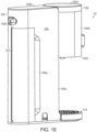
- the CO 2 cavity 104 can be closed off by a door 106, as seen in FIG. 1E .
- the door 106 can extend from the bottom side 102a upward and it can follow a contour of the left side 102c and into the back side 102f.
- the door 106 can be attached to the housing 102 by a means such as via a hinge or by magnets, or it can be mated using other techniques known in the art.
- the door 106 is wholly removable from the housing 102, but it can be secured to the housing in any of a variety of ways, e.g., by several magnets (not shown) disposed in the door 106 and in the housing 102.
- a cutaway 106a can be formed in the housing 102, which enables a user to grasp and remove the door 106 while maintaining a uniform shape of the overall housing 102.
- the door 106 can be moved between a closed position in which the CO 2 cavity 104 is closed off, and an open position in which the CO 2 cavity 104 is open. When the door 106 is in the open position, the CO 2 source is accessible.
- the CO 2 source is in the form of a canister 161, which will be described in more detail below.
- the housing 102 can include a drip tray 110, which can be seen in detail in FIGS. 2A-2B .
- the drip tray 110 extends from a lower portion of the front side 102e beneath the head assembly 120.
- the drip tray 110 can have any shape or form, and in the illustrated embodiment, it is flat and round while also corresponding to the size of the head assembly 120.
- the drip tray 110 can be integral with the housing 102, while in other embodiments it can be fully removable from the housing 102. Removing the drip tray 110, or not including a drip tray, may allow taller receiving vessels to fit under the head assembly 120. It may also allow for a shorter overall system 10' having a head assembly with a lower bottom, while still accommodating a same vessel height that can be accommodated with the system 10 and the drip tray 110.
- the illustrated drip tray 110 includes a trough 112 defining a central cavity 113, and a grate 114 placed atop the trough 112 and covering the central cavity 113.
- the grate 114 includes a plurality of holes.
- the trough 112 can act to catch and retain splashed or dripping fluid, which can pass through the holes in the grate 114 and can be collected within the central cavity 113.
- the drip tray 110 can be made of any material, similar to the housing 102, and it can be the same material or a different material as the housing.
- the trough 112 and the grate 114 can also be made from the same material or from different materials.
- the trough 112 and grate 114 can be removable from the housing to allow a user to discard any collected fluid.
- the system 110 may vent fluid into the drip tray 110 for various purposes, so that it can leave the system 10 as needed without resulting in a mess.
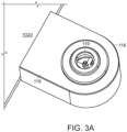
- FIGS. 3A-3B illustrate a reservoir valve seat 116 configured to couple the fluid reservoir 130 to the carbonation system.
- the illustrate reservoir valve seat 116 extends outward from the right side 102d of the housing 102 at the same level as the bottom side 102a. In this manner, the reservoir valve seat 116 can provide extra support to preventing tipping of the beverage dispensing device 10.
- the reservoir valve seat 116 can be located at the back side 102e, left side 102c, or in any other location.
- the reservoir valve seat 116 can be in the form of a hollow housing 118 having an upward extending valve 119.
- FIG. 3B also shows valve 119 coupled to water tubing 154 inside of the reservoir valve seat 116. This tubing 154 can allow fluid to be delivered to the carbonation assembly 150, which will be discussed later in more detail.
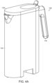
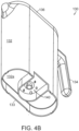
- FIGS. 4A-4B show a water reservoir 130 according to an illustrative embodiment.
- the water reservoir 130 generally, is a container for holding fluid, such as water, which can interface with the reservoir valve seat 116 to thereby enable fluid communication between the water reservoir 130 and the beverage dispensing device 10 for use in the creation and dispensing of beverages.
- the water reservoir 130 can have any shape, and it can be designed to complement the shape and size of the housing 102. For example, both the water reservoir 130 and the housing 102 can have flat sides to minimize the overall footprint of the system.
- the water reservoir 130 is shown in the form of a pitcher, and it has a main container 132, a handle 134, and a removable lid 136.
- a bottom side 132a of the container 130 is recessed, and a support 133 extends around the perimeter of the bottom side 132a.
- valve structure 140 On the bottom side 132a is a valve structure 140 which can be received by the upward extending valve 119 of the reservoir valve seat 116.
- the valve structure 140 includes a central plug 142 seated within a central valve silo 144.
- a valve guard 146 Surrounding an upper extent of the central plug 142, within the water reservoir 130, is a valve guard 146.
- the valve guard 146 is mounted to the water reservoir 130 and blocks off direct access to the central plug, while still allowing fluid to flow through the valve structure 140.
- the central plug 142 When not received on the upward extending valve 119, the central plug 142 is biased downward within the central valve silo 144 to a closed position to retain fluid in the water reservoir 130.
- the central plug 142 can be moved upward within the central valve silo 144 to an open position to allow fluid to flow from the water reservoir 130 through the valve structure 140 and into the rest of the beverage dispensing device 10.
- FIGS. 5A-5C illustrate an illustrative carbonation assembly 150.
- the carbonation assembly 150 can be contained within the housing 102, and it can be used to create carbonated water for use in beverages.
- the illustrated carbonation assembly 150 generally includes a water line 152, a gas line 160, and a mixing assembly 170.
- the mixing assembly 170 receives water from the water line 152 and gas (in the form of CO 2 ) from the gas line 160 in order to create carbonated water.
- the water line 152 is coupled to the water reservoir 130 and also can include any of: the valve structure 140, the valve seat 116, water tubing 154, a water pump 156, and a flow meter 157.
- the water tubing 154 runs from the valve seat 116 and through interior of the housing 102 to the mixing assembly 170.
- a first check valve 158a and a second check valve 158b can be disposed, which can selectively permit water flow into the mixing assembly 170 and prevent the backflow of water from the mixing assembly 170.
- a purging pump 159 Upstream from the second check valve 158b is a purging pump 159, which can be used to send pressurized air into the mixing assembly 170, in order to purge the mixing assembly 170 of still water and carbonated water between uses.
- a water pump 156 and a flow meter 157 can also be disposed in the water tubing 154 line.
- the water pump 156 operates to pump water out of the water reservoir 130, through the valve seat 116, through the water tubing 154, and into the mixing assembly 170.
- the flow meter 157 can measure the amount and/or rate of water passing through the water line 152 and into the mixing assembly 170 in order to accurately measure quantities needed for the creation of drinks.
- a flow meter 157 may not be used, and instead a sensor can be placed within the mixing assembly to gauge a total volume of fluid entering the mixing chamber 172.
- a sensor could be a float sensor or other means by which to gauge a volume.
- the gas line 160 can include any of: the CO 2 canister 161 or equivalent source, a regulator 164, a gas solenoid 166, and gas tubing 162.
- the gas tubing 162 runs from the CO 2 canister 161 to the mixing assembly 170.
- the gas line 160 can include a gas check valve 168 at the point of connection with the mixing assembly 170, which can selectively permit gas flow into the mixing assembly 170 and prevent backflow from the assembly 170 into the gas line 160.
- the CO 2 canister 161 sits within the CO 2 cavity 104 and can supply carbon-dioxide to the beverage dispensing device.
- the CO 2 canister 161 can be a replaceable unit containing pressurized carbon-dioxide, and when the canister 161 is empty, the canister 161 can be replaced in order to keep a supply of carbon-dioxide ready for future operation.
- the canister 161 can be connected to a regulator 164, which can lead to a gas solenoid 166 that is actuatable to open and close the passage of carbon-dioxide along the gas line 160 and into the mixing assembly 170.
- Both the water line 152 and the gas line 160 lead to the mixing assembly 170, which can be used to create carbonated water (or other fluid) from water (or other fluid) inputted via the water line 152 and the gas line 160.
- the mixing assembly 170 in the illustrated embodiment is disposed in the head assembly 120, and it can include a mixing chamber 172, an agitator 173, a motor 174, a dispenser valve 176, and a nozzle 178.
- the specific arrangement of the mixing assembly 170 can vary, and its relation to other components contained within the housing 102, as well as its relation to the housing 102, can vary as well.
- the agitator 173 is disposed within the mixing chamber 172
- the motor 174 is disposed beneath the mixing chamber 172.
- the dispenser valve 176 is located on an underside of the mixing chamber 172, which leads to the nozzle 178.
- the nozzle 178 can sit within the bottom side 120a of the head assembly 120 and can dispense carbonated and/or still water (or another fluid) for drinks.
- the mixing chamber 172 can include an emergency pressure relief valve 179, a pressure sensor 175a which can measure an internal pressure of the mixing chamber 172, and a temperature sensor 175b which can measure an internal temperature of the mixing chamber 172.
- the temperature sensor 175b can be an NTC, a thermistor, a thermocouple, or any other type of sensor capable of measuring temperature.
- the mixing chamber 172 can include a vent solenoid 172a and a back-pressure pressure relief valve 172b, which can each be actuated to regulate an internal pressure of the mixing chamber 172, for example, to release pressure from within the mixing chamber 172 at the end of a carbonation procedure, before dispensing the carbonated fluid. The carbonation procedure will be described in detail below.
- the carriage assembly 180 can retain at least one flavorant container 200 including a flavorant, which can be dispensed and combined with carbonated or uncarbonated water (or other fluid) to create flavored beverages.
- the carriage assembly 180 can be located within the head assembly 120, and it is shown having left and right carriages 182L, 182R, which can each retain a flavorant container 200L, 200R. In other embodiments, a different number of carriages can be used to retain a different number of flavorant containers.
- the left and right carriages 182L, 182R can be structurally the same but mirrored relative to each other, so description will only be provided for one carriage 182R.
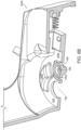
- the carriage 182R can be attached to the head assembly 120 via a pivotal hinge 183a and cam structure 183b arranged in a cam slot 183c, which allows the carriage to move between a raised and a lowered position. For example, as seen in FIG.
- the left carriage 182L is in the raised position and the right carriage 182R is in the lowered position.
- the flavorant container 200R can be inserted therein.
- the carriage assembly can further include a biasing element, such as a spring 183d, which can bias the carriage assembly to the raised position.
- the retention seat 184 On the carriage 182R itself is a retention seat 184, which is sized to seat the flavorant container 200R.
- the retention seat 184 can be in the form of a rounded depression that is shaped to receive a cap of a flavorant container.
- the retention seat can further include a keyed slot 184a extending from the rounded depression along a sidewall of the seat.
- the slot 184a can be sized to receive a complementary portion of the flavorant container in order to properly align the flavorant container 200 within the carriage 182R.
- the keyed slot 184a can also be generally referred to as an alignment channel.
- a retention catch 185 in the form of a spring-loaded extension configured to receive and retain a complimentary groove on the flavorant container 200.
- the retention seat 184 can also include retention projections 184b located within the slot, which provide more areas that a flavorant container 200 can frictionally fit when retained in the carriage 182R.
- retention projections 184b are shown in the form of rounded triangular shapes projecting outward from the retention seat 184, however the retention projections 184b can have any shape or form, for example, a form that conforms to a complimentary and compatible portion on a flavorant container (e.g., flavorant container 200 or 200', described below), or more specifically, a cap (e.g., 204, 204', described below) of a flavorant container.
- the retention-projections 184b can also serve as a means with which certain flavorant containers can be prevented from interfacing with the carriages 182L, 184R.
- the retention projections 184b can rise out of the retention seat 184 so that a flavorant container (e.g., flavorant container 200, 200') must have features amounting a complimentary and compatible pattern in order to be properly seated within the carriage (e.g., 182L, 182R), and consequently in order to be capable of properly dispensing flavorant.
- the complimentary and compatible pattern can be located on a cap of a flavorant container, as will be described in more detail below.
- a flavorant container without a complimentary pattern of retention projections 184b can be obstructed from properly interfacing with the carriage (e.g., 182L, 182R).
- the projection 184b and complimentary portions on a cap or other portion of a flavorant container may be constructed (e.g., machined) to have varying desired degrees of fit (e.g., tightness) when coupled together, which may take into account a desired tolerance of the parts.
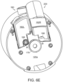
- the retention seat 184 can further include an inlet receiver 186 and an outlet receiver 188, which can align with an inlet 210 and an outlet 212 located on the flavorant container 200.
- the inlet receiver 186 features a circular gasket 186a which can seal around an inlet 210 in order to create an isolated path for air to flow into a seated consumable 200.
- Set within the carriage 182R and leading away from the inlet receiver 186 is an air line 189R, as seen especially in FIG. 6F .
- the air line 189R can extend through the hinge 183a of the carriage 182R and can eventually lead to an air pump 190R disposed within the head assembly 120.
- the air pump 190R can also be located elsewhere in the device 10, such as, for example, within the housing assembly 100.
- the air pump 190R is in fluid communication with the flavorant container 200 via the air line 189R and the inlet receiver 186.
- the outlet receiver 188 can be in the form of an opening which aligns with the outlet 212 and provides a pathway for the dispensing of a flavorant stored within the flavorant container 200.
- fluid When fluid is dispensed from a seated flavorant container 200, it can exit through the outlet 212 and pass through the outlet receiver 188, which is a simple opening. From there, the dispensed fluid can be received by a vessel, such as a drinking glass.
- a vessel such as a drinking glass.
- FIGS. 6H and 6I show the carriage assembly 180 with flavorant containers 200L, 200R retained therein.
- the carriages 182L, 182R are shown with respective air lines 189R, 189L extending upward and coupling with respective air pumps 190R, 190L.
- the air pumps 190R, 190L can be used to introduce pressurized air through the air lines 189R, 189L and into seated flavorant containers 200R, 200L, as will be described in greater detail below.
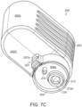
- FIGS. 7A-7F show one embodiment of the flavorant container 200.
- the flavorant container 200 is configured to contain a flavorant, which can be mixed with carbonated or uncarbonated water in order to create a flavored beverage.
- the illustrated flavorant container 200 includes a container body 202, a cap 204, and a foil seal (not shown).
- the container body 202 can have any shape, but in the illustrated embodiment, the container body 202 has the form of an extruded ovular shape.
- the container body 202 includes a base 202a, a sidewall 202b, and a top 202c.
- the sidewall 202b is shown with a plurality of ridges 203 formed therein, which can increase grip of the flavorant container 200 and/or provide structural reinforcement.
- an opening 206 In the top 202c and skewed off to one side is an opening 206, which leads to a hollow interior chamber 208 defined by the container body 202.
- the top 202c can be angled toward the opening 206 to aid in evacuation of the hollow interior chamber 208 during a dispensing operation.
- the flavorant Stored within the hollow interior chamber 208 is the flavorant, which can take on any form, such as a liquid, a syrup, a powder, a solid, or another compound.
- the cap 204 can be coupled to the container body 202 over the opening 206 to close off the hollow interior chamber 208.
- the cap 204 is snap-fitted to the container body 202, however any removable or irremovable coupling known in the art can be used, such as threads, welding, adhesives, or the like.
- the illustrated cap 204 can be round and can have a cylindrical outer wall 205 defining an opening therethrough.
- An end wall 204a extends across the opening and can be positioned at a mid-portion of the cylindrical outer wall 205.
- On an external surface of the cap 204 and surrounding the outlet 212 can be a collar 218, which can act to provide the outlet with increased structure, as well as to provide the carriage assembly with an easier point of contact when the flavorant container is retained therein.
- an alignment tab 207 Disposed on an outer side of the cap 204 can be an alignment tab 207, which can protrude radially outward from the cap 204 and extend along a length of the cap.
- the alignment tab 207 can enable proper alignment and orientation with the carriage assembly, as explained above.
- the alignment tab can include a clip detail 207a, which can couple with the retention catch 185 in order to retain the consumable 200 within the carriage assembly 180.
- the cap 204 can also include an inlet 210 and an outlet 212 positioned in the end wall 204a.
- the inlet 210 can be in the form of a generally hollow elongate tubular projecting from opposed sides of the end wall 204a, and the inlet 210 can have a diameter that is less than, greater than, or equal to a diameter of the outlet 212.
- the cap 204 including the inlet 210 and the outlet 212 can be arranged and designed to be accommodated by a carriage (e.g., carriage 182L, 182R), such as by having protruding portions located on the cap 204 which correspond and compliment features on the carriage, such as the retention projections 184b.
- a carriage e.g., carriage 182L, 182R
- the inlet 210 can take the form of a cylindrical extension protruding from the end wall 204a of the cap 204, and on an interior portion of the cap 204 locating within the interior chamber 208, the inlet 210 can include an inlet valve 214 to allow for the inflow of fluid through the cap 204 and into the hollow interior chamber 208.
- the inlet valve 214 is shown in FIG. 7E in the form of a duckbill valve, but any suitable form of a valve could be used.
- the inlet 210 therefore can form a cylindrical inlet pathway 216, and, due to the shape and structure of the inlet 210, the cylindrical inlet pathway 216 can have a radius R 1 which is smaller in the external portion of the cap 204 than a radius R 2 in the internal portion of the cap 204.
- the outlet 212 likewise can include a hollow tubular structure in the form of a collar 218 that extends outward from the end wall 204a; however the outlet 212 can be significantly shorter and larger than the inlet 210.
- the outlet 212 can include a valve 212a extending thereacross that is biased to a closed configuration, however the valve can be configured to open when a pressure differential across the outlet 212 exceeds a predetermined pressure.
- valve 212a is shown to be positioned slightly inward relative to the end wall 204a when the valve 212a is in a neutral position, but it can be positioned to be even with or slightly outward of the end wall 204a.
- the valve 212a is a cross-slit valve, however any suitable type of valve could be used.
- inlet valve 214 and the inlet pathway 216 are shown in FIGS. 7D and 7E extending beyond the outer rim 205, they can also have a shorter form so as to be recessed more within the cap 204. This can enable the outer rim 205 to protect the inlet valve 214 and the inlet pathway 216, as well as the inlet 210 generally, during transportation, handling, and use.
- the flavorant container 200 can also include a plug seal (not shown), which can be disposed between the container 202 and the cap 204 to aid in sealing the hollow inner chamber 208.
- the plug seal can be especially useful if the hollow inner chamber 208 has an increased interior pressure, such as during a dispensing operation.
- the foil seal (not shown) can adhere to an upper extent of the outer wall 205 to cover the entirety of the cap 204, including the inlet 210 and the outlet 212. In this way, the foil seal can hermetically seal the flavorant to prolong shelf-stability and maintain freshness.
- the foil seal can also cover only the inlet 210 and/or the outlet 212.
- the foil seal can be peeled off by a user prior to a first use.
- the flavorant container 200 can be made from a variety of materials, including plastics, resins, metals, rubbers, and more. These materials can feature environmentally-friendly materials such as, for example, reclaimed and recycled plastics, fibers, and other materials known in the art, in order to limit waste production resulting from operation of the beverage dispensing device 10.
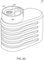
- FIG. 8A-8D depict various embodiments of the flavorant container 200.
- the illustrative embodiments can include similar features and characteristics as the flavorant container 200, and as such, to avoid being needlessly redundant, descriptions may not be repeated.
- a flavorant container 200' including a cap 204'.
- the cap 204' further includes an alignment pattern 220'.
- the alignment pattern 220' can take the form of protrusions located on the cap 204', which can include or be separate from the collar 218' or other features described above.
- the alignment pattern 220' takes the form of a figure-eight shape, which is shown as essentially linked collars around both the inlet 210' and the outlet 212'.
- the carriage e.g., carriages 182L, 182R
- the carriage can have a cavity with a complimentary figure-eight shaped depression that receives the alignment pattern 220' on the container.
- the depression can be defined at least in part by the retention projections 184b, as explained above, such that the depression and the pattern can be complimentary to each other.
- the inclusion of this alignment pattern 220' can allow for further stability when retaining the flavorant container 200' within the carriage assembly 180.
- the alignment pattern 220' can also take the form of indentations or any other surface features that aid in aligning the flavorant container with the carriage (e.g., carriages 182L, 182R), while also preventing the alignment and retention of other types of containers which may lack complimentary features.
- FIG. 8B depicts an illustrative embodiment of a flavorant container 200" including a container 202" and a cap 204".
- the cap 204" can have an inlet 210" and an outlet 212" angled relative to each other. Consequently, when the flavorant container 200" is seated in a carriage (e.g., carriage 182L, 182R), and flavorant is dispensed therefrom, the flavorant can be emitted from the outlet 212" at an angle relative to a dispensing stream of fluid (e.g., carbonated water) from the nozzle 178. In this way, the flavorant and fluid dispensed from the nozzle 178 can mix in-flight, rather than in a disposed receptacle, such as a drinking glass.
- fluid e.g., carbonated water
- FIGS. 8C and 8D depict an illustrative embodiment of a flavorant container 200"' having separate openings for an inlet 210"' and an outlet 212"'. These separate openings are delineated as an inlet opening 206a"' and an outlet opening 206b"', which are each disposed in the container 202′′′.
- the inlet opening 206a"' and the outlet opening 206b′′′ can be covered by a single cap 204"', as seen in FIG. 8D , or by separate inlet and outlet caps 204a′′′, 204b′′′, respectively.
- flavor containers 200, 200', 200", and 200′′′ are depicted with specific features and arrangements of features, however the features and arrangements of features described herein can be applicable to and interchangeable with any embodiment.
- a UI 300 which can be used to operate the beverage dispensing device 10.
- the UI 300 can be used to interface with a controller (not shown).
- the UI 300 is shown located on the head assembly 120; however, it could be located anywhere on the beverage dispensing device 10, such as on the housing 102. Further, the beverage dispensing device 10 could also be operated remotely, such as through a remote application on a computer, smart phone, or other similar device.
- the UI 300 can receive inputs to operate and control aspects of a creation process for a beverage.
- a user can select and control parameters of the beverage they desire, such as liquid volume, carbonation level, flavor choice, and flavor strength.
- Liquid volume pertains to the overall size of the drink.
- Carbonation level pertains to the amount of carbon-dioxide dissolved in the water, which affects how "bubbly" the drink is.
- Flavor choice pertains to the type of flavorant added to the beverage, e.g., lemon, lime, etc.
- Flavor strength pertains to the amount of flavorant added to the beverage.
- the UI 300 is shown having a central display 302 in the form a circular screen.
- the central display 302 can also operate as a dial to move between options.
- indicators 304 which can light up and correspond to what a user selects at the central display.
- FIG. 9 depicted in FIG. 9 above the central display 302 is an indicator 304a pertaining to carbonation level.
- the indicator 304a is labeled "sparkling" and features an image of bubbles.
- the indicator 304a also includes a meter, which is lit up according to the carbonation level selected by the user.
- Flavor strength is associated with indicator 304b, the words “flavor strength,” and an image of a slice of citrus fruit.
- Flavor type is shown with indicator 304c as being either a "1" or a "2,” which correspond to a selection between a left flavorant container and a right flavorant container.
- the previously described components of the beverage dispensing device 10 can operate together to create and dispense custom beverages.
- preparing a beverage with the beverage dispensing device 10 can involve several processes, including water preparation, gas preparation, flavorant container preparation, and customization at the UI 300. With these preparations and customizations complete, the beverage dispensing device 10 can then operate to mix and dispense carbonated water and flavorant as desired.
- Water preparation can include filling the water reservoir 130 with water and then seating the water reservoir 130 onto the valve seat 116. This ensures that the water within the water reservoir 130 is now ready to be drawn upon during a carbonation procedure.
- Gas preparation can involve adding or replacing the CO 2 canister 161 within the CO 2 cavity 104 when the canister has run out. This can require the door 106 to be opened and a new canister 161 to be hooked up to the gas regulator in order to enable carbon-dioxide within the canister 161 to be used during a carbonation procedure.
- Loading a flavorant container 200 into the carriage assembly 180 will allow for a flavorant stored within the flavorant container 200 to be added to the beverage in order to provide flavor.
- the carriage 182 can be moved to the lowered position by applying a force to the carriage 182 to overcome the spring-biased maintaining the carriage assembly in the raised position, and the flavorant container 200 can be oriented so that all features of the cap 204 align within the retention seat 184.
- the alignment tab 207 can be slid down into the keyed slot 184a, such that the retention catch 185 clicks into place and secures the flavorant container 200.
- the inlet 210 can be received by the inlet receiver, which creates an air-tight seal around the inlet 210.
- the outlet 212 can be aligned with the outlet receiver, which positions the outlet 212 over the opening in preparation for the dispensing of a flavorant. Once the flavorant container 200 is secured in the carriage 182, the carriage 182 can be moved to the raised position. A second flavorant can likewise be added to the other carriage assembly.
- the alignment pattern 220' can be further relied upon to guide the flavorant container 200' into position within the carriage assembly 180d.
- a vessel such as a drinking glass
- a vessel can be placed upon the drip tray 110 beneath the nozzle 178 and the outlet receiver 188 of the carriage assembly 180.
- aspects of the beverage can be selected, including fluid volume, carbonation level, flavor type, and flavor strength.
- Fluid volume can be selected by a user in preset sizes, such as, for example, 8 fluid ounces, 10 fluid ounces, 12 fluid ounces, and the like. Fluid volume can also be precisely selected by a user to even include fractional fluid ounces, or can be selected to operate in another unit, such as milliliters and the like.
- the UI 300 can prompt the user for the next input.
- Carbonation level can be selected by a user in preset sizes, which can be presented as levels to the user, such as 0-5, where a "0" can refer to no carbonation and a "5" refers to the maximum amount of carbonation dissolvable in the water. Other levels of carbonation can be assigned to the numbers presented, or the numbers presented can vary, i.e., a user is presented with a 1-10 instead of a 0-5.
- Flavor type can be selected to offer a choice between a flavorant container stored in the left carriage 182L and a flavorant container stored in the right carriage 182R. A choice can also be made by a user to skip flavor selection if an unflavored beverage is desired, or the user may be able to select both the left and right flavorant containers 200L, 200R.
- Flavor strength can be selected by a user to customize the amount of flavorant dispensed from the flavorant container 200. More flavorant will lead to a stronger drink. In some embodiments, if both the left and right flavorant containers 200L, 200R are selected to dispense a flavorant, the flavor strength can be individually selected for each of the flavorant containers 200L, 200R, resulting in potentially the same amount of each flavorant or a different amount of each flavorant.
- the beverage dispensing device 10 can determine a default amount of flavorant to be added based on a selected fluid volume and/or a selected carbonation level. The user can accept the default amount of flavorant, or they can also change the default amount of flavorant to a custom amount.
- a user can select a "start" button to begin the dispensing process.
- the central display 302 can act as a start button, and in other embodiments, the start button can be located elsewhere on the beverage dispensing device 10, or on a remote application.
- the inputs are presented here in a certain order, a user may be able to input them in any order desired, or may also be able to select only some of the inputs before initiating the dispensing process. For example, a user can select options to dispense a drink omitting one or all of the selections, or even can omit carbonation and/or flavoring altogether.
- the beverage dispensing device 10 When a user has initiated the dispensing process, the beverage dispensing device 10 will coordinate several processes together in order to properly create and dispense the desired beverage. These processes can include a mixing process and/or a flavoring process, for example, depending on user selection.
- the mixing process generally involves the mixing assembly 170 receiving water through the water line 152 and carbon-dioxide through the gas line 160, mixing the received water and carbon-dioxide under pressure to create carbonated water, and dispensing carbonated water through the nozzle 178.
- based on the user-selected fluid volume and carbonation level corresponding amounts water and carbon-dioxide will be pumped and/or vented into the mixing chamber 172.
- the mixing chamber 172 has a finite volume, which can limit the amount of carbonated water that can be made in a single batch, and so if a user selected fluid-volume exceeds the volume of the mixing chamber 172, more than one batch can be made to reach the total desired volume.
- the mixing chamber 172 can produce six fluid-ounces of carbonated water in a single batch.
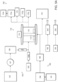
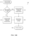
- FIGS. 10A-10E depict an illustrative control process 400, as well as sub-processes 410, 430, 450, and 470, which can be followed to create and dispense a carbonated flavored beverage.
- the process 400 and sub-processes 410, 430, 450, and 470 can vary, and, for example, may include additional sub-processes or omit sub-processes. Additionally, any and all of the sub-processes 410, 430, 450, and 470 can vary to add or omit individual steps.
- the illustrative beverage-making process 400 starts at starting point 402 and proceeds through several sub-processes as shown in FIG. 10A . These sub-processes can include an illustrative initialization process 410, an illustrative user input process 430, an illustrative carbonation process 450, and an illustrative flavoring process 470.
- a beverage can be dispensed at 490.
- FIG. 10B depicts an illustrative initialization sub-process 410, which can be used to prepare the beverage dispensing system 10.
- the sub-process can run separately from, or concurrently with, other sub-processes or processes.
- the sub-process 410 can begin at block 411 and proceed to block 412.
- the system 10 can determine whether there is enough water present in the water reservoir 130. If the system 10 determines that there is not enough water present in the water reservoir 130, the sub-process 410 can continue to block 413, where the system 10 can prompt a user to supply water to the water reservoir 130.
- the system 10 can also prevent drink creation until the system 10 determines that water has been supplied.
- the sub-process 410 can continue to block 414.
- the system 10 can run a check to determine whether a user desires carbonation in a beverage. As explained above, the system 10 via UI 300 can receive a user input determining a carbonation level. If the user has indicated that they want carbonation in a beverage, a check can be performed at block 414 before the sub-process 410 proceeds to block 415. At block 15, the system 10 can check to see if there is enough carbon-dioxide in the gas source, for example, in canister 162, before allowing a beverage dispensing process to proceed.
- the system 10 can prompt a user to refill the carbon-dioxide source. If, at 415, the system 10 detects that there is enough carbon-dioxide available, the sub-process 410 can continue to block 417. Referring again to block 414, if a user has indicated that they do not want carbonation in a beverage, the sub-process 410 can proceed directly to block 417 and skip the check at block 415. At block 417, the system 10 can run a check to determine whether a user desires flavor. This check can be based on a user input received at UI 300, for example.
- the sub-process 410 can finish. If, at block 417, the system 10 determines a user does not want flavoring, the sub-process 410 can finish. If, at block 417, the system 10 determines a user does want flavoring, the system can run a check at block 418 to see if enough flavoring is available to flavor a beverage. If the system 10 determines that there is not enough flavoring available, the system 10 can prompt a user to refill flavoring and, until flavoring is refilled, prevent drink creation which attempts to use flavoring. If the system 10 determines that there is enough flavoring, the system can 10 finish the initialization sub-process 410.
- process 400 can proceed to user input process 430.
- some of sub-process 410 can be informed by inputs received at a UI 300, which can occur during user input process 430. Accordingly, sub-process 410 may not necessarily finish before user input process 430 begins.
- FIG. 10C depicts an illustrative user input sub-process 430.
- a user can be prompted for an input or inputs, which can result in a customized beverage dispensed from beverage dispensing device 10 based at least partially on the received input or inputs.
- the inputs can be received in any order, and some inputs may be added in addition to what is described. Further, inputs may be skipped.
- an input can be received for a liquid volume of a dispensed drink.
- the received input could be representative of several options, such as, for example, 6 oz., 8 oz., 10 oz., etc., or the received input could be representative of sizes, such as small, medium, or large.
- an input can be received for a carbonation level of a dispensed drink. As explained previously, this user could be prompted to enter a carbonation level between 0-5, where "0" represents no carbonation and "5" represents maximum carbonation.
- a received input at block 436 can be informative of other processes and checks run by the system, such as the check performed at 414 of sub-process 410, for example.
- an input can be received representing a type of flavor.
- the system 10 can hold at least one flavorant container 200, as explained above, and in some embodiments, it can hold at least two flavorant containers 200.
- a user input can be received at 438, which selects between a first or a second flavorant container held in the system 10.
- a user input can also be received that selects both the first and second flavorant container 200, or no flavorant container 200. Similar to the operation at block 436 for a carbonation level, if a user input at 438 is received that indicates no flavor is desired, flavoring protocols and operations can be skipped. At block 440, a user input can be received indicating a flavorant strength. Depending on the input received, the system 10 can dispense more or less flavorant from a flavorant container 200. If a user input is received at block 438 that flavorant is not desired, block 440 can be skipped.
- FIG. 10D depicts an illustrative carbonation sub-process 450, which can occur if a user has indicated that they would like some level of carbonation in their beverage, as shown in block 452.
- the sub-process 450 can continue to block 454.
- water can be pumped into the mixing chamber 172 by the water pump 156 via the water line 152, based on a user-selected fluid volume, as explained previously.
- the flow meter 157 can measure the amount of water flowing through the water line 152, and water volume can be determined by pumping for a set amount of time and measuring a flow rate with the flow meter 157.
- the vent solenoid 172a then can close.
- gas e.g., carbon-dioxide
- the gas solenoid 166 can be actuated and regulated carbon-dioxide can be allowed to flow into the mixing chamber 172.
- the agitator 173 can be powered on to begin to churn the water and the carbon-dioxide within the mixing chamber 172.
- the agitator 173 can run longer than the time that carbon-dioxide flows into the mixing chamber 173, for example, for between five and ten seconds after.
- Mixing can occur within the mixing chamber 172, and then, at block 460, the pressure relief valve 179 can open to release excess pressure in the mixing chamber 172.
- the dispensing valve 177 can be opened to allow the newly created carbonated water to exit the mixing chamber 172 and be dispensed by the nozzle 178. If, at block 464, more carbonated water is needed, the carbonation sub-process 450 can proceed back to block 454, and carbonation can occur again until the total volume desired has been dispensed. If no more carbonated water is required, the sub-process 450 can proceed to block 468, indicating that the sub-process 450 is complete.
- the mixing chamber can be ventilated through actuation of a pressure release valve 179. If an internal temperature is measured by the temperature sensor 175b that exceeds a safe threshold, the mixing chamber can be ventilated as well.
- a safe threshold e.g. 100 psi
- a purging pump 159 coupled to the mixing assembly 170 can introduce pressurized air into the mixing chamber 172 to clear it out of excess fluid.
- the pressurized air can be introduced through a check valve 158b, permitting one-way flow into the mixing chamber 172.
- FIG. 10E depicts an illustrative flavoring sub-process 470, which can occur if a user has indicated that they would like flavoring in their beverage, as shown in block 472.
- the flavoring process generally involves introducing pressurized air into a flavorant container (e.g., flavorant container 200) to force a flavorant to dispense from the flavorant container. Based on a user selection, a flavorant can be selectively dispensed by the system 10. At block 747 of sub-process 470, this can be presented as a choice between a flavorant container 200 seated in the left carriage 182L and a flavorant container seated in the right carriage 182R.
- a flavorant container e.g., flavorant container 200
- the air pump 190 can be in fluid communication with the inlet 210.
- the air pump 190 will send pressurized air down the air line 189 and into the inlet 210.
- the introduction of pressurized air will force the duckbill valve to open, and, as a result, an internal pressure of the hollow interior chamber 208 will increase.
- the outlet 212 will open and a flavorant will be forced out of the outlet 212, out of the head assembly 120, and into a placed vessel (e.g., a drinking glass).
- the amount of flavorant dispensed depends on the amount of pressurized air forced into the hollow interior chamber 208.
- This amount of pressurized air is dependent upon the input received at the UI 300 from a user indicating their desired flavor level.
- This dispensing process can be seen in the remainder of sub-process 470, which includes blocks 476 and 480 if a user selects a left container 200, and which includes blocks 478 and 480 if a user selects a right container 200.
- the sub-process can be completed at block 482.
- the flavoring sub-process 470 can be coordinated with the carbonation sub-process 450, such that carbonated water and a flavorant can be dispensed at the same time.
- the carbonated water and the flavorant are dispensed substantially parallel to each other, such that they mix in a placed drinking glass.
- the carbonated water and the flavorant are dispensed such that their flow paths collide in mid-air, above the drinking glass. In this way, the carbonated water and the flavorant can begin to mix in midair, which can result in a more thoroughly mixed beverage.
- the flavorant can be dispensed along with uncarbonated water to form an uncarbonated flavor beverage.
- the injection of air through the inlet 210 can be accomplished through a single burst of at least one pressurized gas, or through several bursts of at least one pressurized gas.
- a flavoring sub-process can take a short time, e.g., less than one second. In some embodiments, the process can be less than 250ms, and in some embodiments, as low as approximately 130ms.
- FIG. 11 depicts an illustrative dispensing process 500, including an example time sequence for various operations within the dispensing process 500.
- the process 500 can begin at block 501 and proceed to block 502.
- the mixing chamber 172 can be filled to a specified volume. For example, if the mixing chamber 172 has a maximum capacity of 6 oz. and a user has selected a volume less than 6 oz., the selected volume will be pumped into the mixing chamber 172. If the user has selected a volume greater than 6 oz., then 6 oz. can be pumped into the mixing chamber 172 during a first operation.
- carbon-dioxide can be supplied to the mixing chamber 172, and at block 510, supply of carbon-dioxide can end.
- the motor 174 can be activated to drive the agitator 173 within the mixing chamber 172, and at block 510, the motor 174 can be deactivated.
- the block 504-508 link can occur for a first period of time, and the 506-510 link can occur for a second period of time that is different than the first period of time.
- the first period of time and the second period of time may occur in succession, or they may occur in parallel - either fully in parallel or partially in parallel.
- each of the first and second periods of time can operate at a LOW cycle, a MED cycle, and a HIGH cycle.
- the first period of time can be three seconds and the second period of time can be 2 seconds.
- the first period of time can be four seconds and the second period of time can be eight seconds.
- the first period of time can be six seconds and the second period of time can be ten seconds.
- the process 500 can continue to block 512.
- the mixing chamber 172 can be ventilated for a time before the mixing chamber 172 is sealed again at block 514.
- the mixing chamber 172 can be vented for various times as needed to reduce an internal pressure of the mixing chamber 172, and in an illustrative example, the mixing chamber 172 can be vented for approximately 3.2 seconds.
- the mixing chamber 172 can dispense stored fluid via the outlet valve 176.
- the purging pump 159 can be activated to assist in dispensing stored fluid from the mixing chamber 172. This dispensing operation can take time depending on the amount of stored fluid to be ventilated, and in an illustrative example can take approximately twelve seconds.
- the outlet valve 176 can be closed, and at block 522, the purging pump 159 can be deactivated. If a volume of fluid is required which exceeds the maximum capacity of the mixing chamber, the process 500 can begin again at block 501 as is necessary to produce and dispense the desired volume.
- an air pump e.g., air pump 190L, 190R, etc.
- the air pump can be deactivated to end the flavorant dispensing process.
- the time the air pump is activated between block 524 and block 526 can vary, depending on an amount of flavorant to be dispensed. For example, if LOW flavor is desired, the time can be approximately one second; if MED flavor is desired, the time can be approximately 1.2 seconds; if HIGH flavor is desired, the time can be approximately 1.4 seconds.
- the flavorant dispensing process depicted in blocks 524 and 526 can operate in parallel with or in succession with any other portion of the dispensing process 500.
- the flavorant container 200 can be made using various manufacturing processes.
- the container 202 can be made by a first process and the cap 204 can be made by a second process.
- the first process can include manufacturing the container 202 through Extrusion Blow Molding. This could be accomplished with polypropylene (PP) and/or could involve injection molding and blow molding, either separately or in combination.
- An orientation feature can be used to ensure that a cap 204 is fitted in a desired orientation.
- the second process can include manufacturing the cap 204 through injection molding.
- a first orientation feature can be used to ensure a desired alignment relative to the container 202.
- a second orientation feature can be used to ensure correct placement during a manufacturing process (e.g., the first process, the second process, or another process).
- a third orientation feature can be used to provide a correct orientation when the flavorant container 200 is placed within the carriage assembly 180.
- a latching feature such as the alignment tab 207, can be included to ensure that the flavorant container 204 can be secured within the carriage assembly 180.
- the inlet 210 and the outlet 212 can also be included for the reasons stated above.
- the inlet 210 can include a silicone duckbill valve, an umbrella valve, or other types of valves.
- the outlet 212 can include a silicone dispense valve, a cross-slit valve, or other types of valves.
- the cap 204 including the inlet 210 and the outlet 212, can be a single, discrete element.
- the valves associated with the inlet 210 and/or 212 can be made from other materials known to those skilled in the art as well, including other molded flexible materials, including various plastics, rubbers, and others.
- Approximating language may be applied to modify any quantitative representation that could permissibly vary without resulting in a change in the basic function to which it is related. Accordingly, a value modified by a term or terms, such as “about,” “approximately,” and “substantially,” are not to be limited to the precise value specified. In at least some instances, the approximating language may correspond to the precision of an instrument for measuring the value.
- range limitations may be combined and/or interchanged, such ranges are identified and include all the sub-ranges contained therein unless context or language indicates otherwise.
Landscapes
- Engineering & Computer Science (AREA)
- Food Science & Technology (AREA)
- Chemical & Material Sciences (AREA)
- Chemical Kinetics & Catalysis (AREA)
- Health & Medical Sciences (AREA)
- Nutrition Science (AREA)
- Life Sciences & Earth Sciences (AREA)
- Polymers & Plastics (AREA)
- Devices For Dispensing Beverages (AREA)
Abstract
Description
- A system for dispensing carbonated and/or flavored beverages is provided.
- Conventional beverage dispensing devices operate to carbonate and/or flavor water. Some devices may mix carbonated water and a flavoring compound together in a machine and then dispense the resulting mixture into a receptacle. Unless the devices are thoroughly cleaned, this method can result in contamination occurring over time. Other devices rely on crushing, puncturing, and/or generally compromising flavoring containers in order to access the flavoring compounds inside. These methods of breaching flavoring containers can result in splatter and mess, which, if not thoroughly cleaned, can result in similar contamination.
- Still other devices rely on carbonating water within a specialized container to be attached to the device, and from which the resulting beverage is served. The container can be pre-filled with water and/or flavoring, and then it can be secured to the devices and pressurized within the container and used to serve the resulting beverage. These devices, however, can create excess plastic waste, as specially adapted bottles must be produced to interface with the device.
- Accordingly, there remains a need to provide a better beverage dispensing device to improve on mess creation and waste production.
- A beverage system for preparing a flavored and/or carbonated beverage is provided. Related apparatuses and techniques are also provided.
- In one embodiment, a beverage system for preparing a flavored carbonated beverage is provided. The beverage system can have a housing. The housing can include a fluid input configured to receive a first fluid from a fluid source and a fluid output configured to emit a second fluid. A carriage assembly can be movably mounted on the housing. The carriage assembly can include a cavity configured to seat a flavorant container. The cavity can have a port configured to interact with an inlet on the flavorant container to allow a pump in the housing to at least one gas from the port through inlet into the flavorant container.
- One or more of the following features can be included in any feasible combination. For example, the at least one gas can include air.
- In another example, the first fluid and the second fluid can be the same.
- In another example, the first fluid can be water.
- In another example, the housing can include a mixing chamber configured to fluidly communicate with the fluid source, and the housing can be configured to coupled to a pressurized gas source to allow a gas to be delivered to the mixing chamber to carbonate the first fluid within the mixing chamber to produce the second fluid.
- In another example, the beverage system can include a pump and a conduit coupled to the pump and the port. The pump can be configured to force air along a path. The path can include the conduit, the port, and the inlet into the flavorant container.
- In another example, the cavity can include an alignment channel formed in and extending along a sidewall thereof. The cavity can be configured to receive a corresponding projection on a flavorant container to align the flavorant container with the port.
- In another example, the cavity can include a hole formed therein and configured to receive a projection on the flavorant container, and the cavity can also include at least one projection extending from a surface thereon and configured to extend into a portion of the flavorant container. In other aspects, the portion can be a cap affixed to a main body of the flavorant container.
- In another example, the carriage assembly can be movable between an open configuration to receive a flavorant container, and a closed position in which the carriage assembly prevents removal of the flavorant container. In certain aspects, the carriage assembly can be pivotally coupled to the housing by a hinge and can be movable between the open and closed positions about the hinge.
- In another example, the carriage assembly can include first and second independently movable carriages for seating first and second flavorant containers.
- In another example, the housing is configured to emit the second fluid in a first stream to emit flavorant in a second stream, and wherein the second fluid and the emitted flavorant form the beverage. In other aspects, the first stream and the second stream are substantially parallel. In still other aspects, the second scream can have a trajectory at an oblique angle from a trajectory of the first stream. The second stream can combine with the first stream in-flight. In further aspects, the housing can include a mixing chamber in fluid communication with the fluid source and coupled to a pressurized gas source to allow a gas to be delivered to the mixing chamber to carbonate the first fluid within the mixing chamber to produce the second fluid.
- In another example, the beverage system can include a removable pitcher coupled to the housing and having the water reservoir therein.
- In another example, the cavity can include a first cavity, and the carriage assembly can include a second cavity configured to seat a second flavorant container. In certain aspects, the beverage system can include a user interface configured to receive at least one input. The at least one input can characterize a selection between emitting flavorant from the first flavor container and emitting flavorant from the second flavorant container.
- In another example, the port can be configured to create a vacuum seal around the inlet when the flavorant container is seated in the cavity.
- In another example, the cavity can include at least one projection defining a retention pattern. The retention pattern can be configured to receive a complimentary feature on a flavorant container. In other aspects, the retention pattern can comprise a figure-eight pattern. In further aspects, the complimentary feature on the flavorant container can include two circles of different diameters separated by a space.
- In another embodiment, a beverage system for preparing a flavored carbonated beverage is provided. The beverage system can include a fluid dispenser configured to dispense carbonated water and a carriage assembly movably mounted to the fluid dispenser. The carriage assembly can be configured to fixedly seat at least one flavorant container. The fluid dispenser can include an air pump capable of injecting at least one gas into a flavorant container seated in the carriage assembly to cause the at least one flavorant container to dispense flavorant. The carriage assembly can be configured to create a vacuum seal around at least part of the flavorant container before injecting the at least one gas into the flavorant container.
- One or more of the following features can be included in any feasible combination. For example, the at least one gas can include air.
- In another example, the first fluid can include water.
- In another example, the carriage assembly can be configured to seat a plurality of flavorant containers.
- In another example, the carriage assembly can have a cavity formed therein and can be configured to receive the flavorant container. The carriage assembly can have a channel extending along a sidewall of the cavity and configured to receive a projection on the flavorant container.
- In another example, the carriage assembly can include an outlet port formed therein and can be configured to couple to an inlet port on a flavorant container for allowing air to be injected into the flavorant container.
- In another example, the carriage assembly can include an outlet port formed therein and can be configured to couple to an outlet port on a flavorant container to allow the first fluid within the flavorant container to be ejected from the flavorant container. The outlet port in the carriage assembly can be configured to deliver fluid to a receptacle.
- In another embodiment, a flavorant container for use in a beverage carbonation system is provided. The flavorant container can include a container defining an interior hollow chamber. The container can have an opening leading to the interior hollow chamber. The flavorant container can also include a cap coupled to the opening of the container. The cap can have an inlet valve that can be sealed to retain fluid within the container and that can be configured to open in response to pressurize air to allow air to be injected into the interior hollow chamber. The cap can also have an outlet valve that can be sealed to retain fluid within the container and that can be configured to open when a pressure within the interior hollow chamber exceeds a predetermine threshold pressure to allow fluid within the container to flow out through the outlet valve.
- One or more of the following features can be included in any feasible combination. For example, the inlet valve can define a first flow path and the outlet valve can define a second flow path. The first flow path and the second flow path can be substantially parallel to each other.
- In another example, the inlet valve can define a first flow path and the outlet valve can define a second flow path. The first flow path and the second flow path can be angled toward each other.
- In another example, the cap can include a first raised collar extending around the inlet valve and a second raised collar extending around the outlet valve. In other aspects, the first raised collar and the second raised collar can at least partially overlap in a figure-eight pattern.
- In another example, the cap can include at least one protrusion. The at least one protrusion can be configured to be received by a complimentary retention pattern in a beverage dispensing device.
- In another example, the inlet valve can have a first diameter and the outlet valve can have a second diameter. The first diameter can be smaller than the second diameter.
- In another example, the cap can include an alignment mechanism configured to orient the cap within a carriage. In certain aspects, the alignment mechanism can comprise a protrusion extending along an exterior surface of the cap.
- In another example, the container can be substantially rigid to resist deformation.
- In another example, the container can include a plurality of ridges disposed in a sidewall thereof.
- In another example, the inlet valve can be a duckbill valve.
- In another example, the cap can include an end wall extending across the opening to the interior hollow chamber. The outlet valve can be positioned within the interior hollow chamber inward of the end wall.
- In another example, the outlet valve can be recessed within a raised collar.
- In another example, the container can have an oblong configuration and the cap is offset from a mid-portion of the container.
- In another embodiment, a flavorant container is provided. The flavorant container can include a container defining an interior hollow chamber. The container can have an opening leading to the interior hollow chamber configured to contain a liquid. The flavorant container can also include an exchange assembly fixedly coupled to and projecting from an upper surface of the container and disposed over the opening. The exchange assembly can be configured to seal the interior hollow chamber, and the exchange assembly can include an inlet valve positioned within the interior hollow chamber, an outlet valve, and at least one projection formed thereon. The at least one projection can be configured to aid in alignment of the exchange assembly into a carriage in a beverage carbonation system. The interior hollow chamber can be configured to receive pressurized air through the inlet valve, and the interior hollow chamber can be configured to expel fluid through the outlet valve in response to receiving pressurized air through the inlet valve.
- One or more of the following features can be included in any feasible combination. For example, the exchange assembly can include a cap having a hollow cylindrical body with an end wall positioned within the hollow cylindrical body. The inlet and outlet valves can extend across the end wall. In other aspects, the end wall can be positioned across a substantial mid-portion of the exchange assembly.
- In another example, the inlet valve can define a first flow path and the outlet valve can define a second flow path. The first flow path and the second flow path can be substantially parallel to each other.
- In another example, the container can be substantially rigid to resist deformation.
- In another example, the inlet valve can be a duckbill valve.
- In another example, the exchange assembly can includes a first collar disposed around the inlet valve and a second collar disposed around the outlet valve. In other aspects, the first collar and the second collar can at least partially overlap in a figure-eight pattern.
- In another example, the container can include a plurality of ridges disposed on a sidewall thereof.
- In another example, the exchange assembly can be a discrete element. In other aspects, the exchange assembly can be formed by an injection molding process.
- In another embodiment, a beverage system for preparing a flavored carbonated beverage is provided. The beverage system can include a housing having a mixing chamber. The housing can be configured to operably couple to a fluid reservoir and a pressurized gas source, and the housing can have a flavorant system configured to operably couple to a flavorant container. The beverage system can also include a processor disposed in the housing and configured to cause, in response to at least one input, a first fluid to be delivered from the fluid source into the mixing chamber and a second fluid to be delivered from the mixing chamber to a receptacle. The processor can also be configured to cause pressurized air to be delivered into the flavorant container to cause a flavorant within the flavorant container to be ejected into the receptacle. Flavorant can be delivered to the container separate from and simultaneously with the carbonated fluid to form a flavored carbonated beverage.
- One or more of the following features can be included in any feasible combination. For example, the flavorant can be delivered to the receptacle concurrently to the second fluid being delivered to the receptacle.
- In another example, the first fluid and the second fluid can be the same.
- In another example, the processor can be configured to cause, in response to the at least one input, gas to be delivered from the pressurized gas source into the mixing chamber to form the second fluid as a carbonated fluid.
- In another example, the flavorant can be delivered to the container along a first flow path that is spaced apart from a second flow path of the carbonated fluid being delivered to the container. In other aspects, the first flow path and the second flow path are substantially parallel. In still other aspects, the first flow path is angled toward the second flow path.
- In another example, the input can characterize an amount of carbonation to be delivered to the mixing chamber. In other aspects, the amount of carbonation to be delivered is zero.
- In another example, the input can characterize an amount of flavorant to be delivered to the receptacle.
- In another example, the housing can include a carriage configured to removably seat the flavorant container.
- In another example, the flavorant container can include a first flavorant container. The flavorant system can be configured to operably couple to a second flavorant container. In other aspects, the processor can be configured to receive an input indicating a selection of one of the first and second flavorant containers, and the processor can be configured to cause, in response to the input, pressurized air to be delivered into the selected one of the first and second flavorant containers.
- In another example, the flavorant container can include an inlet valve and and outlet valve. Pressurized air can be delivered through the inlet valve and the flavorant can be ejected through the outlet valve.
- In another embodiment, a carbonated beverage system is provided. The carbonated beverage system can include a housing. The housing can include a mixing chamber fluidly coupled to a fluid reservoir and to a pressurized gas source. The mixing chamber can be configured to receive a first fluid from the mixing chamber and deliver a second fluid to a first fluid outlet on the housing. The housing can also include a flavorant receptacle. The flavorant receptacle can be configured to seat a flavorant container such that the flavorant container is configured to receive pressurized air from a pump in the housing and is configured to deliver flavorant to a second fluid outlet on the housing. The second fluid outlet can be spaced apart from the first fluid outlet, and the first and second fluid outlets can be positioned above a platform configured to support a beverage container.
- One or more of the following features can be included in any feasible combination. For example, the second fluid can be the first fluid.
- In another example, the first fluid outlet can be configured to deliver the second fluid concurrently with the second fluid outlet delivering flavorant.
- In another example, the first and second fluid outlets can define fluid flow paths that are substantially parallel to one another.
- In another example, the second fluid outlet can define a fluid flow path that extends transverse to a fluid flow path defined by the first fluid outlet such that flavorant flowing from the second fluid outlet is directed into a path of carbonated fluid flowing from the first outlet.
- In another example, the fluid reservoir can be a water pitcher removably coupled to the mixing chamber.
- In another example, the housing can include a user interface configured to receive at least one input. The at least one input can control at least one characteristic of the carbonated fluid. In other aspects, the at least one characteristic can be at least one of a fluid volume and a carbonation level.
- In another embodiment, a method for preparing a flavored carbonated beverage is provided. The method can include receiving at a processor an input from a user and, in response to the input, causing gas from a pressurized gas source to be delivered into a mixing chamber containing a fluid to thereby form a carbonated fluid. The method can also include causing the carbonated fluid to be delivered into a container, and causing a flavorant to be delivered into the container along a fluid flow path that is spaced apart from and substantially parallel to a fluid flow path of the carbonated fluid being delivered into the container.
- One or more of the following features can be included in any feasible combination. For example, the at least one input can characterize at least one of a flavor type, a carbonation level, a volume of carbonated fluid to be delivered into the container, and a volume of flavorant to be delivered into the container.
- In another example, the method can include, in response to the input, causing a fluid from a fluid storage tank to be delivered into the mixing chamber. In other aspects, the fluid storage tank can be a water pitcher removably coupled to the mixing chamber.
- In another example, the method can include seating a flavorant container containing the flavorant in a carriage assembly.
- The details of one or more variations of the subject matter described herein are set forth in the accompanying drawings and the description below. Other features and advantages of the subject matter described herein will be apparent from the description and drawings, and from the claims.
- These and other features will be more readily understood from the following detailed description taken in conjunction with the accompanying drawings, in which:
-
FIG. 1A is a front view of one embodiment of a beverage dispensing device having a water reservoir coupled thereto; -
FIG. 1B is a front perspective view of the beverage dispensing device ofFIG. 1A , having the water reservoir removed; -
FIG. 1C is a bottom perspective view of the beverage dispensing device ofFIG. 1B ; -
FIG. 1D is a rear perspective view of the beverage dispensing device ofFIG. 1B , having a door open to reveal a CO2 cavity; -
FIG. 1E is a rear perspective view of the beverage dispensing device ofFIG. 1B with a door removed to reveal a CO2 canister disposed within a canister cavity; -
FIG. 2A is a front perspective view of a drip tray of the beverage dispensing device ofFIG. 1A ; -
FIG. 2B is a front perspective view of the drip tray ofFIG. 2A having a grate removed; -
FIG. 3A is a front perspective view of a reservoir valve seat of the beverage dispensing device ofFIG. 1A ; -
FIG. 3B is a side perspective cross-sectional view of the reservoir valve seat ofFIG. 3A ; -
FIG. 4A is a front perspective view of the water reservoir ofFIG. 1A ; -
FIG. 4B is a bottom perspective view of the water reservoir ofFIG. 1A ; -
FIG. 4C is a side cross-sectional view of a valve section of the water reservoir ofFIG. 1A ; -
FIG. 5A is a system diagram of the beverage dispensing device ofFIG. 1A , having a carbonation assembly; -
FIG. 5B is a left side view of the carbonation assembly ofFIG. 5A , including a mixing assembly, according to some embodiments; -
FIG. 5C is a left side view of the mixing assembly ofFIG. 5B ; -
FIG. 6A is a front perspective view of a carriage assembly used with the beverage dispensing device ofFIG. 1A , according to some embodiments; -
FIG. 6B is a left cross-sectional view of a carriage of the carriage assembly ofFIG. 6A ; -
FIG. 6C is a left cross-sectional view of the carriage assembly ofFIG. 6A ; -
FIG. 6D is a side perspective cross-sectional view of the carriage assembly ofFIG. 6A ; -
FIG. 6E is a bottom perspective view of the carriage assembly ofFIG. 6A ; -
FIG. 6F is a side cross-sectional view of a flavorant container seated on the carriage assembly ofFIG. 6A , showing an air line of the carriage assembly; -
FIG. 6G is a perspective view of the carriage assembly ofFIG. 6A , having two flavorant containers seated thereon, according to some embodiments; -
FIG. 6H is a cross-sectional view of the carriage assembly ofFIG. 6A , having air pumps attached to air lines; -
FIG. 6I is a left perspective view of the carriage assembly ofFIG. 6H ; -
FIG. 7A is a perspective view of one embodiment of a flavorant container; -
FIG. 7B is a perspective view of the flavorant container ofFIG. 7A without a cap; -
FIG. 7C is a perspective view of the flavorant container ofFIG. 7A ; -
FIG. 7D is a side cross-sectional view of the flavorant container ofFIG. 7A ; -
FIG. 7E is a side cross-sectional view of a cap of the flavorant container ofFIG. 7A , according to some embodiments; -
FIG. 8A is a perspective view of a flavorant container according to another embodiment; -
FIG. 8B is a cross-sectional view of a flavorant container according to another embodiment, having an inlet and an outlet angled relative to one another; -
FIG. 8C is an exploded perspective view of a flavorant container having a separate inlet and outlet opening in a container, and a lid configured to cover the inlet and the outlet; -
FIG. 8D is an exploded right side view of the flavorant container ofFIG. 8C having a separate inlet lid and outlet lid; -
FIG. 9 is a front view of a user interface of a beverage dispensing device according to an embodiment; -
FIG. 10A is a system process diagram for an illustrative control process; -
FIG. 10B is a system process diagram for an illustrative initialization sub-process for the control process ofFIG. 10A ; -
FIG. 10C is a system process diagram for an illustrative user input sub-process for the control process ofFIG. 10A ; -
FIG. 10D is a system process diagram for an illustrative carbonation sub-process for the control process ofFIG. 10A ; -
FIG. 10E is a system process diagram for an illustrative flavoring sub-process for the control process ofFIG. 10A ; -
FIG. 11 is a system process diagram for an illustrative carbonation and flavoring sub-process. - It is noted that the drawings are not necessarily to scale. The drawings are intended to depict only typical aspects of the subject matter disclosed herein, and therefore should not be considered as limiting the scope of the disclosure.
- Certain illustrative embodiments will now be described to provide an overall understanding of the principles of the structure, function, manufacture, and use of the devices and methods disclosed herein. One or more examples of these embodiments are illustrated in the accompanying drawings. Those skilled in the art will understand that the devices and methods specifically described herein and illustrated in the accompanying drawings are non-limiting illustrative embodiments and that the scope of the present invention is defined solely by the claims. The features illustrated or described in connection with one illustrative embodiment may be combined with the features of other embodiments. Such modifications and variations are intended to be included within the scope of the present invention.
- Further, in the present disclosure, like-named components of the embodiments generally have similar features, and thus within a particular embodiment each feature of each like-named component is not necessarily fully elaborated upon. Additionally, to the extent that linear or circular dimensions are used in the description of the disclosed systems, devices, and methods, such dimensions are not intended to limit the types of shapes that can be used in conjunction with such systems, devices, and methods. A person skilled in the art will recognize that an equivalent to such linear and circular dimensions can easily be determined for any geometric shape.
- A beverage dispensing device is provided that can carbonate and/or flavor, and dispense beverages. The device can receive user inputs at a user interface, and these inputs can include customization options for creating a beverage, including fluid volume, carbonation level, flavor type, and flavor strength. When the inputs are received, a carbonation system can create carbonated water using water sourced from a water reservoir (or other source) coupled to the device and carbon-dioxide sourced from a carbon-dioxide canister (or other source) coupled to the device. The amounts of water (or other fluid) and carbon-dioxide to be used to create the beverage can be determined based on the received user inputs. The device can also receive one or more flavorant containers at a carriage assembly, each of which can be selected for dispensing by a user in order to flavor the newly-created carbonated water. During a dispensing process, pressurized air can be introduced into a flavorant container via an inlet, and flavorant can be ejected via an outlet. The carbonated water and the flavorant can be ejected from separate nozzles into a drinking glass (or other receiving vessel, e.g., a travel mug) where they are mixed together. In other embodiments, the beverage can contain uncarbonated water and a flavorant to form an uncarbonated flavored beverage. In some embodiments, the flavorant may be dispensed at an angle relative to the flow of the dispensed carbonated water so that the carbonated water and flavorant are combined in flight before reaching the drinking glass.
- With reference now to
FIGS. 1A-1E , an illustrative embodiment of abeverage dispensing device 10 is shown. The illustratedbeverage dispensing device 10 generally includes ahousing assembly 100 having a carbonation assembly (not shown) disposed therein, acarriage assembly 180 configured to hold one or moreflavorant containers 200, and a controller (also referred to as a processor, not shown) with a user interface (UI) 300 for receiving instructions from a user. Afluid reservoir 130 is coupled to thehousing assembly 100 and is configured to contain a fluid to be delivered to the carbonation assembly. Thehousing assembly 100 can also include adrip tray 110 configured to support a container, such as a glass, for collecting fluid. In operation, a user can provide various inputs to the UI and thebeverage dispensing device 10 can dispense a carbonated or uncarbonated water, as may be desired, and optionally a flavorant to flavor the carbonated or uncarbonated fluid. - As shown in
FIGS. 1A-1E , the illustratedhousing assembly 100 includes ahousing 102 having an elongate, upright hollow body with top and bottom ends 102a, 102b, aleft side 102c, aright side 102d, afront side 102e, and aback side 102f. In the illustrated embodiment, the housing is oblong, and the shape of thehousing 102 is longer from thefront side 102e to theback side 102f than it is from theleft side 102c to theright side 102d. Thefront side 102e is shown having a flat facade, and theback side 102f is shown having a rounded convex facade, while each of the left andright sides housing 102 can have any shape, and as such, in various embodiments, the shape of thehousing 102 can vary to include additional rounded or flat components, or other forms beyond what is shown. Thehousing 102 can be sized to fit internal components of thebeverage dispensing device 10, discussed in further detail below. Thehousing 102 can be made of any suitable material or materials, and can include various metals (e.g., stainless steel, aluminum), plastics, glass, or other suitable materials known to those skilled in the art, alone or in combination. - The bottom side of the
housing 102 can provide thebeverage dispensing device 10 with a flat base, and the bottom side can include supports orfeet 103 which can provide additional stability. Thefeet 103 can be in any form, and in one embodiment, as shown inFIG. 1C , the feet are elongate and are disposed around an outer edge of thebottom side 102a. To prevent thehousing 102 from sliding on a surface, thefeet 103 can be made from a higher-friction material, such as rubber, or have a portion of a higher-friction - As further shown, the
housing 102 includes ahead assembly 120 located on an upper portion of thefront side 102e of thehousing 102. Thehead assembly 120 can be substantially cylindrical in shape, and includes atop side 120a which aligns with thetop side 102b of thehousing 102, and abottom side 120c which includes various openings for dispensing fluids used in the creation of drinks. Between thetop side 120a and thebottom side 120c is anouter surface 120b, which defines the rounded form of thecylindrical head assembly 120. Thehead assembly 120 can contain components of a mixing assembly configured to carbonate fluids (e.g., water), which can then be dispensed from the bottom side. Further, thehead assembly 120 can be configured to receive one or moreflavorant containers 180, which can be utilized in the creation of beverages. Theouter surface 120b of thehead assembly 120 can includeUI 300 for receiving inputs for operating the device. The mixing assembly, dispensing of fluids, and the creation of beverages, including through operation of theUI 300, will be discussed in greater detail below. -
FIG. 1D shows a CO2 cavity 104 according to the illustrated embodiment. The CO2 cavity 104 is an opening in the housing, which can receive a CO2 source used in carbonation processes. In the illustrated embodiment, the CO2 cavity 104 is located in the rearleft side 102c of thehousing 102, although the CO2 cavity 104 can be in other locations. The CO2 cavity 104 can be closed off by a door 106, as seen inFIG. 1E . The door 106 can extend from thebottom side 102a upward and it can follow a contour of theleft side 102c and into theback side 102f. The door 106 can be attached to thehousing 102 by a means such as via a hinge or by magnets, or it can be mated using other techniques known in the art. In the illustrated embodiment, the door 106 is wholly removable from thehousing 102, but it can be secured to the housing in any of a variety of ways, e.g., by several magnets (not shown) disposed in the door 106 and in thehousing 102. Acutaway 106a can be formed in thehousing 102, which enables a user to grasp and remove the door 106 while maintaining a uniform shape of theoverall housing 102. - The door 106 can be moved between a closed position in which the CO2 cavity 104 is closed off, and an open position in which the CO2 cavity 104 is open. When the door 106 is in the open position, the CO2 source is accessible. In the illustrated embodiment, the CO2 source is in the form of a
canister 161, which will be described in more detail below. - As introduced above, the
housing 102 can include adrip tray 110, which can be seen in detail inFIGS. 2A-2B . Thedrip tray 110 extends from a lower portion of thefront side 102e beneath thehead assembly 120. Thedrip tray 110 can have any shape or form, and in the illustrated embodiment, it is flat and round while also corresponding to the size of thehead assembly 120. In some embodiments, thedrip tray 110 can be integral with thehousing 102, while in other embodiments it can be fully removable from thehousing 102. Removing thedrip tray 110, or not including a drip tray, may allow taller receiving vessels to fit under thehead assembly 120. It may also allow for a shorter overall system 10' having a head assembly with a lower bottom, while still accommodating a same vessel height that can be accommodated with thesystem 10 and thedrip tray 110. - The illustrated
drip tray 110 includes atrough 112 defining acentral cavity 113, and agrate 114 placed atop thetrough 112 and covering thecentral cavity 113. Thegrate 114 includes a plurality of holes. During operation of thebeverage dispensing device 10, thetrough 112 can act to catch and retain splashed or dripping fluid, which can pass through the holes in thegrate 114 and can be collected within thecentral cavity 113. Thedrip tray 110 can be made of any material, similar to thehousing 102, and it can be the same material or a different material as the housing. Thetrough 112 and thegrate 114 can also be made from the same material or from different materials. Thetrough 112 and grate 114 can be removable from the housing to allow a user to discard any collected fluid. In some embodiments, thesystem 110 may vent fluid into thedrip tray 110 for various purposes, so that it can leave thesystem 10 as needed without resulting in a mess. - As indicated above, the
fluid reservoir 130 can be coupled to thehousing 100 for storing fluid to be delivered into the carbonation system.FIGS. 3A-3B illustrate areservoir valve seat 116 configured to couple thefluid reservoir 130 to the carbonation system. The illustratereservoir valve seat 116 extends outward from theright side 102d of thehousing 102 at the same level as thebottom side 102a. In this manner, thereservoir valve seat 116 can provide extra support to preventing tipping of thebeverage dispensing device 10. In other embodiments, thereservoir valve seat 116 can be located at theback side 102e,left side 102c, or in any other location. Thereservoir valve seat 116 can be in the form of ahollow housing 118 having an upward extendingvalve 119. The upward extendingvalve 119 can be received by a corresponding valve structure located on the bottom side of a water reservoir.FIG. 3B also showsvalve 119 coupled towater tubing 154 inside of thereservoir valve seat 116. Thistubing 154 can allow fluid to be delivered to thecarbonation assembly 150, which will be discussed later in more detail. -
FIGS. 4A-4B show awater reservoir 130 according to an illustrative embodiment. Thewater reservoir 130, generally, is a container for holding fluid, such as water, which can interface with thereservoir valve seat 116 to thereby enable fluid communication between thewater reservoir 130 and thebeverage dispensing device 10 for use in the creation and dispensing of beverages. Thewater reservoir 130 can have any shape, and it can be designed to complement the shape and size of thehousing 102. For example, both thewater reservoir 130 and thehousing 102 can have flat sides to minimize the overall footprint of the system. In the illustrated embodiment, thewater reservoir 130 is shown in the form of a pitcher, and it has amain container 132, ahandle 134, and aremovable lid 136. Abottom side 132a of thecontainer 130 is recessed, and asupport 133 extends around the perimeter of thebottom side 132a. - On the
bottom side 132a is avalve structure 140 which can be received by the upward extendingvalve 119 of thereservoir valve seat 116. Thevalve structure 140 includes acentral plug 142 seated within acentral valve silo 144. Surrounding an upper extent of thecentral plug 142, within thewater reservoir 130, is avalve guard 146. Thevalve guard 146 is mounted to thewater reservoir 130 and blocks off direct access to the central plug, while still allowing fluid to flow through thevalve structure 140. When not received on the upward extendingvalve 119, thecentral plug 142 is biased downward within thecentral valve silo 144 to a closed position to retain fluid in thewater reservoir 130. When thevalve structure 140 is received on the upward extendingvalve 119, thecentral plug 142 can be moved upward within thecentral valve silo 144 to an open position to allow fluid to flow from thewater reservoir 130 through thevalve structure 140 and into the rest of thebeverage dispensing device 10. -
FIGS. 5A-5C illustrate anillustrative carbonation assembly 150. Thecarbonation assembly 150 can be contained within thehousing 102, and it can be used to create carbonated water for use in beverages. The illustratedcarbonation assembly 150 generally includes awater line 152, agas line 160, and a mixingassembly 170. The mixingassembly 170 receives water from thewater line 152 and gas (in the form of CO2) from thegas line 160 in order to create carbonated water. - The
water line 152 is coupled to thewater reservoir 130 and also can include any of: thevalve structure 140, thevalve seat 116,water tubing 154, awater pump 156, and aflow meter 157. Thewater tubing 154 runs from thevalve seat 116 and through interior of thehousing 102 to the mixingassembly 170. Near the point of connection to the mixing assembly, afirst check valve 158a and asecond check valve 158b can be disposed, which can selectively permit water flow into the mixingassembly 170 and prevent the backflow of water from the mixingassembly 170. Upstream from thesecond check valve 158b is a purgingpump 159, which can be used to send pressurized air into the mixingassembly 170, in order to purge the mixingassembly 170 of still water and carbonated water between uses. Awater pump 156 and aflow meter 157 can also be disposed in thewater tubing 154 line. Thewater pump 156 operates to pump water out of thewater reservoir 130, through thevalve seat 116, through thewater tubing 154, and into the mixingassembly 170. Theflow meter 157 can measure the amount and/or rate of water passing through thewater line 152 and into the mixingassembly 170 in order to accurately measure quantities needed for the creation of drinks. In various embodiments, aflow meter 157 may not be used, and instead a sensor can be placed within the mixing assembly to gauge a total volume of fluid entering the mixingchamber 172. Such a sensor could be a float sensor or other means by which to gauge a volume. - The
gas line 160 can include any of: the CO2 canister 161 or equivalent source, aregulator 164, agas solenoid 166, andgas tubing 162. Thegas tubing 162 runs from the CO2 canister 161 to the mixingassembly 170. Similar to thewater line 152, thegas line 160 can include agas check valve 168 at the point of connection with the mixingassembly 170, which can selectively permit gas flow into the mixingassembly 170 and prevent backflow from theassembly 170 into thegas line 160. As mentioned above, the CO2 canister 161 sits within the CO2 cavity 104 and can supply carbon-dioxide to the beverage dispensing device. The CO2 canister 161 can be a replaceable unit containing pressurized carbon-dioxide, and when thecanister 161 is empty, thecanister 161 can be replaced in order to keep a supply of carbon-dioxide ready for future operation. Thecanister 161 can be connected to aregulator 164, which can lead to agas solenoid 166 that is actuatable to open and close the passage of carbon-dioxide along thegas line 160 and into the mixingassembly 170. - Both the
water line 152 and thegas line 160 lead to the mixingassembly 170, which can be used to create carbonated water (or other fluid) from water (or other fluid) inputted via thewater line 152 and thegas line 160. The mixingassembly 170 in the illustrated embodiment is disposed in thehead assembly 120, and it can include a mixingchamber 172, anagitator 173, amotor 174, adispenser valve 176, and anozzle 178. The specific arrangement of the mixingassembly 170 can vary, and its relation to other components contained within thehousing 102, as well as its relation to thehousing 102, can vary as well. In the illustrated embodiment, theagitator 173 is disposed within the mixingchamber 172, and themotor 174 is disposed beneath the mixingchamber 172. Thedispenser valve 176 is located on an underside of the mixingchamber 172, which leads to thenozzle 178. Thenozzle 178 can sit within thebottom side 120a of thehead assembly 120 and can dispense carbonated and/or still water (or another fluid) for drinks. - The mixing
chamber 172 can include an emergencypressure relief valve 179, apressure sensor 175a which can measure an internal pressure of the mixingchamber 172, and atemperature sensor 175b which can measure an internal temperature of the mixingchamber 172. Thetemperature sensor 175b can be an NTC, a thermistor, a thermocouple, or any other type of sensor capable of measuring temperature. Additionally, the mixingchamber 172 can include avent solenoid 172a and a back-pressurepressure relief valve 172b, which can each be actuated to regulate an internal pressure of the mixingchamber 172, for example, to release pressure from within the mixingchamber 172 at the end of a carbonation procedure, before dispensing the carbonated fluid. The carbonation procedure will be described in detail below. - With reference now to
FIGS. 6A-6I , acarriage assembly 180 and aflavorant container 200 are shown according to one embodiment. Thecarriage assembly 180 can retain at least oneflavorant container 200 including a flavorant, which can be dispensed and combined with carbonated or uncarbonated water (or other fluid) to create flavored beverages. - The
carriage assembly 180 can be located within thehead assembly 120, and it is shown having left andright carriages flavorant container right carriages carriage 182R. Thecarriage 182R can be attached to thehead assembly 120 via apivotal hinge 183a andcam structure 183b arranged in acam slot 183c, which allows the carriage to move between a raised and a lowered position. For example, as seen inFIG. 6A , theleft carriage 182L is in the raised position and theright carriage 182R is in the lowered position. When thecarriage 182R is in the lowered position, theflavorant container 200R can be inserted therein. The carriage assembly can further include a biasing element, such as aspring 183d, which can bias the carriage assembly to the raised position. - On the
carriage 182R itself is aretention seat 184, which is sized to seat theflavorant container 200R. Theretention seat 184 can be in the form of a rounded depression that is shaped to receive a cap of a flavorant container. The retention seat can further include akeyed slot 184a extending from the rounded depression along a sidewall of the seat. Theslot 184a can be sized to receive a complementary portion of the flavorant container in order to properly align theflavorant container 200 within thecarriage 182R. Thekeyed slot 184a can also be generally referred to as an alignment channel. Within thekeyed slot 184a, there can be aretention catch 185 in the form of a spring-loaded extension configured to receive and retain a complimentary groove on theflavorant container 200. Theretention seat 184 can also includeretention projections 184b located within the slot, which provide more areas that aflavorant container 200 can frictionally fit when retained in thecarriage 182R. InFIGS. 6A and6B ,retention projections 184b are shown in the form of rounded triangular shapes projecting outward from theretention seat 184, however theretention projections 184b can have any shape or form, for example, a form that conforms to a complimentary and compatible portion on a flavorant container (e.g.,flavorant container 200 or 200', described below), or more specifically, a cap (e.g., 204, 204', described below) of a flavorant container. The retention-projections 184b can also serve as a means with which certain flavorant containers can be prevented from interfacing with thecarriages 182L, 184R. Theretention projections 184b can rise out of theretention seat 184 so that a flavorant container (e.g.,flavorant container 200, 200') must have features amounting a complimentary and compatible pattern in order to be properly seated within the carriage (e.g., 182L, 182R), and consequently in order to be capable of properly dispensing flavorant. The complimentary and compatible pattern can be located on a cap of a flavorant container, as will be described in more detail below. A flavorant container without a complimentary pattern ofretention projections 184b can be obstructed from properly interfacing with the carriage (e.g., 182L, 182R). Theprojection 184b and complimentary portions on a cap or other portion of a flavorant container may be constructed (e.g., machined) to have varying desired degrees of fit (e.g., tightness) when coupled together, which may take into account a desired tolerance of the parts. - The
retention seat 184 can further include aninlet receiver 186 and anoutlet receiver 188, which can align with aninlet 210 and anoutlet 212 located on theflavorant container 200. Theinlet receiver 186 features acircular gasket 186a which can seal around aninlet 210 in order to create an isolated path for air to flow into a seatedconsumable 200. Set within thecarriage 182R and leading away from theinlet receiver 186 is anair line 189R, as seen especially inFIG. 6F . Theair line 189R can extend through thehinge 183a of thecarriage 182R and can eventually lead to anair pump 190R disposed within thehead assembly 120. Theair pump 190R can also be located elsewhere in thedevice 10, such as, for example, within thehousing assembly 100. In this way, when the flavorant container is seated on thecarriage 182R, theair pump 190R is in fluid communication with theflavorant container 200 via theair line 189R and theinlet receiver 186. Theoutlet receiver 188 can be in the form of an opening which aligns with theoutlet 212 and provides a pathway for the dispensing of a flavorant stored within theflavorant container 200. When fluid is dispensed from a seatedflavorant container 200, it can exit through theoutlet 212 and pass through theoutlet receiver 188, which is a simple opening. From there, the dispensed fluid can be received by a vessel, such as a drinking glass. The seating and dispensing process will be described below in greater detail. -
FIGS. 6H and6I show thecarriage assembly 180 withflavorant containers carriages respective air lines respective air pumps air pumps air lines flavorant containers - FIGS. 7A-7F show one embodiment of the
flavorant container 200. Theflavorant container 200 is configured to contain a flavorant, which can be mixed with carbonated or uncarbonated water in order to create a flavored beverage. - The illustrated
flavorant container 200 includes acontainer body 202, acap 204, and a foil seal (not shown). Thecontainer body 202 can have any shape, but in the illustrated embodiment, thecontainer body 202 has the form of an extruded ovular shape. Thecontainer body 202 includes abase 202a, asidewall 202b, and a top 202c. Thesidewall 202b is shown with a plurality ofridges 203 formed therein, which can increase grip of theflavorant container 200 and/or provide structural reinforcement. In the top 202c and skewed off to one side is anopening 206, which leads to a hollowinterior chamber 208 defined by thecontainer body 202. The top 202c can be angled toward theopening 206 to aid in evacuation of the hollowinterior chamber 208 during a dispensing operation. Stored within the hollowinterior chamber 208 is the flavorant, which can take on any form, such as a liquid, a syrup, a powder, a solid, or another compound. - The
cap 204 can be coupled to thecontainer body 202 over theopening 206 to close off the hollowinterior chamber 208. In the illustrated embodiment, thecap 204 is snap-fitted to thecontainer body 202, however any removable or irremovable coupling known in the art can be used, such as threads, welding, adhesives, or the like. The illustratedcap 204 can be round and can have a cylindricalouter wall 205 defining an opening therethrough. Anend wall 204a extends across the opening and can be positioned at a mid-portion of the cylindricalouter wall 205. On an external surface of thecap 204 and surrounding theoutlet 212 can be acollar 218, which can act to provide the outlet with increased structure, as well as to provide the carriage assembly with an easier point of contact when the flavorant container is retained therein. Disposed on an outer side of thecap 204 can be analignment tab 207, which can protrude radially outward from thecap 204 and extend along a length of the cap. Thealignment tab 207 can enable proper alignment and orientation with the carriage assembly, as explained above. The alignment tab can include aclip detail 207a, which can couple with theretention catch 185 in order to retain the consumable 200 within thecarriage assembly 180. Thecap 204 can also include aninlet 210 and anoutlet 212 positioned in theend wall 204a. Theinlet 210 can be in the form of a generally hollow elongate tubular projecting from opposed sides of theend wall 204a, and theinlet 210 can have a diameter that is less than, greater than, or equal to a diameter of theoutlet 212. Thecap 204, including theinlet 210 and theoutlet 212 can be arranged and designed to be accommodated by a carriage (e.g.,carriage cap 204 which correspond and compliment features on the carriage, such as theretention projections 184b. - On an external portion of the
cap 204, facing away from the hollowinterior chamber 208, theinlet 210 can take the form of a cylindrical extension protruding from theend wall 204a of thecap 204, and on an interior portion of thecap 204 locating within theinterior chamber 208, theinlet 210 can include aninlet valve 214 to allow for the inflow of fluid through thecap 204 and into the hollowinterior chamber 208. Theinlet valve 214 is shown inFIG. 7E in the form of a duckbill valve, but any suitable form of a valve could be used. Theinlet 210 therefore can form acylindrical inlet pathway 216, and, due to the shape and structure of theinlet 210, thecylindrical inlet pathway 216 can have a radius R1 which is smaller in the external portion of thecap 204 than a radius R2 in the internal portion of thecap 204. Theoutlet 212 likewise can include a hollow tubular structure in the form of acollar 218 that extends outward from theend wall 204a; however theoutlet 212 can be significantly shorter and larger than theinlet 210. Theoutlet 212 can include avalve 212a extending thereacross that is biased to a closed configuration, however the valve can be configured to open when a pressure differential across theoutlet 212 exceeds a predetermined pressure. Thevalve 212a is shown to be positioned slightly inward relative to theend wall 204a when thevalve 212a is in a neutral position, but it can be positioned to be even with or slightly outward of theend wall 204a. In the illustrated embodiment, thevalve 212a is a cross-slit valve, however any suitable type of valve could be used. - While the
inlet valve 214 and theinlet pathway 216 are shown inFIGS. 7D and7E extending beyond theouter rim 205, they can also have a shorter form so as to be recessed more within thecap 204. This can enable theouter rim 205 to protect theinlet valve 214 and theinlet pathway 216, as well as theinlet 210 generally, during transportation, handling, and use. - The
flavorant container 200 can also include a plug seal (not shown), which can be disposed between thecontainer 202 and thecap 204 to aid in sealing the hollowinner chamber 208. The plug seal can be especially useful if the hollowinner chamber 208 has an increased interior pressure, such as during a dispensing operation. - The foil seal (not shown) can adhere to an upper extent of the
outer wall 205 to cover the entirety of thecap 204, including theinlet 210 and theoutlet 212. In this way, the foil seal can hermetically seal the flavorant to prolong shelf-stability and maintain freshness. The foil seal can also cover only theinlet 210 and/or theoutlet 212. The foil seal can be peeled off by a user prior to a first use. - The
flavorant container 200 can be made from a variety of materials, including plastics, resins, metals, rubbers, and more. These materials can feature environmentally-friendly materials such as, for example, reclaimed and recycled plastics, fibers, and other materials known in the art, in order to limit waste production resulting from operation of thebeverage dispensing device 10. -
FIG. 8A-8D depict various embodiments of theflavorant container 200. The illustrative embodiments can include similar features and characteristics as theflavorant container 200, and as such, to avoid being needlessly redundant, descriptions may not be repeated. In the illustrative embodiment ofFIG. 8A , a flavorant container 200' including a cap 204'. The cap 204' further includes an alignment pattern 220'. The alignment pattern 220' can take the form of protrusions located on the cap 204', which can include or be separate from the collar 218' or other features described above. The alignment pattern 220', as depicted, takes the form of a figure-eight shape, which is shown as essentially linked collars around both the inlet 210' and the outlet 212'. The carriage (e.g.,carriages retention projections 184b, as explained above, such that the depression and the pattern can be complimentary to each other. The inclusion of this alignment pattern 220' can allow for further stability when retaining the flavorant container 200' within thecarriage assembly 180. The alignment pattern 220' can also take the form of indentations or any other surface features that aid in aligning the flavorant container with the carriage (e.g.,carriages -
FIG. 8B depicts an illustrative embodiment of aflavorant container 200" including acontainer 202" and acap 204". Thecap 204" can have aninlet 210" and anoutlet 212" angled relative to each other. Consequently, when theflavorant container 200" is seated in a carriage (e.g.,carriage outlet 212" at an angle relative to a dispensing stream of fluid (e.g., carbonated water) from thenozzle 178. In this way, the flavorant and fluid dispensed from thenozzle 178 can mix in-flight, rather than in a disposed receptacle, such as a drinking glass. -
FIGS. 8C and8D depict an illustrative embodiment of aflavorant container 200"' having separate openings for aninlet 210"' and anoutlet 212"'. These separate openings are delineated as aninlet opening 206a"' and anoutlet opening 206b"', which are each disposed in thecontainer 202‴. Theinlet opening 206a"' and theoutlet opening 206b‴ can be covered by asingle cap 204"', as seen inFIG. 8D , or by separate inlet andoutlet caps 204a‴, 204b‴, respectively. - The illustrative embodiments of the
flavor containers - With reference now to
FIG. 9 , aUI 300 is shown which can be used to operate thebeverage dispensing device 10. TheUI 300 can be used to interface with a controller (not shown). TheUI 300 is shown located on thehead assembly 120; however, it could be located anywhere on thebeverage dispensing device 10, such as on thehousing 102. Further, thebeverage dispensing device 10 could also be operated remotely, such as through a remote application on a computer, smart phone, or other similar device. - The
UI 300 can receive inputs to operate and control aspects of a creation process for a beverage. For example, a user can select and control parameters of the beverage they desire, such as liquid volume, carbonation level, flavor choice, and flavor strength. Liquid volume pertains to the overall size of the drink. Carbonation level pertains to the amount of carbon-dioxide dissolved in the water, which affects how "bubbly" the drink is. Flavor choice pertains to the type of flavorant added to the beverage, e.g., lemon, lime, etc. Flavor strength pertains to the amount of flavorant added to the beverage. - The
UI 300 is shown having acentral display 302 in the form a circular screen. Thecentral display 302 can also operate as a dial to move between options. Above and below thecentral display 302 are indicators 304, which can light up and correspond to what a user selects at the central display. For example, depicted inFIG. 9 above thecentral display 302 is anindicator 304a pertaining to carbonation level. Theindicator 304a is labeled "sparkling" and features an image of bubbles. Theindicator 304a also includes a meter, which is lit up according to the carbonation level selected by the user. If the user selects the maximum carbonation level, the meter will be entirely filled up, whereas if the user selects a carbonation level equal to half of what is possible, the meter will be half-filled.Separate indicators indicator 304b, the words "flavor strength," and an image of a slice of citrus fruit. Flavor type is shown withindicator 304c as being either a "1" or a "2," which correspond to a selection between a left flavorant container and a right flavorant container. - The previously described components of the
beverage dispensing device 10 can operate together to create and dispense custom beverages. In an illustrative process, preparing a beverage with thebeverage dispensing device 10 can involve several processes, including water preparation, gas preparation, flavorant container preparation, and customization at theUI 300. With these preparations and customizations complete, thebeverage dispensing device 10 can then operate to mix and dispense carbonated water and flavorant as desired. - Water preparation can include filling the
water reservoir 130 with water and then seating thewater reservoir 130 onto thevalve seat 116. This ensures that the water within thewater reservoir 130 is now ready to be drawn upon during a carbonation procedure. Gas preparation can involve adding or replacing the CO2 canister 161 within the CO2 cavity 104 when the canister has run out. This can require the door 106 to be opened and anew canister 161 to be hooked up to the gas regulator in order to enable carbon-dioxide within thecanister 161 to be used during a carbonation procedure. - Loading a
flavorant container 200 into thecarriage assembly 180 will allow for a flavorant stored within theflavorant container 200 to be added to the beverage in order to provide flavor. Thecarriage 182 can be moved to the lowered position by applying a force to thecarriage 182 to overcome the spring-biased maintaining the carriage assembly in the raised position, and theflavorant container 200 can be oriented so that all features of thecap 204 align within theretention seat 184. Thealignment tab 207 can be slid down into thekeyed slot 184a, such that theretention catch 185 clicks into place and secures theflavorant container 200. Theinlet 210 can be received by the inlet receiver, which creates an air-tight seal around theinlet 210. Theoutlet 212 can be aligned with the outlet receiver, which positions theoutlet 212 over the opening in preparation for the dispensing of a flavorant. Once theflavorant container 200 is secured in thecarriage 182, thecarriage 182 can be moved to the raised position. A second flavorant can likewise be added to the other carriage assembly. - If the
cap 204 includes an alignment pattern 220', like the figure-8 pattern shown on the cap 204' inFIG. 7 , the alignment pattern 220' can be further relied upon to guide the flavorant container 200' into position within the carriage assembly 180d. - When the above preparation steps are complete as needed, a vessel (not shown), such as a drinking glass, can be placed upon the
drip tray 110 beneath thenozzle 178 and theoutlet receiver 188 of thecarriage assembly 180. At theUI 300, aspects of the beverage can be selected, including fluid volume, carbonation level, flavor type, and flavor strength. Fluid volume can be selected by a user in preset sizes, such as, for example, 8 fluid ounces, 10 fluid ounces, 12 fluid ounces, and the like. Fluid volume can also be precisely selected by a user to even include fractional fluid ounces, or can be selected to operate in another unit, such as milliliters and the like. When a desired volume is selected, theUI 300 can prompt the user for the next input. Carbonation level can be selected by a user in preset sizes, which can be presented as levels to the user, such as 0-5, where a "0" can refer to no carbonation and a "5" refers to the maximum amount of carbonation dissolvable in the water. Other levels of carbonation can be assigned to the numbers presented, or the numbers presented can vary, i.e., a user is presented with a 1-10 instead of a 0-5. Flavor type can be selected to offer a choice between a flavorant container stored in theleft carriage 182L and a flavorant container stored in theright carriage 182R. A choice can also be made by a user to skip flavor selection if an unflavored beverage is desired, or the user may be able to select both the left andright flavorant containers flavorant container 200. More flavorant will lead to a stronger drink. In some embodiments, if both the left andright flavorant containers flavorant containers beverage dispensing device 10 can determine a default amount of flavorant to be added based on a selected fluid volume and/or a selected carbonation level. The user can accept the default amount of flavorant, or they can also change the default amount of flavorant to a custom amount. - Once any or all of the above selections have been made, a user can select a "start" button to begin the dispensing process. In some embodiments, the
central display 302 can act as a start button, and in other embodiments, the start button can be located elsewhere on thebeverage dispensing device 10, or on a remote application. Although the inputs are presented here in a certain order, a user may be able to input them in any order desired, or may also be able to select only some of the inputs before initiating the dispensing process. For example, a user can select options to dispense a drink omitting one or all of the selections, or even can omit carbonation and/or flavoring altogether. - When a user has initiated the dispensing process, the
beverage dispensing device 10 will coordinate several processes together in order to properly create and dispense the desired beverage. These processes can include a mixing process and/or a flavoring process, for example, depending on user selection. - The mixing process generally involves the mixing
assembly 170 receiving water through thewater line 152 and carbon-dioxide through thegas line 160, mixing the received water and carbon-dioxide under pressure to create carbonated water, and dispensing carbonated water through thenozzle 178. In an illustrative embodiment, based on the user-selected fluid volume and carbonation level, corresponding amounts water and carbon-dioxide will be pumped and/or vented into the mixingchamber 172. The mixingchamber 172 has a finite volume, which can limit the amount of carbonated water that can be made in a single batch, and so if a user selected fluid-volume exceeds the volume of the mixingchamber 172, more than one batch can be made to reach the total desired volume. In one embodiment, the mixingchamber 172 can produce six fluid-ounces of carbonated water in a single batch. -
FIGS. 10A-10E depict anillustrative control process 400, as well assub-processes process 400 andsub-processes - The illustrative beverage-making
process 400 starts atstarting point 402 and proceeds through several sub-processes as shown inFIG. 10A . These sub-processes can include anillustrative initialization process 410, an illustrativeuser input process 430, anillustrative carbonation process 450, and anillustrative flavoring process 470. A beverage can be dispensed at 490. -
FIG. 10B depicts anillustrative initialization sub-process 410, which can be used to prepare thebeverage dispensing system 10. The sub-process can run separately from, or concurrently with, other sub-processes or processes. The sub-process 410 can begin atblock 411 and proceed to block 412. Atblock 412, thesystem 10 can determine whether there is enough water present in thewater reservoir 130. If thesystem 10 determines that there is not enough water present in thewater reservoir 130, the sub-process 410 can continue to block 413, where thesystem 10 can prompt a user to supply water to thewater reservoir 130. Thesystem 10 can also prevent drink creation until thesystem 10 determines that water has been supplied. If, atblock 412, thesystem 10 detects that enough water is present, the sub-process 410 can continue to block 414. Atblock 414, thesystem 10 can run a check to determine whether a user desires carbonation in a beverage. As explained above, thesystem 10 viaUI 300 can receive a user input determining a carbonation level. If the user has indicated that they want carbonation in a beverage, a check can be performed atblock 414 before the sub-process 410 proceeds to block 415. At block 15, thesystem 10 can check to see if there is enough carbon-dioxide in the gas source, for example, incanister 162, before allowing a beverage dispensing process to proceed. If, at 415, thesystem 10 detects that there is not enough carbon-dioxide available, thesystem 10 can prompt a user to refill the carbon-dioxide source. If, at 415, thesystem 10 detects that there is enough carbon-dioxide available, the sub-process 410 can continue to block 417. Referring again to block 414, if a user has indicated that they do not want carbonation in a beverage, the sub-process 410 can proceed directly to block 417 and skip the check atblock 415. Atblock 417, thesystem 10 can run a check to determine whether a user desires flavor. This check can be based on a user input received atUI 300, for example. If, atblock 417, thesystem 10 determines a user does not want flavoring, the sub-process 410 can finish. If, atblock 417, thesystem 10 determines a user does want flavoring, the system can run a check atblock 418 to see if enough flavoring is available to flavor a beverage. If thesystem 10 determines that there is not enough flavoring available, thesystem 10 can prompt a user to refill flavoring and, until flavoring is refilled, prevent drink creation which attempts to use flavoring. If thesystem 10 determines that there is enough flavoring, the system can 10 finish theinitialization sub-process 410. - After some or all of
initialization sub-process 410 has finished,process 400 can proceed touser input process 430. As explained above, some ofsub-process 410 can be informed by inputs received at aUI 300, which can occur duringuser input process 430. Accordingly, sub-process 410 may not necessarily finish beforeuser input process 430 begins. -
FIG. 10C depicts an illustrativeuser input sub-process 430. Atblock 432, a user can be prompted for an input or inputs, which can result in a customized beverage dispensed frombeverage dispensing device 10 based at least partially on the received input or inputs. The inputs can be received in any order, and some inputs may be added in addition to what is described. Further, inputs may be skipped. Atblock 434, an input can be received for a liquid volume of a dispensed drink. The received input could be representative of several options, such as, for example, 6 oz., 8 oz., 10 oz., etc., or the received input could be representative of sizes, such as small, medium, or large. Atblock 436, an input can be received for a carbonation level of a dispensed drink. As explained previously, this user could be prompted to enter a carbonation level between 0-5, where "0" represents no carbonation and "5" represents maximum carbonation. A received input atblock 436 can be informative of other processes and checks run by the system, such as the check performed at 414 ofsub-process 410, for example. Atblock 436, an input can be received representing a type of flavor. Thesystem 10 can hold at least oneflavorant container 200, as explained above, and in some embodiments, it can hold at least twoflavorant containers 200. A user input can be received at 438, which selects between a first or a second flavorant container held in thesystem 10. A user input can also be received that selects both the first andsecond flavorant container 200, or noflavorant container 200. Similar to the operation atblock 436 for a carbonation level, if a user input at 438 is received that indicates no flavor is desired, flavoring protocols and operations can be skipped. Atblock 440, a user input can be received indicating a flavorant strength. Depending on the input received, thesystem 10 can dispense more or less flavorant from aflavorant container 200. If a user input is received atblock 438 that flavorant is not desired, block 440 can be skipped. -
FIG. 10D depicts anillustrative carbonation sub-process 450, which can occur if a user has indicated that they would like some level of carbonation in their beverage, as shown inblock 452. The sub-process 450 can continue to block 454. Atblock 454, water can be pumped into the mixingchamber 172 by thewater pump 156 via thewater line 152, based on a user-selected fluid volume, as explained previously. Theflow meter 157 can measure the amount of water flowing through thewater line 152, and water volume can be determined by pumping for a set amount of time and measuring a flow rate with theflow meter 157. Thevent solenoid 172a then can close. Atblock 456, gas (e.g., carbon-dioxide) can be added via thegas line 160, according to the desired carbonation level. Thegas solenoid 166 can be actuated and regulated carbon-dioxide can be allowed to flow into the mixingchamber 172. Atblock 458, theagitator 173 can be powered on to begin to churn the water and the carbon-dioxide within the mixingchamber 172. Theagitator 173 can run longer than the time that carbon-dioxide flows into the mixingchamber 173, for example, for between five and ten seconds after. Mixing can occur within the mixingchamber 172, and then, atblock 460, thepressure relief valve 179 can open to release excess pressure in the mixingchamber 172. Atblock 462, the dispensing valve 177 can be opened to allow the newly created carbonated water to exit the mixingchamber 172 and be dispensed by thenozzle 178. If, atblock 464, more carbonated water is needed, thecarbonation sub-process 450 can proceed back to block 454, and carbonation can occur again until the total volume desired has been dispensed. If no more carbonated water is required, the sub-process 450 can proceed to block 468, indicating that the sub-process 450 is complete. - If, during a mixing process, such as at
block 458, an internal pressure is measured by thepressure sensor 175a that exceeds a safe threshold (e.g., 100 psi), the mixing chamber can be ventilated through actuation of apressure release valve 179. If an internal temperature is measured by thetemperature sensor 175b that exceeds a safe threshold, the mixing chamber can be ventilated as well. - After a dispensing operation, a purging
pump 159 coupled to the mixingassembly 170 can introduce pressurized air into the mixingchamber 172 to clear it out of excess fluid. The pressurized air can be introduced through acheck valve 158b, permitting one-way flow into the mixingchamber 172. -
FIG. 10E depicts anillustrative flavoring sub-process 470, which can occur if a user has indicated that they would like flavoring in their beverage, as shown inblock 472. The flavoring process generally involves introducing pressurized air into a flavorant container (e.g., flavorant container 200) to force a flavorant to dispense from the flavorant container. Based on a user selection, a flavorant can be selectively dispensed by thesystem 10. At block 747 ofsub-process 470, this can be presented as a choice between aflavorant container 200 seated in theleft carriage 182L and a flavorant container seated in theright carriage 182R. When theflavorant container 200 is properly seated on thecarriage 182, theair pump 190 can be in fluid communication with theinlet 210. Theair pump 190 will send pressurized air down theair line 189 and into theinlet 210. The introduction of pressurized air will force the duckbill valve to open, and, as a result, an internal pressure of the hollowinterior chamber 208 will increase. In an attempt to eliminate the pressure differential, theoutlet 212 will open and a flavorant will be forced out of theoutlet 212, out of thehead assembly 120, and into a placed vessel (e.g., a drinking glass). The amount of flavorant dispensed depends on the amount of pressurized air forced into the hollowinterior chamber 208. This amount of pressurized air is dependent upon the input received at theUI 300 from a user indicating their desired flavor level. This dispensing process can be seen in the remainder ofsub-process 470, which includesblocks left container 200, and which includesblocks right container 200. When flavorant has been dispensed at 480, the sub-process can be completed atblock 482. - The
flavoring sub-process 470 can be coordinated with thecarbonation sub-process 450, such that carbonated water and a flavorant can be dispensed at the same time. In an illustrative embodiment, the carbonated water and the flavorant are dispensed substantially parallel to each other, such that they mix in a placed drinking glass. In another embodiment, the carbonated water and the flavorant are dispensed such that their flow paths collide in mid-air, above the drinking glass. In this way, the carbonated water and the flavorant can begin to mix in midair, which can result in a more thoroughly mixed beverage. Note in other embodiments, the flavorant can be dispensed along with uncarbonated water to form an uncarbonated flavor beverage. - The injection of air through the
inlet 210 can be accomplished through a single burst of at least one pressurized gas, or through several bursts of at least one pressurized gas. In total, a flavoring sub-process can take a short time, e.g., less than one second. In some embodiments, the process can be less than 250ms, and in some embodiments, as low as approximately 130ms. -
FIG. 11 depicts anillustrative dispensing process 500, including an example time sequence for various operations within thedispensing process 500. Theprocess 500 can begin atblock 501 and proceed to block 502. Atblock 502, the mixingchamber 172 can be filled to a specified volume. For example, if the mixingchamber 172 has a maximum capacity of 6 oz. and a user has selected a volume less than 6 oz., the selected volume will be pumped into the mixingchamber 172. If the user has selected a volume greater than 6 oz., then 6 oz. can be pumped into the mixingchamber 172 during a first operation. Atblock 504, carbon-dioxide can be supplied to the mixingchamber 172, and atblock 510, supply of carbon-dioxide can end. Atblock 506, themotor 174 can be activated to drive theagitator 173 within the mixingchamber 172, and atblock 510, themotor 174 can be deactivated. The block 504-508 link can occur for a first period of time, and the 506-510 link can occur for a second period of time that is different than the first period of time. The first period of time and the second period of time may occur in succession, or they may occur in parallel - either fully in parallel or partially in parallel. For example, each of the first and second periods of time can operate at a LOW cycle, a MED cycle, and a HIGH cycle. For the LOW cycle, the first period of time can be three seconds and the second period of time can be 2 seconds. For the MED cycle, the first period of time can be four seconds and the second period of time can be eight seconds. For the HIGH cycle, the first period of time can be six seconds and the second period of time can be ten seconds. Theprocess 500 can continue to block 512. Atblock 512, the mixingchamber 172 can be ventilated for a time before the mixingchamber 172 is sealed again atblock 514. For example, the mixingchamber 172 can be vented for various times as needed to reduce an internal pressure of the mixingchamber 172, and in an illustrative example, the mixingchamber 172 can be vented for approximately 3.2 seconds. Atblock 516, the mixingchamber 172 can dispense stored fluid via theoutlet valve 176. Atblock 518, the purgingpump 159 can be activated to assist in dispensing stored fluid from the mixingchamber 172. This dispensing operation can take time depending on the amount of stored fluid to be ventilated, and in an illustrative example can take approximately twelve seconds. Atblock 520, theoutlet valve 176 can be closed, and atblock 522, the purgingpump 159 can be deactivated. If a volume of fluid is required which exceeds the maximum capacity of the mixing chamber, theprocess 500 can begin again atblock 501 as is necessary to produce and dispense the desired volume. Atblock 524, an air pump, e.g.,air pump block 526, the air pump can be deactivated to end the flavorant dispensing process. The time the air pump is activated betweenblock 524 and block 526 can vary, depending on an amount of flavorant to be dispensed. For example, if LOW flavor is desired, the time can be approximately one second; if MED flavor is desired, the time can be approximately 1.2 seconds; if HIGH flavor is desired, the time can be approximately 1.4 seconds. The flavorant dispensing process depicted inblocks dispensing process 500. - The
flavorant container 200 can be made using various manufacturing processes. In an example manufacturing process, thecontainer 202 can be made by a first process and thecap 204 can be made by a second process. - The first process can include manufacturing the
container 202 through Extrusion Blow Molding. This could be accomplished with polypropylene (PP) and/or could involve injection molding and blow molding, either separately or in combination. An orientation feature can be used to ensure that acap 204 is fitted in a desired orientation. - The second process can include manufacturing the
cap 204 through injection molding. A first orientation feature can be used to ensure a desired alignment relative to thecontainer 202. A second orientation feature can be used to ensure correct placement during a manufacturing process (e.g., the first process, the second process, or another process). A third orientation feature can be used to provide a correct orientation when theflavorant container 200 is placed within thecarriage assembly 180. A latching feature, such as thealignment tab 207, can be included to ensure that theflavorant container 204 can be secured within thecarriage assembly 180. Theinlet 210 and theoutlet 212 can also be included for the reasons stated above. Theinlet 210 can include a silicone duckbill valve, an umbrella valve, or other types of valves. Theoutlet 212 can include a silicone dispense valve, a cross-slit valve, or other types of valves. In some manufacturing processes, thecap 204, including theinlet 210 and theoutlet 212, can be a single, discrete element. The valves associated with theinlet 210 and/or 212 can be made from other materials known to those skilled in the art as well, including other molded flexible materials, including various plastics, rubbers, and others. - Certain illustrative implementations have been described to provide an overall understanding of the principles of the structure, function, manufacture, and use of the systems, devices, and methods disclosed herein. One or more examples of these implementations have been illustrated in the accompanying drawings. Those skilled in the art will understand that the systems, devices, and methods specifically described herein and illustrated in the accompanying drawings are non-limiting illustrative implementations and that the scope of the present invention is defined solely by the claims. The features illustrated or described in connection with one illustrative implementation may be combined with the features of other implementations. Such modifications and variations are intended to be included within the scope of the present invention. Further, in the present disclosure, like-named components of the implementations generally have similar features, and thus within a particular implementation each feature of each like-named component is not necessarily fully elaborated upon.
- Approximating language, as used herein throughout the specification and claims, may be applied to modify any quantitative representation that could permissibly vary without resulting in a change in the basic function to which it is related. Accordingly, a value modified by a term or terms, such as "about," "approximately," and "substantially," are not to be limited to the precise value specified. In at least some instances, the approximating language may correspond to the precision of an instrument for measuring the value. Here and throughout the specification and claims, range limitations may be combined and/or interchanged, such ranges are identified and include all the sub-ranges contained therein unless context or language indicates otherwise.
- One skilled in the art will appreciate further features and advantages of the invention based on the above-described implementations. Accordingly, the present application is not to be limited by what has been particularly shown and described, except as indicated by the appended claims. All publications and references cited herein are expressly incorporated by reference in their entirety.
-
- 1. A beverage system for preparing a flavored carbonated beverage, comprising:
- a housing including a fluid input configured to receive a first fluid from a fluid source and a fluid output configured to emit a second fluid; and
- a carriage assembly movably mounted on the housing and having a cavity configured to seat a flavorant container, the cavity having a port configured to interact with an inlet on the flavorant container to introduce at least one gas from the port through inlet into the flavorant container.
- 2. The beverage system of example 1, wherein the at least one gas comprises air.
- 3. The beverage system of example 1, wherein the first fluid and the second fluid are the same.
- 4. The beverage system of example 1, wherein the first fluid is water.
- 5. The beverage system of example 1, wherein the housing includes a mixing chamber configured to fluidly communicate with the fluid source and configured to couple to a pressurized gas source to allow a gas to be delivered to the mixing chamber to carbonate the first fluid within the mixing chamber to produce the second fluid.
- 6. The beverage system of example 1, further comprising:
- a pump; and
- a conduit coupled to the pump and coupled to the port,
- wherein the pump is configured to force air along a path including the conduit, the port, and the inlet into the flavorant container.
- 7. The beverage system of example 1, wherein the cavity includes an alignment channel formed in and extending along a sidewall thereof and configured to receive a corresponding projection on a flavorant container to align the flavorant container with the port.
- 8. The beverage system of example 1, wherein the cavity includes a hole formed therein and configured to receive a projection on the flavorant container, and at least one projection extending from a surface thereon and configured to extend into a portion of the flavorant container.
- 9. The beverage system of example 8 wherein the portion is a cap affixed to a main body of the flavorant container.
- 10. The beverage system of example 1, wherein the carriage assembly is movable between an open configuration to receive a flavorant container, and a closed position in which the carriage assembly prevents removal of the flavorant container.
- 11. The beverage system of example 10, wherein the carriage assembly is pivotally coupled to the housing by a hinge and is movable between the open and closed positions about the hinge.
- 12. The beverage system of example 1, wherein the carriage assembly includes first and second independently movable carriages for seating first and second flavorant containers.
- 13. The beverage system of example 1, wherein the housing is configured to emit the second fluid in a first stream and to emit flavorant in a second stream, and wherein the second fluid and the emitted flavorant form the beverage.
- 14. The beverage system of example 13, wherein the first stream and the second stream are substantially parallel.
- 15. The beverage system of example 13, wherein the second stream has a trajectory at an oblique angle from a trajectory of the first stream, and wherein the second stream combines with the first stream in-flight.
- 16. The beverage system of example 13, wherein the housing includes a mixing chamber in fluid communication with the fluid source and coupled to a pressurized gas source to allow a gas to be delivered to the mixing chamber to carbonate the first fluid within the mixing chamber to produce the second fluid.
- 17. The beverage system of example 1, further comprising a removable pitcher coupled to the housing and having the water reservoir therein.
- 18. The beverage system of example 1, wherein the cavity comprises a first cavity, and the carriage assembly includes a second cavity configured to seat a second flavorant container.
- 19. The beverage system of example 18, further comprising a user interface configured to receive at least one input, the at least one input characterizing a selection between emitting flavorant from the first flavor container and emitting flavorant from the second flavorant container.
- 20. The beverage system of example 1, wherein the port is configured to create a vacuum seal around the inlet when the flavorant container is seated in the cavity.
- 21. The beverage system of example 1, wherein the cavity includes at least one projection defining a retention pattern, and wherein the retention pattern is configured to receive a complimentary feature on a flavorant container.
- 22. The beverage system of example 21, wherein the retention pattern comprises a figure-eight pattern.
- 23. The beverage system of example 21, wherein the complimentary feature on the flavorant container includes two circles of different diameters separated by a space.
- 24. A beverage system for preparing a beverage, comprising:
- a fluid dispenser configured to dispense a first fluid;
- a carriage assembly movably mounted to the fluid dispenser and configured to fixedly seat at least one flavorant container, the fluid dispenser including an air pump capable of injecting at least one gas into a flavorant container seated in the carriage assembly to cause the at least one flavorant container to dispense flavorant;
- wherein the carriage assembly is configured to create a vacuum seal around at least part of the flavorant container before injecting the at least one gas into the flavorant container.
- 25. The beverage system of example 24, wherein the at least one gas comprises air.
- 26. The beverage system of example 24, wherein the first fluid comprises water.
- 27. The beverage system of example 24, wherein the carriage assembly is configured to seat a plurality of flavorant containers.
- 28. The beverage system of example 24, wherein the carriage assembly has a cavity formed therein and configured to receive the flavorant container, and a channel extending along a sidewall of the cavity and configured to receive a projection on the flavorant container.
- 29. The beverage system of example 24, wherein the carriage assembly includes an inlet receiver formed therein and configured to couple to an inlet port on a flavorant container for allowing the at least one gas to be injected into the flavorant container.
- 30. The beverage system of example 24, wherein the carriage assembly includes an outlet receiver formed therein and configured to couple to an outlet port on a flavorant container to allow the first fluid within the flavorant container to be ejected from the flavorant container, the outlet port in the carriage assembly being configured to deliver fluid to a receptacle.
-
- 1. A flavorant container for use in a beverage system, comprising:
- a container defining an interior hollow chamber, the container having an opening leading to the interior hollow chamber;
- a cap coupled to the opening of the container, the cap having an inlet valve that is sealed to retain fluid within the container and that is configured to open in response to pressurize air to allow air to be injected into the interior hollow chamber, and the cap having an outlet valve that is sealed to retain fluid within the container and that is configured to open when a pressure within the interior hollow chamber exceeds a predetermine threshold pressure to allow fluid within the container to flow out through the outlet valve.
- 2. The flavorant container of example 1, wherein the inlet valve defines a first flow path, and the outlet valve defines a second flow path, and wherein the first flow path and the second flow path are substantially parallel to each other.
- 3. The flavorant container of example 1, wherein the inlet valve defines a first flow path, and the outlet valve defines a second flow path, and wherein the first flow path and the second flow path are angled toward each other.
- 4. The flavorant container of example 1, wherein the cap includes a first raised collar extending around the inlet valve and a second raised collar extending around the outlet valve.
- 5. The flavorant container of example 4, wherein the first raised collar and the second raised collar at least partially overlap in a figure-eight pattern.
- 6. The flavorant container of example 1, wherein the cap includes at least one protrusion, and wherein the at least one protrusion is configured to be received by a complimentary retention pattern in a beverage dispensing device.
- 7. The flavorant container of example 1, wherein the inlet valve has a first diameter and the outlet valve has a second diameter, and the first diameter is smaller than the second diameter.
- 8. The flavorant container of example 1, wherein the cap includes an alignment mechanism configured to orient the cap within a carriage of the beverage system configured to receive the flavorant container.
- 9. The flavorant container of example 8, wherein the alignment mechanism comprises a protrusion extending along an exterior surface of the cap.
- 10. The flavorant container of example 1, wherein the container is substantially rigid to resist deformation.
- 11. The flavorant container of example 1, wherein the container includes a plurality of ridges disposed in a sidewall thereof.
- 12. The flavorant container of example 1, wherein the inlet valve comprises a duckbill valve.
- 13. The flavorant container of example 1, wherein the cap includes an end wall extending across the opening to the interior hollow chamber, and wherein the outlet valve is positioned within the interior hollow chamber inward of the end wall.
- 14. The flavorant container of example 1, wherein the outlet valve is recessed within a raised collar.
- 15. The flavorant container of example 1, wherein the container has an oblong configuration, and the cap is offset from a mid-portion of the container.
- 16. A flavorant container, comprising:
- a container defining an interior hollow chamber, the container having an opening leading to the interior hollow chamber configured to contain a liquid; and
- an exchange assembly fixedly coupled to and projecting from an upper surface of the container and disposed over the opening, the exchange assembly configured to seal the interior hollow chamber, and the exchange assembly including an inlet valve positioned within the interior hollow chamber, an outlet valve, and at least one projection formed thereon and configured to aid in alignment of the exchange assembly into a carriage in a beverage carbonation system;
- wherein the interior hollow chamber is configured to receive pressurized air through the inlet valve; and
- wherein the interior hollow chamber is configured to expel fluid through the outlet valve in response to receiving pressurized air through the inlet valve.
- 17. The flavorant container of example 16, wherein the exchange assembly comprises a cap having a hollow cylindrical body with an end wall positioned within the hollow cylindrical body, the inlet and outlet valves extending across the end wall.
- 18. The flavorant container of example 17, wherein the end wall is positioned across a substantial mid-portion of the exchange assembly.
- 19. The flavorant container of example 16, wherein the inlet valve defines a first flow path, and the outlet valve defines a second flow path, and wherein the first flow path and the second flow path are substantially parallel to each other.
- 20. The flavorant container of example 16, wherein the container is substantially rigid to resist deformation.
- 21. The flavorant container of example 16, wherein the inlet valve comprises a duckbill valve.
- 22. The flavorant container of example 16, wherein the exchange assembly includes a first collar disposed around the inlet valve and a second collar disposed around the outlet valve.
- 23. The flavorant container of example 22, wherein the first collar and the second collar at least partially overlap in a figure-eight pattern.
- 24. The flavorant container of example 16, wherein the container includes a plurality of ridges disposed on a sidewall thereof.
- 25. The flavorant container of example 16, wherein the exchange assembly is a discrete element.
- 26. The flavorant container of example 25, wherein the exchange assembly is formed by an injection molding process.
-
- 1. A beverage system for preparing a flavored beverage, comprising:
- a housing having a mixing chamber therein and configured to operably couple to a fluid reservoir and a pressurized gas source, and the housing having a flavorant system configured to operably couple to a flavorant container; and
- a processor disposed in the housing and configured to cause, in response to at least one input:
- a first fluid to be delivered from the fluid source into the mixing chamber and a second fluid to be delivered from the mixing chamber to a receptacle, and
- pressurized air to be delivered into the flavorant container to cause a flavorant within the flavorant container to be ejected into the receptacle;
- wherein flavorant is delivered to the receptacle separate from the second fluid to form a flavored beverage.
- 2. The system of example 1, wherein the flavorant is delivered to the receptacle concurrently to the second fluid being delivered to the receptacle.
- 3. The system of example 1, wherein the first fluid and the second fluid are the same.
- 4. The system of example 1, wherein the processor is configured to cause, in response to the at least one input, gas to be delivered from the pressurized gas source into the mixing chamber to form the second fluid as a carbonated fluid.
- 5. The system of example 1, wherein the flavorant is delivered to the container along a first flow path that is spaced apart from a second flow path of the carbonated fluid being delivered to the container.
- 6. The system of example 5, wherein the first flow path is substantially parallel to the second flow path.
- 7. The system of example 5, wherein the first flow path is angled toward the second flow path.
- 8. The system of example 1, wherein the input characterizes an amount of carbonation to be delivered to the mixing chamber.
- 9. The system of example 8, wherein the amount of carbonation to be delivered is zero.
- 10. The system of example 1, wherein the input characterizes an amount of flavorant to be delivered to the receptacle.
- 11. The system of example 1, wherein the housing includes a carriage configured to removably seat the flavorant container.
- 12. The system of example 1, wherein the flavorant container comprises a first flavorant container, and the flavorant system is configured to operably couple to a second flavorant container.
- 13. The system of example 12, wherein the processor is configured to receive an input indicating a selection of one of the first and second flavorant containers, and the process is configured to cause, in response to the input, pressurized air to be delivered into the selected one of the first and second flavorant containers.
- 14. The system of example 1, wherein the flavorant container includes an inlet valve and an outlet valve, and wherein pressurized air is delivered through the inlet valve and the flavorant is ejected through the outlet valve.
- 15. A carbonated beverage system, comprising:
a housing having- a mixing chamber fluidly coupled to a fluid reservoir and to a pressurized gas source, the mixing chamber being configured to receive a first fluid from the mixing chamber and deliver a second fluid to a first fluid outlet on the housing,
- a flavorant receptacle configured to seat a flavorant container such that the flavorant container is configured to receive pressurized air from a pump in the housing and is configured to deliver flavorant to a second fluid outlet on the housing, the second fluid outlet being spaced apart from the first fluid outlet, and the first and second fluid outlets being positioned above a platform configured to support a beverage container.
- 16. The system of example 15, wherein the second fluid is the first fluid.
- 17. The system of example 15, wherein the first fluid outlet is configured to deliver the second fluid concurrently with the second fluid outlet delivering flavorant.
- 18. The system of example 15, wherein the first and second fluid outlets define fluid flow paths that are substantially parallel to one another.
- 19. The system of example 15, wherein the second fluid outlet defines a second fluid flow path that extends transverse to a first fluid flow path defined by the first fluid outlet such that flavorant flowing from the second fluid outlet is directed into a path of the second fluid flowing from the first outlet.
- 20. The system of example 15, wherein the fluid reservoir is a water pitcher removably coupled to the mixing chamber.
- 21. The system of example 15, wherein the housing includes a user interface configured to receive at least one input, wherein the at least one input controls at least one characteristic of the second fluid.
- 22. The system of example 21, wherein the at least one characteristic is at least one of a fluid volume and a carbonation level.
- 23. A method for preparing a flavored beverage, comprising:
receiving at a processor an input from a user and, in response to the input, causing gas from a pressurized gas source to be delivered into a mixing chamber containing a fluid to thereby form a carbonated fluid, causing the carbonated fluid to be delivered into a container, and causing a flavorant to be delivered into the container along a fluid flow path that is spaced apart from and substantially parallel to a fluid flow path of the carbonated fluid being delivered into the container. - 24. The method of example 23, wherein the at least one input characterizes at least one of a flavor type, a carbonation level, a volume of carbonated fluid to be delivered into the container, and a volume of flavorant to be delivered into the container.
- 25. The method of example 23, further comprising, in response to the input, causing a fluid from a fluid storage tank to be delivered into the mixing chamber.
- 26. The method of example 25, wherein the fluid storage tank is a water pitcher removably coupled to the mixing chamber.
- 27. The method of example 23 further comprising seating a flavorant container containing the flavorant in a carriage assembly.
Claims (15)
- A beverage system for preparing a flavored carbonated beverage, comprising:a housing including a fluid input configured to receive a first fluid from a fluid source and a fluid output configured to emit a second fluid; anda carriage assembly movably mounted on the housing and having a cavity configured to seat a flavorant container, the cavity having a port configured to interact with an inlet on the flavorant container to introduce at least one gas from the port through inlet into the flavorant container.
- The beverage system of claim 1, wherein the at least one gas comprises air;
ORwherein the first fluid and the second fluid are the same;
ORwherein the first fluid is water. - The beverage system of claim 1, wherein the housing includes a mixing chamber configured to fluidly communicate with the fluid source and configured to couple to a pressurized gas source to allow a gas to be delivered to the mixing chamber to carbonate the first fluid within the mixing chamber to produce the second fluid.
- The beverage system of claim 1, further comprising:a pump; anda conduit coupled to the pump and coupled to the port,wherein the pump is configured to force air along a path including the conduit, the port, and the inlet into the flavorant container.
- The beverage system of claim 1, wherein the cavity includes an alignment channel formed in and extending along a sidewall thereof and configured to receive a corresponding projection on a flavorant container to align the flavorant container with the port.
- The beverage system of claim 1, wherein the cavity includes a hole formed therein and configured to receive a projection on the flavorant container, and at least one projection extending from a surface thereon and configured to extend into a portion of the flavorant container;
AND OPTIONALLY,
wherein the portion is a cap affixed to a main body of the flavorant container. - The beverage system of claim 1, wherein the carriage assembly is movable between an open configuration to receive a flavorant container, and a closed position in which the carriage assembly prevents removal of the flavorant container;
AND OPTIONALLY,
wherein the carriage assembly is pivotally coupled to the housing by a hinge and is movable between the open and closed positions about the hinge. - The beverage system of claim 1, wherein the carriage assembly includes first and second independently movable carriages for seating first and second flavorant containers.
- The beverage system of claim 1, wherein the housing is configured to emit the second fluid in a first stream and to emit flavorant in a second stream, and wherein the second fluid and the emitted flavorant form the beverage;
AND OPTIONALLY,wherein the first stream and the second stream are substantially parallel;
OR OPTIONALLY,wherein the second stream has a trajectory at an oblique angle from a trajectory of the first stream, and wherein the second stream combines with the first stream in-flight;
OR OPTIONALLY,wherein the housing includes a mixing chamber in fluid communication with the fluid source and coupled to a pressurized gas source to allow a gas to be delivered to the mixing chamber to carbonate the first fluid within the mixing chamber to produce the second fluid. - The beverage system of claim 1, further comprising a removable pitcher coupled to the housing and having the water reservoir therein.
- The beverage system of claim 1, wherein the cavity comprises a first cavity, and the carriage assembly includes a second cavity configured to seat a second flavorant container; AND OPTIONALLY,
further comprising a user interface configured to receive at least one input, the at least one input characterizing a selection between emitting flavorant from the first flavor container and emitting flavorant from the second flavorant container. - The beverage system of claim 1, wherein the port is configured to create a vacuum seal around the inlet when the flavorant container is seated in the cavity.
- The beverage system of claim 1, wherein the cavity includes at least one projection defining a retention pattern, and wherein the retention pattern is configured to receive a complimentary feature on a flavorant container;
AND OPTIONALLY,wherein the retention pattern comprises a figure-eight pattern;
OR OPTIONALLY,wherein the complimentary feature on the flavorant container includes two circles of different diameters separated by a space. - A beverage system for preparing a beverage, comprising:a fluid dispenser configured to dispense a first fluid;a carriage assembly movably mounted to the fluid dispenser and configured to fixedly seat at least one flavorant container, the fluid dispenser including an air pump capable of injecting at least one gas into a flavorant container seated in the carriage assembly to cause the at least one flavorant container to dispense flavorant;wherein the carriage assembly is configured to create a vacuum seal around at least part of the flavorant container before injecting the at least one gas into the flavorant container.
- The beverage system of claim 14, wherein the at least one gas comprises air;
ORwherein the first fluid comprises water;
ORwherein the carriage assembly is configured to seat a plurality of flavorant containers;
ORwherein the carriage assembly has a cavity formed therein and configured to receive the flavorant container, and a channel extending along a sidewall of the cavity and configured to receive a projection on the flavorant container;
ORwherein the carriage assembly includes an inlet receiver formed therein and configured to couple to an inlet port on a flavorant container for allowing the at least one gas to be injected into the flavorant container;
ORwherein the carriage assembly includes an outlet receiver formed therein and configured to couple to an outlet port on a flavorant container to allow the first fluid within the flavorant container to be ejected from the flavorant container, the outlet port in the carriage assembly being configured to deliver fluid to a receptacle.
Applications Claiming Priority (3)
| Application Number | Priority Date | Filing Date | Title |
|---|---|---|---|
| US17/744,462 US12096880B2 (en) | 2022-05-13 | 2022-05-13 | Flavorant for beverage carbonation system |
| US17/744,459 US11751585B1 (en) | 2022-05-13 | 2022-05-13 | Flavored beverage carbonation system |
| US17/744,468 US12213617B2 (en) | 2022-05-13 | 2022-05-13 | Flavored beverage carbonation process |
Publications (2)
| Publication Number | Publication Date |
|---|---|
| EP4276053A2 true EP4276053A2 (en) | 2023-11-15 |
| EP4276053A3 EP4276053A3 (en) | 2024-02-28 |
Family
ID=86333801
Family Applications (2)
| Application Number | Title | Priority Date | Filing Date |
|---|---|---|---|
| EP23729921.9A Pending EP4522551A1 (en) | 2022-05-13 | 2023-05-09 | Post-mix flavoured carbonated beverage dispenser |
| EP23172974.0A Pending EP4276053A3 (en) | 2022-05-13 | 2023-05-11 | Post-mix flavoured carbonated beverage dispenser |
Family Applications Before (1)
| Application Number | Title | Priority Date | Filing Date |
|---|---|---|---|
| EP23729921.9A Pending EP4522551A1 (en) | 2022-05-13 | 2023-05-09 | Post-mix flavoured carbonated beverage dispenser |
Country Status (6)
| Country | Link |
|---|---|
| US (1) | US11647860B1 (en) |
| EP (2) | EP4522551A1 (en) |
| CN (2) | CN121264837A (en) |
| AU (1) | AU2023269133A1 (en) |
| CA (1) | CA3253388A1 (en) |
| WO (1) | WO2023220598A1 (en) |
Cited By (1)
| Publication number | Priority date | Publication date | Assignee | Title |
|---|---|---|---|---|
| WO2025235395A1 (en) * | 2024-05-06 | 2025-11-13 | Sharkninja Operating Llc | Dual-pod beverage dispensing system with single pump |
Families Citing this family (7)
| Publication number | Priority date | Publication date | Assignee | Title |
|---|---|---|---|---|
| US12539500B2 (en) * | 2022-08-31 | 2026-02-03 | Sharkninja Operating Llc | Additive containers |
| US12084334B2 (en) | 2022-11-17 | 2024-09-10 | Sharkninja Operating Llc | Ingredient container |
| US11738988B1 (en) | 2022-11-17 | 2023-08-29 | Sharkninja Operating Llc | Ingredient container valve control |
| US11871867B1 (en) | 2023-03-22 | 2024-01-16 | Sharkninja Operating Llc | Additive container with bottom cover |
| US11925287B1 (en) | 2023-03-22 | 2024-03-12 | Sharkninja Operating Llc | Additive container with inlet tube |
| US12116257B1 (en) | 2023-03-22 | 2024-10-15 | Sharkninja Operating Llc | Adapter for beverage dispenser |
| USD1030354S1 (en) * | 2023-12-14 | 2024-06-11 | Shenzhen Baidi Technology Co., Ltd. | Mouthwash dispenser |
Citations (1)
| Publication number | Priority date | Publication date | Assignee | Title |
|---|---|---|---|---|
| GB2429694A (en) * | 2005-09-03 | 2007-03-07 | Imi Vision Ltd | Water flavouring system and a water dispenser |
Family Cites Families (756)
| Publication number | Priority date | Publication date | Assignee | Title |
|---|---|---|---|---|
| US236478A (en) | 1881-01-11 | Clinton m | ||
| US1242493A (en) | 1917-01-12 | 1917-10-09 | Richard H Stringham | Electrical drink-mixer. |
| US1420773A (en) | 1921-12-22 | 1922-06-27 | Magnetic Drink Mixer Company | Electrical drink mixer |
| US3923183A (en) | 1973-03-07 | 1975-12-02 | American Hospital Supply Corp | Container for medical liquid with separable outer and inner closures |
| US4062466A (en) | 1976-10-07 | 1977-12-13 | Dairy Cap Corporation | Tamper-proof closure cap with self-removing ring |
| US4103803A (en) | 1977-04-18 | 1978-08-01 | Modern Tool & Die Co., Inc. | Tamperproof container and cap assembly |
| PT68320A (en) | 1977-07-29 | 1978-08-01 | Sodastream Ltd | Portable apparatus for carbonating water |
| US4190169A (en) | 1979-01-15 | 1980-02-26 | Pehr Harold T | Tamperproof package |
| US4408701A (en) | 1980-04-16 | 1983-10-11 | Cadbury Schweppes Plc | Liquid dispensing valve |
| US4411369A (en) | 1982-05-25 | 1983-10-25 | Borows Allan A | One way stopper plug for bottles |
| ZA835729B (en) | 1982-08-20 | 1984-09-26 | Sodastream Ltd | Liquid aerating apparatus |
| US4676287A (en) | 1984-03-02 | 1987-06-30 | The Regina Company Inc. | Cartridge and docking port for a cleaning device |
| US4558484A (en) | 1984-03-02 | 1985-12-17 | Regina Corporation | Tank unit for cleaning devices |
| ATE121918T1 (en) | 1984-03-02 | 1995-05-15 | Trc Acquisition Corp | FLOOR WASHER. |
| CH668919A5 (en) | 1984-05-07 | 1989-02-15 | Dieter Alex Rufer | DEVICE FOR STIRING OR PUMPING A MEDIUM. |
| US4567993A (en) | 1984-07-06 | 1986-02-04 | Aluminum Company Of America | Tamper-evident closure |
| CN1016312B (en) | 1985-07-26 | 1992-04-22 | 伊索沃思有限公司 | Water carbonating equipment for preparing small amount of drink |
| GB2186265B (en) | 1986-02-10 | 1989-11-01 | Isoworth Ltd | Beverage dispensing apparatus |
| GB8627598D0 (en) | 1986-11-19 | 1986-12-17 | Unilever Plc | Liquid dispensing system |
| US4866324A (en) | 1987-04-28 | 1989-09-12 | Canon Kabushiki Kaisha | Brushless motor |
| US5102010A (en) | 1988-02-16 | 1992-04-07 | Now Technologies, Inc. | Container and dispensing system for liquid chemicals |
| US5128574A (en) | 1989-04-11 | 1992-07-07 | Canon Kabushiki Kaisha | Brushless motor |
| US5205440A (en) | 1989-11-02 | 1993-04-27 | Nitto Kohki Co., Ltd. | Dispensing valve/coupling assembly |
| US5038976A (en) | 1989-11-08 | 1991-08-13 | Imi Cornelius Inc. | Method of and dispensing head for increased carbonation |
| US5156871A (en) | 1991-05-01 | 1992-10-20 | Imi Cornelius Inc. | Low cost beverage carbonating apparatus and method |
| US5222633A (en) | 1991-09-20 | 1993-06-29 | Jack W. Kaufman | Foam dispensing device |
| US5299608A (en) | 1992-03-16 | 1994-04-05 | The Hoover Company | Sealed coupling for a fluid container |
| US5330154A (en) | 1992-12-02 | 1994-07-19 | Mashburn James S | Ported bayonet coupling |
| US5425404A (en) | 1993-04-20 | 1995-06-20 | Minnesota Mining And Manufacturing Company | Gravity feed fluid dispensing system |
| US5755269A (en) | 1993-12-09 | 1998-05-26 | Ciba Corning Diagnostics Corp. | Fluid delivery system |
| GB9415454D0 (en) | 1994-07-30 | 1994-09-21 | Montgomery Daniel & Son Ltd | Non-refilling devices |
| US5526853A (en) | 1994-08-17 | 1996-06-18 | Mcgaw, Inc. | Pressure-activated medication transfer system |
| NL9401491A (en) | 1994-09-14 | 1996-04-01 | Hoytink Holding Bv | Pouring spout. |
| US6014970A (en) | 1998-06-11 | 2000-01-18 | Aerogen, Inc. | Methods and apparatus for storing chemical compounds in a portable inhaler |
| US5549228A (en) | 1995-08-11 | 1996-08-27 | Insta-Foam Products, Inc. | Attachment system for fluent product dispensers |
| US5884679A (en) | 1995-08-11 | 1999-03-23 | Bissell Inc. | Solution dispensing bottle assembly |
| US6081962A (en) | 1995-11-06 | 2000-07-04 | Bissell Homecare, Inc. | Upright water extraction cleaning machine with improved float assembly |
| US6167586B1 (en) | 1995-11-06 | 2001-01-02 | Bissell Homecare, Inc. | Upright water extraction cleaning machine with improved tank structure |
| US5862948A (en) | 1996-01-19 | 1999-01-26 | Sc Johnson Commerical Markets, Inc. | Docking station and bottle system |
| US5697115A (en) | 1996-04-29 | 1997-12-16 | Black & Decker Inc. | Cleaning apparatus with triangular shaped mount for attachment and quick disconnect |
| IL119044A (en) | 1996-08-08 | 2004-09-27 | Shemuel Amitai | Water carbonating device |
| US5842682A (en) | 1996-11-26 | 1998-12-01 | The Procter & Gamble Company | Non-leaking, non-venting liquid filled canister quick disconnect system |
| US5947171A (en) | 1997-01-30 | 1999-09-07 | American Cyanamid Company | Valve assembly for use with containers in a closed application system |
| US5937920A (en) | 1997-08-04 | 1999-08-17 | Link Research & Development, Inc. | Product dispensing system |
| CA2303077C (en) | 1997-10-08 | 2007-05-15 | Minnesota Mining And Manufacturing Company | Gravity feed fluid dispensing valve |
| EP0939036A1 (en) | 1998-02-25 | 1999-09-01 | Unilever N.V. | Dispensing device |
| US6012596A (en) | 1998-03-19 | 2000-01-11 | Abbott Laboratories | Adaptor cap |
| US6082586A (en) | 1998-03-30 | 2000-07-04 | Deb Ip Limited | Liquid dispenser for dispensing foam |
| US5960840A (en) | 1998-04-27 | 1999-10-05 | Link Research And Development, Inc. | Controlled product dispensing system |
| US5975164A (en) | 1998-08-13 | 1999-11-02 | Orange-Co Of Florida, Inc. | Nozzle for dispensing container and receptacle for receiving same |
| US6142750A (en) | 1998-11-30 | 2000-11-07 | The Procter & Gamble Company | Gear pump and replaceable reservoir for a fluid sprayer |
| US6206058B1 (en) | 1998-11-09 | 2001-03-27 | The Procter & Gamble Company | Integrated vent and fluid transfer fitment |
| US6269837B1 (en) | 1998-11-09 | 2001-08-07 | The Procter & Gamble Company | Rechargeable dispensing system |
| US6158486A (en) | 1998-11-19 | 2000-12-12 | Ecolab Inc. | Closed package liquid dispensing system |
| US6095677A (en) | 1999-01-12 | 2000-08-01 | Island Oasis Frozen Cocktail Co., Inc. | Magnetic drive blender |
| JP2002534953A (en) | 1999-01-12 | 2002-10-15 | アイランド オアシス フローズン カクテル シーオー インク | Processing equipment including magnetic drive |
| GB9914595D0 (en) | 1999-06-22 | 1999-08-25 | Atchinson Investments Limited | Water carbonator |
| US7305986B1 (en) | 1999-07-23 | 2007-12-11 | Mannkind Corporation | Unit dose capsules for use in a dry powder inhaler |
| EP1078880B1 (en) | 1999-08-05 | 2003-03-19 | The Procter & Gamble Company | Dispensing device comprising a reservoir and attachment means provided with protected piercing means |
| US6386392B1 (en) | 1999-11-02 | 2002-05-14 | The Procter & Gamble Company | Reservoirs for use with cleaning devices |
| DE69911945T2 (en) | 1999-08-05 | 2004-08-12 | The Procter & Gamble Company, Cincinnati | Device with a connection system |
| US6283330B1 (en) | 1999-08-25 | 2001-09-04 | The Butcher Company | Cleaning solution dilution and dispensing system |
| US6223791B1 (en) | 1999-10-21 | 2001-05-01 | 3M Innovative Properties Company | Gravity feed fluid dispensing valve |
| US6321941B1 (en) | 2000-04-20 | 2001-11-27 | The Procter & Gamble Company | Consumer safe fitment for connecting a reservoir to a dispensing appliance |
| EP1118301A1 (en) | 2000-01-19 | 2001-07-25 | Cws International Ag | Soap solution dispensing device in a dispenser |
| US6325115B1 (en) | 2000-03-13 | 2001-12-04 | Syngenta Crop Protection, Inc | Valve |
| US6540424B1 (en) | 2000-03-24 | 2003-04-01 | The Clorox Company | Advanced cleaning system |
| US7083071B1 (en) * | 2000-06-08 | 2006-08-01 | Beverage Works, Inc. | Drink supply canister for beverage dispensing apparatus |
| DE20101093U1 (en) | 2001-01-17 | 2002-05-29 | DS Produkte Dieter Schwarz GmbH, 22145 Hamburg | Device for enriching a drink with gas |
| US6775880B2 (en) | 2001-01-17 | 2004-08-17 | Bissell Homecare, Inc. | Protectant application |
| US6363235B1 (en) | 2001-01-31 | 2002-03-26 | Xerox Corporation | Toner bottle/cartridge housing attachment assembly |
| US7418899B2 (en) | 2001-02-08 | 2008-09-02 | Kraft Foods R & D, Inc. | Cartridge for the preparation of beverages |
| US6672481B2 (en) | 2001-02-22 | 2004-01-06 | The Coca-Cola Company | On demand carbonation system |
| US6631823B2 (en) | 2001-03-05 | 2003-10-14 | Acorn Bay, Llc | Drink spout system |
| EP1379324A2 (en) | 2001-04-06 | 2004-01-14 | NICOL, Scott | Carbonation system and method |
| WO2002096761A2 (en) | 2001-05-22 | 2002-12-05 | Shurflo Pump Manufacturing Company, Inc. | Appliance and an appliance drive unit |
| EP1265114A3 (en) | 2001-06-04 | 2003-05-21 | Ricoh Company, Ltd. | Fixing device, web differential gear and image formation apparatus |
| US6652893B2 (en) | 2001-07-09 | 2003-11-25 | William Berson | Machine and process for aerating and flavoring water |
| FR2827261B1 (en) | 2001-07-13 | 2003-09-26 | Tetra Laval Holdings & Finance | SEALING DEVICE AND CONTAINER PROVIDED WITH SUCH A DEVICE |
| US7051399B2 (en) | 2001-07-30 | 2006-05-30 | Tennant Company | Cleaner cartridge |
| US6735811B2 (en) | 2001-07-30 | 2004-05-18 | Tennant Company | Cleaning liquid dispensing system for a hard floor surface cleaner |
| US6450214B1 (en) | 2001-08-31 | 2002-09-17 | 3M Innovative Properties Company | Gravity feed fluid dispensing valve |
| US6601734B1 (en) | 2002-02-07 | 2003-08-05 | William G. Smith | Device for measuring and dispensing free flowing materials |
| US6968983B2 (en) | 2002-02-12 | 2005-11-29 | Rodney Laible | Closed loop dispensing system |
| GB2385639A (en) | 2002-02-22 | 2003-08-27 | G W Pharma Ltd | A secure dispenser |
| US6688499B2 (en) | 2002-04-25 | 2004-02-10 | Jie Zhang | Liquid dispenser with screw pump |
| US6866164B2 (en) | 2002-04-26 | 2005-03-15 | Rexam Medical Packaging Inc. | Child resistant dispenser |
| FR2839825B1 (en) | 2002-05-17 | 2004-08-06 | Seb Sa | ELECTRIC MOTOR FOR HOUSEHOLD APPLIANCE FOR FOOD PREPARATION |
| US7837132B2 (en) | 2002-05-28 | 2010-11-23 | S.C. Johnson & Son, Inc. | Automated cleansing sprayer |
| TWI289531B (en) | 2002-06-20 | 2007-11-11 | Sig Technology Ltd | A self-opener closure for composite packagings or for container spouts or bottle spouts to be closed with film material |
| CA2495317C (en) | 2002-08-13 | 2012-12-04 | Bunn-O-Matic Corporation | Liquid beverage conductivity detecting system |
| DE60212886T2 (en) | 2002-09-10 | 2007-02-01 | Betapack S.A. | LOCKING DEVICE WITH MANIPULATION SAFE SAFETY SEAL |
| FR2846304B1 (en) | 2002-10-28 | 2006-03-03 | Valois Sas | FLUID PRODUCT DISPENSING DEVICE FIXING ELEMENT AND FLUID PRODUCT DISPENSING DEVICE COMPRISING SUCH A FIXING ELEMENT |
| CN100335379C (en) | 2002-11-11 | 2007-09-05 | Sig技术有限公司 | Guaranteed hinge closures for film-sealed bottles and containers |
| JP3624950B2 (en) | 2002-11-26 | 2005-03-02 | セイコーエプソン株式会社 | ink cartridge |
| US7134575B2 (en) | 2002-12-21 | 2006-11-14 | Gateway Plastics, Inc. | Closure for a container |
| US6889603B2 (en) | 2002-12-24 | 2005-05-10 | Nestec S.A. | Clean-in-place automated food or beverage dispenser |
| FR2849429B1 (en) | 2002-12-31 | 2005-05-27 | Plastohm Sa | CLOSURE CAP OF A BOTTLE WITH A CONTROLLED OPENING |
| US6832706B2 (en) | 2003-01-10 | 2004-12-21 | Alcoa Closure Systems International | Dispensing closure |
| US7322277B2 (en) | 2003-01-24 | 2008-01-29 | Kraft Foods R & D, Inc. | Cartridge and method for the preparation of beverages |
| US7592027B2 (en) | 2003-01-24 | 2009-09-22 | Kraft Foods R & D, Inc. | Method for the preparation of beverages |
| US7287461B2 (en) | 2003-01-24 | 2007-10-30 | Kraft Foods R & D, Inc. | Cartridge for the preparation of beverages |
| US7607385B2 (en) | 2003-01-24 | 2009-10-27 | Kraft Foods R & D, Inc. | Machine for the preparation of beverages |
| US7213506B2 (en) | 2003-01-24 | 2007-05-08 | Kraft Foods R & D, Inc. | Cartridge for the preparation of beverages |
| US7219598B2 (en) | 2003-01-24 | 2007-05-22 | Kraft Foods R & D, Inc. | Cartridge for the preparation of beverages |
| US7255039B2 (en) | 2003-01-24 | 2007-08-14 | Kraft Foods R & D, Inc. | Machine for the preparation of beverages |
| US7231869B2 (en) | 2003-01-24 | 2007-06-19 | Kraft Foods R & D Inc. | Machine for the preparation of beverages |
| US7533604B2 (en) | 2003-01-24 | 2009-05-19 | Kraft Foods R & D, Inc. | Cartridge system for the preparation of beverages and method of manufacturing said system |
| US7097074B2 (en) | 2003-01-24 | 2006-08-29 | Kraft Foods R&D, Inc. | Machine for the preparation of beverages |
| US7533603B2 (en) | 2003-01-24 | 2009-05-19 | Kraft Foods R & D, Inc. | Cartridge for the preparation of beverages |
| US7316178B2 (en) | 2003-01-24 | 2008-01-08 | Kraft Foods R & D, Inc. | Machine for the preparation of beverages |
| US7165695B2 (en) | 2003-02-11 | 2007-01-23 | Primesource Building Products, Inc. | Dispensing container for dispensing fasteners |
| US20040195245A1 (en) | 2003-03-21 | 2004-10-07 | Kishen Gohil | Top mounting for a container for a volatile liquid dispenser |
| US6971549B2 (en) * | 2003-04-18 | 2005-12-06 | S.C. Johnson & Son, Inc. | Bottle adapter for dispensing of cleanser from bottle used in an automated cleansing sprayer |
| CN100385159C (en) | 2003-05-29 | 2008-04-30 | 轴向技术有限公司 | Rotary Valve Assembly |
| US6871761B2 (en) | 2003-06-03 | 2005-03-29 | David Fox | Post-mix beverage dispenser for frothed beverages |
| US7243807B2 (en) | 2003-08-21 | 2007-07-17 | Pml Microbiologicals, Inc. | Fluid-tight dilution bottle and cap |
| US7121437B2 (en) | 2003-09-03 | 2006-10-17 | Rieke Corporation | Closed loop fluid dispensing system |
| US7823756B2 (en) | 2003-09-29 | 2010-11-02 | Alley Kenneth A | Alternative flexible gate restrictors |
| US8523025B2 (en) | 2003-10-09 | 2013-09-03 | Mwv Slatersville, Llc | Dispensing closure having flow modulator and syneresis capture |
| US7762438B2 (en) | 2003-10-09 | 2010-07-27 | Polytop Corporation | Dispensing closure with latch back |
| US7617954B2 (en) | 2004-10-07 | 2009-11-17 | Polytop Corporation, A Rhode Island Corporation | Dispensing closure with latch back |
| US7445133B2 (en) | 2003-10-12 | 2008-11-04 | Daniel Ludovissie | Multiple beverage and flavor additive beverage dispenser |
| WO2005042398A2 (en) | 2003-10-29 | 2005-05-12 | Rheodyne, Llc | Dosing engine and cartridge apparatus for liquid dispensing and method |
| US7156324B2 (en) | 2003-11-13 | 2007-01-02 | Oms Investments, Inc. | Spraying device with interchangeable cartridge |
| US6973945B2 (en) | 2003-12-02 | 2005-12-13 | Shlomo Haimi | Vacuum bottle cap |
| DE102004002004A1 (en) | 2004-01-14 | 2005-08-11 | Schifferle, René | Coffee machine for brewing coffee powder packaged in a capsule |
| US7364702B2 (en) | 2004-01-24 | 2008-04-29 | John Hoffman | Liquid dispensing device |
| BRPI0506804A (en) | 2004-02-13 | 2007-05-29 | Intelligent Coffee Company L L | concentrate drink release / concentrate cartridge liquid extract / exchangeable extract |
| DE102004007727A1 (en) | 2004-02-16 | 2005-09-01 | Margret Spiegel | Conventional carbonator systems or impregnation systems in addition at least one hollow body inline impregnator filled with bulk material to nachkarbonisieren or impregnate already carbonated or impregnated liquids |
| GB2413480B (en) | 2004-02-17 | 2006-08-30 | Kraft Foods R & D Inc | An insert and a system for the preparation of beverages |
| GB2411105B (en) | 2004-02-17 | 2006-08-30 | Kraft Foods R & D Inc | An insert and a system for the preparation of beverages |
| US7296706B2 (en) | 2004-02-24 | 2007-11-20 | Nordson Corporation | Method and system for supporting and/or aligning components of a liquid dispensing system |
| ATE366535T1 (en) | 2004-03-26 | 2007-08-15 | Illycaffe Spa | ARRANGEMENT FOR PREPARING A DRINK FROM A POWDER SUBSTANCE CONTAINED IN A CARTRIDGE |
| US7828175B2 (en) | 2004-05-21 | 2010-11-09 | Pepsico, Inc. | Beverage dispensing system with a head capable of dispensing plural different beverages |
| US8893927B2 (en) | 2004-05-24 | 2014-11-25 | Pur Water Purification Products, Inc. | Cartridge for an additive dispensing system |
| US8556127B2 (en) | 2004-05-24 | 2013-10-15 | Pur Water Purification Products, Inc. | Additive dispensing system for a refrigerator |
| KR101160369B1 (en) | 2004-06-01 | 2012-06-26 | 사파스고교 가부시키가이샤 | Connector to be attached to liquid tank and liquid tank provided with the connector |
| US7533439B2 (en) | 2004-06-25 | 2009-05-19 | Healthy Gain Investments Limited | Handle assembly for a cleaning apparatus |
| EP1773711B1 (en) | 2004-06-25 | 2011-12-21 | Bunn-O-Matic Corporation | Mixing device for preparing a beverage, and kit for use with a beverage dispenser |
| US7178743B2 (en) | 2004-06-29 | 2007-02-20 | Clarke Consumer Products, Inc. | Portable sprayer |
| EP1768925B1 (en) | 2004-07-09 | 2010-08-11 | Nestec S.A. | System and device for preparing and delivering food products from a mixture made up of a food liquid and a diluent |
| GB2416757A (en) * | 2004-08-06 | 2006-02-08 | Imi Vision Ltd | Apparatus for dispensing a flowable foodstuff |
| EP2597149A1 (en) | 2004-08-16 | 2013-05-29 | CellResearch Corporation Pte Ltd | Isolation, cultivation and uses of stem/progenitor cells |
| EP1799574B1 (en) | 2004-09-01 | 2008-01-23 | Creanova Universal Closures Ltd. | Tamper evidence means for a closure and a tamper evident closure |
| US7121438B2 (en) | 2004-09-17 | 2006-10-17 | Seaquist Closures Foreign, Inc. | Multiple lid closure with open lid retention feature |
| EP1642637A1 (en) | 2004-09-29 | 2006-04-05 | Soda-Club Ltd | A device for carbonating a liquid with pressurized gas |
| US7407117B2 (en) | 2004-10-28 | 2008-08-05 | Meadwestvaco Calmar, Inc. | Liquid sprayer assembly |
| EP1656866A1 (en) | 2004-11-12 | 2006-05-17 | Nestec S.A. | Device and method for the preparation of froth from a liquid milk-based food product |
| US7621426B2 (en) | 2004-12-15 | 2009-11-24 | Joseph Kanfer | Electronically keyed dispensing systems and related methods utilizing near field frequency response |
| US7472643B2 (en) | 2004-12-31 | 2009-01-06 | Whirlpool Corporation | Disposable flavor insert for water dispenser |
| US6951295B1 (en) | 2005-01-18 | 2005-10-04 | Seaquist Closures Foreign, Inc. | Flow control element and dispensing structure incorporating same |
| US7735665B2 (en) | 2005-02-18 | 2010-06-15 | Rexam Closure Systems Inc. | Child-resistant flip-top dispensing closure, package and method of manufacture |
| US7510095B2 (en) | 2005-03-11 | 2009-03-31 | Berry Plastics Corporation | System comprising a radially aligned container and closure |
| US7648049B1 (en) | 2005-04-19 | 2010-01-19 | Food Equipment Technologies Company, Inc. | Beverage ingredient mixing drink dispenser |
| US7780043B2 (en) | 2005-04-25 | 2010-08-24 | Valois S.A.S | Fastener device for fastening a pump or a valve onto a receptacle neck and a fluid dispenser including such a fastener device |
| US8006853B2 (en) | 2005-05-09 | 2011-08-30 | L'oreal | Closure cap and a receptacle fitted therewith |
| US7819271B2 (en) | 2005-05-16 | 2010-10-26 | Prairie Packaging, Inc. | Disposable cup lid |
| US7507430B2 (en) | 2005-06-10 | 2009-03-24 | Concordia Coffee Company, Inc. | Method for preparing a heated flavored beverage |
| US7731066B2 (en) | 2005-08-04 | 2010-06-08 | Colgate-Palmolive Company | Closure |
| DE102005045157A1 (en) | 2005-09-21 | 2007-03-29 | Friedhelm Selbach Gmbh | Process for the carbonation of water in a beverage dispenser and arrangement for mixing CO2 with water |
| DK1767467T3 (en) | 2005-09-21 | 2009-08-10 | Illycaffe Spa | Insert containing a substance for extracting a beverage |
| US7140519B1 (en) | 2005-10-25 | 2006-11-28 | Kiser Earl T | Collapsible container system |
| US7607591B2 (en) | 2005-10-26 | 2009-10-27 | Hallmark Cards, Incorporated | Airbrush |
| US7806294B2 (en) | 2005-11-04 | 2010-10-05 | The Coca-Cola Company | Systems and methods for dispensing flavor doses and blended beverages |
| WO2007070031A1 (en) | 2005-12-12 | 2007-06-21 | Carrier Corporation | Ratio control in postmix dispenser |
| US7798367B2 (en) | 2005-12-12 | 2010-09-21 | Carrier Corporation | Mixing nozzle |
| WO2007070030A1 (en) | 2005-12-12 | 2007-06-21 | Carrier Corporation | Mixing nozzle |
| CN200984099Y (en) | 2005-12-21 | 2007-12-05 | 皇家飞利浦电子股份有限公司 | Cylinder for prepairng beverage, machine for prepairng beverage and system for prepairng beverage |
| US10280060B2 (en) | 2006-03-06 | 2019-05-07 | The Coca-Cola Company | Dispenser for beverages having an ingredient mixing module |
| US7578415B2 (en) | 2006-03-06 | 2009-08-25 | The Coca-Cola Company | Dispensing nozzle assembly |
| US8960500B2 (en) | 2006-03-06 | 2015-02-24 | The Coca-Cola Company | Dispenser for beverages including juices |
| US9821992B2 (en) | 2006-03-06 | 2017-11-21 | The Coca-Cola Company | Juice dispensing system |
| US7513192B2 (en) | 2006-03-23 | 2009-04-07 | Keurig, Incorporated | Beverage forming device with opening/closing mechanism for a beverage cartridge receiver |
| US8381925B2 (en) | 2006-04-14 | 2013-02-26 | Mwv Slatersville, Llc | Container having a tamper evident dispensing closure and label system with improved label |
| US7854354B2 (en) | 2006-06-12 | 2010-12-21 | Rodney Laible | Docking station for a liquid container including a liquid dispenser |
| US8434639B2 (en) | 2006-06-19 | 2013-05-07 | C & N Packaging, Inc. | One piece, push button, flip top closure |
| US8016162B2 (en) | 2006-06-30 | 2011-09-13 | H.J. Heinz Company | Condiment bottle |
| NL2000218C2 (en) | 2006-09-07 | 2008-03-12 | Bravilor Holding Bv | Preparation device. |
| US8448804B2 (en) | 2006-10-04 | 2013-05-28 | Ropak Corporation | Pivoting cover with a fastening device |
| CN101528612A (en) | 2006-10-17 | 2009-09-09 | Mks仪器股份有限公司 | Apparatus, system and method for carbonation of deionized water |
| ITMI20062058A1 (en) | 2006-10-26 | 2008-04-27 | Santoemma S R L | INSTANTANEOUS MIXER DEVICE IN PARTICULAR FOR INJECTION-EXTRACTION CLEANING MACHINES WITH PRE-SPRAY FUNCTIONALITY |
| US7644843B1 (en) | 2006-12-14 | 2010-01-12 | Rexam Closures And Containers Inc. | Reverse taper dispensing orifice seal |
| ES2340083T3 (en) | 2007-01-24 | 2010-05-28 | Nestec S.A. | IDENTIFICATION OF CAPSULES CONTAINING INGREDIENTS FOR BEVERAGES. |
| US8052257B2 (en) | 2007-01-30 | 2011-11-08 | Hewlett-Packard Development Company, L.P. | Combined ink family keying for an ink cartridge |
| WO2008098154A1 (en) | 2007-02-08 | 2008-08-14 | Bunn-O-Matic Corporation | Component mixing method, apparatus and system |
| US8677888B2 (en) | 2007-04-05 | 2014-03-25 | Primo Products, LLC | Select serving and flavored sparkling beverage maker |
| US20110020508A1 (en) | 2007-04-05 | 2011-01-27 | Rising Phoenix Co. | Select Serving and Flavored Sparkling Beverage Maker |
| ITBS20070060A1 (en) | 2007-04-18 | 2008-10-19 | Guala Dispensing Spa | CLOSING SYSTEM FOR A CONTAINER, FOR EXAMPLE FOR A GRILLED DISPENSER |
| US8020733B2 (en) | 2007-05-16 | 2011-09-20 | Ultraclenz, Llc | Keyed dispensing cartridge system |
| GB2449422B (en) | 2007-05-18 | 2009-09-16 | Kraft Foods R & D Inc | Improvements in or relating to beverage preparation machines |
| GB2449213B (en) | 2007-05-18 | 2011-06-29 | Kraft Foods R & D Inc | Improvements in or relating to beverage preparation machines and beverage cartridges |
| GB2449421B (en) | 2007-05-18 | 2009-09-09 | Kraft Foods R & D Inc | Improvements in or relating to beverage preparation machines |
| WO2008142154A1 (en) | 2007-05-23 | 2008-11-27 | Nestec S.A. | Appliance for conditioning a milk-based liquid |
| US8292101B1 (en) | 2007-05-29 | 2012-10-23 | Remax Healthcare Packaging Inc. | Flip-top dispensing system with a child resistant latch mechanism |
| US8431175B2 (en) | 2007-06-05 | 2013-04-30 | Nestec S.A. | Method for preparing a beverage or food liquid and system using brewing centrifugal force |
| US7980421B2 (en) | 2007-06-18 | 2011-07-19 | Gotohti.Com Inc. | Optically keyed dispenser |
| US10258186B2 (en) | 2013-02-01 | 2019-04-16 | Adrian Rivera | Brewing cartridge |
| ES2348931T3 (en) | 2007-07-19 | 2010-12-17 | Nestec, Ltd. | DEVICE FOR DISPENSING A LIQUID. |
| EP2017220B1 (en) | 2007-07-19 | 2010-09-15 | Nestec, Ltd. | Device for dispensing a liquid |
| US7866509B2 (en) | 2007-07-25 | 2011-01-11 | The Coca-Cola Company | Dispensing nozzle assembly |
| US7849872B2 (en) | 2007-08-13 | 2010-12-14 | Greatbatch Ltd. | Keyed fluid connector and fluid dispensing system |
| US9051162B2 (en) | 2007-09-06 | 2015-06-09 | The Coca-Cola Company | Systems and methods for facilitating consumer-dispenser interactions |
| DE502008003052D1 (en) | 2007-11-05 | 2011-05-12 | Pi Design Ag | MILK FOAMER WITH IMPROVED ABSORPTION |
| DK2071986T3 (en) | 2007-12-18 | 2012-05-21 | Nestec Sa | System for making a beverage out of ingredients and using a coded insert |
| DE102007063549A1 (en) | 2007-12-21 | 2009-06-25 | Eldora Gmbh | Automatic milk frother |
| US8685477B2 (en) | 2008-01-17 | 2014-04-01 | Enodis Corporation | Method for blending a beverage in a single serving cup |
| DK2085000T3 (en) | 2008-01-29 | 2012-01-23 | Kraft Foods R & D Inc | Coffee mugs and similar network-based approach and apparatus |
| US9044718B2 (en) | 2008-03-19 | 2015-06-02 | Sartorius Stedim Biotech Gmbh | Mixing vessel |
| US7975883B2 (en) | 2008-03-21 | 2011-07-12 | Dart Industries Inc. | Liquid container lid with dispensing and sealing mechanism |
| US8403179B1 (en) | 2008-04-14 | 2013-03-26 | Flavor Burst Co., L.L.P. | Automatic draw valve freezer with multiple flavor option |
| WO2009136781A1 (en) | 2008-05-06 | 2009-11-12 | Rexam Airspray N.V. | Squeeze foamer |
| FR2930883B1 (en) | 2008-05-07 | 2013-03-22 | Cie Mediterraneenne Des Cafes | MOUSSEUR FOR PREPARING FOAM FROM A BEVERAGE COMPRISING MILK |
| JP5248190B2 (en) | 2008-05-09 | 2013-07-31 | ザ コカ・コーラ カンパニー | Beverage dispenser |
| CN201200323Y (en) | 2008-05-12 | 2009-03-04 | 蔡坚明 | Kettle for heating, stirring and foaming milk |
| DE102008025508A1 (en) | 2008-05-28 | 2009-12-03 | Sartorius Stedim Biotech Gmbh | mixing system |
| WO2009145792A1 (en) | 2008-05-31 | 2009-12-03 | Hewlett-Packard Development Company, L.P. | Container installation guide for a fluid ejector assembly |
| EP2535291A1 (en) | 2008-06-18 | 2012-12-19 | Polytop LLC | Dispensing closure |
| US8210736B2 (en) | 2008-08-20 | 2012-07-03 | Raber Jeffrey C | Method and apparatus for mixing and dispensing products |
| US9272827B2 (en) | 2008-08-29 | 2016-03-01 | Pepsico, Inc. | Post-mix beverage system |
| US8931667B2 (en) * | 2008-09-24 | 2015-01-13 | The Procter & Gamble Company | Methods and apparatuses for dispensing fluids |
| US9271604B2 (en) | 2008-11-10 | 2016-03-01 | Automatic Bar Controls, Inc. | Manifold system for beverage dispenser |
| US8459176B2 (en) | 2008-12-08 | 2013-06-11 | Enodis Corporation | Integrated method and system for dispensing and blending/mixing beverage ingredients |
| US8468935B2 (en) | 2008-12-18 | 2013-06-25 | Whirlpool Corporation | Liquid flow control and beverage preparation apparatuses, methods and systems |
| DE202009000138U1 (en) | 2009-01-05 | 2009-03-19 | Weener Plastik Ag | clasp closure |
| US8282268B2 (en) | 2009-02-24 | 2012-10-09 | Island Oasis Frozen Cocktail Co., Inc. | Magnetic drive for food processing apparatus |
| US20100260892A1 (en) | 2009-04-08 | 2010-10-14 | Nestec S.A. | Mixing nozzle fitments |
| GB2469873B (en) | 2009-05-01 | 2011-09-07 | Kraft Foods R & D Inc | Beverage preparation machines |
| GB0907867D0 (en) | 2009-05-07 | 2009-06-24 | Obrist Closures Switzerland | A closure |
| SG176942A1 (en) | 2009-07-03 | 2012-01-30 | Nestec Sa | Capsule for the preparation of a beverage embedding an identification element |
| ES2402894T3 (en) | 2009-07-03 | 2013-05-10 | Nestec S.A. | Capsule for the preparation of a beverage comprising an identification element and device for the corresponding beverage preparation |
| GB0913488D0 (en) | 2009-08-01 | 2009-09-16 | Reckitt Benckiser Nv | Product |
| IN2012DN00761A (en) | 2009-08-28 | 2015-05-22 | Nestec Sa | |
| CA2772988C (en) | 2009-09-09 | 2017-10-24 | Nestec S.A. | Beverage machine in a network |
| GB2474679B (en) | 2009-10-22 | 2011-10-19 | Kraft Foods R & D Inc | Cartridge for the preparation of beverages |
| US9282848B2 (en) | 2009-11-09 | 2016-03-15 | Mds Global Holding P.L.C. | Beverage brewing devices |
| US8430134B2 (en) | 2009-11-16 | 2013-04-30 | Source Vagabond Systems Ltd. | Universal adapter for liquid transfer |
| IT1396897B1 (en) | 2009-11-20 | 2012-12-20 | Espressocap Srl | DEVICE FOR THE PRODUCTION OF MILK OR SIMILAR FOAM. |
| US8335592B2 (en) | 2009-11-24 | 2012-12-18 | Pepsico, Inc. | Beverage dispensing device |
| US9754437B2 (en) | 2009-11-24 | 2017-09-05 | Pepsico, Inc. | Automated beverage formulation |
| US8490829B2 (en) | 2009-11-24 | 2013-07-23 | Pepsico, Inc. | Personalized beverage dispensing device |
| EP2507774A1 (en) | 2009-12-02 | 2012-10-10 | Nestec S.A. | Beverage preparation machine supporting a remote service functionality |
| KR20120112498A (en) | 2009-12-08 | 2012-10-11 | 네스텍 소시에테아노님 | Capsule system with flow adjustment means |
| KR20120099760A (en) | 2009-12-08 | 2012-09-11 | 네스텍 소시에테아노님 | System, set of capsules and method for preparing a beverage by centrifugation |
| US8919240B2 (en) | 2009-12-21 | 2014-12-30 | Nestec S.A. | Identification of beverage ingredient containing capsules |
| EP2515725B1 (en) | 2009-12-21 | 2013-10-16 | Nestec S.A. | Identification of beverage ingredient containing capsules |
| WO2011088329A2 (en) | 2010-01-14 | 2011-07-21 | Bevtech, Inc. | Co2 system pressure control valve |
| EP2345352A1 (en) | 2010-01-19 | 2011-07-20 | Nestec S.A. | Method for providing information to a user from a capsule for the preparation of a beverage using a code |
| EP2345351A1 (en) | 2010-01-19 | 2011-07-20 | Nestec S.A. | Capsule for the preparation of a beverage comprising an identification code |
| US9936834B2 (en) | 2010-02-01 | 2018-04-10 | Bedford Systems Llc | Method and apparatus for cartridge-based carbonation of beverages |
| US8808775B2 (en) | 2010-02-01 | 2014-08-19 | Keurig Green Mountain, Inc. | Method and apparatus for cartridge-based carbonation of beverages |
| US8857639B2 (en) | 2010-02-03 | 2014-10-14 | Paha Designs, Llc | Pressure equalization apparatus for a bottle and methods associated therewith |
| EP2353469A1 (en) | 2010-02-03 | 2011-08-10 | Nestec S.A. | Beverage preparation machine for large size beverages |
| US9796506B2 (en) | 2010-02-03 | 2017-10-24 | Paha Designs, Llc | Pressure equalization apparatus for a bottle and methods associated therewith |
| AU2011212990B2 (en) | 2010-02-03 | 2015-05-21 | Paha Designs, Llc | Pressure equalization apparatus for a bottle and methods associated therewith |
| US10000370B2 (en) | 2010-02-05 | 2018-06-19 | Ecowell, Llc | Container-less custom beverage vending invention |
| US8442674B2 (en) | 2010-02-05 | 2013-05-14 | Ecowell | Container-less custom beverage vending invention |
| US10017372B2 (en) | 2010-02-05 | 2018-07-10 | Ecowell, Llc | Container-less custom beverage vending invention |
| FI122387B (en) | 2010-02-23 | 2011-12-30 | Outotec Oyj | Flotation |
| RU2534063C2 (en) | 2010-04-13 | 2014-11-27 | Аптаргруп, Инк. | Closure for overturning container |
| US8833586B2 (en) | 2010-04-16 | 2014-09-16 | Runway Blue, Llc | Bottle closure with integrated flip top handle |
| US20150125586A1 (en) | 2010-05-03 | 2015-05-07 | Apiqe | Beverage system with flavor pod dispenser |
| HUE031028T2 (en) | 2010-05-12 | 2017-06-28 | Nestec Sa | Capsule, system and method for preparing a beverage by centrifugation. |
| CN102255402B (en) | 2010-05-20 | 2016-01-20 | 德昌电机(深圳)有限公司 | Household electrical appliance |
| WO2011144049A1 (en) | 2010-05-20 | 2011-11-24 | 上海天泰茶业科技有限公司 | Beverage-preparing device and display device |
| CN102247101B (en) | 2010-05-21 | 2015-07-22 | 德昌电机(深圳)有限公司 | Kitchen appliance |
| MX2012013242A (en) | 2010-05-28 | 2013-01-24 | Aptargroup Inc | Closure accommodating pouring from an inverted container. |
| IT1400491B1 (en) | 2010-06-03 | 2013-06-11 | De Longhi Appliances Srl | APPLIANCES FOR THE TREATMENT OF A FOOD LIQUID |
| CN103003191B (en) | 2010-06-21 | 2016-05-25 | 斯马特巴尔国际有限责任公司 | Beverage allocation component |
| US8840092B2 (en) | 2010-06-29 | 2014-09-23 | Cornelius, Inc. | Carbonation apparatus and method for forming a carbonated beverage |
| AU2011273454C1 (en) | 2010-06-30 | 2015-10-08 | Nestec S.A. | Programming connector for beverage capsules |
| EA025023B1 (en) | 2010-07-14 | 2016-11-30 | Юнилевер Нв | METHOD OF BREWING BEVERAGES AND CARTRIDGE CONTAINING Brewing MATERIAL |
| RU2555787C2 (en) | 2010-07-14 | 2015-07-10 | МДС Глобал Холдинг п.л.к. | Drink preparing and dispensing system and method |
| US8459510B2 (en) | 2010-07-20 | 2013-06-11 | David S. Smith America, Inc. | Dispenser assembly |
| DK3521209T3 (en) | 2010-07-22 | 2020-04-27 | K Fee System Gmbh | BOTTLE COOKING COVER |
| DK201000750A (en) | 2010-08-27 | 2011-11-15 | Producteers Aps | Quick Coupling Nozzle for a high-pressure cleaner |
| GB201014663D0 (en) | 2010-09-03 | 2010-10-20 | Gort Barten Alex | Milk frother |
| US8544397B2 (en) | 2010-09-15 | 2013-10-01 | Dawn Equipment Company | Row unit for agricultural implement |
| WO2012046195A1 (en) | 2010-10-08 | 2012-04-12 | Koninklijke Philips Electronics N.V. | Brewing unit with horizontal motion |
| CN103153145B (en) | 2010-10-14 | 2015-11-25 | 雀巢产品技术援助有限公司 | There is the beverage dispenser of whipper assembly |
| US20120114814A1 (en) | 2010-11-05 | 2012-05-10 | The Coca-Cola Company | Method of beverage production, apparatus and system |
| PL2637532T3 (en) | 2010-11-09 | 2016-07-29 | La Vit Tech Llc | Capsule based system for preparing and dispensing a beverage |
| US8807392B2 (en) | 2010-11-10 | 2014-08-19 | Lancer Corporation | Method and apparatus for dispensing a beverage from a liquid concentrate |
| CN103221320B (en) | 2010-11-11 | 2015-10-21 | 雀巢产品技术援助有限公司 | For capsule, beverage production machines and system prepared by nutrition product |
| US9155418B2 (en) | 2010-11-15 | 2015-10-13 | Conair Corporation | Brewed beverage appliance and method |
| RU2013136372A (en) | 2011-01-03 | 2015-02-10 | Нестек С.А. | MOTORIZED MACHINE FOR DRINKING DRINKS WITH MECHANICAL TRANSMISSION |
| ES2416465T3 (en) | 2011-02-01 | 2013-08-01 | Nestec S.A. | Barcode for a capsule for beverage preparation |
| US20140305316A1 (en) | 2011-03-23 | 2014-10-16 | Cornelius, Inc. | Hot/Cold Beverage Dispenser and Method |
| ES2814775T3 (en) | 2011-04-01 | 2021-03-29 | Nestle Sa | Beverage capsule for preparing a beverage by centrifugation in a beverage preparation device |
| US8517212B2 (en) | 2011-05-05 | 2013-08-27 | Sonoco Development, Inc. | Overcap for a container |
| US8985396B2 (en) | 2011-05-26 | 2015-03-24 | Pepsico. Inc. | Modular dispensing system |
| US8746506B2 (en) | 2011-05-26 | 2014-06-10 | Pepsico, Inc. | Multi-tower modular dispensing system |
| EP2714252B1 (en) | 2011-06-03 | 2018-04-11 | Breville Pty Limited | Carbonation device |
| TW201311198A (en) | 2011-06-16 | 2013-03-16 | Green Mountain Coffee Roasters Inc | Compositions, systems and methods for portion-packaged soups and meals |
| MX2012007816A (en) | 2011-07-01 | 2013-02-07 | Weatherchem Corp | Closure with utensil retention mechanism. |
| EP2543290A1 (en) | 2011-07-08 | 2013-01-09 | Koninklijke Philips Electronics N.V. | Brewing unit with a water heater |
| GB2493211B (en) | 2011-07-29 | 2014-01-22 | Kraft Foods R & D Inc | A method and a system for making a beverage, and a beverage cartridge |
| CA3007252A1 (en) | 2011-08-03 | 2013-02-07 | Bedford System Llc | Method and apparatus for cartridge-based carbonation of beverages |
| EP3040114B1 (en) | 2011-08-10 | 2019-03-13 | SodaStream Industries Ltd. | Home use carbonation machine |
| KR20140125346A (en) | 2011-08-12 | 2014-10-28 | 데사롤로스 티마리트 플라자 에스엘 | Cap |
| WO2013036564A2 (en) | 2011-09-09 | 2013-03-14 | Fountain Master, Llc | Beverage maker |
| US11118283B2 (en) | 2019-04-04 | 2021-09-14 | Faraday Technology, Inc. | Sequenced pulse reverse waveform surface finishing of additively manufactured parts |
| EP2750563B1 (en) | 2011-09-30 | 2015-07-22 | Koninklijke Philips N.V. | System for the production of beverages |
| US10455848B2 (en) | 2011-10-05 | 2019-10-29 | Island Oasis Frozen Cocktail Company, Inc. | Individual frozen drink dispenser |
| US8690026B2 (en) | 2011-10-25 | 2014-04-08 | David S. Smith America, Inc. | Fluid dispensing assembly |
| US10080459B2 (en) | 2011-11-09 | 2018-09-25 | La Vit Technology Llc | Capsule-based system for preparing and dispensing a beverage |
| US10034570B2 (en) | 2011-11-09 | 2018-07-31 | LaVit Technology LLC | Capsule based system for preparing and dispensing a beverage |
| US20140295032A1 (en) | 2011-11-15 | 2014-10-02 | Nestec S.A. | Optical readable code support and capsule for preparing a beverage having such code support providing an enhanced readable optical signal |
| DK2594171T3 (en) | 2011-11-16 | 2014-05-19 | Nestec Sa | Carrier and capsule for making a beverage by centrifugation, system and method for making a beverage by centrifugation |
| NL2007839C2 (en) | 2011-11-22 | 2013-05-23 | Plasticum Group B V | Tamper evident closure. |
| WO2013105143A1 (en) | 2012-01-12 | 2013-07-18 | Seiko Epson Corporation | Cartridge and printing material supply system |
| GB2499201B (en) | 2012-02-07 | 2014-07-02 | Kraft Foods R & D Inc | A beverage preparation system, a coded insert and methods of use thereof |
| US9388033B2 (en) | 2012-02-08 | 2016-07-12 | Fbd Partnership, Lp | Beverage dispenser |
| US8998035B2 (en) | 2012-02-24 | 2015-04-07 | Bunn-O-Matic Corporation | Liquid beverage concentrate dispensing system |
| WO2013130576A1 (en) | 2012-02-28 | 2013-09-06 | Purpod Holdings, Llc | A nutracuetical compounding system and method therefore |
| US9161654B2 (en) | 2012-03-09 | 2015-10-20 | Primo Products Llc | Select serving and flavored sparkling beverage maker system |
| GB201204999D0 (en) * | 2012-03-21 | 2012-05-02 | Bacardi & Company Ltd | Method and system for providing drinks, drinks container and drinks device |
| PT2840946T (en) | 2012-04-24 | 2017-06-06 | Nestec Sa | User-interface for beverage preparaton machines |
| MX349022B (en) | 2012-05-02 | 2017-07-07 | Aptargroup Inc | Container closure for vented pouring through an elongate aperture. |
| ITTO20120503A1 (en) | 2012-06-08 | 2013-12-09 | Lavazza Luigi Spa | DISPENSING UNIT FOR MACHINES FOR THE PREPARATION OF DRINKS BY CAPSULES |
| CA2876920C (en) | 2012-06-22 | 2016-08-23 | Touch Coffee & Beverages, Llc | Beverage brewing system |
| US8985561B2 (en) | 2012-06-29 | 2015-03-24 | Bonne O Inc. | Beverage carbonating system and method for carbonating a beverage |
| EP2869741B1 (en) | 2012-07-06 | 2016-03-16 | Unilever PLC | Device and method for brewing a beverage |
| WO2014009858A1 (en) | 2012-07-12 | 2014-01-16 | Koninklijke Philips N.V. | Apparatus for agitating liquid foodstuff |
| GB2504947B (en) | 2012-08-13 | 2015-01-14 | Kraft Foods R & D Inc | Beverage preparation machines |
| MX2015002273A (en) | 2012-08-22 | 2015-05-08 | Nestec Sa | Capsule assemblies with data storage and communication means. |
| WO2014029803A1 (en) | 2012-08-24 | 2014-02-27 | Nestec S.A. | A capsule for use in a food preparation machine |
| US9700852B2 (en) | 2012-08-28 | 2017-07-11 | So Spark Ltd. | System, method and capsules for producing sparkling drinks |
| CN104755414B (en) | 2012-08-30 | 2018-01-23 | 百事可乐公司 | Distribution system with public delivery pipe |
| JP2015531256A (en) | 2012-09-07 | 2015-11-02 | ネステク ソシエテ アノニム | Capsule container |
| AU2013312574B2 (en) | 2012-09-10 | 2017-11-09 | Top Electric Appliances Industrial Ltd | A liquid stirring apparatus |
| MX356100B (en) | 2012-09-13 | 2018-05-14 | Beverage dispensing apparatus with a carbonation system. | |
| EP2711307B1 (en) | 2012-09-20 | 2016-09-14 | Xolution GmbH | Lid of a container |
| US9375686B2 (en) | 2012-10-10 | 2016-06-28 | Whirlpool Corporation | Apparatus, method and systems for providing selectable level carbonated water |
| ITTO20120930A1 (en) | 2012-10-23 | 2014-04-24 | Bruno Pirone | ADDITIVATION DEVICE FOR DRINKS AND ASSOCIATED METHOD. |
| FR2998463B1 (en) | 2012-11-23 | 2015-01-23 | Technopool Sarl | BEVERAGE INFUSION BEVERAGE PREPARATION DEVICE WITH SWIVEL CRADLE |
| US9371176B2 (en) | 2012-11-29 | 2016-06-21 | Nestec S. A. | Capsule for preparing a beverage or nutritional product |
| US9739272B2 (en) | 2012-11-29 | 2017-08-22 | Fair Oaks Farms Brands, Llc | Liquid product dispensing system and method |
| DE202012104659U1 (en) | 2012-11-30 | 2014-03-05 | Wik Far East Ltd. | Electrical device for treating a liquid-based foodstuff, in particular for frothing it |
| ES2595224T3 (en) | 2012-12-13 | 2016-12-28 | Nestec S.A. | Parametric recipes for beverage preparation with capsules in a centrifugal beverage preparation system |
| ITTO20121076A1 (en) | 2012-12-14 | 2014-06-15 | Lavazza Luigi Spa | CAPSULE OR POD AND INFUSION GROUP FOR THE PREPARATION OF A BEVERAGE, IN PARTICULAR COFFEE |
| EP2935088A4 (en) | 2012-12-19 | 2017-01-04 | S.L. Sprizzi Europe | Beverage dispenser and related methods |
| US10919752B2 (en) | 2012-12-19 | 2021-02-16 | Michael John Breault | Refrigerator with carbonated drink spout |
| ES2869870T3 (en) | 2012-12-21 | 2021-10-26 | Nestle Sa | Device for producing milk foam |
| BR112015019154B1 (en) | 2013-02-08 | 2021-07-06 | Obrist Closures Switzerland Gmbh | closing device |
| SG11201506710SA (en) | 2013-03-07 | 2015-09-29 | Guangdong Shunde Distr Gaoda Kafei Electrical Appliance Mfg Co Ltd | Milk foamer |
| US9114368B2 (en) | 2013-03-08 | 2015-08-25 | Cornelius, Inc. | Batch carbonator and method of forming a carbonated beverage |
| US9717366B2 (en) | 2013-03-12 | 2017-08-01 | Keurig Green Mountain, Inc. | Beverage forming station door for beverage machine |
| US9516969B2 (en) | 2013-03-12 | 2016-12-13 | Keurig Green Mountain, Inc. | Beverage machine cartridge holder |
| US10524609B2 (en) | 2013-03-14 | 2020-01-07 | Altria Client Services Llc | Disposable beverage pod and apparatus for making a beverage |
| US8960078B2 (en) | 2013-03-14 | 2015-02-24 | Keurig Green Mountain, Inc. | Reusable beverage cartridge |
| US20140263406A1 (en) | 2013-03-14 | 2014-09-18 | The Coca-Cola Company | Beverage Dispenser with Integrated Carbonator and a Potable Water/Ice Slurry Refrigeration System |
| US9440836B2 (en) | 2013-03-14 | 2016-09-13 | The Coca-Cola Company | Rotary cabonator |
| BR112015022168A2 (en) | 2013-03-14 | 2017-07-18 | Pepsico Inc | micro dosing dispensing system |
| ES2705243T3 (en) | 2013-03-15 | 2019-03-22 | Cepheid | Multi-chamber cover device |
| US8906436B2 (en) | 2013-03-15 | 2014-12-09 | Ptc-Innovations, Llc | Single serve beverage additive cartridge |
| US9518691B2 (en) | 2013-03-15 | 2016-12-13 | The Coca-Cola Company | Efficiently and easily opening and closing a canister valve |
| GB2531176B (en) * | 2013-03-15 | 2017-10-18 | Bissell Homecare Inc | Fluid delivery system |
| MX366555B (en) | 2013-03-22 | 2019-07-12 | Soc Des Produits Nestle S A Star | Capsule provided with a code and automated beverage preparation system. |
| WO2014169198A1 (en) | 2013-04-11 | 2014-10-16 | Bunn-O-Matic Corporation | Carbonator system, method and apparatus |
| CN107529427A (en) | 2013-05-10 | 2018-01-02 | 竹斯柔公司 | Squeeze the juice system |
| US9107448B2 (en) | 2013-06-03 | 2015-08-18 | Cornelius, Inc. | Method for carbonating a beverage |
| US20140154368A1 (en) | 2013-06-07 | 2014-06-05 | The Coca-Cola Company | Beverage Making Cartridges for Use in a Beverage Making Machine |
| US9630826B2 (en) | 2013-06-07 | 2017-04-25 | The Coca-Cola Company | Beverage making machine |
| US9233824B2 (en) | 2013-06-07 | 2016-01-12 | The Coca-Cola Company | Method of making a beverage including a gas in a beverage making machine |
| US9107449B2 (en) | 2013-06-05 | 2015-08-18 | Cornelius, Inc. | Method for customizing a beverage's carbonation level |
| CN203314745U (en) | 2013-06-18 | 2013-12-04 | 利尔达科技集团股份有限公司 | Soybean milk machine based on brushless direct current motor |
| WO2014201753A1 (en) | 2013-06-21 | 2014-12-24 | Xiong Xingjian | Milk foaming machine |
| US11597587B2 (en) | 2013-06-24 | 2023-03-07 | Societe Des Produits Nestle S.A. | Capsule for preparing edible compositions |
| US9669973B2 (en) | 2013-06-28 | 2017-06-06 | Yoshino Kogyosho Co., Ltd. | Double-walled container |
| WO2015000775A1 (en) | 2013-07-01 | 2015-01-08 | Nestec S.A. | Capsule for preparing a beverage such as coffee and the like |
| ITTO20130567A1 (en) | 2013-07-08 | 2015-01-09 | Lavazza Luigi Spa | MACHINE AND SYSTEM FOR THE PREPARATION OF LIQUID PRODUCTS VIA CAPSULES |
| ITTO20130568A1 (en) | 2013-07-08 | 2015-01-09 | Lavazza Luigi Spa | MACHINE AND SYSTEM FOR THE PREPARATION OF LIQUID PRODUCTS VIA CAPSULES |
| US9320382B2 (en) | 2013-07-15 | 2016-04-26 | La Vit Technology Llc | Capsule based system for preparing and dispensing a beverage |
| WO2015008249A1 (en) | 2013-07-18 | 2015-01-22 | Sodastream Industries Ltd. | Device for dispensing carbonated water |
| RS58789B1 (en) | 2013-08-12 | 2019-07-31 | Sodastream Ind Ltd | Burst disk protected valve |
| BR112016002794A2 (en) | 2013-08-13 | 2017-08-01 | Koninklijke Philips Nv | coffee machine, method for providing reduced caffeinated strained coffee drink, and cartridge configured for a coffee machine |
| US20150047509A1 (en) | 2013-08-15 | 2015-02-19 | 2266170 Ontario Inc. | Capsule Identification System |
| US9930903B2 (en) | 2013-08-27 | 2018-04-03 | Anthony V. Feola | Frozen confection machine |
| US9469463B2 (en) | 2013-08-29 | 2016-10-18 | Tastetro, Inc. | Automated dispenser and method for dispensing |
| DK2853182T3 (en) | 2013-09-30 | 2016-12-12 | Nestec Sa | Code carrier and capsule for preparing a beverage by centrifugation, system and method for preparing a beverage by centrifugation |
| CN203576299U (en) | 2013-11-06 | 2014-05-07 | 熊兴剑 | Milk foaming machine |
| CN106028887B (en) | 2013-11-14 | 2019-02-22 | 生命促进有限公司 | Machine and method for formulating nutritional supplements and multi-dose cartridges |
| US20150129613A1 (en) * | 2013-11-14 | 2015-05-14 | Hung K. Vuong | Flavorant Dispensing Device For A Beverage Container |
| GB201321295D0 (en) | 2013-12-03 | 2014-01-15 | Hodges & Drake Design Ltd | Apparatus for dispensing a flavour alcoholic beverage |
| DE102013224786B3 (en) | 2013-12-03 | 2015-03-12 | Wmf Ag | Milk frothing device with dynamic mixing unit and beverage maker containing the same |
| US20150351436A1 (en) | 2014-06-05 | 2015-12-10 | Jb Scientific, Llc | Affecting enjoyment of food |
| CN103720363B (en) | 2013-12-20 | 2015-11-18 | 宁波瑞易电器科技发展有限公司 | There is the Soda water machine of inspissated juice powder ink discharge device |
| JP6650875B2 (en) | 2013-12-20 | 2020-02-19 | コーニンクレッカ フィリップス エヌ ヴェKoninklijke Philips N.V. | Consumables recognition system, consumables set and beverage dispenser |
| RU2659909C1 (en) | 2013-12-20 | 2018-07-04 | Конинклейке Филипс Н.В. | Consumable recognition system and beverage dispenser |
| US20160318689A1 (en) | 2013-12-23 | 2016-11-03 | The Coca-Cola Company | Dispensing ingredients from a beverage cartridge |
| US9521924B2 (en) | 2013-12-24 | 2016-12-20 | Pangaea Labs Ltd. | Brewable beverage making machine |
| EP2889262A1 (en) | 2013-12-27 | 2015-07-01 | Anheuser-Busch InBev S.A. | Beverage dispenser and method for mixing one or more beverage components with at least one carbonated liquid |
| US9295357B2 (en) * | 2014-01-17 | 2016-03-29 | Keurig Green Mountain, Inc. | Apparatus for cup and carafe beverage production |
| US9474406B2 (en) | 2014-01-17 | 2016-10-25 | Keurig Green Mountain, Inc. | Apparatus with beverage cartridge holder having movable outlet |
| JP6434042B2 (en) * | 2014-02-14 | 2018-12-05 | レミントン デザインズ リミテッド ライアビリティ カンパニー | Beverage extraction apparatus and method related to beverage extraction |
| WO2015126869A1 (en) | 2014-02-18 | 2015-08-27 | The Coca-Cola Company | Beverage nozzle with mixing core |
| RU2678883C1 (en) | 2014-02-19 | 2019-02-04 | Нестек С.А. | Encoding insert for use in food preparing device |
| US10455974B2 (en) | 2014-02-19 | 2019-10-29 | Societe Des Produits Nestle S.A. | Capsule kit for use in a food preparation machine |
| US9439532B2 (en) | 2014-03-11 | 2016-09-13 | Starbucks Corporation | Beverage production machines with multi-chambered basket units |
| US9504348B2 (en) | 2014-03-11 | 2016-11-29 | Starbucks Corporation | Cartridge ejection systems and methods for single-serve beverage production machines |
| WO2015148349A1 (en) | 2014-03-25 | 2015-10-01 | The Coca-Cola Company | High flow, reduced foam dispensing nozzle |
| TWI527549B (en) | 2014-04-18 | 2016-04-01 | 吉川實業有限公司 | Carbonated beverage manufacturing method and carbonated beverage manufacturing machine therefor |
| EP4116257A1 (en) | 2014-04-30 | 2023-01-11 | The Coca-Cola Company | Method and device for dispensing a pulsing mixture of still water and carbonated water |
| GB2527292A (en) | 2014-06-13 | 2015-12-23 | Kraft Foods R&D Inc | Cartridge for the preparation of beverages |
| WO2015193744A1 (en) | 2014-06-19 | 2015-12-23 | Tentorio Massimo | Single serve brewing machine |
| EP3160626B1 (en) | 2014-06-24 | 2019-08-28 | SodaStream Industries Ltd. | Automatic release of pressure in a home soda machine |
| US10211438B2 (en) | 2014-07-01 | 2019-02-19 | Yazaki Corporation | Electronic component protecting cover |
| CN106470578B (en) | 2014-07-09 | 2020-02-28 | 雀巢产品有限公司 | Capsule processing unit of a beverage preparation machine |
| WO2016007908A1 (en) | 2014-07-10 | 2016-01-14 | Automatic Bar Controls, Inc. | Mixing nozzle for a blended beverage for a multiple flavor beverage dispensing system |
| DE102014109760B4 (en) | 2014-07-11 | 2018-06-28 | Melitta Single Portions Gmbh & Co. Kg | Apparatus and method for preparing a brewed beverage |
| DE102014109768B4 (en) | 2014-07-11 | 2019-01-24 | Melitta Single Portions Gmbh & Co. Kg | Apparatus for preparing brewed beverages, capsule, capsule system and method for producing a brewing beverage |
| GB2528289A (en) | 2014-07-16 | 2016-01-20 | Kraft Foods R&D Inc | A die-cut lid and associated container and method |
| US10414642B2 (en) | 2014-07-22 | 2019-09-17 | BIBO Barmaid LLC | Cold beverage dispenser and flexible pouch |
| US9932218B2 (en) | 2016-03-04 | 2018-04-03 | BIBO Barmaid LLC | Cold beverage dispenser and cutter assembly for cold beverage dispenser |
| EP2976975B1 (en) | 2014-07-22 | 2018-01-31 | Eugster/Frismag AG | Beverage preparation system and method for increasing the variety of beverages available from a beverage preparation device of the beverage preparation system |
| CA2954899C (en) | 2014-07-22 | 2023-10-10 | BIBO Barmaid LLC | Cold beverage dispenser |
| US20170215645A1 (en) | 2014-07-31 | 2017-08-03 | Carimali S.P.A. | A device for frothing milk |
| HUE042123T2 (en) * | 2014-08-04 | 2019-06-28 | Nestec Sa | Pack and method for preparing beverages |
| US10501304B2 (en) | 2014-08-05 | 2019-12-10 | Somabar, Inc. | System for mixing and dispensing beverages |
| AU2015309631B2 (en) | 2014-08-28 | 2019-09-19 | Tbot Inc. | Systems and methods for automated dispensing |
| US9327900B2 (en) | 2014-09-09 | 2016-05-03 | Keurig Green Mountain, Inc. | Method and apparatus for cartridge-based carbonation of beverages |
| CH710142A1 (en) | 2014-09-23 | 2016-03-31 | Schaerer Ag | Vending Machine, in particular coffee, and method for operating such a vending machine. |
| EP3000780A1 (en) | 2014-09-26 | 2016-03-30 | Anheuser-Busch InBev S.A. | Beverage dispensing assembly comprising an ingedient container receiving means and a gas pressure regulator |
| EP3000778A1 (en) | 2014-09-26 | 2016-03-30 | Anheuser-Busch InBev S.A. | Beverage dispenser with jet mixing means |
| EP3000777A1 (en) | 2014-09-26 | 2016-03-30 | Anheuser-Busch InBev S.A. | Beverage dispensing device with mixing chamber and cooling functionality |
| EP3000779A1 (en) | 2014-09-26 | 2016-03-30 | Anheuser-Busch InBev S.A. | Beverage dispensing device comprising at least two pod or capsule receiving means |
| PL3200610T3 (en) | 2014-09-30 | 2021-07-19 | Sodastream Industries Ltd. | Carbonation machine |
| US10165892B2 (en) | 2014-10-20 | 2019-01-01 | Mark LaFosse | Powder dosing system |
| WO2016064791A1 (en) | 2014-10-20 | 2016-04-28 | Keurig Green Mountain, Inc. | Cartridge holder for beverage machine |
| CA2965136A1 (en) | 2014-10-20 | 2016-04-28 | Bedford Systems Llc | Flow circuit for carbonated beverage machine |
| US10093530B2 (en) * | 2014-10-20 | 2018-10-09 | Bedford Systems Llc | Method and apparatus for cooling beverage liquid with finned ice bank |
| AU2015336158B2 (en) | 2014-10-20 | 2019-06-20 | Bedford Systems Llc | Mixing chamber for beverage machine |
| JP6526958B2 (en) | 2014-10-31 | 2019-06-05 | パナソニック株式会社 | Beverage supply device |
| CN107074522B (en) | 2014-10-31 | 2020-01-07 | 松下知识产权经营株式会社 | Beverage serving device |
| JP6385797B2 (en) | 2014-10-31 | 2018-09-05 | パナソニック株式会社 | Beverage supply equipment |
| US9155330B1 (en) | 2014-11-01 | 2015-10-13 | Aleksey Shtivelman | Automated vending machine for producing beverages using comestibles |
| US10384839B2 (en) | 2014-11-15 | 2019-08-20 | Chad Yamaguchi | Universal fit bottle cap |
| EP3221252A2 (en) | 2014-11-17 | 2017-09-27 | Apiqe Holdings, LLC | Disposable cartridge filled with a single serve portion of a liquid ingredient to be combined with a base liquid for the preparation of a liquid product |
| WO2016087474A1 (en) | 2014-12-01 | 2016-06-09 | Eugster / Frismag Ag | Single-serve-capsule machine and method for operating a single-serve-capsule machine |
| EP3028608A1 (en) | 2014-12-01 | 2016-06-08 | Qbo Coffee GmbH | Brewing module, capsule sensing module and machine for preparing beverages |
| US10674857B2 (en) | 2014-12-05 | 2020-06-09 | LifeFuels, Inc. | Portable system for dispensing controlled quantities of additives into a beverage |
| EP3031749A1 (en) | 2014-12-11 | 2016-06-15 | Qbo Coffee GmbH | Beverage capsule, beverage preparation system and method for identifying a beverage capsule |
| ES2803576T3 (en) | 2014-12-15 | 2021-01-28 | Douwe Egberts Bv | System for preparing drink drinks |
| US10543977B2 (en) | 2014-12-23 | 2020-01-28 | Starbucks Corporation | Pressure regulated beverage cartridges |
| US11292706B2 (en) | 2014-12-30 | 2022-04-05 | Edward Showalter | Apparatus, systems and methods for preparing and dispensing foods |
| US9994437B2 (en) | 2014-12-30 | 2018-06-12 | Edward Showalter | Apparatus, systems and methods for dispensing drinks, food, and other liquids |
| DE102015000704B3 (en) | 2015-01-20 | 2016-01-21 | Sartorius Stedim Biotech Gmbh | Mixing device with a stirring element, a drive device for driving a stirring element in a mixing device, a mixing device system and a method for driving a stirring element in a mixing device |
| US9334090B1 (en) | 2015-01-23 | 2016-05-10 | Zak Designs, Inc. | Liquid dispensing lid |
| AU2016210828B2 (en) | 2015-01-30 | 2020-09-03 | Anheuser-Busch Inbev S.A. | Pressurized beverage concentrates and appliances and methods for producing beverages therefrom |
| US10512276B2 (en) | 2015-02-09 | 2019-12-24 | Fbd Partnership, Lp | Multi-flavor food and/or beverage dispenser |
| US9364018B1 (en) | 2015-02-11 | 2016-06-14 | Keurig Green Mountain, Inc. | Adsorbent particle sizing for gas dissolution in beverages |
| US10531762B2 (en) | 2015-02-17 | 2020-01-14 | Bedford Systems Llc | Cartridge holder for beverage machine |
| KR20170134329A (en) | 2015-02-27 | 2017-12-06 | 안호이저-부시 인베브 에스.에이. | Apparatus and containers for making beverages in transparent chambers |
| US20210317393A1 (en) | 2015-02-27 | 2021-10-14 | Anheuser-Busch Inbev S.A. | Appliances and containers for preparing a beverage in a transparent chamber |
| RS60247B1 (en) | 2015-03-04 | 2020-06-30 | Sodastream Ind Ltd | Dosing system |
| US20160255991A1 (en) | 2015-03-05 | 2016-09-08 | Monsieur, Inc. | Automatic Mixed Drink Dispenser With Single Serving Ingredient Cartridge |
| IL237635A (en) | 2015-03-09 | 2016-03-31 | Asi Preshel | Container for dispensing a substance |
| CN107405022B (en) | 2015-03-09 | 2019-11-15 | 雀巢产品有限公司 | Automated fluid injection head for beverage preparation equipment |
| EP3267857B1 (en) | 2015-03-12 | 2019-01-23 | BSH Hausgeräte GmbH | Mixed beverage unit |
| JP6059275B2 (en) | 2015-03-12 | 2017-01-11 | 本田技研工業株式会社 | Outer rotor type motor |
| JP6595244B2 (en) | 2015-03-19 | 2019-10-23 | サントリーホールディングス株式会社 | container |
| US10314320B2 (en) | 2015-03-20 | 2019-06-11 | Meltz, LLC | Systems for controlled liquid food or beverage product creation |
| US10846975B2 (en) | 2015-03-23 | 2020-11-24 | Fountain Master, Llc | Fluid filling station |
| US10336597B2 (en) | 2015-03-23 | 2019-07-02 | Altria Client Services Llc | Capsule-based alcoholic beverage forming apparatus and components thereof |
| RU2017135310A (en) | 2015-03-25 | 2019-04-05 | Нестек С.А. | FOAMING DEVICE |
| CN104828373B (en) | 2015-04-30 | 2017-01-04 | 深圳市麦士德福科技股份有限公司 | Multipurpose bottle cap |
| DK3265402T3 (en) | 2015-04-30 | 2019-03-25 | Nestec Sa | CODE AND CONTAINER OF SYSTEM FOR MANUFACTURING A DRINK OR FOOD |
| EP3288861B1 (en) | 2015-04-30 | 2020-03-25 | Société des Produits Nestlé S.A. | Container comprising a code, system and methog for preparing a beverage or foodstuff |
| EP3291717B1 (en) | 2015-05-07 | 2021-06-30 | Smart Wave Technologies, Inc. | Signal and detection system for pairing products |
| EP3294443A4 (en) | 2015-05-14 | 2019-01-23 | SodaStream Industries Ltd. | DOMESTIC SODA MACHINE OPERATING AT LOW PRESSURE |
| CN107771047B (en) | 2015-06-16 | 2021-08-24 | 雀巢产品有限公司 | Machines for homogenizing food substances |
| WO2016202815A1 (en) | 2015-06-16 | 2016-12-22 | Nestec S.A. | Removal assistance food processor impeller |
| US10807049B2 (en) | 2015-06-16 | 2020-10-20 | Societe Des Produits Nestle S.A. | Machine for homogenising a food substance |
| EP3115103B1 (en) | 2015-07-06 | 2021-04-21 | Levitronix GmbH | Mixing device and disposable device for a mixing device |
| DE102015111406B4 (en) | 2015-07-14 | 2017-10-26 | Eugster/Frismag Ag | Milk frothing device and milk frothing process |
| US10358269B2 (en) | 2015-07-22 | 2019-07-23 | Nestec S.A. | Hinged closure for a container |
| MX2018000858A (en) | 2015-07-22 | 2018-05-04 | Mintek | Effluent treatment process - ph refinement for sulphate removal. |
| US10791752B2 (en) | 2015-07-22 | 2020-10-06 | Bev-Edge, Llc | Methods and systems for an intelligent beverage mixing appliance |
| CN107847084B (en) | 2015-07-24 | 2021-04-13 | 雀巢产品有限公司 | Utensils for frothing beverages or food |
| DE102015009895B4 (en) | 2015-07-30 | 2019-08-14 | Sartorius Stedim Biotech Gmbh | Mixing system, mixing device, container and method for mixing a fluid and / or a solid |
| CN105000258B (en) | 2015-07-30 | 2017-10-31 | 泉州华硕实业有限公司 | A kind of flip-top plastic vials lid |
| FR3039776B1 (en) | 2015-08-03 | 2017-08-25 | Sartorius Stedim Fmt Sas | METHOD FOR ASSEMBLING A CONTAINER-MIXER COMPRISING A TELESCOPIC TREE |
| DE202015104155U1 (en) | 2015-08-07 | 2015-11-04 | Franke Kaffeemaschinen Ag | Detergent tank |
| ES2722531T3 (en) | 2015-08-25 | 2019-08-13 | Nestle Sa | Accessory for container and container to prepare a beverage from liquid supplied to the container by a device |
| CA2994198A1 (en) | 2015-08-25 | 2017-03-02 | Nestec S.A. | Appliance for foaming beverage or foodstuff |
| ES2887848T3 (en) * | 2015-09-07 | 2021-12-28 | Mikasa Ind Co Ltd | Plug |
| WO2017049160A2 (en) | 2015-09-17 | 2017-03-23 | Fillmaster Systems, LLC | Automatic flavoring and water dispensing systems for medications |
| ES2982392T3 (en) | 2015-09-17 | 2024-10-15 | Pepsico Inc | Drinks dispenser |
| EP3349620B1 (en) | 2015-09-18 | 2021-01-06 | Société des Produits Nestlé S.A. | Removal of a capsule from a capsule holder |
| USD779046S1 (en) | 2015-09-21 | 2017-02-14 | Fountain Master, Llc | Threaded connector |
| EP3355715A4 (en) | 2015-09-30 | 2019-07-03 | Hydration Labs Inc. | Beverage dispensing |
| ITUB20155198A1 (en) | 2015-10-22 | 2017-04-22 | Sarong Spa | CAPPULE FOR BEVERAGES |
| US10143978B2 (en) | 2015-10-28 | 2018-12-04 | Guy TIPTON | Beverage carbonation method |
| US10131528B2 (en) | 2015-11-01 | 2018-11-20 | Newco Enterprises, Inc. | Flavoring dispensing apparatus, system and method |
| EP3377439A4 (en) | 2015-11-17 | 2019-07-17 | The Coca-Cola Company | Micro-ingredient based beverage dispenser |
| EP3175746A1 (en) | 2015-12-01 | 2017-06-07 | Qbo Coffee GmbH | Machine for making beverages |
| EP3175745A1 (en) | 2015-12-01 | 2017-06-07 | Qbo Coffee GmbH | Brewing module, capsule sensor module and machine for making beverages |
| CN108368062A (en) | 2015-12-07 | 2018-08-03 | 橘生药品工业株式会社 | Nk1 receptor antagonists |
| CN108601476B (en) | 2015-12-07 | 2021-01-22 | 康富公司 | Beverage post-mixer for mixing a base fluid and one or more additive fluids |
| WO2017098037A1 (en) | 2015-12-11 | 2017-06-15 | Nestec S.A. | Flowable food heating with burning prevention |
| ITUB20159471A1 (en) | 2015-12-22 | 2017-06-22 | Imper Spa | DISPOSABLE CAPSULE FOR BEVERAGE DELIVERY MACHINES IN THE FORM OF INFUSED |
| ES2939370T3 (en) | 2016-01-12 | 2023-04-21 | Freezio Ag | Dispensing system with cartridge holder |
| EP3405404A4 (en) | 2016-01-19 | 2020-01-22 | Furman, Ehud | INTERNAL SHIELDING SYSTEM FOR LIQUID AND SOLIDS PROCESSING DEVICES AND USES THEREOF |
| US10456757B1 (en) | 2016-01-22 | 2019-10-29 | John Blichmann | In-line carbonation system |
| US10595668B2 (en) | 2016-01-28 | 2020-03-24 | Keurig Green Mountain, Inc. | Beverage preparation machine arranged to share capsule image and machine operation data |
| ITUB20160477A1 (en) | 2016-02-02 | 2017-08-02 | Caffitaly System Spa | EQUIPMENT FOR THE PREPARATION OF BEVERAGES USING CAPSULES CONTAINING A FOOD SUBSTANCE |
| BR112018016148B1 (en) | 2016-02-11 | 2023-01-31 | Fmc Separation Systems, Bv | LIQUID/GAS SEPARATOR FOR SEPARATING A LIQUID FROM A GAS PREDOMINANT FLUID FLOW AND USE OF A LIQUID/GAS SEPARATOR |
| PT3414187T (en) * | 2016-02-11 | 2022-03-11 | Nestle Sa | Pack for preparing food or beverage products |
| UA124668C2 (en) | 2016-02-12 | 2021-10-27 | Отометік Бар Контролз, Інк. | Nozzle with isolation porting |
| FR3048171B1 (en) | 2016-02-25 | 2018-03-30 | Kuantom | APPARATUS FOR MAKING A BEVERAGE |
| US10993576B2 (en) | 2016-03-01 | 2021-05-04 | Bartesian Inc. | Beverage machine and capsule for use with the beverage machine |
| MX380988B (en) | 2016-03-04 | 2025-03-12 | Betapack S A U | CONTAINER CAP. |
| CN105595868A (en) | 2016-03-14 | 2016-05-25 | 莱克电气绿能科技(苏州)有限公司 | High-speed food processor driven by brushless motor |
| US11097236B2 (en) | 2016-03-31 | 2021-08-24 | Global Life Sciences Solutions Usa Llc | Magnetic mixers |
| US10519020B2 (en) | 2016-04-07 | 2019-12-31 | Green House Co., Ltd | Beverage server |
| EP3232549B1 (en) | 2016-04-14 | 2020-12-16 | Levitronix GmbH | Electromagnetic rotary drive and rotary device |
| US10060666B2 (en) | 2016-04-21 | 2018-08-28 | Pepsico, Inc. | Refrigerated post-mix dispenser |
| ITUA20163400A1 (en) | 2016-05-12 | 2017-11-12 | Alberto Rolla | Optical recognition system of capsules for the production of hot drinks |
| NL2016790B1 (en) | 2016-05-17 | 2017-11-21 | Apiqe Holdings Llc | system and disposable cartridge for the preparation of a liquid product |
| CN107400582B (en) | 2016-05-18 | 2021-06-29 | Lg电子株式会社 | Beer brewing device |
| CN107400588B (en) | 2016-05-18 | 2021-08-03 | Lg电子株式会社 | Beer brewing device |
| CN107400585B (en) | 2016-05-18 | 2021-07-30 | Lg电子株式会社 | Beer brewing device |
| CN107400583B (en) | 2016-05-18 | 2021-07-13 | Lg电子株式会社 | Beer brewing bag and beer brewing device having the same |
| US10365141B2 (en) | 2016-05-20 | 2019-07-30 | Tuthill Corporation | Measuring adapter assembly for closed loop fluid transfer system |
| GB2566194A (en) | 2016-06-01 | 2019-03-06 | Automatic Bar Controls Inc | Beverage dispenser with variable carbonation capability |
| CN109152491B (en) | 2016-06-15 | 2021-03-19 | 松下知识产权经营株式会社 | Heating and stirring cooker |
| US20190290065A1 (en) | 2016-06-23 | 2019-09-26 | Scs Direct Inc. | Canted Grill |
| JP6656761B2 (en) | 2016-06-30 | 2020-03-04 | 株式会社吉野工業所 | Discharge container |
| PT3275345T (en) | 2016-07-25 | 2019-06-04 | Nestle Sa | Machine and electronic device for personalized beverage preparation |
| EP3275834A1 (en) | 2016-07-26 | 2018-01-31 | Anheuser-Busch InBev S.A. | Dispensing apparatus for infusing carbonated beverage liquid with ingredients and method thereof |
| JP6752512B2 (en) | 2016-07-28 | 2020-09-09 | 株式会社吉野工業所 | Discharge container |
| NL2019216B1 (en) | 2016-08-03 | 2018-05-04 | Douwe Egberts Bv | System for preparing a quantity of beverage suitable for consumption |
| US20210196074A1 (en) | 2016-08-09 | 2021-07-01 | JOGO Inc. | Juicing device and method for use |
| US20180057337A1 (en) | 2016-08-31 | 2018-03-01 | Bsh Hausgeraete Gmbh | Mixed Drink Producing Apparatus With A Manipulation Device For Manipulating An Orientation Of A Jet Of A Liquid Of The Mixed Drink, Household Refrigeration Apparatus As Well As Method For Producing And Dispensing A Mixed Drink |
| JP2019532876A (en) | 2016-08-31 | 2019-11-14 | エムワイエックス ドリンクス リミティド ライアビリティ カンパニー | Container-free custom beverage bending |
| CN109640755A (en) | 2016-09-09 | 2019-04-16 | 雀巢产品技术援助有限公司 | Beverage machine with ergonomic handling |
| US9884706B1 (en) | 2016-09-12 | 2018-02-06 | Silgan Dispensing Systems Slatersville Llc | Tamper evident drop dispensing closure |
| CN106264143B (en) | 2016-09-22 | 2019-05-10 | 佛山市艾妙思智能科技有限公司 | A kind of portable capsule coffee machine |
| US10518942B2 (en) | 2016-09-22 | 2019-12-31 | Berry Global, Inc. | Package fitment having a biasing member |
| JP6710462B2 (en) | 2016-09-30 | 2020-06-17 | 株式会社吉野工業所 | Discharge container |
| JP6326472B2 (en) | 2016-10-06 | 2018-05-16 | 日本クロージャー株式会社 | Plastic container lid |
| IL248295B (en) | 2016-10-10 | 2018-02-28 | Strauss Water Ltd | Carbonation unit, system and method |
| CA3041722A1 (en) | 2016-11-09 | 2018-05-17 | Pepsico, Inc. | Carbonated beverage makers, methods, and systems |
| US10160575B2 (en) | 2016-11-09 | 2018-12-25 | James Ray | Bottle sealing device |
| EP3541252B1 (en) | 2016-11-16 | 2021-12-15 | Société des Produits Nestlé S.A. | Beverage preparation apparatus comprising a mixing chamber |
| IT201600117248A1 (en) | 2016-11-21 | 2018-05-21 | Lavazza Luigi Spa | Apparatus for preparing a foam from a liquid, in particular from milk or the like. |
| GB201619695D0 (en) | 2016-11-22 | 2017-01-04 | Hodges & Drake Design Ltd | Beverage flavouring apparatus |
| EP3330215A1 (en) | 2016-11-30 | 2018-06-06 | Anheuser-Busch InBev S.A. | Method for production and dispensing carbonated beer from beer concentrate |
| US11643269B2 (en) | 2016-12-01 | 2023-05-09 | Bedford Systems, LLC | Container and opening arrangement for beverage production |
| IT201600122005A1 (en) | 2016-12-01 | 2018-06-01 | Lavazza Luigi Spa | Apparatus for preparing a foam from a liquid, in particular a food liquid, such as milk or a milk-based liquid. |
| LT6541B (en) | 2016-12-05 | 2018-07-10 | UAB "Millo Appliances" | FOOD AND BEVERAGE PROCESSING EQUIPMENT WITH MAGNETINE HANDLE |
| US10252900B2 (en) | 2016-12-07 | 2019-04-09 | Cornelius Beverage Technologies Limited | Apparatuses, systems, and methods for dispensing beverages using alcoholic concentrates |
| US12539000B2 (en) | 2016-12-13 | 2026-02-03 | Societe Des Produits Nestle S.A. | Ergonomic whisk for food processing |
| CN109996479B (en) | 2016-12-13 | 2023-03-14 | 雀巢产品有限公司 | Machines for heating liquid food substances |
| WO2018108807A1 (en) | 2016-12-13 | 2018-06-21 | Nestec Sa | High torque magnetic transmission for whisk |
| JP7145856B2 (en) | 2016-12-14 | 2022-10-03 | ザ コカ・コーラ カンパニー | flexible beverage dispensing system |
| US10455968B1 (en) | 2016-12-15 | 2019-10-29 | Nicholas J. Singer | Coffee dispenser |
| BR112019011875A2 (en) | 2016-12-16 | 2019-10-22 | Pepsico Inc | single tank carbonation for carbonated beverage equipment |
| CN108202915B (en) | 2016-12-19 | 2020-12-04 | 荷兰服饰有限责任公司 | lid |
| WO2018118594A2 (en) | 2016-12-21 | 2018-06-28 | The Coca-Cola Company | Beverage dispenser for dispensing low solubility ingredients |
| US10349773B2 (en) | 2016-12-22 | 2019-07-16 | Pepsico, Inc. | Beverage dispenser systems and method for producing a beverage |
| EP3338601A1 (en) | 2016-12-22 | 2018-06-27 | Qbo Coffee GmbH | Brewing module and machine for making beverages |
| EP3338600A1 (en) | 2016-12-22 | 2018-06-27 | Qbo Coffee GmbH | Brew module and machine for preparing beverages |
| PT109815B (en) | 2016-12-29 | 2021-08-31 | Novadelta Comercio E Ind De Cafes Lda | CAPSULE WITH PROJECTION OF PERFORMANCE AND PREPARATION SYSTEM OF EDIBLE PRODUCTS BASED ON CAPSULES |
| WO2018136221A2 (en) | 2016-12-30 | 2018-07-26 | Whirlpool Corporation | Single-serving self-piercing pod for liquid and powdered and granular beverage concentrates |
| CN108263743B (en) | 2017-01-04 | 2020-03-31 | Wm.雷格利 Jr.公司 | Container comprising removable interlocking sections for a lid |
| GB201700655D0 (en) | 2017-01-13 | 2017-03-01 | Obrist Closures Switzerland | A closure |
| US10869572B2 (en) | 2017-01-17 | 2020-12-22 | Cubo Beverages Llc | Automatic beverage machine |
| US10307718B2 (en) | 2017-01-17 | 2019-06-04 | Sodastream Industries Ltd. | Pneumatically operated valve for carbonation machine |
| JP7092980B2 (en) | 2017-01-30 | 2022-06-29 | キョーラク株式会社 | Cap and laminated stripping container |
| US10899600B2 (en) | 2017-01-31 | 2021-01-26 | Bericap Holding Gmbh | Closed system valve assembly with expanded flow path |
| CN110612050B (en) | 2017-02-22 | 2022-09-09 | 奇库尔公司 | Additive Delivery Control System and Method |
| US10364089B2 (en) | 2017-03-02 | 2019-07-30 | Ronnie Daniels, Jr. | Powder container and method of use |
| EP3372122B1 (en) | 2017-03-10 | 2020-04-15 | Delica AG | Adapter for use in the preparation of a beverage |
| EP3372527A1 (en) | 2017-03-10 | 2018-09-12 | Delica AG | Capsule for preparing a beverage |
| US12122572B2 (en) | 2017-03-13 | 2024-10-22 | Paha Designs, Llc | Pressure equalization apparatus for a container and methods associated therewith |
| US10351409B2 (en) | 2017-03-15 | 2019-07-16 | Lancer Corporation | Method and apparatus for post-mix drink dispensing |
| US10433671B2 (en) | 2017-03-22 | 2019-10-08 | Nicholas James Surface | Beverage dispensing machine |
| US10526192B2 (en) | 2017-03-31 | 2020-01-07 | Tuthill Corporation | Universal adapter |
| CA3058875C (en) | 2017-04-05 | 2023-03-07 | Kikkoman Corporation | Food and beverage composition contained in double-layered container |
| US10689239B1 (en) | 2017-04-14 | 2020-06-23 | Bev-Edge, Llc | Methods and systems for an intelligent concentrate mixing and delivery device |
| NL2018745B1 (en) | 2017-04-19 | 2018-10-29 | Apiqe Holdings Llc | System and method for the preparation of hot and cold beverages |
| AU2018255227B2 (en) | 2017-04-20 | 2023-10-05 | Abbvie Inc. | Container cap and method of piercing a seal covering an opening of a container |
| US10470605B2 (en) | 2017-04-21 | 2019-11-12 | Whirlpool Corporation | Single-serving beverage machine with high-capacity and compact cooling-carbonation system |
| EP3619158A4 (en) | 2017-05-01 | 2020-12-16 | The Coca-Cola Company | Self-serve beverage dispenser |
| US10688451B1 (en) | 2017-05-15 | 2020-06-23 | Carl Santoiemmo | Selected serving and flavored sparkling beverage maker |
| EP3629860B1 (en) | 2017-05-23 | 2021-06-23 | Société des Produits Nestlé S.A. | Beverage preparation machine with enhanced pump control |
| WO2018226847A1 (en) | 2017-06-07 | 2018-12-13 | Sharkninja Operating Llc | Beverage cartridge authentication |
| CA3061687A1 (en) | 2017-06-13 | 2018-12-20 | Societe Des Produits Nestle S.A. | Beverage preparation machine with capsule recognition |
| KR102216748B1 (en) | 2017-06-26 | 2021-02-17 | 엘지전자 주식회사 | Beverage maker |
| PL3644802T3 (en) | 2017-06-26 | 2021-11-02 | Freezio Ag | Device for producing a beverage |
| US20190003443A1 (en) | 2017-07-03 | 2019-01-03 | Tula Technology, Inc. | Dynamic charge compression ignition engine with multiple aftertreatment systems |
| KR102469225B1 (en) | 2017-07-19 | 2022-11-21 | 엘지전자 주식회사 | Baverage maker |
| IT201700084356A1 (en) | 2017-07-24 | 2019-01-24 | Caffitaly System Spa | CAPSULE, METHOD TO RECOGNIZE THE CAPSULE AND METHOD TO PRODUCE A DRINK WITH THE CAPSULE |
| US10765254B2 (en) | 2017-07-28 | 2020-09-08 | Mixfit Inc. | Dispensing system for delivering customized quantities of dietary and nutraceutical supplements and flavor in a single and multi-serve configurations |
| US10894706B2 (en) | 2017-07-28 | 2021-01-19 | Mixfit Inc. | Dispensing system for delivering customized quantities of dietary and nutraceutical supplements |
| US10759645B2 (en) | 2017-08-01 | 2020-09-01 | Cornelius, Inc. | Inserts and nozzle assemblies for beverage dispensers |
| BR112020006109A2 (en) | 2017-09-27 | 2020-09-24 | Pka Solutions S.R.L. | capsule for a soluble and non-soluble product, such as coffee and its derivatives, tea and herbal teas and beverages |
| AU2018346644B2 (en) | 2017-10-04 | 2024-02-01 | Mix Innovations Ltd | Hydration device |
| WO2019079387A1 (en) | 2017-10-17 | 2019-04-25 | The Coca-Cola Company | Flexible high speed filling line for personalized beverage package mixes |
| DE202017106756U1 (en) | 2017-11-08 | 2019-02-11 | Mikrowellen Labor Technik Ag | Stirring device and stirring system |
| WO2019091775A1 (en) | 2017-11-10 | 2019-05-16 | Nestec S.A. | Food or beverage dispensing device and method for preparing a food or a beverage from one or a plurality of containers |
| KR102548264B1 (en) | 2017-11-17 | 2023-06-27 | 엘지전자 주식회사 | Baverage maker and control method for the same |
| KR102587228B1 (en) | 2017-11-17 | 2023-10-11 | 엘지전자 주식회사 | Beverage maker |
| US11534022B2 (en) * | 2017-11-21 | 2022-12-27 | Illycaffe' S.P.A. | Machine to dispense coffee-based beverages, and corresponding dispensing method and program |
| JP7458974B2 (en) | 2017-11-23 | 2024-04-01 | ソシエテ・デ・プロデュイ・ネスレ・エス・アー | Controlled heat management for food processors |
| CA3083159A1 (en) | 2017-11-23 | 2019-05-31 | Societe Des Produits Nestle S.A. | Adjusted thermal generation for food processing |
| CN111386060B (en) | 2017-11-27 | 2022-07-05 | 弗里奇奥股份公司 | Cartridge holder, cartridge system, beverage preparation machine and method for producing a beverage |
| US10399839B2 (en) | 2017-11-30 | 2019-09-03 | Natural Choice Corporation | Water dispensing faucet apparatus, systems and methods of using |
| CN111386229B (en) | 2017-12-15 | 2021-12-24 | 赫斯基注塑系统有限公司 | Closure cap for a container |
| WO2019121848A1 (en) | 2017-12-22 | 2019-06-27 | Societe Des Produits Nestle S.A. | Beverage preparation system |
| FR3076187B1 (en) | 2018-01-03 | 2021-09-10 | Oreal | COSMETIC PRODUCT PACKAGING SERVICE CAPSULE, AND ASSOCIATED PACKAGING DEVICE |
| US20200369505A1 (en) | 2018-01-05 | 2020-11-26 | Billi Australia Pty Ltd | Variable carbonation beverage dispensing system |
| CN111818808A (en) | 2018-01-08 | 2020-10-23 | 成就变革实验室有限公司 | Customized beverage making apparatus, system and method |
| GB2570367B (en) | 2018-01-26 | 2020-02-12 | Ne Innovations Ltd | Dispensing apparatus and method |
| JP7200480B2 (en) | 2018-02-06 | 2023-01-10 | 富士電機株式会社 | beverage dispenser |
| FI3749153T3 (en) | 2018-02-09 | 2025-03-14 | Nestle Sa | Beverage preparation machine with capsule recognition |
| US20210002046A1 (en) | 2018-03-01 | 2021-01-07 | Andrea Luciana Martins | Device for automatically opening a container provided with a sealing element |
| FI3760795T3 (en) | 2018-03-02 | 2023-06-14 | Unito Smart Tech Limited | Liquid supply system |
| FR3078531B1 (en) | 2018-03-05 | 2021-05-21 | Kuantom | APPARATUS FOR MAKING A BEVERAGE |
| CN110247484A (en) | 2018-03-07 | 2019-09-17 | 广东美的生活电器制造有限公司 | Food processor and stator core, motor for food processor |
| US11936259B2 (en) | 2018-03-07 | 2024-03-19 | Guangdong Midea Consumer Electric Manufacturing Co., Ltd. | Food processor and electric motor for food processor |
| US11603304B2 (en) | 2018-03-22 | 2023-03-14 | Bedford Systems Llc | Pod assembly for beverage machine |
| CN112041260B (en) | 2018-03-22 | 2022-11-01 | 贝德福德系统有限责任公司 | Gas dispensing system for a beverage machine |
| WO2019183509A1 (en) | 2018-03-22 | 2019-09-26 | Bedford Systems Llc | Carbonation system for beverage machine |
| WO2019183489A1 (en) | 2018-03-22 | 2019-09-26 | Bedford Systems Llc | Beverage appliance with pod recognition system |
| CN112218819A (en) * | 2018-03-22 | 2021-01-12 | 贝德福德系统有限责任公司 | System and method for carbonating a liquid in a container and detecting a level of carbon dioxide in a carbon dioxide source |
| US11008206B2 (en) | 2018-03-27 | 2021-05-18 | Louis Pappas | Drink dispenser system |
| CN111818827A (en) | 2018-03-29 | 2020-10-23 | 雀巢产品有限公司 | Thermal Management of Food Processors |
| CN111801039B (en) | 2018-03-29 | 2023-10-20 | 雀巢产品有限公司 | food processor grip |
| KR20190117478A (en) | 2018-04-05 | 2019-10-16 | 압타르 프라이웅 게엠베하 | Closures for containers and containers with such closures |
| US11001490B2 (en) | 2018-04-10 | 2021-05-11 | Bericap Holding Gmbh | Extraction system from a closed loop system |
| US11208313B2 (en) | 2018-04-26 | 2021-12-28 | Lancer Corporation | Methods and apparatus for post-mix drink dispensing |
| US20190328170A1 (en) | 2018-04-27 | 2019-10-31 | Edward Z. Cai | Device and method to deliver a fluid to make a single serve brew or treatment |
| JP6636090B2 (en) | 2018-06-13 | 2020-01-29 | 大豊工業株式会社 | Sliding member |
| US11525310B2 (en) | 2018-06-14 | 2022-12-13 | Halliburton Energy Services, Inc. | Method for installing fiber on production casing |
| CN108768070B (en) | 2018-06-21 | 2021-09-24 | 广东威灵电机制造有限公司 | Motor fan blade, brushless motor and rotor subassembly, food processor thereof |
| US20200001989A1 (en) | 2018-06-27 | 2020-01-02 | Kunshan Amphenol Zhengri Electronics Co., Ltd. | Aircraft with umbrella structure |
| EP3813618A1 (en) | 2018-06-29 | 2021-05-05 | Kenwood Limited | A food processing apparatus |
| US11161673B2 (en) | 2018-06-29 | 2021-11-02 | James L. Wines | System and method for the storage and protection of priceless works of art |
| US11148927B2 (en) | 2018-07-27 | 2021-10-19 | Hydration Labs, Inc. | Beverage dispensing |
| MX2021000735A (en) | 2018-07-30 | 2021-03-26 | Culligan Int Co | SYSTEM FOR FORMULATION OF WATER-BASED DRINKS IN THE HOME. |
| US10350561B1 (en) | 2018-08-03 | 2019-07-16 | Boris Dushine | Magnetic stirring system for wine aeration and method of using same |
| US20210307564A1 (en) | 2018-08-14 | 2021-10-07 | Alex Gort-Barten | Frother for milk based beverages |
| GB2576379B (en) | 2018-08-17 | 2021-05-12 | Lavazza Professional Uk Ltd | Beverage dispensing apparatus and method |
| KR20210055049A (en) | 2018-08-20 | 2021-05-14 | 헥소 오퍼레이션즈 인코포레이션 | Cannabinoid-containing consumer product systems, devices and methods |
| MX2021002427A (en) | 2018-08-28 | 2021-07-15 | Amvac Hong Kong Ltd | Container system for transporting and dispensing agricultural products. |
| CN109171502A (en) | 2018-09-13 | 2019-01-11 | 厦门尼金自动化设备有限公司 | A kind of Almightiness type device for sobering drunken people |
| DE102018007288A1 (en) | 2018-09-14 | 2020-03-19 | Levitronix Gmbh | Mixing device with a stirring element and mixing device system |
| US10730735B2 (en) | 2018-09-24 | 2020-08-04 | Cornelius Beverage Technologies Limited | Alcoholic beverage dispensers with flow controls |
| CN112770988A (en) | 2018-09-27 | 2021-05-07 | 埃里克·弗维尔 | Capsule for beverage machine and injection head thereof |
| US10654625B2 (en) | 2018-10-12 | 2020-05-19 | Closure Systems International Inc. | Twist and flip lock closure |
| US11730306B2 (en) | 2018-10-17 | 2023-08-22 | Sung Oh | Controlling brewing parameters of single-serve beverage system |
| US20200122100A1 (en) | 2018-10-18 | 2020-04-23 | Bluegrass Farmaceuticals, LLC | Cannabinoid infusion and beverage carbonating system with removable flavor pods |
| CN113905975B (en) | 2018-10-22 | 2024-10-29 | 百事可乐公司 | Beverage dispensing system |
| WO2020084615A1 (en) | 2018-10-23 | 2020-04-30 | Barak Roi | A set-up for preparing enhanced beverages |
| US10828586B2 (en) | 2018-10-26 | 2020-11-10 | Haier Us Appliance Solutions, Inc. | Filter assembly for a refrigerator appliance |
| WO2020092472A2 (en) | 2018-10-30 | 2020-05-07 | Keurig Green Mountain, Inc. | Beverage preparation machine with inlet arrangement |
| WO2020097558A1 (en) | 2018-11-08 | 2020-05-14 | Bedford Systems Llc | Multi-use beverage system |
| US11529594B2 (en) | 2018-11-15 | 2022-12-20 | Bonne O Inc. | Beverage carbonation system and beverage carbonator |
| BE1026801B1 (en) | 2018-11-22 | 2020-06-25 | Anheuser Busch Inbev Sa | METHOD FOR OBTAINING A CONCENTRATED FRAGRANCE AND TASTE MIX AND USE THEREOF |
| AU2019391031B2 (en) | 2018-12-03 | 2024-11-21 | Automatic Bar Controls, Inc. | Post-mix nozzle |
| US12127705B2 (en) | 2018-12-12 | 2024-10-29 | Societe Des Produits Nestle S.A. | Beverage preparation machine with capsule recognition |
| CN109330380A (en) | 2018-12-13 | 2019-02-15 | 熊兴剑 | A kind of milk drink heating stirring machine |
| MX2021007360A (en) | 2018-12-21 | 2021-12-15 | Heinz Co Brands H J Llc | Container, closure, and methods for manufacture. |
| US11292642B2 (en) | 2018-12-21 | 2022-04-05 | H. J. Heinz Company Brands Llc | Container, closure, and methods for manufacture |
| CN109380973A (en) | 2019-01-03 | 2019-02-26 | 利宏(厦门)电机科技有限公司 | A kind of fruit juice mixer and its application method using split type brushless motor |
| US11377629B2 (en) | 2019-01-04 | 2022-07-05 | Gyorgy Pintz | Arrangement for making homemade beer per serving and a brewer apparatus |
| DE202019100174U1 (en) | 2019-01-14 | 2020-04-15 | Ds Food Gmbh | Water bubbler and system with water bubbler and bottle |
| DE202019100173U1 (en) | 2019-01-14 | 2020-04-15 | Ds Food Gmbh | Water bubbler and system with water bubbler and bottle |
| DE102019101538A1 (en) | 2019-01-22 | 2020-07-23 | Melitta Single Portions Gmbh & Co. Kg | Portion pack and machine and method for preparing a brewed beverage |
| IT201900002683A1 (en) | 2019-02-25 | 2020-08-25 | Rdl S R L | IMPROVEMENT OF A MACHINE FOR THE PREPARATION OF A SINGLE DOSE OF A FOOD PRODUCT |
| EP3712104B1 (en) | 2019-03-21 | 2022-02-09 | Riprup Company S.A. | Intelligent beverage dispenser |
| DE102019204156A1 (en) | 2019-03-26 | 2020-10-01 | BSH Hausgeräte GmbH | Beverage system for producing a drink using a capsule |
| AU2020254710A1 (en) | 2019-04-03 | 2021-12-02 | JOCO Group Pty Ltd | A lid for a container |
| CN209988362U (en) | 2019-04-24 | 2020-01-24 | 广东嘉豪食品有限公司 | Turn-over type bottle cap and packaging bottle |
| US10906013B2 (en) | 2019-04-24 | 2021-02-02 | Sodastream Industries Ltd. | Gas canister connector with insertion limiter |
| CN113748080A (en) | 2019-04-25 | 2021-12-03 | 澳汰尔工程公司 | Beverage brewing system |
| AU2020267488B2 (en) | 2019-05-06 | 2026-03-05 | Fountain Master, Llc | Fluid filling systems and methods |
| CN111924311B (en) | 2019-05-13 | 2023-02-17 | 赫斯基注塑系统有限公司 | closures for containers |
| US20200360875A1 (en) | 2019-05-14 | 2020-11-19 | Sodastream Industries Ltd. | Carbonation machine and a gas canister for a carbonation machine |
| US11479455B2 (en) | 2019-05-17 | 2022-10-25 | Pepsico, Inc. | Water dispensing station |
| WO2020234060A1 (en) | 2019-05-20 | 2020-11-26 | Quickjuice, S.L. | Machine and capsule for dispensing a beverage |
| PT3741703T (en) | 2019-05-21 | 2022-05-17 | Soc Lorraine De Capsules Metalliques Manufacture De Bouchage | Screw cap intended to be attached to a container after opening of the container |
| US20200375221A1 (en) | 2019-05-29 | 2020-12-03 | Aquaspark, Pbc | Systems, methods, and compositions for making a carbonated beverage |
| US11745991B2 (en) | 2019-06-06 | 2023-09-05 | Aigua, Inc. | Universal liquid solution generation platform |
| DE102019209606A1 (en) | 2019-07-01 | 2021-01-07 | Aktiebolaget Skf | Device for detecting a defect in a rotating assembly |
| US11490555B2 (en) | 2019-07-06 | 2022-11-08 | Philip W. Doberenz | Tool for edging or trenching |
| WO2021016331A1 (en) | 2019-07-22 | 2021-01-28 | Good Design, Inc. | Beverage dispensing apparatus and methods for preparing beverages |
| US20220264947A1 (en) | 2019-07-22 | 2022-08-25 | Angus RITTENBURG | Cartridge for dispensing products and methods for their manufacture |
| HUE072055T2 (en) | 2019-07-26 | 2025-10-28 | Freezio Ag | Method for preparing a capsule system |
| FR3099142B1 (en) | 2019-07-26 | 2021-08-06 | Stiplastics | Secure opening cap |
| KR20190096875A (en) | 2019-07-31 | 2019-08-20 | 엘지전자 주식회사 | Robot and contolling method thereof |
| CN114340452B (en) | 2019-08-15 | 2024-12-03 | 索达福有限公司 | Equipment for preparing carbonated beverages |
| BR112022003207A2 (en) | 2019-08-22 | 2022-05-17 | Freezio Ag | Cartridge system to produce a drink |
| CN112421819A (en) | 2019-08-23 | 2021-02-26 | 广东美的生活电器制造有限公司 | Motors, Motor Components, Food Processors, Air Supply Units and Home Appliances |
| WO2021055937A1 (en) | 2019-09-20 | 2021-03-25 | Good Design, Inc. | Cartridge for dispensing products and methods for their manufacture |
| US12551050B2 (en) | 2019-09-24 | 2026-02-17 | Keurig Green Mountain, Inc. | Beverage machine with capsule imaging |
| US20220338669A1 (en) | 2019-09-25 | 2022-10-27 | Keurig Green Mountain, Inc. | Beverage machine with automated brew parameter adjustment |
| US10843849B1 (en) | 2019-10-01 | 2020-11-24 | Silgan White Cap LLC | Flip top dispensing closure |
| JP7688630B2 (en) | 2019-10-07 | 2025-06-04 | クロージャー・システムズ・インターナショナル・インコーポレーテッド | Flip-top closure |
| DE102019128128A1 (en) | 2019-10-17 | 2021-04-22 | Franke Kaffeemaschinen Ag | Device for dispensing liquid flavor additives for flavored beverages |
| US20210127891A1 (en) * | 2019-11-05 | 2021-05-06 | Hong-Fan WEI | Beverage brewing device, brewing method, tubular container, and circuit system of beverage brewing device |
| IT201900020400A1 (en) | 2019-11-05 | 2021-05-05 | Caffitaly System Spa | EQUIPMENT FOR THE PREPARATION OF A BEVERAGE USING A CAPSULE CONTAINING A FOOD SUBSTANCE |
| US11330938B2 (en) | 2019-11-06 | 2022-05-17 | Whirlpool Corporation | Non-contact magnetic coupler for food processing appliance having small brushless permanent magnet motor |
| WO2021093936A1 (en) | 2019-11-11 | 2021-05-20 | Aptar Freyung Gmbh | Vented flip-top closure with two dispensing openings |
| US10961027B1 (en) | 2019-11-13 | 2021-03-30 | Rodney Laible | Four port cap adapter |
| CA3162180A1 (en) | 2019-11-20 | 2021-05-27 | Sum LLC | Beverage apparatus and method |
| NL2024366B1 (en) | 2019-12-03 | 2021-08-31 | Craftworks Holding B V | System and method for preparing a beverage |
| CN113023087A (en) | 2019-12-09 | 2021-06-25 | 李红彪 | Bottle cap with flip-open cover retaining function |
| EP3834622A1 (en) | 2019-12-11 | 2021-06-16 | Unito Smart Technologies Limited | Carbonation process |
| US12064051B2 (en) | 2019-12-16 | 2024-08-20 | Healthy Concepts | Single serving pod usable in a beverage forming system and method of mixing pod contents with liquid to dispense as a beverage |
| US20230061739A1 (en) | 2020-01-03 | 2023-03-02 | Be the Change Labs, Inc. | Custom beverage creation device, system, and method |
| GB2594033A (en) | 2020-01-10 | 2021-10-20 | Pure Hydration Ip Llc | A closure for a multi-use drinks bottle |
| WO2021168069A1 (en) | 2020-02-20 | 2021-08-26 | Good Design, Inc. | A cartridge for dispensing products and methods for their manufacture |
| US20210261324A1 (en) | 2020-02-26 | 2021-08-26 | Kaleena Arnold | Alcohol Infused Coffee Pod Assembly |
| EP3871994A1 (en) | 2020-02-28 | 2021-09-01 | PF Concept UK Operations Ltd | Lid assembly for a beverage container |
| WO2021174307A1 (en) | 2020-03-05 | 2021-09-10 | Sodaking IPV Pty Ltd | Apparatus for on-demand beverage carbonation |
| EP4121359A4 (en) | 2020-03-20 | 2024-04-24 | Bedford Systems LLC | NOZZLE FOR CARBONATED BEVERAGES FOR A DRINKS VENDING MACHINE |
| US12515938B2 (en) | 2020-03-22 | 2026-01-06 | Cylzer S.A. | Beverage dispenser, beverage dispensing nozzle, and beverage dispensing method |
| EP4126749B1 (en) | 2020-03-30 | 2025-07-23 | Société des Produits Nestlé S.A. | Beverage mixing device, beverage preparation device and method for preparing a beverage product |
| US11577890B2 (en) | 2020-04-09 | 2023-02-14 | LWD-BB Inc. | Beverage container |
| WO2021209507A1 (en) | 2020-04-14 | 2021-10-21 | K-Fee System Gmbh | Capsule comprising a plastic film provided with a machine-detectable identification |
| CN111466793B (en) | 2020-04-30 | 2025-05-30 | 深圳安吉尔饮水产业集团有限公司 | Covered capsule structure and bubble water mixing device |
| EP3909884B1 (en) | 2020-05-12 | 2024-06-05 | AFFABA & FERRARI S.r.l. | Compact cap and cap and container assembly with an opening block |
| EP3942012B1 (en) | 2020-05-15 | 2023-01-18 | Heineken Supply Chain B.V. | Device for preparing and dispensing reconstituted beer |
| NL2025604B1 (en) | 2020-05-18 | 2021-12-03 | Apiqe Holdings Llc | cartridge for providing a liquid product |
| US20210362993A1 (en) | 2020-05-19 | 2021-11-25 | Smart Soda Holdings, Inc. | Touch-less beverage dispenser |
| IT202000012280A1 (en) | 2020-05-25 | 2021-11-25 | Caffitaly System Spa | SYSTEM FOR THE PREPARATION OF DRINKS |
| IT202000012265A1 (en) | 2020-05-25 | 2021-11-25 | Caffitaly System Spa | SYSTEM FOR THE PREPARATION OF DRINKS |
| IT202000012277A1 (en) | 2020-05-25 | 2021-11-25 | Caffitaly System Spa | SYSTEM FOR THE PREPARATION OF DRINKS |
| CN111589315B (en) | 2020-05-27 | 2023-12-19 | 华南理工大学 | A coffee aroma wine preparation system and process |
| US20220000733A1 (en) | 2020-06-30 | 2022-01-06 | Mary Kay Inc. | Alcohol-based sanitizer formulation for topical application |
| US11723998B1 (en) | 2020-07-01 | 2023-08-15 | Sherylinn Hoang | Automated robotic system and method for sanitization and disinfection |
| EP4185173A4 (en) | 2020-07-24 | 2024-08-07 | Pepsico Inc | BEVERAGE DISPENSER |
| EP3950570A1 (en) | 2020-08-05 | 2022-02-09 | Eppox | Household machine for dispensing filtered, hot, cold and carbonated drinks with drink capsule system |
| HUP2000274A1 (en) | 2020-08-17 | 2022-02-28 | Gyoergy Pintz | Arrangement and process for customized, self-service, retail production and filling of carbonated beverage, in particular beer from concentrate |
| WO2022051389A1 (en) | 2020-09-01 | 2022-03-10 | Hydration Labs, Inc. | Single nozzle beverage dispensing |
| US12551049B2 (en) | 2020-09-07 | 2026-02-17 | Hcl Technologies Limited | System and a method of processing a food product |
| CN114224171A (en) | 2020-09-09 | 2022-03-25 | 富港电子(徐州)有限公司 | Capsule coffee machine and automatic identification and extraction method thereof |
| CN214017122U (en) | 2020-09-09 | 2021-08-24 | 富港电子(徐州)有限公司 | Cover-lifting type capsule coffee machine |
| US11013363B1 (en) | 2020-09-09 | 2021-05-25 | King Saud University | Beverage mixing and dispensing system |
| CN214017138U (en) | 2020-09-09 | 2021-08-24 | 富港电子(徐州)有限公司 | Drawer type capsule coffee machine |
| JP7547136B2 (en) | 2020-09-23 | 2024-09-09 | キヤノン株式会社 | Liquid Cartridge |
| US11339045B2 (en) | 2020-10-20 | 2022-05-24 | Elkay Manufacturing Company | Flavor and additive delivery systems and methods for beverage dispensers |
| CN213551020U (en) | 2020-11-02 | 2021-06-29 | 美可达电子影像有限公司 | One-hand operation has locking and postpones heat preservation bowl cover that bounces open |
| CN112263164A (en) | 2020-11-17 | 2021-01-26 | 杨钟雄 | Container bottle joint and container bottle assembly |
| CN214731066U (en) | 2020-12-11 | 2021-11-16 | 黄朝晖 | Bottle cap and oil bottle |
| CN112455916A (en) | 2020-12-14 | 2021-03-09 | 广州尚功塑胶有限公司 | Anti-pollution bottle cap |
| US11407630B1 (en) | 2021-03-03 | 2022-08-09 | Smart Soda Holdings, Inc. | On demand functional beverage dispenser |
| WO2022189622A1 (en) | 2021-03-11 | 2022-09-15 | Freezio Ag | Beverage preparation machine having a drive, and beverage preparation system |
| US20240140774A1 (en) | 2021-03-11 | 2024-05-02 | Freezio Ag | Beverage preparation machine with a locking means and a coupling element, and beverage preparation system |
| CN112998522A (en) | 2021-04-25 | 2021-06-22 | 厦门八斗果科技有限公司 | Drink dispenser capable of modulating flavor bubbles |
| US11434122B1 (en) | 2021-12-10 | 2022-09-06 | Cana Technology, Inc. | Dispense system for a fluid mixture dispensing device |
| US12213617B2 (en) * | 2022-05-13 | 2025-02-04 | Sharkninja Operating Llc | Flavored beverage carbonation process |
-
2022
- 2022-07-07 US US17/811,177 patent/US11647860B1/en active Active
-
2023
- 2023-05-09 AU AU2023269133A patent/AU2023269133A1/en active Pending
- 2023-05-09 EP EP23729921.9A patent/EP4522551A1/en active Pending
- 2023-05-09 CA CA3253388A patent/CA3253388A1/en active Pending
- 2023-05-09 WO PCT/US2023/066785 patent/WO2023220598A1/en not_active Ceased
- 2023-05-11 EP EP23172974.0A patent/EP4276053A3/en active Pending
- 2023-05-12 CN CN202511499274.4A patent/CN121264837A/en active Pending
- 2023-05-12 CN CN202310534034.8A patent/CN117045112B/en active Active
Patent Citations (1)
| Publication number | Priority date | Publication date | Assignee | Title |
|---|---|---|---|---|
| GB2429694A (en) * | 2005-09-03 | 2007-03-07 | Imi Vision Ltd | Water flavouring system and a water dispenser |
Cited By (1)
| Publication number | Priority date | Publication date | Assignee | Title |
|---|---|---|---|---|
| WO2025235395A1 (en) * | 2024-05-06 | 2025-11-13 | Sharkninja Operating Llc | Dual-pod beverage dispensing system with single pump |
Also Published As
| Publication number | Publication date |
|---|---|
| US11647860B1 (en) | 2023-05-16 |
| AU2023269133A1 (en) | 2024-11-21 |
| CN117045112A (en) | 2023-11-14 |
| CA3253388A1 (en) | 2023-11-16 |
| CN117045112B (en) | 2025-11-07 |
| EP4522551A1 (en) | 2025-03-19 |
| WO2023220598A1 (en) | 2023-11-16 |
| CN121264837A (en) | 2026-01-06 |
| EP4276053A3 (en) | 2024-02-28 |
Similar Documents
| Publication | Publication Date | Title |
|---|---|---|
| US11751585B1 (en) | Flavored beverage carbonation system | |
| US11647860B1 (en) | Flavored beverage carbonation system | |
| US20250241474A1 (en) | Flavored Beverage Carbonation Process | |
| US12096880B2 (en) | Flavorant for beverage carbonation system | |
| AU2022204424B2 (en) | Carbonated beverage makers, methods, and systems | |
| USRE32179E (en) | Post-mix beverage dispensing system syrup package, valving system, and carbonator therefor | |
| US4306667A (en) | Post-mix beverage dispensing system syrup package, valving system, and carbonator therefor | |
| US10336597B2 (en) | Capsule-based alcoholic beverage forming apparatus and components thereof | |
| US4376496A (en) | Post-mix beverage dispensing system syrup package, valving system, and carbonator therefor | |
| JPH0349834B2 (en) | ||
| US12017192B1 (en) | Carbonation mixing nozzles | |
| HK1202106A1 (en) | Method and system for providing drinks, drinks container and drinks device | |
| WO1999050383A2 (en) | Micro-brewing device | |
| US4359432A (en) | Post-mix beverage dispensing system syrup package, valving system, and carbonator therefor | |
| US11925287B1 (en) | Additive container with inlet tube | |
| US20240317564A1 (en) | Adapter for beverage dispenser | |
| US11871867B1 (en) | Additive container with bottom cover | |
| WO2024254851A1 (en) | Carbonation chamber | |
| CN120858069A (en) | Additive container | |
| NZ195719A (en) | Post-mix beverage dispenser | |
| IE50407B1 (en) | Carbonator |
Legal Events
| Date | Code | Title | Description |
|---|---|---|---|
| PUAI | Public reference made under article 153(3) epc to a published international application that has entered the european phase |
Free format text: ORIGINAL CODE: 0009012 |
|
| STAA | Information on the status of an ep patent application or granted ep patent |
Free format text: STATUS: REQUEST FOR EXAMINATION WAS MADE |
|
| 17P | Request for examination filed |
Effective date: 20230511 |
|
| AK | Designated contracting states |
Kind code of ref document: A2 Designated state(s): AL AT BE BG CH CY CZ DE DK EE ES FI FR GB GR HR HU IE IS IT LI LT LU LV MC ME MK MT NL NO PL PT RO RS SE SI SK SM TR |
|
| P01 | Opt-out of the competence of the unified patent court (upc) registered |
Effective date: 20231117 |
|
| PUAL | Search report despatched |
Free format text: ORIGINAL CODE: 0009013 |
|
| STAA | Information on the status of an ep patent application or granted ep patent |
Free format text: STATUS: EXAMINATION IS IN PROGRESS |
|
| AK | Designated contracting states |
Kind code of ref document: A3 Designated state(s): AL AT BE BG CH CY CZ DE DK EE ES FI FR GB GR HR HU IE IS IT LI LT LU LV MC ME MK MT NL NO PL PT RO RS SE SI SK SM TR |
|
| RIC1 | Information provided on ipc code assigned before grant |
Ipc: B67D 1/16 20060101ALN20240124BHEP Ipc: B67D 1/04 20060101ALI20240124BHEP Ipc: B01F 23/23 20220101ALI20240124BHEP Ipc: A47J 31/40 20060101ALI20240124BHEP Ipc: A23L 2/56 20060101ALI20240124BHEP Ipc: B67D 1/00 20060101AFI20240124BHEP |
|
| 17Q | First examination report despatched |
Effective date: 20240209 |