EP3115103B1 - Mixing device and disposable device for a mixing device - Google Patents
Mixing device and disposable device for a mixing device Download PDFInfo
- Publication number
- EP3115103B1 EP3115103B1 EP16172157.6A EP16172157A EP3115103B1 EP 3115103 B1 EP3115103 B1 EP 3115103B1 EP 16172157 A EP16172157 A EP 16172157A EP 3115103 B1 EP3115103 B1 EP 3115103B1
- Authority
- EP
- European Patent Office
- Prior art keywords
- rotor
- stator
- mixing
- poles
- magnetically
- Prior art date
- Legal status (The legal status is an assumption and is not a legal conclusion. Google has not performed a legal analysis and makes no representation as to the accuracy of the status listed.)
- Active
Links
- 238000002156 mixing Methods 0.000 title claims description 160
- 230000005291 magnetic effect Effects 0.000 claims description 78
- 239000000126 substance Substances 0.000 claims description 51
- 230000004907 flux Effects 0.000 claims description 43
- 238000004804 winding Methods 0.000 claims description 26
- 229920003023 plastic Polymers 0.000 claims description 25
- 239000004033 plastic Substances 0.000 claims description 25
- 230000001105 regulatory effect Effects 0.000 description 24
- 230000008901 benefit Effects 0.000 description 14
- 239000000463 material Substances 0.000 description 13
- 230000001954 sterilising effect Effects 0.000 description 13
- 238000004659 sterilization and disinfection Methods 0.000 description 13
- 238000004519 manufacturing process Methods 0.000 description 12
- 239000007788 liquid Substances 0.000 description 9
- -1 PolyEthylene Polymers 0.000 description 7
- 238000000034 method Methods 0.000 description 7
- 230000008569 process Effects 0.000 description 7
- XEEYBQQBJWHFJM-UHFFFAOYSA-N Iron Chemical compound [Fe] XEEYBQQBJWHFJM-UHFFFAOYSA-N 0.000 description 6
- 239000007789 gas Substances 0.000 description 6
- 239000000696 magnetic material Substances 0.000 description 6
- 238000004806 packaging method and process Methods 0.000 description 6
- 230000006641 stabilisation Effects 0.000 description 6
- 238000011105 stabilization Methods 0.000 description 6
- 230000003993 interaction Effects 0.000 description 5
- 239000004698 Polyethylene Substances 0.000 description 4
- 239000004743 Polypropylene Substances 0.000 description 4
- 230000033228 biological regulation Effects 0.000 description 4
- 150000001875 compounds Chemical class 0.000 description 4
- 238000010586 diagram Methods 0.000 description 4
- 230000007613 environmental effect Effects 0.000 description 4
- 229920001684 low density polyethylene Polymers 0.000 description 4
- 239000004702 low-density polyethylene Substances 0.000 description 4
- 229920000573 polyethylene Polymers 0.000 description 4
- 229920000139 polyethylene terephthalate Polymers 0.000 description 4
- 239000005020 polyethylene terephthalate Substances 0.000 description 4
- 229920001155 polypropylene Polymers 0.000 description 4
- 229920001862 ultra low molecular weight polyethylene Polymers 0.000 description 4
- KRHYYFGTRYWZRS-UHFFFAOYSA-N Fluorane Chemical compound F KRHYYFGTRYWZRS-UHFFFAOYSA-N 0.000 description 3
- 230000005672 electromagnetic field Effects 0.000 description 3
- 229910052742 iron Inorganic materials 0.000 description 3
- 229910052751 metal Inorganic materials 0.000 description 3
- 239000002184 metal Substances 0.000 description 3
- 239000005022 packaging material Substances 0.000 description 3
- 239000000843 powder Substances 0.000 description 3
- 239000007787 solid Substances 0.000 description 3
- 238000003860 storage Methods 0.000 description 3
- CURLTUGMZLYLDI-UHFFFAOYSA-N Carbon dioxide Chemical compound O=C=O CURLTUGMZLYLDI-UHFFFAOYSA-N 0.000 description 2
- VGGSQFUCUMXWEO-UHFFFAOYSA-N Ethene Chemical compound C=C VGGSQFUCUMXWEO-UHFFFAOYSA-N 0.000 description 2
- 229910052779 Neodymium Inorganic materials 0.000 description 2
- 239000002033 PVDF binder Substances 0.000 description 2
- 229910052772 Samarium Inorganic materials 0.000 description 2
- 229910045601 alloy Inorganic materials 0.000 description 2
- 239000000956 alloy Substances 0.000 description 2
- 238000011109 contamination Methods 0.000 description 2
- 230000001276 controlling effect Effects 0.000 description 2
- 230000007423 decrease Effects 0.000 description 2
- 230000001419 dependent effect Effects 0.000 description 2
- 239000005038 ethylene vinyl acetate Substances 0.000 description 2
- 230000002349 favourable effect Effects 0.000 description 2
- 239000012530 fluid Substances 0.000 description 2
- 230000036512 infertility Effects 0.000 description 2
- XWHPIFXRKKHEKR-UHFFFAOYSA-N iron silicon Chemical compound [Si].[Fe] XWHPIFXRKKHEKR-UHFFFAOYSA-N 0.000 description 2
- 150000002739 metals Chemical class 0.000 description 2
- 244000005700 microbiome Species 0.000 description 2
- 239000000203 mixture Substances 0.000 description 2
- QEFYFXOXNSNQGX-UHFFFAOYSA-N neodymium atom Chemical compound [Nd] QEFYFXOXNSNQGX-UHFFFAOYSA-N 0.000 description 2
- 229920001343 polytetrafluoroethylene Polymers 0.000 description 2
- 239000004810 polytetrafluoroethylene Substances 0.000 description 2
- 229920000915 polyvinyl chloride Polymers 0.000 description 2
- 229920002981 polyvinylidene fluoride Polymers 0.000 description 2
- 230000005855 radiation Effects 0.000 description 2
- KZUNJOHGWZRPMI-UHFFFAOYSA-N samarium atom Chemical compound [Sm] KZUNJOHGWZRPMI-UHFFFAOYSA-N 0.000 description 2
- 239000000725 suspension Substances 0.000 description 2
- BQCIDUSAKPWEOX-UHFFFAOYSA-N 1,1-Difluoroethene Chemical compound FC(F)=C BQCIDUSAKPWEOX-UHFFFAOYSA-N 0.000 description 1
- PXGOKWXKJXAPGV-UHFFFAOYSA-N Fluorine Chemical compound FF PXGOKWXKJXAPGV-UHFFFAOYSA-N 0.000 description 1
- 241001295925 Gegenes Species 0.000 description 1
- BGPVFRJUHWVFKM-UHFFFAOYSA-N N1=C2C=CC=CC2=[N+]([O-])C1(CC1)CCC21N=C1C=CC=CC1=[N+]2[O-] Chemical compound N1=C2C=CC=CC2=[N+]([O-])C1(CC1)CCC21N=C1C=CC=CC1=[N+]2[O-] BGPVFRJUHWVFKM-UHFFFAOYSA-N 0.000 description 1
- 229920001774 Perfluoroether Polymers 0.000 description 1
- 239000004809 Teflon Substances 0.000 description 1
- 229920006362 Teflon® Polymers 0.000 description 1
- 239000004676 acrylonitrile butadiene styrene Substances 0.000 description 1
- 239000013543 active substance Substances 0.000 description 1
- QVGXLLKOCUKJST-UHFFFAOYSA-N atomic oxygen Chemical compound [O] QVGXLLKOCUKJST-UHFFFAOYSA-N 0.000 description 1
- 230000015572 biosynthetic process Effects 0.000 description 1
- 229910002092 carbon dioxide Inorganic materials 0.000 description 1
- 239000001569 carbon dioxide Substances 0.000 description 1
- 238000005266 casting Methods 0.000 description 1
- 230000015556 catabolic process Effects 0.000 description 1
- 238000004140 cleaning Methods 0.000 description 1
- 238000010276 construction Methods 0.000 description 1
- 238000001816 cooling Methods 0.000 description 1
- 238000006731 degradation reaction Methods 0.000 description 1
- 238000005516 engineering process Methods 0.000 description 1
- 238000000605 extraction Methods 0.000 description 1
- 239000002902 ferrimagnetic material Substances 0.000 description 1
- 230000005294 ferromagnetic effect Effects 0.000 description 1
- 239000003302 ferromagnetic material Substances 0.000 description 1
- 229920002457 flexible plastic Polymers 0.000 description 1
- 239000011737 fluorine Substances 0.000 description 1
- 229910052731 fluorine Inorganic materials 0.000 description 1
- 238000005242 forging Methods 0.000 description 1
- 239000004615 ingredient Substances 0.000 description 1
- 238000001746 injection moulding Methods 0.000 description 1
- 238000003780 insertion Methods 0.000 description 1
- 230000037431 insertion Effects 0.000 description 1
- UGKDIUIOSMUOAW-UHFFFAOYSA-N iron nickel Chemical compound [Fe].[Ni] UGKDIUIOSMUOAW-UHFFFAOYSA-N 0.000 description 1
- 239000006247 magnetic powder Substances 0.000 description 1
- 239000007769 metal material Substances 0.000 description 1
- QPJSUIGXIBEQAC-UHFFFAOYSA-N n-(2,4-dichloro-5-propan-2-yloxyphenyl)acetamide Chemical compound CC(C)OC1=CC(NC(C)=O)=C(Cl)C=C1Cl QPJSUIGXIBEQAC-UHFFFAOYSA-N 0.000 description 1
- 235000015097 nutrients Nutrition 0.000 description 1
- 230000003287 optical effect Effects 0.000 description 1
- 229910052760 oxygen Inorganic materials 0.000 description 1
- 239000001301 oxygen Substances 0.000 description 1
- 230000035699 permeability Effects 0.000 description 1
- 239000002985 plastic film Substances 0.000 description 1
- 229920006255 plastic film Polymers 0.000 description 1
- 231100000614 poison Toxicity 0.000 description 1
- 230000010287 polarization Effects 0.000 description 1
- 229920000642 polymer Polymers 0.000 description 1
- 229920001296 polysiloxane Polymers 0.000 description 1
- 239000004814 polyurethane Substances 0.000 description 1
- 239000004800 polyvinyl chloride Substances 0.000 description 1
- 238000004382 potting Methods 0.000 description 1
- 238000003825 pressing Methods 0.000 description 1
- 238000004080 punching Methods 0.000 description 1
- 229910052761 rare earth metal Inorganic materials 0.000 description 1
- 150000002910 rare earth metals Chemical class 0.000 description 1
- 239000000523 sample Substances 0.000 description 1
- 238000000926 separation method Methods 0.000 description 1
- 238000005245 sintering Methods 0.000 description 1
- 239000000243 solution Substances 0.000 description 1
- 239000007858 starting material Substances 0.000 description 1
- 231100000331 toxic Toxicity 0.000 description 1
- 230000002588 toxic effect Effects 0.000 description 1
- 239000003440 toxic substance Substances 0.000 description 1
- 229910000859 α-Fe Inorganic materials 0.000 description 1
Images


Classifications
-
- B—PERFORMING OPERATIONS; TRANSPORTING
- B01—PHYSICAL OR CHEMICAL PROCESSES OR APPARATUS IN GENERAL
- B01F—MIXING, e.g. DISSOLVING, EMULSIFYING OR DISPERSING
- B01F33/00—Other mixers; Mixing plants; Combinations of mixers
- B01F33/45—Magnetic mixers; Mixers with magnetically driven stirrers
- B01F33/453—Magnetic mixers; Mixers with magnetically driven stirrers using supported or suspended stirring elements
- B01F33/4533—Magnetic mixers; Mixers with magnetically driven stirrers using supported or suspended stirring elements supporting the stirring element in one point
-
- H—ELECTRICITY
- H02—GENERATION; CONVERSION OR DISTRIBUTION OF ELECTRIC POWER
- H02K—DYNAMO-ELECTRIC MACHINES
- H02K21/00—Synchronous motors having permanent magnets; Synchronous generators having permanent magnets
- H02K21/38—Synchronous motors having permanent magnets; Synchronous generators having permanent magnets with rotating flux distributors, and armatures and magnets both stationary
-
- B—PERFORMING OPERATIONS; TRANSPORTING
- B01—PHYSICAL OR CHEMICAL PROCESSES OR APPARATUS IN GENERAL
- B01F—MIXING, e.g. DISSOLVING, EMULSIFYING OR DISPERSING
- B01F27/00—Mixers with rotary stirring devices in fixed receptacles; Kneaders
- B01F27/05—Stirrers
- B01F27/11—Stirrers characterised by the configuration of the stirrers
- B01F27/19—Stirrers with two or more mixing elements mounted in sequence on the same axis
- B01F27/191—Stirrers with two or more mixing elements mounted in sequence on the same axis with similar elements
-
- B—PERFORMING OPERATIONS; TRANSPORTING
- B01—PHYSICAL OR CHEMICAL PROCESSES OR APPARATUS IN GENERAL
- B01F—MIXING, e.g. DISSOLVING, EMULSIFYING OR DISPERSING
- B01F33/00—Other mixers; Mixing plants; Combinations of mixers
- B01F33/45—Magnetic mixers; Mixers with magnetically driven stirrers
- B01F33/453—Magnetic mixers; Mixers with magnetically driven stirrers using supported or suspended stirring elements
- B01F33/4535—Magnetic mixers; Mixers with magnetically driven stirrers using supported or suspended stirring elements using a stud for supporting the stirring element
-
- B—PERFORMING OPERATIONS; TRANSPORTING
- B01—PHYSICAL OR CHEMICAL PROCESSES OR APPARATUS IN GENERAL
- B01F—MIXING, e.g. DISSOLVING, EMULSIFYING OR DISPERSING
- B01F35/00—Accessories for mixers; Auxiliary operations or auxiliary devices; Parts or details of general application
- B01F35/40—Mounting or supporting mixing devices or receptacles; Clamping or holding arrangements therefor
- B01F35/41—Mounting or supporting stirrer shafts or stirrer units on receptacles
- B01F35/411—Mounting or supporting stirrer shafts or stirrer units on receptacles by supporting only one extremity of the shaft
- B01F35/4112—Mounting or supporting stirrer shafts or stirrer units on receptacles by supporting only one extremity of the shaft at the bottom of the receptacle, e.g. by studs
-
- B—PERFORMING OPERATIONS; TRANSPORTING
- B01—PHYSICAL OR CHEMICAL PROCESSES OR APPARATUS IN GENERAL
- B01F—MIXING, e.g. DISSOLVING, EMULSIFYING OR DISPERSING
- B01F35/00—Accessories for mixers; Auxiliary operations or auxiliary devices; Parts or details of general application
- B01F35/50—Mixing receptacles
- B01F35/513—Flexible receptacles, e.g. bags supported by rigid containers
-
- F—MECHANICAL ENGINEERING; LIGHTING; HEATING; WEAPONS; BLASTING
- F16—ENGINEERING ELEMENTS AND UNITS; GENERAL MEASURES FOR PRODUCING AND MAINTAINING EFFECTIVE FUNCTIONING OF MACHINES OR INSTALLATIONS; THERMAL INSULATION IN GENERAL
- F16C—SHAFTS; FLEXIBLE SHAFTS; ELEMENTS OR CRANKSHAFT MECHANISMS; ROTARY BODIES OTHER THAN GEARING ELEMENTS; BEARINGS
- F16C32/00—Bearings not otherwise provided for
- F16C32/04—Bearings not otherwise provided for using magnetic or electric supporting means
- F16C32/0406—Magnetic bearings
- F16C32/044—Active magnetic bearings
- F16C32/0474—Active magnetic bearings for rotary movement
- F16C32/0493—Active magnetic bearings for rotary movement integrated in an electrodynamic machine, e.g. self-bearing motor
- F16C32/0497—Active magnetic bearings for rotary movement integrated in an electrodynamic machine, e.g. self-bearing motor generating torque and radial force
-
- H—ELECTRICITY
- H02—GENERATION; CONVERSION OR DISTRIBUTION OF ELECTRIC POWER
- H02K—DYNAMO-ELECTRIC MACHINES
- H02K11/00—Structural association of dynamo-electric machines with electric components or with devices for shielding, monitoring or protection
- H02K11/20—Structural association of dynamo-electric machines with electric components or with devices for shielding, monitoring or protection for measuring, monitoring, testing, protecting or switching
- H02K11/21—Devices for sensing speed or position, or actuated thereby
- H02K11/215—Magnetic effect devices, e.g. Hall-effect or magneto-resistive elements
-
- H—ELECTRICITY
- H02—GENERATION; CONVERSION OR DISTRIBUTION OF ELECTRIC POWER
- H02K—DYNAMO-ELECTRIC MACHINES
- H02K16/00—Machines with more than one rotor or stator
-
- H—ELECTRICITY
- H02—GENERATION; CONVERSION OR DISTRIBUTION OF ELECTRIC POWER
- H02K—DYNAMO-ELECTRIC MACHINES
- H02K21/00—Synchronous motors having permanent magnets; Synchronous generators having permanent magnets
- H02K21/38—Synchronous motors having permanent magnets; Synchronous generators having permanent magnets with rotating flux distributors, and armatures and magnets both stationary
- H02K21/44—Synchronous motors having permanent magnets; Synchronous generators having permanent magnets with rotating flux distributors, and armatures and magnets both stationary with armature windings wound upon the magnets
-
- H—ELECTRICITY
- H02—GENERATION; CONVERSION OR DISTRIBUTION OF ELECTRIC POWER
- H02K—DYNAMO-ELECTRIC MACHINES
- H02K29/00—Motors or generators having non-mechanical commutating devices, e.g. discharge tubes or semiconductor devices
- H02K29/06—Motors or generators having non-mechanical commutating devices, e.g. discharge tubes or semiconductor devices with position sensing devices
- H02K29/08—Motors or generators having non-mechanical commutating devices, e.g. discharge tubes or semiconductor devices with position sensing devices using magnetic effect devices, e.g. Hall-plates, magneto-resistors
-
- H—ELECTRICITY
- H02—GENERATION; CONVERSION OR DISTRIBUTION OF ELECTRIC POWER
- H02K—DYNAMO-ELECTRIC MACHINES
- H02K5/00—Casings; Enclosures; Supports
- H02K5/04—Casings or enclosures characterised by the shape, form or construction thereof
- H02K5/12—Casings or enclosures characterised by the shape, form or construction thereof specially adapted for operating in liquid or gas
- H02K5/128—Casings or enclosures characterised by the shape, form or construction thereof specially adapted for operating in liquid or gas using air-gap sleeves or air-gap discs
-
- H—ELECTRICITY
- H02—GENERATION; CONVERSION OR DISTRIBUTION OF ELECTRIC POWER
- H02K—DYNAMO-ELECTRIC MACHINES
- H02K5/00—Casings; Enclosures; Supports
- H02K5/04—Casings or enclosures characterised by the shape, form or construction thereof
- H02K5/18—Casings or enclosures characterised by the shape, form or construction thereof with ribs or fins for improving heat transfer
-
- H—ELECTRICITY
- H02—GENERATION; CONVERSION OR DISTRIBUTION OF ELECTRIC POWER
- H02K—DYNAMO-ELECTRIC MACHINES
- H02K7/00—Arrangements for handling mechanical energy structurally associated with dynamo-electric machines, e.g. structural association with mechanical driving motors or auxiliary dynamo-electric machines
- H02K7/08—Structural association with bearings
- H02K7/09—Structural association with bearings with magnetic bearings
-
- H—ELECTRICITY
- H02—GENERATION; CONVERSION OR DISTRIBUTION OF ELECTRIC POWER
- H02K—DYNAMO-ELECTRIC MACHINES
- H02K7/00—Arrangements for handling mechanical energy structurally associated with dynamo-electric machines, e.g. structural association with mechanical driving motors or auxiliary dynamo-electric machines
- H02K7/14—Structural association with mechanical loads, e.g. with hand-held machine tools or fans
-
- B—PERFORMING OPERATIONS; TRANSPORTING
- B01—PHYSICAL OR CHEMICAL PROCESSES OR APPARATUS IN GENERAL
- B01F—MIXING, e.g. DISSOLVING, EMULSIFYING OR DISPERSING
- B01F2101/00—Mixing characterised by the nature of the mixed materials or by the application field
- B01F2101/22—Mixing of ingredients for pharmaceutical or medical compositions
Definitions
- the invention relates to a mixing device for mixing at least two substances and a disposable device for a mixing device according to the preamble of the independent claim of the respective category.
- Mixing devices for mixing at least two substances for example two liquids or one liquid with a powder, or liquids or suspensions with gases, are used in many technical fields. In many applications, the purity of the mixing container in which the mixing takes place and the components contained therein are of great importance. Examples are the pharmaceutical industry and the biotechnological industry. Solutions and suspensions are often produced here that require thorough mixing of the substances.
- the production of pharmaceutically active substances must meet the highest purity requirements, and the components that come into contact with the substances often have to be sterile. Similar requirements also arise in biotechnology, for example in the production, treatment or cultivation of biological substances, cells or microorganisms, where an extremely high degree of purity must be guaranteed in order not to endanger the usability of the manufactured product.
- bioreactors in which, for example, biological substitutes for tissue or special cells or other very sensitive substances are cultivated.
- Mixing devices are also required here in order, for example, to ensure continuous mixing of the nutrient liquid or its continuous circulation in the mixing container. A very high level of purity must be guaranteed in order to protect the substances or the products produced from contamination.
- electromagnetically operated mixing devices are known in which a rotor, which usually comprises an impeller, is arranged in the mixing container. Outside the mixing container, a stator is then provided which, by means of magnetic or electromagnetic fields, drives the rotor through the wall of the mixing container in a contactless manner and magnetically supports it in a target position without contact.
- This “contactless” concept also has the particular advantage that no mechanical bearings or feedthroughs are required in the mixing container, which could be a cause of soiling or contamination.
- a particularly efficient device of this type, with which substances are circulated or mixed in a bioreactor, is used within the framework of EP-B-2 065 085 disclosed.
- the stator and the rotor arranged in the mixing container form a bearingless motor.
- bearingless motor means an electromagnetic rotary drive in which the rotor is mounted completely magnetically with respect to the stator, with no separate magnetic bearings being provided.
- the stator is designed as a bearing and drive stator, which is both the stator of the electric drive and the stator of the magnetic bearing.
- a rotating magnetic field can be generated, which on the one hand exerts a torque on the rotor that causes it to rotate, and on the other hand exerts an arbitrarily adjustable transverse force on the rotor so that its radial position can be actively controlled or regulated is.
- the rotor of this mixing device is an integral rotor because it is both the rotor of the electromagnetic drive and the rotor of the mixer.
- the bearingless motor also offers the advantage of a very compact and space-saving design.
- the mixing container When designed as a disposable part, the mixing container is often designed as a flexible plastic bag with a rotor contained therein. These bags are often sterilized during manufacture or after packaging and storage and are delivered to the customer in sterile form in the packaging.
- a mixing device for mixing at least two substances is proposed, with a single-use device that is designed for single use and with a reusable device that is designed for multiple use, the single-use device comprising a flexible mixing container for receiving the substances to be mixed, which is made of a plastic, as well as a rotor arranged in the mixing container, which comprises an impeller for mixing the substances, which is magnetically drivable without contact and is designed to be coil-free and free of permanent magnets, and wherein the reusable device comprises a support container for receiving the mixing container , as well as a stator with which the rotor can be driven magnetically around a target axis of rotation in the operating state without contact, the stator comprising at least one permanent magnet for generating a permanent magnetic flux and min at least one winding for generating an electromagnetic flux, the permanent magnetic flux and the electromagnetic flux together driving the rotor.
- stator which comprises at least one permanent magnet
- stator which comprises at least one permanent magnet
- rare earth metals or compounds or alloys of these metals are used as permanent magnets in the rotor, because they can be used to generate very strong permanent magnetic fields due to their magnetic properties.
- Well-known and frequently used examples of these rare earths are neodymium and samarium.
- such metals represent a considerable cost factor.
- the disposal of such permanent magnets after a single use is often associated with problems or high expenditure from an environmental point of view, which results in additional costs. It is therefore particularly advantageous from an economic, cost and environmental point of view that the invention makes it possible, in the case of rotors designed for single use, in particular to be able to do without permanent magnetic materials which consist of or contain rare earths.
- stator In the area between the stator and the magnetically active core of the rotor, depending on the design, various sheaths, gaps and walls are often accommodated, in particular the sheath of the magnetically active core, the fluid gap, a cup, which is part of the disposable device and a containment can, which the Surrounds the stator. In order to accommodate all of these elements, a distance of at least 3 millimeters, better of 4-6 millimeters, is preferred between the stator and the magnetically effective core of the rotor. Since the rotor of the mixing device according to the invention should not have any permanent magnets and thus cannot contribute to the magnetic flow, the entire magnetic flow must be generated in the stator.
- a flow of around 5000 amperes is preferably required in order to be able to effectively magnetically support and drive the rotor.
- the stator like Usually excited with windings alone, with reasonable dimensions such a high flow rate is impossible to achieve in the tight space of the stator.
- one or more permanent magnets are therefore provided in the stator which generate a constant bias flux.
- the permanent magnetically excited fluxes and the electromagnetically excited fluxes are routed in such a way that they overlap in the magnetic air gap between the stator and the rotor, but are routed separately in the area of the permanent magnets.
- the electromagnetically excited fluxes should, if possible, be guided through soft magnetic material such as iron or silicon iron.
- the electromagnetic flux is not passed through the permanent magnet.
- the stator is preferably designed as a bearing and drive stator, with which the rotor can be driven magnetically in the operating state without contact about the desired axis of rotation and magnetically supported with respect to the stator without contact.
- This configuration enables a particularly cost-effective and also space-saving, compact configuration because the stator is not only configured as a drive stator, but is at the same time the stator for the magnetic mounting of the rotor.
- the reusable device has a containment can for receiving the stator, which can preferably be fixed with respect to the support container. This measure makes it particularly easy to place the rotor and the stator relative to one another when assembling the disposable device and the reusable device.
- stator is at least radially surrounded by the containment shell and the rotor is arranged outside the containment shell with respect to the radial direction.
- a further advantageous measure is when the disposable device comprises a plastic cup which, when the disposable device is in the inserted state, at least radially encloses the containment can and is arranged radially inside the rotor, because this cup enables the disposable device and the reusable device to be combined in a particularly simple manner.
- the stator preferably has pronounced poles because this ensures good guidance of the magnetic flux.
- a particularly advantageous embodiment of the stator comprises an upper stator part with a plurality of salient upper poles for supporting upper windings, and a lower stator part with a plurality of salient lower poles for supporting lower windings, the upper stator part and the lower stator part with respect to the axial direction are arranged at a distance from one another and wherein a permanent magnet is provided between the upper stator part and the lower stator part.
- the upper stator part or the lower stator part comprises exactly three or exactly four or exactly six upper or lower poles.
- the configuration with three poles has the advantage that it leaves a particularly large amount of space for the coils or the windings of the stator, particularly in the case of embodiments of the rotor and stator as external rotor at the poles of the stator.
- this configuration enables a particularly high electromagnetic flow.
- the configuration with four poles has the advantage that it enables a particularly symmetrical arrangement of the poles, which is particularly favorable in terms of control and regulation.
- the design with six poles is advantageous because it enables a particularly favorable and homogeneous generation of the torque and the transverse force on the rotor.
- the number of the upper poles is equal to the number of the lower poles. This enables a particularly simple manufacturing process and also simplifies the electrical control and regulation of the device.
- a further advantageous embodiment consists in that the upper stator part and the lower stator part are arranged rotated by an angle with respect to one another with respect to the nominal axis of rotation, so that, viewed in the axial direction, the upper poles are each arranged in a gap between two adjacent lower poles, the angle preferably 360 ° divided by the total number of the upper and lower poles (320).
- This measure makes it particularly easy to ensure that a torque can be generated on the rotor with one of the two stator parts, while at the same time a resulting transverse force can be generated on the rotor in the radial direction with the other stator part.
- the number of upper poles and the number of lower poles is an even number, the upper poles and the lower poles being arranged in such a way that they overlap, viewed in the axial direction.
- the rotor can also be actively magnetically regulated with regard to tilting against the target axis of rotation (two degrees of freedom).
- the rotor is mounted passively magnetically in the axial direction, because then no additional bearings are necessary with respect to the axial direction.
- the rotor is mounted passively magnetically against tilting, because then no further measures are necessary for this stabilization either.
- the rotor For passive magnetic stabilization against tilting, the rotor comprises a magnetically effective core, and the inner diameter of the rotor is at least 2.6 times as large as the height of the magnetically effective core of the rotor.
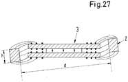
- the rotor comprises at least two impellers for mixing the substances, which are arranged at a distance from one another with respect to the axial direction. In particular, this ensures particularly good and homogeneous mixing of the substances even with larger mixing containers.
- At least two rotors arranged in the mixing container are provided, each of which comprises an impeller for mixing the substances, can be driven magnetically in a contactless manner and is each designed to be coil-free and preferably also free of permanent magnets, the rotors in the operating state with respect to the axial direction are spaced apart and coaxially arranged, and that the reusable device has two stators, each of which is designed as a bearing and drive stator, each stator each having an upper stator part with a plurality of pronounced upper poles for supporting upper windings and a lower stator part with a plurality of salient lower poles for supporting lower windings, the upper stator part and the lower stator part of each stator being arranged at a distance from one another with respect to the axial direction, wherein in each case between d A permanent magnet is provided in the upper stator part and the lower stator part, and the two stators are arranged at a distance from one another in the operating state with respect to the axial direction.
- This embodiment with at least two stators and at least two rotors enables, for example, operating states in which the two rotors rotate in opposite directions and / or at different speeds.
- Each rotor is assigned its own stator, which drives this rotor without contact and at the same time magnetically supports it without contact.
- the magnetically effective core of the rotor has a plurality of pronounced rotor poles which, in the operating state, face the poles of the stator. This makes it possible to ensure particularly good and efficient guidance of the magnetic flux.
- the rotor poles are designed or arranged asymmetrically in such a way that, in the operating state, locking positions with respect to the stator are avoided.
- This asymmetry is particularly suitable when the stator comprises a relatively small number of poles, for example three or four upper and four lower poles each.
- the symmetry between the rotor poles and the poles of the stator can be broken by the length of the rotor poles measured in the circumferential direction, or by the angular spacing of the rotor poles.
- This measure is intended to avoid such relative rotational positions between rotor and stator in which it is no longer possible, due to the symmetry, to exert a resultant torque on the rotor with the stator, in which the rotor engages when the rotor is at a standstill.
- a further advantageous measure consists in that the magnetically effective core of the rotor is designed in the shape of a ring, with a circumferential ring of constant diameter being formed in the center with respect to the axial direction and with the rotor poles being provided above and below the ring.
- a coil is arranged as a winding on each upper and each lower stator pole, with a separate power amplifier being provided for each coil, with which the coil current or the coil voltage for the coil can be regulated independently of the coil currents or the coil voltages of the other coils.
- This measure is particularly advantageous in order to exert a torque on the rotor with the stator as well as an arbitrarily adjustable transverse force in the radial direction, with which the radial position of the rotor - i.e. its position in the plane perpendicular to the target axis of rotation - can be actively magnetically regulated .
- the independent controllability of each coil also makes it possible for the position of the rotor to be actively magnetically regulated with regard to tilting relative to the target axis of rotation (two degrees of freedom) through the interaction of the upper and lower stator parts.
- a coil is arranged as a winding on each upper and on each lower stator pole, two coils being connected together to form an electrical phase, and a separate power amplifier being provided for each electrical phase. It is possible to connect two coils of the upper pole or two coils of the lower pole, as well as a coil of an upper pole with a coil of a lower pole. In the latter case, it is preferred if coils arranged one above the other are connected together. This interconnection of two coils to form an electrical phase enables the number of power amplifiers required to be reduced. In addition, in an embodiment with six upper and six lower poles in the stator, for example, conventional three-phase controllers can be used as power amplifiers.
- the permanent magnet of each stator is disk-shaped or ring-shaped, magnetized in the axial direction, and connects the upper stator part to the lower stator part, the permanent magnetically generated flux of course also through additional soft magnetic parts can be performed.
- the permanent magnet can also be made up of several individual magnets such as segment magnets or block magnets.
- the invention also proposes a disposable device according to claim 15, for a mixing device for mixing at least two substances, which comprises a reusable device which is designed for multiple use, the single use device being designed for single use, and a flexible mixing container for receiving the substances to be mixed, which is made of a plastic, and a rotor arranged in the mixing container, which includes an impeller for mixing the substances, and which is designed for a contactless magnetic drive, the disposable device for interaction with the reusable device is designed, and can be inserted into a support container of the reusable device, wherein the rotor can be driven by a stator of the reusable device in a contactless manner by a magnetic rotating field about a target axis of rotation, the rotor spu is designed free of len and free of permanent magnets.
- the rotor of the disposable device according to the invention can be produced particularly simply, economically and inexpensively by completely dispensing with permanent magnets, which is an enormous advantage for a disposable part. Also with regard to the dispatch of the disposable device, for example to the customer or after use to disposal companies, it is advantageous to dispense with permanent magnets because, depending on the material, they have to be specially declared in cross-border traffic, especially in air traffic, which causes additional effort and additional costs .
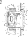
- Fig. 1 shows, in a perspective sectional illustration, a first exemplary embodiment of a mixing device according to the invention, which is designated as a whole with the reference number 1.
- Mixing devices 1 of this type can be used in particular in the pharmaceutical industry and in the biotechnological industry.
- the mixing device according to the invention is particularly suitable for those applications in which a very high degree of purity or sterility of those components which come into contact with the substances to be mixed is essential.
- the mixing device according to the invention can also be designed as a bioreactor or as a fermenter. It goes without saying, however, that the invention is not restricted to such configurations, but rather relates very generally to mixing devices with which media or substances are mixed. In particular, these substances can be fluids or solids, preferably powders.
- the mixing device 1 according to the invention is suitable for mixing liquids with one another and / or for mixing at least one liquid with a powder or other solid and / or for mixing gases with liquids and / or solids.
- the mixing device 1 comprises a single-use device, which is designated as a whole by the reference numeral 70 and is designed for single use, as well as a reusable device which is designated in its entirety by the reference numeral 50 and which is designed for permanent use, that is to say for multiple use.
- the disposable device 70 comprises those components which come into contact with the substances to be mixed during the mixing process.
- B. one-time part, one-time component, etc. those components or parts are meant that are designed for single use, that is, as intended, can only be used once and then disposed of. For a new application, a new, previously unused disposable part must then be used.
- the single-use device 70 it is therefore essential aspects that the single-use device 70 can be manufactured as simply and economically as possible, generate few costs and be manufactured from materials that are available as inexpensively as possible.
- the disposable device 70 can be joined together with the reusable device 50 to form the mixing device 1 in the simplest possible manner.
- the disposable device 70 should therefore be able to be replaced in a very simple manner, without the need for high assembly costs. It is particularly preferable for the disposable device 70 to be able to be assembled with the reusable device 50 without the use of tools.
- the disposable device 70 can be disposed of as simply as possible after its use. For this reason, preference is given to materials that have the lowest possible environmental impact, especially when they are disposed of.
- the disposable device 70 comprises a flexible mixing container 71 for receiving the substances to be mixed, which is made of a plastic.
- the mixing container 71 is preferably a flexible bag, for example a plastic or a plastic sack, which can be folded up so that it takes up as little space as possible during storage.
- the mixing container 71 has at least one inlet 72 through which the substances to be mixed can be introduced into the mixing container. Furthermore, at least one further inlet 73 is provided.
- the further inlet 73 or the further inlets 73 can be used, for example, for the supply of further substances, e.g. B. can be used during the mixing process.
- the further inlet 73 for receiving probes or measuring sensors with which parameters are monitored during the mixing process, e.g. B. temperature, pressure, concentrations, etc.
- the further inlet / inlets 73 can also be used for the exchange of substances, in particular during the mixing process.
- necessary gases can be supplied or removed.
- oxygen or air it is often necessary for oxygen or air to be supplied to the mixing container 71 and for other gases, in particular carbon dioxide, to be able to be discharged from the mixing container 71.
- At least one outlet 74 through which substances, for example the mixed substances, can be discharged, is also provided at the bottom of the mixing container 71.
- the outlet 74 arranged on the floor can, however, also be used to introduce a gas into the mixing container 71 which is intended to rise through the substances in the mixing container 71.
- the mixing container has in its bottom area a substantially cylindrical cup 75 which extends into the interior of the mixing container 71 and is arranged in the center of the bottom area.
- the cylindrical cup 75 is preferably dimensionally stable and made of a plastic. However, it can also be designed, for example, in the form of a flexible hose or bag made of plastic film.
- the disposable device 70 comprises a rotor 2 which is arranged in the mixing container 71 and which comprises an impeller 21 with a plurality of blades for mixing the substances. So that the rotor 2 can be magnetically driven in a contactless manner - that is, it can be set in rotation - it comprises a magnetically active core 22 (see also FIG Fig. 2 and Fig. 4 ), which is arranged radially on the inside with respect to the impeller 21.
- the rotor 2 has an essentially ring-shaped configuration with a central opening, so that in the position of use shown in FIG Fig. 1 is shown, is arranged around the cup 75, which is then located in the central opening of the rotor 2.
- the reusable device 50 comprises a dimensionally stable support container 51 for receiving the mixing container 71.
- the support container 51 has a plurality of feet 52 on its bottom 53, on which the support container 51 stands. Furthermore, at least one opening (in Fig. 1 not recognizable) is provided, which interacts in the assembled state with the outlet 74 of the mixing container 71 so that substances can be discharged from the mixing container 71 or introduced into it through the outlet 74 and a line 76 passing through the opening. Since the line 76 comes into contact with at least some of the substances, it is part of the disposable device 70 and, for example, is integrally formed on the bottom of the mixing container 71 or can be inserted into it.
- the essentially cylindrical support container 51 is open on its upper side, so that the mixing container 71 can be introduced into the support container 51 without any problems.
- the support container 51 has a centrally arranged, essentially cylindrical containment shell 4 for receiving a stator 3.
- the containment can 4 extends upwards in the direction of its cylinder axis, as shown, so that in the assembled state it is arranged coaxially in the cup 75 of the mixing container 71.
- the dimensions of the containment shell 4 and the can 75 are matched to one another in such a way that the can 75 tightly encloses the containment shell 4 in the assembled state and rests with its outer surface on the outer surface of the can 4.
- the stator 3 is arranged, which is designed as a bearing and drive stator, with which the rotor 2 can be driven in the operating state in a contactless manner about a target axis of rotation A and magnetically supported in a contactless manner with respect to the stator 3.
- the target axis of rotation A denotes that axis of rotation about which the rotor 2 rotates when it is in a centered position with respect to the stator 3 in the plane perpendicular to the cylinder axis of the containment can 4 and is not tilted with respect to this cylinder axis.
- the nominal axis of rotation A usually coincides with the cylinder axis of the containment can 4.
- the radial plane denotes that plane which is perpendicular to the nominal axis of rotation A and which is the magnetic center plane of the stator 3.
- the radial plane defines the x-y plane of a Cartesian coordinate system, the z-axis of which runs in the axial direction.
- the assembly of the disposable device 70 and the reusable device 50 to form the mixing device 1 is extremely simple and can be carried out quickly and, in particular, without tools.
- the mixing container 71 which is usually folded up for storage, with the rotor 2 located therein is removed from its packaging, placed in the support container 51 and the cup 75 with the rotor 2 lying around it is placed over the can 4.
- the mixing device 1 is then ready for use.
- the mixing container 71 with the cup 75 and the rotor 2 is simply pulled out of the support container 51.
- the cup 75 simply detaches itself from the containment shell 4.
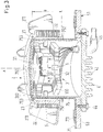
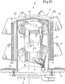
- Fig. 2 shows in one too Fig. 1 analog, but enlarged representation of the rotor 2 and the stator 3 of the first embodiment.
- the stator 3 is cast in the containment can 4 by means of a thermally conductive potting compound and is thus fixed in the containment can 4.
- the containment can 4 is closed at the bottom by a pot bottom 41, which has a plurality of cooling ribs 42.
- the pot bottom 41 comprises a radially outer flange 43 which is used to fasten the can 4 to the bottom 53 of the support container 51.
- the bottom 53 has a centrally arranged circular opening 531, which is dimensioned such that the containment can 4 can be pushed into the interior of the support container 51 from below through the opening 531, and then by means of screws 44 that reach through the flange 43, can be fixed on the bottom 53 of the support container 51.
- the pot bottom 41 has a bore through which a line 45 extends into the interior of the can 4.
- a line 45 extends into the interior of the can 4.
- All electrical connections are summarized, which are necessary for the energy supply and the control of the stator as well as for the data exchange between sensors and measuring devices with a control and regulating device, not shown. All of these electrical connections are provided with the reference numeral 46.
- the containment shell 4 can be made of a metallic material or a plastic.
- a variant of the fixed connection between the can 4 and the support container 51 consists in that the can 4 is only inserted into the cup 75 from below after the mixing container 71 has been inserted, as shown.
- This introduction can be done either by hand or by a lifting device which moves the can 4 through the opening 531 into the cup 75 and then holds it in this position.
- the containment can 4 does not need to be fixed separately on the support container 51. After use, the lifting device then moves the containment can 4 again as shown ( Fig. 2 ) downward.
- the cup 75 of the mixing container 71 is designed to be dimensionally stable in a preferred variant, but the rest of the mixing container 71, which is configured as a bag, is usually not, it is advantageous, but not absolutely necessary, to produce the cup 75 as a separate part and then to close it with the mixing container 71 connect.
- One possibility for this is in particular in Fig. 2 shown.
- the Dimensionally stable, essentially cylindrical cup is produced as a separate part with a flange 751 extending in the radial direction at its lower end as shown in the illustration, i.e. at the open end, for example with an injection molding process.
- the remainder of the mixing container 71 designed as a bag has a circular opening, the diameter of which is smaller than the diameter of the flange 751.
- the cup 75 is then inserted into the mixing container 71 so that the edge 711, which delimits the circular opening, is on the flange 751 of the cup 75 rests and overlaps with this.
- the cup 75 is then welded or glued to the mixing container in the area of the overlap between the flange 751 and the edge 711, so that the welded or glued seam connects the cup 75 firmly and permanently to the mixing container 71.
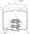
- Fig. 3 is still a preferred variant for the design of the cup 75 in a to Fig. 2 analog representation shown.
- a plurality of upper holding elements 753 and lower holding elements 752 are arranged on the outer jacket surface of the cup 75, distributed over the circumference of the cup 75.
- four upper and four lower holding elements 753 and 752 are provided.
- Each holding element 752, 753 is designed as a knob which extends away from the setpoint axis of rotation A in the radial direction.
- An upper holding element 753 and a lower holding element 752 are each arranged in pairs so that they are aligned with one another with respect to the axial direction and are spaced apart from one another by a distance B.
- the distance B is chosen so that the rotor 2 fits between the upper and lower holding elements 753 and 752 with a clear play in the axial direction.
- the length of the holding elements 752 and 753 in the radial direction is dimensioned such that the possibility of movement of the rotor 2 in the axial direction is restricted by the holding elements 753 and 752, respectively.
- the rotor 2 can therefore only move in the axial direction between the holding elements 753 and 752. This measure is particularly advantageous for storing the mixing container 75 before use and for inserting the mixing container 75 with the rotor 2 therein into the support container 51, because the rotor 2 is thus held approximately in the position it occupies during operation should.
- the holding elements 753, 752 have no function.
- the rotor 2 Since the rotor 2 is designed as a disposable part, it should be as simple and inexpensive as possible to manufacture.
- the structure of the rotor 2 is illustrated below with reference to FIG Fig. 2 or. Fig. 3 explained in more detail.
- the rotor 2 comprises the magnetically active core 22 and the impeller 21.
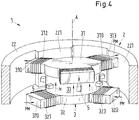
- FIG Fig. 4 A perspective sectional view of the magnetically active core 22 of the rotor 2 and of the stator 3 is also shown in FIG Fig. 5 a plan view of the stator 3 and the magnetically active core 22 of the rotor 2.
- the rotor 2 of the mixing device 1 is designed to be coil-free, i. H. no windings are provided on the rotor 2.
- the rotor 2 or the magnetically effective core 22 of the rotor 2 has no permanent magnets, so it is free of permanent magnets. This measure enables a particularly inexpensive design of the rotor 2 as a single-use part, because in particular no rare earths such as. B. neodymium or samarium, or compounds or alloys of these necessary, which are often used for the production of permanent magnets. Dispensing with these permanent magnets also means a great advantage from an environmental point of view.
- Permanent magnets are usually those ferromagnetic or ferrimagnetic materials that are hard magnetic, i.e. have a high coercive field strength.
- the coercive field strength is the magnetic field strength that is required to demagnetize a material.
- a permanent magnet is understood to mean a material which has a coercive field strength, more precisely a coercive field strength of the magnetic polarization, which is more than 10,000 A / m.
- the magnetically effective core 22 of the rotor only comprises materials whose coercive field strength is at most 10,000 A / m.
- the designation that the rotor 2 is “free of permanent magnets” should be understood in the context of this application to mean that the rotor 2 does not comprise any permanent magnets that make a significant contribution to the drive field for driving the rotation of the rotor 2. It is of course possible that other magnets or permanent magnets are provided on the rotor 2 which, for example, only serve to detect the angular position of the rotor or which otherwise serve a purpose that has nothing to do with generating the drive flux for the rotor. The term “free of permanent magnets” therefore only refers to the drive of the rotor 2.
- free of permanent magnets with respect to the rotor is to be understood in the context of this application so that the rotor 2 is free of permanent magnets that contribute to the drive of the rotor, or that the rotor 2 is free of permanent magnets that contribute to the drive flow for driving the rotor 2.
- the magnetically effective core 22 of the rotor is preferably made of a soft magnetic material, for example iron, nickel-iron or silicon-iron.
- the magnetically effective core 22 can be produced, for example, by casting, punching, pressing soft magnetic powder with subsequent sintering, forging, reshaping or assembling parts such as sheet metal.
- the magnetically effective core 22 is designed to be essentially ring-shaped (see in particular Fig. 4 ), wherein a plurality of salient rotor poles 221 are distributed over the inner circumference of the annular core and extend radially inward. With regard to the axial direction, each rotor pole 221 extends over the entire axial height of the annular magnetically active core 22.
- the magnetically active core 22 has four rotor poles 221 which are distributed equidistantly over the inner circumference of the annular magnetically active core ( please refer Fig. 5 ).
- the rotor 2 also has the impeller 21 with several blades 211 distributed over the circumference of the rotor 2, which blades can mix the substances in the mixing container 71.
- the impeller 21 is arranged radially outward with respect to the magnetically active core 22, the vanes 211 being arranged essentially at the same height with respect to the axial direction as the magnetically active core 22.
- the rotor 2 is designed as an integral rotor because it is both the rotor 2 of the electromagnetic drive and the magnetic bearing and the rotor 2 of the mixer. This offers the advantage of a very compact and space-saving design
- the magnetically effective core 22 has a sheath 23 (see Fig. 2 or. Fig. 3 ), which consists of a plastic and completely encloses the magnetically active core 22.
- the magnetically effective core is preferably cast in a plastic which forms the casing 23.
- the wings 211 can, for example, be placed on the casing 23 and there be fixed by means of a clamp connection, or glued or welded to the casing 23. It is also possible for the wings 211 to be an integral part of the casing 23.
- the parts made of plastic should be made of commercially available plastic that is as inexpensive as possible.
- the disposable device 70 or its components must be sterilizable for certain areas of application. It is particularly advantageous if the disposable device 70 can be gamma-sterilized. With this type of sterilization, the element to be sterilized is exposed to gamma radiation.
- the advantage of gamma sterilization for example in comparison to steam sterilization, is in particular that the sterilization can also take place through the packaging.
- single-use parts it is common practice that the parts are put into the packaging intended for shipping after they have been manufactured and then stored for a while before they are delivered to the customer. In such cases, the sterilization takes place shortly before delivery to the customer through the packaging, which is not possible with steam sterilization or other processes.
- the single-use device 70 offers the great advantage that the construction does not have to place emphasis on good cleanability of the single-use device 70, because the single-use device does not have to be cleaned when used as intended. Furthermore, it is generally not necessary for the disposable device 70 or its components to have to be sterilizable more than once. This is a great advantage, particularly in gamma sterilization, because exposure to gamma radiation can lead to degradation of plastics, so that multiple gamma sterilization can render the plastic unusable.
- plastics that can be gamma-sterilized at least once for the production of the disposable device.
- the materials should be gamma-stable for a dose of at least 40 kGy in order to enable a one-time gamma sterilization.
- the gamma sterilization should not produce any toxic substances.
- the following plastics are preferred for the production of the flexible mixing container 71: PolyEthylene (PE), Low Density PolyEthylene (LDPE), Ultra Low Density PolyEthylene (ULDPE), Ethylene Vinyl Acetate (EVA), PolyEthylene Terephthalate (PET), PolyVinyl Chloride (PVC) , PolyPropylene (PP), PolyUrethane (PU), Silicones
- PE PolyEthylene
- LDPE Low Density PolyEthylene
- ULDPE Ultra Low Density PolyEthylene
- EVA Ethylene Vinyl Acetate
- PET PolyEthylene Terephthalate
- PVC PolyVinyl Chloride
- PP PolyPropylene
- PU PolyUrethane
- the following plastics for example, are preferred: PolyEthylene (PE), PolyPropylene (PP), Low Density PolyEthylene (LDPE), Ultra Low Density PolyEthylene (ULDPE), Ethylene Vinyl Acetate (EVA), PolyEthylene Terephthalate (PET), PolyVinylChlorid (PVC), PolyVinyliDene Fluoride (PVDF), Acrylonitrile Butadiene Styrene (ABS), PolyAcryl, PolCarbonate (PC).
- PE PolyEthylene
- PP PolyPropylene
- LDPE Low Density PolyEthylene
- ULDPE Ultra Low Density PolyEthylene
- EVA Ethylene Vinyl Acetate
- PET PolyEthylene Terephthalate
- PVF PolyVinylChlorid
- PVDF PolyVinyliDene Fluoride
- ABS Acrylonitrile Butadiene Styrene
- Suitable or even unsuitable materials for the production of the plastic parts of the disposable device 70 are, for example, the materials known under the brand name Teflon, polytetrafluoroethylene (PTFE) and perfluoroalkoxy polymers (PFA).
- Teflon polytetrafluoroethylene
- PFA perfluoroalkoxy polymers
- the stator 3 is designed as a bearing and drive stator, with which the rotor 2 can be driven magnetically around the target axis of rotation A in a contactless manner in the operating state and can thus be set in rotation with respect to the stator 3 without contacting it magnetically.
- the stator 3 and the rotor 2 thus form an electromagnetic rotary drive which at the same time enables the rotor 2 to be supported magnetically.
- This electromagnetic rotary drive is particularly preferably designed according to the bearingless motor principle.
- bearingless motor means that the rotor 2 is supported completely magnetically, with no separate magnetic bearings being provided.
- the stator 3 is designed as a bearing and drive stator, so it is both the stator of the electric drive and the stator of the magnetic bearing.
- the stator comprises at least 3 windings with which a magnetic rotating field can be generated, which on the one hand exerts a torque on the rotor 2 that causes it to rotate, and on the other hand exerts an arbitrarily adjustable transverse force on the rotor 2, so that its radial position - that is, its position in the radial plane - can be actively controlled or regulated.
- at least three degrees of freedom of the rotor 2 can be actively regulated.
- the rotor 2 With regard to its axial deflection in the direction of the desired axis of rotation A, the rotor 2 is passively magnetic, that is to say it cannot be controlled, and is stabilized by reluctance forces. Also with regard to the remaining two degrees of freedom, namely tilting with respect to the radial plane perpendicular to the nominal axis of rotation A, the rotor 2 can likewise be passively magnetically stabilized, depending on the embodiment.
- the bearingless motor can be designed as an internal rotor, that is to say with an internal rotor and a stator arranged around it, or as an external rotor, that is to say with an internal stator 2 and a rotor 3 arranged around it.
- the electromagnetic rotary drive is designed as an external rotor.
- the stator 3 preferably comprises an upper stator part 31 with a plurality of salient upper poles 310 for supporting upper windings 311, 312, 313 and a lower stator part 32 with a plurality of salient lower poles 320 for supporting lower windings 321, 322, 323
- the upper stator part 31 and the lower stator part 32 are arranged at a distance from one another with respect to the axial direction.
- a permanent magnet 33 is provided between the upper stator part 31 and the lower stator part 32.
- the axial distance of the upper 31 from the lower stator part 32 and the thickness of the upper and lower stator parts 31, 32 are preferably dimensioned such that the total axial height of the stator 3 is at least approximately the same, and preferably the same, as the height of the magnetically effective core 22 of the rotor 2 in the axial direction.
- the stator 3 comprises exactly three upper poles 310 and exactly three lower poles 320.
- the upper and lower stator parts 31, 32 are essentially identical and each designed essentially disk-shaped, with each pole 310, 320 extending from the central one Disc part extends outward in the radial direction.
- the upper and lower stator parts 31, 32 are each made of a soft magnetic Material, for example iron, made and can also be designed as a stator core.
- the upper and lower stator parts 31, 32 are parallel to one another, with the permanent magnet 33 arranged between them, which is designed in the form of a disk or ring and connects the lower stator part 32 to the upper stator part 31.
- the permanent magnet 33 is magnetized in the axial direction - from bottom to top according to the illustration - as indicated by the arrows with the reference symbol M.
- the outer diameter of the permanent magnet 33 is dimensioned so that it is preferably not larger, and particularly preferably slightly smaller, than the diameter of the central disk part of the upper or lower stator part 31, 32
- the lower stator part 31, 32 is meant, which is left over when the poles 310 and 320 are imagined away.
- FIGS Fig. 1-5 The substantially identical upper and lower stator parts 31 and 32 are shown in FIGS Fig. 1-5
- the illustrated variant of the first exemplary embodiment is arranged rotated relative to one another by an angle ⁇ with respect to the nominal axis of rotation A (see Fig. 5 ), so that the upper poles 310, viewed in the axial direction, are each arranged in a gap between two adjacent lower poles 320.
- the angle ⁇ is 60 °, so that each upper pole 310, viewed in the axial direction, is arranged exactly in the middle between each two adjacent poles 320 of the lower stator part 32.
- This twisted arrangement of the upper 31 relative to the lower stator part 32 has the particular advantage that with a smaller number of upper and lower poles 310, 320, for example three or four lower and upper poles 310, 320 each, due to the interaction of the two stator parts 31, 32 for each relative angular position of the rotor 2 to the stator 3 with one of the two stator parts 31 or 32 a force can be generated on the rotor 2, while the other of the two stator parts 32 or 31 can be used to generate a torque on the rotor 2 , as will be explained further below.
- a coil 321, 322, 323, 311, 312, 313 is provided as a winding on each of the lower and upper poles 320, 310, with which a rotating electromagnetic field can be generated that exerts a torque on the rotor 2.
- an arbitrarily adjustable transverse force can be exerted on the rotor 2 with the coils 321, 322, 323, 311, 312, 313 according to the principle of the bearingless motor, with which the position of the rotor 2 in the radial plane can be actively magnetically regulated.
- position sensors 5 are provided with which the radial position of the rotor 2 - that is, its position in the radial or the x-y plane - can be determined.
- the position sensors 5 are preferably designed as Hall sensors or eddy current sensors and are signal-connected to a control and regulating device (not shown) via signal lines (not shown).
- a total of four position sensors 5 are provided, which are arranged on the inner wall of the containment can 4 approximately in the middle between the upper and lower stator parts 31, 32 and which are diametrically opposed in pairs.
- two position sensors 5 are sufficient to determine the position of the rotor 2 in the xy plane, namely one for each coordinate direction.
- a variant of the first exemplary embodiment is shown in which a different arrangement of the position sensors 5 is provided.
- more than four position sensors 5 are arranged in the stator 3, approximately in the middle between the upper and lower stator parts 31, 32, and preferably distributed equidistantly over the outer circumference of the permanent magnet 33.
- at least five position sensors 5 are necessary, a configuration with six or eight position sensors 5 being preferred.
- both the radial position of the rotor 22 and the angle of rotation of the rotor can be determined with the aid of the sensor signals.
- the position sensors 5 can be, for example, eddy current sensors, optical sensors, capacitive sensors or magnetic field sensors such as Hall sensors or GRM sensors.
- a small permanent magnet is preferably arranged behind the sensor if the stray field of the permanent magnet 33 should not be sufficient.
- the Fig. 4 and 5 the course of the permanent magnetic flux generated by the permanent magnet 5 is indicated schematically by the arrows provided with the reference symbol PM.
- the permanent magnetic flux runs in the axial direction as shown ( Fig. 4 ) up through the permanent magnet 33, is then guided radially outward in the upper stator part 31 through the upper poles 310 into the magnetically active core 22 of the rotor 2, runs there in the axial direction downwards as shown and is at the lower axial end of the magnetically active Core 22 guided radially inward into the lower poles 320 of the lower stator part 32, from where it is guided back in the axial direction into the permanent magnet.
- Fig. 5 the generation of a radially outwardly acting transverse force F 'on the rotor 2 is illustrated with an exemplary character for a rotational position of the rotor 2 relative to the stator 3.
- the oppositely equal force that acts on the stator 3 is denoted by F.
- the electromagnetic flux generated with the coils 311, 312, 313 arranged on the upper poles 310 is indicated by the dashed lines with the reference symbol EM.
- the permanent magnetic flux PM does not generate any resulting force on the rotor 2 due to the symmetrical application of force.
- the electromagnetic flux EM generated with the coils 311, 312, 313 emerges radially outward at the coils 312 and 313 in this snapshot the stator 3 and into the respective opposite rotor poles 221 in the rotor 2.
- the entire electromagnetic flux EM then exits the rotor pole 221 at the coil 311 and is guided radially inward into the upper pole 310, which carries the coil 311. In total, this results in the transverse force F acting radially outwards on the stator 3, which in FIG Fig. 5 is indicated by the arrow with the reference symbol F and a transverse force acting in the opposite direction on the rotor 2.
- This example shows how an arbitrarily adjustable transverse force on the rotor 2 can be generated with the stator 3, with which the radial position of the rotor 2 - that is, its position in the radial plane - is actively magnetically controllable. It can also be seen that the electromagnetic flux EM is always guided through soft magnetic material, except in the area of the air gaps between the rotor and stator, and does not lead through the permanent magnet 33.
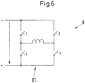
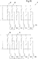
- an adjusting device for the control of the coils 311, 312, 313, 321, 322, 323 for generating the electromagnetic rotating field, there is an adjusting device, not shown, which has an amplifier unit 8 (see FIG Fig. 6 , Fig. 7 ) and is controlled by the control and regulation device.
- the configuration of the amplifier unit 8 two of which are described below, which are suitable for the first exemplary embodiment with a total of six coils 311, 312, 313, 321, 322, 323. It is advantageous if a separate power amplifier 81 is provided for each of the coils 311, 312, 313, 321, 322, 323, with which the coil current or the coil voltage for this coil can be regulated independently of the coil currents or the coil voltages of the other coils is.
- each of the coils 311, 312, 313, 321, 322, 323 is designed as precisely one discrete coil, which in itself forms an electrical phase.
- configurations are also possible in which some or each of the coils 311, 312, 313, 321, 322, 323 each comprise more than one discrete coil.
- the amplifier unit 8 comprises a total of six power amplifiers 81, namely one for each electrical phase.
- Each power amplifier 81 is a bipolar power amplifier 81, each of which is designed in a manner known per se as an H-bridge circuit. In Fig. 6 only one of these H-bridge circuits is shown because the circuit diagrams of the other five look identical.
- bipolar power amplifier means that both the phase currents and the phase voltages can each assume a positive and negative sign.
- the H-bridge circuits (see Fig. 6 ) are implemented in a manner known per se with switching transistors T and free-wheeling diodes (not shown) and are operated with the operating potentials + and -.
- the operating potential - is, for example, the earth potential.
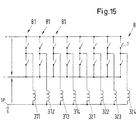
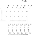
- Fig. 7 shows another variant for the power amplifier 81 of the amplifier unit 8 for separate regulation of the coil currents (or coil voltages) in the coils 311, 312, 313, 321, 322, 323.
- each of the six power amplifiers 81 is a bridge branch of the amplifier unit 8
- a bridge arm of the amplifier unit 8 is provided as a separate bipolar power amplifier 81 for each of the coils 311, 312, 313, 321, 322, 323 or for each of the separate electrical phases.
- Each bridge branch can, in a manner known per se, by means of switching transistors T and free-wheeling diodes (not shown), one of the coils 311, 312, 313, 321, 322, 323 with the respective coil current or the respective coil voltage.
- the amplifier unit 8 is operated with two operating potentials, which are shown in Fig. 7 are marked with + and -. These operating potentials +, - are direct voltage potentials. Between these two operating potentials lies the midpoint potential O, which is, for example, the earth potential.
- Each coil 311, 312, 313, 321, 322, 323 is connected on the one hand to the bipolar power amplifier 81 supplying it. On the other hand, each coil 311, 312, 313, 321, 322, 323 is connected to a common star point SP which is at the midpoint potential O.
- the star point SP is designed as a loadable star point SP, that is, it is connected to a loadable potential, so that, apart from the six coil currents, an additional current can flow away via the star point SP or into it.
- each coil current can be regulated completely independently of the other coil currents.
- Fig. 8 shows a perspective sectional view of the stator 3 and the magnetically active core 22 of the rotor 2 a first variant of the first embodiment with an alternative configuration of the magnetically active core 22 of the rotor 2.
- This variant of the magnetically active core 22 of the rotor 2 is also in this variant essentially ring-shaped, but a circumferential ring 222 is provided in the center (in relation to the axial direction), which ring has an inner diameter that is constant over the entire circumference.
- the rotor poles - here four - are then provided above and below the ring 222.
- This refinement makes it possible to increase the number of position sensors 5 compared to that in FIG Fig. 4 to reduce the variant shown.
- Fig. 8 Three further sensors 6, which are used to determine the current rotational position of the rotor 2 in each case. They can be used to determine the current angle of rotation (measured against an arbitrarily definable zero angle) of the rotor 2 relative to the stator 3. This angle of rotation is generally required for regulating the electromagnetic rotary drive in a configuration based on the bearingless motor principle.
- the three sensors 6 are arranged, for example, on an electronics print 61 arranged below the stator as shown in the illustration. All three sensors 6, viewed in the axial direction, are arranged in the same gap between two adjacent lower poles 320 of the lower stator part 32 and are all the same distance from the target axis of rotation A.
- the sensors 6 are preferably designed as Hall sensors or as eddy current sensors, with one metallic design of the can 4 Hall sensors are preferred. Depending on the configuration, the stray magnetic field at the location of the sensors 6 is sufficient to determine the current value of the angle of rotation of the rotor 2. If this stray field is not sufficient, each of the Hall sensors 6 can each be equipped with a small permanent magnet (not shown), which is glued onto the respective sensor 6, for example.
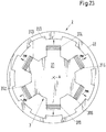
- Fig. 9 shows a plan view of the stator 3 and the magnetically active core 22 of the rotor 2 from the direction of the target axis of rotation A for a second variant of the first embodiment with an alternative configuration of the magnetically active core 22 of the rotor 2.
- the magnetically active core 22 of the rotor 2 has a total of eight rotor poles 221, which are equidistant across the inner circumference of the magnetically effective core 22 of the rotor 2 are distributed and all of which have the same length measured in the circumferential direction.
- the magnetically effective core 22 of the rotor can have the in Fig. 8 encircling ring 222 shown.
- Increasing the number of rotor poles 221 to a number which does not correspond to a multiple of the number of poles 310 or 320 of stator 3 has the advantage that, in particular in those embodiments of the electromagnetic rotary drive that have a single-phase characteristic, the number of possible Latching positions in which no resulting torque can be exerted by the stator 3 on the rotor 2 can be significantly reduced or even brought to zero.
- the problem of the locking or locking positions (or locking moments) is known in particular from the technology of single-phase motors. There are certain relative angular positions between stator 3 and rotor 2 in which no resultant torque can be produced on rotor 2 with stator 3. If such an angular position coincides with a detent position, that is to say a position in which the cogging torque has a maximum, the motor can no longer start up independently.
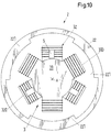
- Fig. 10 shows in one too Fig. 9 analogous representation of a top view of the stator 3 and the magnetically active core 22 of the rotor 2 from the direction of the target axis of rotation A for a third variant of the first embodiment with an alternative configuration of the magnetically active core 22 of the rotor 2.
- the magnetically active core 22 of the rotor 2 have a total of three rotor poles 221 which are distributed equidistantly over the inner circumference of the magnetically active core 22 of the rotor 2 and which all have the same length measured in the circumferential direction.
- the magnetically effective core 22 of the rotor can have the in Fig. 8 encircling ring 222 shown.
- the rotor poles 221 are designed or arranged at least slightly asymmetrically. There are many ways to achieve this asymmetry, only a few of which are mentioned here as examples. For example, it is possible not to distribute the rotor poles 211 exactly equidistantly over the circumference of the magnetically active core 22, or the lateral delimiting edges of the rotor poles 211 can be configured asymmetrically, for example with different bevels. It is also possible for the individual rotor poles 211 to have at least slightly different lengths - measured in the circumferential direction. Furthermore, the extent of a rotor pole 211 in the radial direction can vary over its length as seen in the circumferential direction.
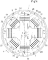
- Fig. 11 shows in one too Fig. 9 analogous representation, a plan view of the stator 3 and the magnetically active core 22 of the rotor 2 from the direction of the target axis of rotation A for a fourth variant of the first embodiment with an alternative configuration of the magnetically active core 22 of the rotor 2.
- the magnetically active core 22 of the rotor 2 have a total of twelve rotor poles 221, which are distributed equidistantly over the inner circumference of the magnetically active core 22 of the rotor 2 and which all have the same length measured in the circumferential direction.
- the magnetically effective core 22 of the rotor can have the in Fig. 8 encircling ring 222 shown.
- the comparatively high number of twelve rotor poles 221 is particularly advantageous with regard to the radial force control, since the influence of the rotor angle on the radial force amplitude decreases with an increasing number of poles.
- the symmetry of the arrangement is also advantageous with regard to the radial force control.
- the number of rotor poles 221 corresponds to a multiple of the number of the upper 310 or lower poles 320 of the stator 3 and the rotary drive according to the embodiment in FIG Fig. 11 Has single-phase characteristics, the locking positions also coincide here with rotor angles at which no torque can be achieved. Additional measures are also provided here so that the rotary drive can start up. In addition to those already related to Fig. 10 The measures discussed below are also based on Fig. 12 measure described on the embodiment of Fig. 11 applicable..
- Fig. 12 shows a plan view of the stator 3 and the magnetically active core 22 of the rotor 2 from the direction of the target axis of rotation A for a first variant of the first embodiment with an alternative design of the stator 3.
- the essentially identical upper and lower stator parts 31 and 32 are also arranged rotated relative to one another by an angle ⁇ with respect to the setpoint axis of rotation A, so that the upper poles 310, viewed in the axial direction, are each arranged between two adjacent lower poles 320.
- the angle ⁇ in the case of in Fig.
- Fig. 13 shows a perspective view of a second variant for the design of the stator 3 of the first embodiment.
- the upper stator part 31 has exactly four upper poles 310, each of which carries an upper coil 311, 312, 313, 314 as a winding.
- the lower stator part 32 has exactly four lower poles 320, each of which carries a lower coil 321, 322, 323, 324 as a winding.
- the number of upper poles 310 is equal to the number of lower poles 320, but here the number of upper poles 310 and the number of lower poles 320 are each an even number, namely four.
- Both the upper poles 310 and the lower poles 320 are each arranged equidistantly with respect to the circumferential direction, that is, the angle between adjacent poles 310, 320 is 90 ° in both the upper stator part 31 and the lower stator part 32.
- FIGS Fig. 13 The essentially identically configured upper and lower stator parts 31 and 32 are shown in FIGS Fig. 13
- Fig. 14 shows a plan view of the stator 3 from Fig. 13 together with the magnetically active core 22 of the rotor 2, which here has six rotor poles 221. Based on Fig. 14 the interaction of the two stator parts 31, 32 for generating force and torque on the rotor 2 is to be explained. Since the permanent magnetic flux can be ignored for this purpose, only the electromagnetic flux will be discussed below.
- Fig. 14 shows a snapshot of the rotational position of the magnetically active core 22 of the rotor 2 relative to the stator 3.
- the course of the electromagnetic flux on the plane of the lower stator part 32 is indicated by the dotted lines with the reference symbol EM '
- the course of the electromagnetic flux on the plane of the upper stator part 31 is indicated by the dashed lines with the reference symbol EM.
- the upper stator part 31 generates a resultant force on the stator 3, which is indicated by the arrow F and is directed radially outward as a transverse force and accordingly an equally large oppositely directed force F 'on the rotor 2. At this level, however, no resulting torque is exerted on the rotor.
- the actuating device for controlling the stator 3 comprises an amplifier unit 8, which has a separate power amplifier 81 for each of the eight coils 311, 312, 313, 314, 321, 322, 323, 324, with which the coil current for each of the coils is independent can be regulated by the coil currents of the respective other coils.
- each separate power amplifier can be used as an H-bridge circuit according to FIG Fig. 6 is designed, with eight H-bridges then being provided as power amplifiers 81 for the variant described here.
- each power amplifier 81 can also be designed as a bridge branch of an amplifier unit 8, in the same way as this in connection with FIG Fig 7 was explained.
- the corresponding circuit is in Fig. 15 shown.
- the star point SP is preferably, but not necessarily, designed as a loadable star point.
- the opposing coils are preferably connected together in pairs in each of the upper and lower stator parts 31, 32. Because of the symmetry, the coil currents in the two coils forming a pair are then conversely the same.
- the following pairs of coils are each interconnected to form an electrical phase:
- the coil 321 is interconnected with the coil 323 and the coil 322 with the coil 324.
- the coil 311 is interconnected with the coil 313 and coil 312 with coil 314.
- FIG. 16 The corresponding circuit diagram with the separate power amplifiers 81 for each electrical phase is shown in FIG Fig. 16 for the variant with H-bridge circuits for the separate power amplifier 81 and in Fig. 17 for the variant with bridge branches.
- FIG. 17 the star point SP can be loaded.
- Fig. 18 shows in a perspective view a third variant for the design of the stator 3 of the first embodiment. Shows for a better understanding Fig. 19 Another plan view from the axial direction of the stator 3 Fig. 18 together with the magnetically active core 22 of the rotor 2.
- the upper stator part 31 has exactly six upper poles 310, each of which has an upper coil 311, 312, 313, 314, 315, 316 as a winding.
- the lower stator part 32 has exactly six lower poles 320, each of which carries a lower coil 321, 322, 323, 324, 325, 326 as a winding.
- the number of upper poles 310 is equal to the number of lower poles 320, the number of upper poles 310 and the number of lower poles 320 each being an even number, namely six.
- Both the upper poles 310 and the lower poles 320 are each arranged equidistantly with respect to the circumferential direction, that is, the angle between adjacent poles 310, 320 is 60 ° in both the upper stator part 31 and the lower stator part 32.
- FIGS Fig. 18 and Fig. 19 The essentially identically configured upper and lower stator parts 31 and 32 are shown in FIGS Fig. 18 and Fig. 19
- the actuating device for controlling the stator 3 comprises an amplifier unit 8 which has a separate power amplifier 81 for each of the twelve coils 311, 312, 313, 314, 315, 316, 321, 322, 323, 324, 325, 326, with which the coil current for each of the coils can be regulated independently of the coil currents of the respective other coils.
- each separate power amplifier is designed, with twelve H-bridges then being provided as power amplifiers 81 for the variant described here.
- each power amplifier 81 can also be designed as a bridge branch of an amplifier unit 8, in the same way as this in connection with FIG Fig 7 was explained.
- the corresponding circuit is in Fig. 20 shown.
- the star point SP is preferably, but not necessarily, designed as a loadable star point.
- the opposing coils are preferably connected together in pairs in each of the upper and lower stator parts 31, 32.
- the following pairs of coils are each interconnected to form an electrical phase:
- the coil 321 is interconnected with the coil 324
- the coil 322 with the coil 325 and the coil 323 with the coil 326 coil 311 is interconnected with coil 314, coil 312 with coil 315, and coil 313 with coil 316.
- FIG Fig. 21 The corresponding circuit diagram with the separate power amplifiers 81 for each electrical phase is in FIG Fig. 21 shown for the variant with bridge branches. At the in Fig. 21 It is advantageous, but not necessary, that the star point SP can be loaded.
- Fig. 22 shows a fourth variant for the design of the stator 3 of the first embodiment in a perspective view. Shows for a better understanding Fig. 23 Another plan view from the axial direction of the stator 3 Fig. 22 together with the magnetically active core 22 of the rotor 2.
- the upper stator part 31 has exactly six upper poles 310, each of which carries an upper coil 311, 312, 313, 314, 315, 316 as a winding.
- the lower stator part 32 has exactly six lower poles 320, each of which carries a lower coil 321, 322, 323, 324, 325, 326 as a winding.
- the number of upper poles 310 is equal to the number of lower poles 320, the number of upper poles 310 and the number of lower poles 320 each being an even number, namely six.
- Both the upper poles 310 and the lower poles 320 are each arranged equidistantly with respect to the circumferential direction, that is, the angle between adjacent poles 310, 320 is 60 ° in both the upper stator part 31 and the lower stator part 32.
- FIGS Fig. 22 and Fig. 23 The essentially identically configured upper and lower stator parts 31 and 32 are shown in FIGS Fig. 22 and Fig. 23
- the variant shown is not rotated relative to one another with respect to the nominal axis of rotation A, that is to say the angle ⁇ is equal to 0 °. Consequently, the upper poles 310 and the lower poles 320 are arranged so that they overlap when viewed in the axial direction.
- FIG Fig. 21 The corresponding circuit diagram with the separate power amplifiers 81 for each electrical phase is shown in FIG Fig. 21 shown for the variant with bridge branches. At the in Fig. 21 It is advantageous, but not necessary, that the star point SP can be loaded.
- Fig. 25 shows in one too Fig. 2 analogous representation, a perspective sectional representation of a second exemplary embodiment of a mixing device 1 according to the invention. In the following, only the differences from the first exemplary embodiment described above will be discussed.
- the rotor 2 has two impellers 21, 25 for mixing the substances, which are arranged at a distance from one another with respect to the axial direction. Both impellers 21 and 25 are part of the single rotor 3 and are each provided radially outward on the magnetically active core 22 of the rotor.
- the stator 3 in the second exemplary embodiment has a greater height in the axial direction. This can be achieved, for example, by increasing the extent of the permanent magnet 33 of the stator 3 in the axial direction, so that the distance between the lower stator part 32 and the upper stator part is also increased, or by the axial height of the lower and / or or the upper stator part 32, 31 is enlarged, or by a combination of these two measures.
- the rotor 2 and the stator 3 are preferably designed in such a way that, in the operating state, one impeller 21 is arranged at the same height (in the axial direction) as the lower stator part 32 and the other impeller 25 is arranged at the same height as the upper stator part 32.
- the magnetically effective core 22 of the rotor 2 is also here preferably designed in an essentially ring-shaped or cylindrical shape and extends essentially over the entire axial height of the rotor 2.
- position sensors 5 are provided both in the area of the lower stator part 32 and in the area of the upper stator part 31, so that tilting of the rotor 3 with respect to the radial plane can be detected.
- each of the coils of the lower stator part 32 and each of the coils of the upper stator part 31 can be controlled separately so that the rotor 3 can be actively magnetically regulated with respect to tilting relative to the radial plane (two degrees of freedom).
- the two stator parts 31, 32 can also have more than three coils and poles, in particular also four, five or six, 5 and 6 coils and upper poles 310 and lower poles 320.
- Fig. 26 shows in one too Fig. 1 analogous illustration shows a perspective sectional illustration of a third exemplary embodiment of a mixing device 1 according to the invention.
- Fig. 1 analogous illustration shows a perspective sectional illustration of a third exemplary embodiment of a mixing device 1 according to the invention.
- the reference symbols have the same meaning as they have already been explained in connection with the first and second exemplary embodiments. It goes without saying that all the variants, embodiments and measures described above can also be implemented in the same way or in an analogous manner in the third embodiment.
- the third exemplary embodiment is characterized in that two rotors 2, 2 'are provided in the mixing container, each of which comprises an impeller 21, 21' for mixing the substances.
- each rotor 2, 2 ' can be driven magnetically in a contactless manner and is designed to be coil-free.
- the two rotors 2, 2 'are spaced apart with respect to the axial direction and are arranged coaxially, ie they have the same nominal axis of rotation A.
- stators 3, 3 'are provided, each of which is designed according to one of the configurations described above. Both stators 3, 3 'are arranged in the containment shell 4 and axially spaced from one another.
- the lower stator 3 according to the illustration is assigned to the lower rotor 2 according to the illustration and together with it forms an electromagnetic rotary drive which is designed according to the bearingless motor principle.
- the upper stator 3 'according to the illustration is assigned to the lower rotor 2' according to the illustration and together with it forms an electromagnetic rotary drive which is designed according to the principle of the bearingless motor.
- the two rotors 2, 2 ' are also designed according to one of the configurations described above.
- the two rotors 2, 2 ' can be designed essentially the same or different.
- stators 3, 3 ' can also be configured essentially the same or differently, for example with a different number of lower or upper poles 320, 310.
- the particular advantage of the third exemplary embodiment is that significantly more mixing processes can be implemented with this, for example it is possible for the two rotors 2, 2 'to rotate in different directions and / or at different rotational speeds.
- the stator 3 and the rotor 2 together form an electromagnetic rotary drive which, as already explained, preferably works on the principle of the bearingless motor.
- a bearingless motor at least three straight lines of freedom of the rotor, namely its rotation about the target axis of rotation A and its position in the radial plane, are actively magnetically controllable.
- the degree of freedom of the axial position of the rotor 3 is passively magnetically stabilized in the bearingless motor of the mixing device according to the invention, that is to say no separate axial magnetic bearing or mechanical axial bearing is necessary.
- the rotor 2 which is part of the disposable device 70 of the mixing device 1, is particularly simple and inexpensive and, on the other hand, the rotor 2, together with the other components of the disposable device 70, can be easily separated from the reusable device 50, in particular from the stator 3 and from the Can 4. Due to the lack of axial bearing components, the rotor 2, which is limited in its freedom of movement with respect to the axial direction at most only via the holding elements 752, 753 connected to the cup 75, together with the cup 75 can simply be axially removed from the can 4, which the stator 3 contains, are drawn.
- the magnetically effective core 22 of the rotor 2 is withdrawn when it is deflected in the axial direction by the magnetic fields emanating from the stator, as if by magnetic spring forces. This is shown in the very schematic representation in Fig. 28 illustrated. If the rotor 3 is moved out of the nominal position with respect to its axial position, i.e. out of the radial plane (in Fig. 28 downwards according to the illustration), this causes passive magnetic axial restoring forces, represented by the arrows FA in the axial direction, which move the rotor 2 back into its desired position with respect to the axial direction after the other external forces have disappeared.
- the forces FA initially increase with the deflection, reaching a certain deflection, which depends on the geometry of the magnetically active core 22 of the rotor 2, the geometry of the upper stator part 31 and the lower stator part 32, the distance between the upper stator part 31 and the lower stator part 32, the geometry and the magnetic properties of the permanent magnet 33 and the air gap (the distance between the stator parts 31 and 32 on the one hand and the magnetically active core 22 of the rotor 2 on the other hand) depend, a maximum and then decrease again.
- the characteristic of the inherent axial passive magnetic bearing is chosen so that the axial forces which act on the rotor 2 are below the maximum force of the axial passive magnetic bearing in the entire operating range, and that the maximum force of the axial passive magnetic bearing is small enough What remains is that the rotor 2 with the disposable device 70 can be separated from the can 4 and the stator 3 easily and without tools.
- a maximum force of the axial passive magnetic bearing of a maximum of 200 Newtons has proven to be manageable without tools or auxiliary devices.
- a significantly smaller maximum force of the axial passive magnetic bearing is selected in order to make the insertion and removal of the disposable device 70 from the reusable device 50 as simple as possible.
- the vane inclination can also take place in opposite directions, for example in the direction of rotation of the lower vane wheel of the rotor 2 according to the illustration and reverse to the direction of rotation of the upper vane wheel of the rotor 2 'according to the illustration, so that the hydrodynamic axial forces cancel each other out completely or partially.
- the rigidity of the axial passive magnetic bearing is important for the optimal function of the mixing device according to the invention in addition to the maximum force.
- the rigidity of the axial passive magnetic bearing should be selected so that operating states are avoided in which the rotor 2 touches the holding elements 752, 753 or other parts of the mixing device.
- the position sensors 5 can determine the radial position and possibly also the angular position of the rotor 2 in every operating state.
- the in Fig. 8 It must be ensured that in each operating state, the axial deflection of the rotor 2 is limited to such an extent that a sufficient axial overlap between the circumferential ring 222 and the position sensors 5 is still ensured.
- passive magnetic stabilization can also be implemented.
- the control of the bearingless motor is particularly simple and the number of power amplifier channels can also be reduced.
- FIG Fig. 27 How this can be achieved in the case of the bearingless motor of the mixing device according to the invention is shown in FIG Fig. 27 made clear.
- the tilting of the rotor 2 shown there results in passive magnetic restoring forces which, due to their different direction, cause a torque on the left and right side of the rotor 2 according to the illustration, which counteracts the tilting, so that the rotor 2 is also passively magnetic with regard to these two degrees of freedom is stabilized.
- This passive stabilization only works if certain geometric conditions are met. If d denotes the inside diameter of the rotor 2 and h denotes the height of the magnetically active core 22 of the rotor, then the inside diameter must be at least 2.6 times as large as the height h. The condition d> 2.6 * h should therefore be fulfilled, that is, the inside diameter d should be greater than 2.6 times the height h.
- the mixing device 1 it is also preferred for the mixing device 1 according to the invention if the rotor 2 is purely passively magnetically stabilized with respect to tilting to the radial plane (two degrees of freedom) if the inner diameter of the rotor 2 is at least 2.6 times as large as the height h of the magnetic effective core 22 in the axial direction.
- the rotor 2 is actively magnetically regulated with respect to these tilts.
- such a configuration as an internal runner can be implemented, for example, in such a way that the cup 75 is not oriented into the mixing container 71, but out of the mixing container 71, as shown in FIG Fig. 1 or Fig. 2 downward.
- the rotor 2 is then placed in the interior of the can 75 and the stator 3 is placed around the can 75.
- a disposable device 70 for a mixing device 1 for mixing at least two substances is also proposed, the mixing device 1 comprising a reusable device 50 which is designed for multiple use.
- the disposable device 70 is designed for single use and comprises a flexible mixing container 71 for receiving the substances to be mixed, which is made of a plastic, as well as a rotor 2 arranged in the mixing container 71, which includes an impeller 21 for mixing the substances, and which is designed for a contactless magnetic drive, wherein the disposable device 70 is designed to interact with the reusable device 50, and can be inserted into a support container 51 of the reusable device 50, the rotor 2 through a stator 3 of the reusable device 50 without contact a rotating magnetic field can be driven around a target axis of rotation A.
- the rotor 2 is designed to be coil-free and free of permanent magnets.
- the disposable device 70 according to the invention is particularly suitable for the mixing device 1 according to the invention, which is described above.
- the disposable device according to the invention is not limited to the specifically described mixing device 1 or to the specifically described configuration of the reusable device 50 of the mixing device 1.
- the single-use device is also suitable for interaction with differently designed mixing devices, for example those in which the reusable part of the mixing device comprises a stator which is designed without permanent magnets, i.e. in which the drive of the rotor 2 takes place electromagnetically, or the generation of the Drive flow is based only on electromagnetically generated rotating fields.
Landscapes
- Engineering & Computer Science (AREA)
- Power Engineering (AREA)
- Chemical & Material Sciences (AREA)
- Chemical Kinetics & Catalysis (AREA)
- Physics & Mathematics (AREA)
- Thermal Sciences (AREA)
- Microelectronics & Electronic Packaging (AREA)
- General Engineering & Computer Science (AREA)
- Mechanical Engineering (AREA)
- Mixers With Rotating Receptacles And Mixers With Vibration Mechanisms (AREA)
Description
Die Erfindung betrifft eine Mischvorrichtung zum Mischen von mindestens zwei Substanzen sowie eine Einmalvorrichtung für eine Mischvorrichtung gemäss dem Oberbegriff des unabhängigen Patentanspruchs der jeweiligen Kategorie.The invention relates to a mixing device for mixing at least two substances and a disposable device for a mixing device according to the preamble of the independent claim of the respective category.
Mischvorrichtungen zum Mischen von mindestens zwei Substanzen, beispielsweise von zwei Flüssigkeiten oder von einer Flüssigkeit mit einem Pulver oder von Flüssigkeiten oder Suspensionen mit Gasen werden in vielen technischen Gebieten eingesetzt. Bei vielen Anwendungen kommt dabei der Reinheit des Mischbehälters, in welchem die Vermischung stattfindet, sowie der darin befindlichen Komponenten eine sehr grosse Bedeutung zu. Als Beispiele seien hier die Pharmaindustrie und die biotechnologische Industrie genannt. Hier werden häufig Lösungen und Suspensionen hergestellt, die eine sorgfältige Durchmischung der Substanzen verlangen.Mixing devices for mixing at least two substances, for example two liquids or one liquid with a powder, or liquids or suspensions with gases, are used in many technical fields. In many applications, the purity of the mixing container in which the mixing takes place and the components contained therein are of great importance. Examples are the pharmaceutical industry and the biotechnological industry. Solutions and suspensions are often produced here that require thorough mixing of the substances.
In der Pharmaindustrie müssen beispielsweise bei der Herstellung von pharmazeutisch wirksamen Substanzen höchste Ansprüche an die Reinheit gestellt werden, oft müssen die mit den Substanzen in Kontakt kommenden Komponenten sogar steril sein. Ähnliche Anforderungen ergeben sich auch in der Biotechnologie, beispielsweise bei der Herstellung, Behandlung oder Züchtung von biologischen Substanzen, Zellen oder Mikroorganismen, wo ein extrem hohes Mass an Reinheit gewährleistet sein muss, um die Brauchbarkeit des hergestellten Produkts nicht zu gefährden. Als ein weiteres Beispiel seien hier Bioreaktoren genannt, in denen beispielsweise biologische Substitute für Gewebe oder spezielle Zellen oder andere sehr empfindliche Substanzen gezüchtet werden. Auch hier benötigt man Mischvorrichtungen, um beispielsweise eine kontinuierliche Durchmischung der Nährflüssigkeit beziehungsweise deren kontinuierliche Zirkulation im Mischbehälter zu gewährleisten. Dabei muss eine sehr hohe Reinheit gewährleistet sein, um die Substanzen oder die erzeugten Produkte vor Kontaminationen zu schützen.In the pharmaceutical industry, for example, the production of pharmaceutically active substances must meet the highest purity requirements, and the components that come into contact with the substances often have to be sterile. Similar requirements also arise in biotechnology, for example in the production, treatment or cultivation of biological substances, cells or microorganisms, where an extremely high degree of purity must be guaranteed in order not to endanger the usability of the manufactured product. Another example is bioreactors, in which, for example, biological substitutes for tissue or special cells or other very sensitive substances are cultivated. Mixing devices are also required here in order, for example, to ensure continuous mixing of the nutrient liquid or its continuous circulation in the mixing container. A very high level of purity must be guaranteed in order to protect the substances or the products produced from contamination.
Um die Reinheitserfordernisse für den Prozess möglichst gut erfüllen zu können, ist man bemüht, die Anzahl der mit den jeweiligen Substanzen in Kontakt kommenden Komponenten einer Mischvorrichtung möglichst klein zu halten. Hierzu sind elektromagnetisch betriebene Mischvorrichtungen bekannt, bei denen ein Rotor, der üblicherweise ein Flügelrad umfasst, in dem Mischbehälter angeordnet ist. Ausserhalb des Mischbehälters ist dann ein Stator vorgesehen, welcher mittels magnetischer bzw. elektromagnetischer Felder den Rotor durch die Wand des Mischbehälters berührungslos antreibt und berührungslos magnetisch in einer Sollposition lagert. Dieses "berührungslose" Konzept hat insbesondere auch den Vorteil, dass keine mechanischen Lager oder Durchführungen in den Mischbehälter benötigt werden, die eine Ursache von Verunreinigungen bzw. Kontaminationen bilden können.In order to be able to meet the purity requirements for the process as well as possible, efforts are made to keep the number of components of a mixing device that come into contact with the respective substances as small as possible. For this purpose, electromagnetically operated mixing devices are known in which a rotor, which usually comprises an impeller, is arranged in the mixing container. Outside the mixing container, a stator is then provided which, by means of magnetic or electromagnetic fields, drives the rotor through the wall of the mixing container in a contactless manner and magnetically supports it in a target position without contact. This “contactless” concept also has the particular advantage that no mechanical bearings or feedthroughs are required in the mixing container, which could be a cause of soiling or contamination.
Eine besonders effiziente derartige Vorrichtung, mit welcher Substanzen in einem Bioreaktor zirkuliert bzw. durchmischt werden, wird im Rahmen der
Der Rotor dieser Mischvorrichtung stellt einen Integralrotor dar, weil er sowohl der Rotor des elektromagnetischen Antriebs ist, als auch der Rotor des Mischers. Neben der berührungslosen magnetischen Lagerung bietet der lagerlose Motor ferner den Vorteil einer sehr kompakten und platzsparenden Ausgestaltung.The rotor of this mixing device is an integral rotor because it is both the rotor of the electromagnetic drive and the rotor of the mixer. In addition to the contactless magnetic bearing, the bearingless motor also offers the advantage of a very compact and space-saving design.
Obwohl sich mit solchen berührungslos magnetisch gelagerten Mischern die Anzahl der mit den Substanzen in Kontakt kommenden Komponenten stark reduzieren lässt, ist die Reinigung bzw. das Sterilisieren dieser Komponenten immer noch mit einem sehr grossen Zeit- Material- und Kostenaufwand verbunden. Daher geht man häufig dazu über - wie dies auch in der bereits zitierten
Bei der Ausgestaltung als Einmalteil ist der Mischbehälter häufig als flexibler Kunststoffbeutel mit darin enthaltenem Rotor ausgestaltet. Diese Beutel werden oft schon bei der Herstellung oder aber nach dem Verpacken und dem Lagern sterilisiert und dem Kunden in steriler Form in der Verpackung zugestellt.When designed as a disposable part, the mixing container is often designed as a flexible plastic bag with a rotor contained therein. These bags are often sterilized during manufacture or after packaging and storage and are delivered to the customer in sterile form in the packaging.
Bei der Herstellung bzw. der Konzipierung von Einmalteilen für den Einmalgebrauch ist es ein wichtiges Kriterium, dass sie in möglichst einfacher Weise mit der wiederverwendbaren Vorrichtung bzw. deren Komponenten zusammengesetzt werden können. Es ist wünschenswert, dass dieses Zusammensetzen mit möglichst geringem Aufwand, mit wenigen Handgriffen, rasch und vorzugsweise ohne Werkzeug erfolgen kann.In the manufacture or the design of disposable parts for single use, it is an important criterion that they can be assembled with the reusable device or its components in the simplest possible way. It is desirable that this assembly can be carried out quickly and preferably without tools with as little effort as possible, in a few simple steps.
Ein anderer Aspekt ist es, dass diese Einmalteile möglichst wirtschaftlich und kostengünstig gefertigt werden können. Hierbei wird insbesondere auch Wert auf preisgünstige, einfache Ausgangsmaterialien, wie beispielsweise handelsübliche Kunststoffe, gelegt. Auch ein umweltbewusster Umgang sowie eine verantwortungsvolle Nutzung der zur Verfügung stehenden Resourcen sind wesentliche Aspekte bei der Konzeption von Einwegteilen.Another aspect is that these single-use parts can be manufactured as economically and inexpensively as possible. In particular, value is placed on inexpensive, simple starting materials, such as commercially available plastics. Environmentally conscious handling and responsible use of the available resources are also essential aspects when designing single-use parts.
Ausgehend von diesem Stand der Technik ist es eine Aufgabe der Erfindung, eine andere Mischvorrichtung zum Mischen von Substanzen vorzuschlagen, die eine Einmalvorrichtung für den Einmalgebrauch und eine wiederverwendbare Vorrichtung für den Mehrfachgebrauch umfasst, bei welcher die Einmalteile insbesondere wirtschaftlich, kostengünstig und möglichst einfach herzustellen sind, ohne dass dafür Zugeständnisse an die Funktionalität vonnöten sind.Based on this prior art, it is an object of the invention to propose another mixing device for mixing substances that comprises a single-use device for single use and a reusable device for multiple use, in which the single-use parts are particularly economical, inexpensive and as easy to manufacture as possible without having to make concessions to functionality.
Der diese Aufgabe lösende Gegenstand der Erfindung ist durch die Merkmale des unabhängigen Patentanspruchs gekennzeichnel
Erfindungsgemäss wird also eine Mischvorichtung zum Mischen von mindestens zwei Substanzen vorgeschlagen, mit einer Einmalvorrichtung, die für den Einmalgebrauch ausgestaltet ist sowie mit einer wiederverwendbaren Vorrichtung, die für den Mehrfachgebrauch ausgestaltet ist, wobei die Einmalvorrichtung einen flexiblen Mischbehälter zur Aufnahme der zu mischenden Substanzen umfasst, welcher aus einem Kunststoff hergestellt ist, sowie einen in dem Mischbehälter angeordneten Rotor, welcher ein Flügelrad zum Mischen der Substanzen umfasst, welcher berührungslos magnetisch antreibbar ist sowie spulenfrei und frei von Permanentmagneten ausgestaltet ist, und wobei die wiederverwendbare Vorrichtung einen Stützbehälter zur Aufnahme des Mischbehälters umfasst, sowie einen Stator, mit welchem der Rotor im Betriebszustand berührungslos magnetisch um eine Solldrehachse antreibar ist, wobei der Stator mindestens einen Permanentmagneten zum Erzeugen eines permanentmagnetischen Flusses umfasst sowie mindestens eine Wicklung zum Erzeugen eines elektromagnetischen Flusses, wobei der permanentmagnetische Fluss und der elektromagnetische Fluss zusammen den Rotor antreiben.According to the invention, a mixing device for mixing at least two substances is proposed, with a single-use device that is designed for single use and with a reusable device that is designed for multiple use, the single-use device comprising a flexible mixing container for receiving the substances to be mixed, which is made of a plastic, as well as a rotor arranged in the mixing container, which comprises an impeller for mixing the substances, which is magnetically drivable without contact and is designed to be coil-free and free of permanent magnets, and wherein the reusable device comprises a support container for receiving the mixing container , as well as a stator with which the rotor can be driven magnetically around a target axis of rotation in the operating state without contact, the stator comprising at least one permanent magnet for generating a permanent magnetic flux and min at least one winding for generating an electromagnetic flux, the permanent magnetic flux and the electromagnetic flux together driving the rotor.
Durch die spezielle Ausgestaltung des Stators, der mindestens einen Permanentmagneten umfasst, ist es möglich, den magnetischen Fluss im Stator zu generieren, der Bestandteil der wiederverwendbaren Vorrichtung ist. Hierdurch wird es insbesondere möglich, dass der als Einmalteil ausgestaltete Rotor der Mischvorrichtung wenig oder gar nicht zur Generierung des magnetischen Flusses beitragen, sondern diesen nur leiten bzw. führen muss. Somit kann im Rotor auf starke Permanentmagnete bzw. sehr hartmagnetische Stoffe verzichtet werden.The special design of the stator, which comprises at least one permanent magnet, makes it possible to generate the magnetic flux in the stator, which is part of the reusable device. This makes it possible, in particular, for the rotor of the mixing device, which is designed as a disposable part, to contribute little or not at all to the generation of the magnetic flux, but only has to guide or guide it. This means that strong permanent magnets or very hard magnetic materials can be dispensed with in the rotor.
Es ist gemäss dem heutigen Stand der Technik üblich, als Permanentmagnete im Rotor insbesondere Metalle der Seltenen Erden bzw. Verbindungen oder Legierungen dieser Metalle zu verwenden, weil sich mit diesen aufgrund ihrer magnetischen Eigenschaften sehr starke permanentmagnetische Felder erzeugen lassen. Bekannte und häufig verwendete Beispiele dieser Seltenen Erden sind Neodym und Samarium. Solche Metalle stellen jedoch aufgrund ihres vergleichweise geringen Vorkommens sowie ihrer aufwändigen Gewinnung und Verarbeitung einen erheblichen Kostenfaktor dar. Zudem ist die Entsorgung solcher Permanentmagnete nach dem Einmalgebrauch auch unter umwelttechnischen Aspekten häufig mit Problemen oder hohem Aufwand verbunden, wodurch zusätzliche Kosten entstehen. Es ist daher unter wirtschaftlichen, Kosten- und Umweltaspekten besonders vorteilhaft, dass es die Erfindung ermöglicht, bei den für den Einmalgebrauch ausgelegten Rotoren insbesondere auf solche permanentmagnetischen Materialien, die aus Seltenen Erden bestehen oder diese enthalten, verzichten zu können.According to the current state of the art, it is customary to use rare earth metals or compounds or alloys of these metals as permanent magnets in the rotor, because they can be used to generate very strong permanent magnetic fields due to their magnetic properties. Well-known and frequently used examples of these rare earths are neodymium and samarium. However, due to their comparatively low occurrence and their complex extraction and processing, such metals represent a considerable cost factor. In addition, the disposal of such permanent magnets after a single use is often associated with problems or high expenditure from an environmental point of view, which results in additional costs. It is therefore particularly advantageous from an economic, cost and environmental point of view that the invention makes it possible, in the case of rotors designed for single use, in particular to be able to do without permanent magnetic materials which consist of or contain rare earths.
Im Bereich zwischen dem Stator und dem magnetisch wirksamen Kern des Rotors werden je nach Ausgestaltung häufig verschiedene Ummantellungen, Spalte und Wandungen untergebracht , insbesondere die Ummantelung des magnetisch wirksamen Kerns, der Fluidspalt, ein Becher, welcher Teil der Einmalvorrichtung ist und ein Spalttopf, welcher den Stator umgibt. Um alle diese Elemente unterzubingen, ist ein Abstand von mindestens 3 Millimetern, besser von 4-6 Millimetern zwischen dem Stator und dem magnetisch wirksamen Kern des Rotors bevorzugt . Da der Rotor der erfindungsgemässen Mischvorrichtung keine Permanentmagnete aufweisen soll und somit nicht zur magnetischen Durchflutung beitragen kann, muss die gesamte magnetische Durchflutung im Stator erzeugt werden. Für einen Abstand von beispielsweise 3 Millimetern zwischen Stator und dem magnetisch wirksamen Kern des Rotors ist vorzugsweise eine Durchflutung von rund 5000 Ampere erforderlich, um den Rotor wirksam magnetisch lagern und antreiben zu können. Wird der Stator wie üblich allein mit Wicklungen erregt, ist bei vernünftigen Abmessungen eine solch hohe Durchflutung unmöglich im engen Bauraum des Stators realisierbar. Erfindungsgemäss werden deshalb im Stator ein oder mehere Permanentmagnete vorgesehen, welche einen konstanten Vormagnetisierungsfluss erzeugen. Da sich mit einem konstanten Magnetfluss jedoch weder ein Drehfeld zur Erzeugung eines Drehmoments noch ein regelbarer Magnetfluss zur aktiven magnetischen Lagerung des Rotors erzeugen lassen, werden im Stator zusätzlich Spulen angebracht, durch welche zusätzliche elektromagnetische und damit veränderbare und regelbare Magnetflüsse erzeugt werden. Vorzugsweise werden dabei die elektromagnetischen Flusspfade so geführt, dass diese nicht durch den oder die Permanentmagnete hindurchführen. Die meissten Permanentmagnete, insbesondere Seiten-Erden-Magnete aber auch Ferritmagnete haben eine relative Permeabilität, welche nur unwesentlich über eins liegt. Würden die elektromagnetischen Flusspfade also durch den oder die Permanentmagnet/e hindurch geführt, würde sich der elektromagnetisch wirksamme Luftspalt somit um die Bauhöhe der sich im Flusspfad befindlichen Permanentmagnete erhöhen und den Durchflutungsbedarf zusätzlich erhöhen. Es ist somit ein wesentlicher Aspekt der Erfindung, dass die permanentmagnetisch erregten Flüsse und die elektromagnetisch erregten Flüsse so geführt werden, dass diese sich im magnetischen Luftspalt zwischen dem Stator und dem Rotor überlagern, im Bereich der Permanentmagnete aber getrennt geführt werden. Die elektromagnetisch erregten Flüsse sollen ausser im Bereich der Luftspalte zwischen Rotor und Stator, möglichst durch weichmagnetisches Material wie Eisen oder Sillizium-Eisen geführt werden. Durch die Überlagerung der permanentmagnetisch erregten Flüsse und der elektromagnetisch erregten Flüsse im Bereich der Luftspalte zwischen Rotor und Stator können die Luftspaltflüsse so moduliert werden, dass sowohl eine Regelung der radialen Rotorposition als auch die Bildung von tangentialen Kraftkomponenten, welche ein Drehmoment bewirken, ermöglicht wird.In the area between the stator and the magnetically active core of the rotor, depending on the design, various sheaths, gaps and walls are often accommodated, in particular the sheath of the magnetically active core, the fluid gap, a cup, which is part of the disposable device and a containment can, which the Surrounds the stator. In order to accommodate all of these elements, a distance of at least 3 millimeters, better of 4-6 millimeters, is preferred between the stator and the magnetically effective core of the rotor. Since the rotor of the mixing device according to the invention should not have any permanent magnets and thus cannot contribute to the magnetic flow, the entire magnetic flow must be generated in the stator. For a distance of, for example, 3 millimeters between the stator and the magnetically active core of the rotor, a flow of around 5000 amperes is preferably required in order to be able to effectively magnetically support and drive the rotor. Will the stator like Usually excited with windings alone, with reasonable dimensions such a high flow rate is impossible to achieve in the tight space of the stator. According to the invention, one or more permanent magnets are therefore provided in the stator which generate a constant bias flux. However, since with a constant magnetic flux neither a rotating field for generating a torque nor a controllable magnetic flux for the active magnetic bearing of the rotor can be generated, additional coils are attached in the stator, through which additional electromagnetic and thus variable and controllable magnetic fluxes are generated. The electromagnetic flux paths are preferably guided in such a way that they do not lead through the permanent magnet or magnets. Most permanent magnets, in particular side-earth magnets but also ferrite magnets, have a relative permeability which is only insignificantly above one. If the electromagnetic flux paths were to pass through the permanent magnet (s), the electromagnetically effective air gap would thus increase by the overall height of the permanent magnets located in the flux path and additionally increase the flow requirement. It is therefore an essential aspect of the invention that the permanent magnetically excited fluxes and the electromagnetically excited fluxes are routed in such a way that they overlap in the magnetic air gap between the stator and the rotor, but are routed separately in the area of the permanent magnets. Apart from in the area of the air gap between rotor and stator, the electromagnetically excited fluxes should, if possible, be guided through soft magnetic material such as iron or silicon iron. By superimposing the permanently magnetically excited fluxes and the electromagnetically excited fluxes in the area of the air gaps between the rotor and stator, the air gap fluxes can be modulated in such a way that both the control of the radial rotor position and the formation of tangential force components that cause a torque are made possible.
Durch den vollständigen Verzicht auf Permanentmagnete im Rotor lässt sich dieser besonders einfach, wirtschaftlich und kostengünstig produzieren, was für ein Einmalteil einen enormen Vorteil darstellt. Auch bezüglich des Versands der Einmalvorrichtung, beispielsweise an den Kunden oder nach Gebrauch an Entsorgungsunternehmen, ist der Verzicht auf Permanentmagnete vorteilhaft, weil diese je nach Material im grenzüberschreitenden Verkehr, insbesondere auch im Flugverkehr, speziell deklariert werden müssen, was zusätzlichen Aufwand und zusätzliche Kosten verursacht.By completely dispensing with permanent magnets in the rotor, it can be produced particularly easily, economically and inexpensively, which is an enormous advantage for a single-use part. Also with regard to the dispatch of the disposable device, for example to the customer or after use to disposal companies, it is advantageous to dispense with permanent magnets because, depending on the material, they have to be specially declared in cross-border traffic, especially in air traffic, which causes additional effort and additional costs .
Aus diesen Gründen ist es auch bevorzugt, wenn der elektromagnetische Fluss nicht durch den Permanentmagneten hindurch geführt wird.For these reasons, it is also preferred if the electromagnetic flux is not passed through the permanent magnet.
Vorzugsweise ist der Stator als Lager- und Antriebsstator ausgestaltet, mit welchem der Rotor im Betriebszustand berührungslos magnetisch um die Solldrehachse antreibbar und bezüglich des Stators berührungslos magnetisch lagerbar ist. Diese Ausgestaltung ermöglicht eine besonders kostengünstige und auch platzsparende, kompakte Ausgestaltung, weil der Stator nicht nur als Antriebsstator ausgestaltet ist, sondern gleichzeitig der Stator für die magnetische Lagerung des Rotors ist.The stator is preferably designed as a bearing and drive stator, with which the rotor can be driven magnetically in the operating state without contact about the desired axis of rotation and magnetically supported with respect to the stator without contact. This configuration enables a particularly cost-effective and also space-saving, compact configuration because the stator is not only configured as a drive stator, but is at the same time the stator for the magnetic mounting of the rotor.
Bei einer Ausgestaltung als Aussenläufer ist es vorteilhaft, wenn die wiederverwendbare Vorrichtung einen Spalttopf zum Aufnehmen des Stators aufweist, welcher vorzugsweise bezüglich des Stützbehälters fixierbar ist. Durch diese Massnahme ist es bei dem Zusammensetzen der Einmalvorrichtung und der wiederverwendbaren Vorrichtung besonders einfach, den Rotor und den Stator relativ zueinander zu platzieren.In the case of an embodiment as an external rotor, it is advantageous if the reusable device has a containment can for receiving the stator, which can preferably be fixed with respect to the support container. This measure makes it particularly easy to place the rotor and the stator relative to one another when assembling the disposable device and the reusable device.
Dabei ist es aus konstruktiven Gründen besonders bevorzugt, wenn der Stator zumindest radial von dem Spalttopf umgeben wird und der Rotor bezüglich der radialen Richtung ausserhalb des Spalttopfs angeordnet ist.For structural reasons, it is particularly preferred if the stator is at least radially surrounded by the containment shell and the rotor is arranged outside the containment shell with respect to the radial direction.
Eine weitere vorteilhafte Massnahme besteht darin, wenn die Einmalvorrichtung einen Becher aus Kunststoff umfasst, welcher im eingesetzten Zustand der Einmalvorrichtung den Spalttopf zumindest radial umschlieest und radial innerhalb des Rotors angeordnet ist, denn dieser Becher ermöglicht eine besonders einfache Zusammensetzung desr Einmalvorrichtung und der wiederverweendbaren Vorrichtung.A further advantageous measure is when the disposable device comprises a plastic cup which, when the disposable device is in the inserted state, at least radially encloses the containment can and is arranged radially inside the rotor, because this cup enables the disposable device and the reusable device to be combined in a particularly simple manner.
Vorzugsweise umfasst der Stator ausgeprägte Pole, weil damit eine gute Führung des magnetischen Flusses gewährleistet ist.The stator preferably has pronounced poles because this ensures good guidance of the magnetic flux.
Eine besonders vorteilhafte Ausführungsform des Stators umfasst einen oberen Statorteil mit einer Mehrzahl von ausgeprägten oberen Polen zum Tragen von oberen Wicklungen umfasst, sowie einen unteren Statorteil mit einer Mehrzahl von ausgeprägten unteren Polen zum Tragen von unteren Wicklungen, wobei der obere Statorteil und der untere Statorteil bezüglich der axialen Richtung beabstandet zueinander angeordnet sind und wobei zwischen dem oberen Statorteil und dem unteren Statorteil ein Permanentmagnet vorgesehen ist.A particularly advantageous embodiment of the stator comprises an upper stator part with a plurality of salient upper poles for supporting upper windings, and a lower stator part with a plurality of salient lower poles for supporting lower windings, the upper stator part and the lower stator part with respect to the axial direction are arranged at a distance from one another and wherein a permanent magnet is provided between the upper stator part and the lower stator part.
Bezüglich des Stators ist es vorteilhaft, wenn der obere Statorteil oder der untere Statorteil genau drei oder genau vier oder genau sechs obere bzw. untere Pole umfasst. Die Ausgestaltung mit drei Polen hat den Vorteil, dass sie insbesondere bei Ausführungsformen von Rotor und Stator als Aussenläufer an den Polen des Stators besonders viel Platz für die Spulen bzw. die Wicklungen des Stators lässt. Zudem ermöglicht diese Ausgestaltung eine besonders hohe elektromagnetische Durchflutung. Die Ausgestaltung mit vier Polen hat den Vorteil, dass sie eine besonders symmetrische Anordnung der Pole ermöglicht, was steuer- bzw. regelungstechnisch besonders günstig ist. Die Ausgestaltung mit sechs Polen ist vorteilhaft, weil sie eine besonders günstige und homogene Erzeugung des Drehmoments und der Querkraft auf den Rotor ermöglicht.With regard to the stator, it is advantageous if the upper stator part or the lower stator part comprises exactly three or exactly four or exactly six upper or lower poles. The configuration with three poles has the advantage that it leaves a particularly large amount of space for the coils or the windings of the stator, particularly in the case of embodiments of the rotor and stator as external rotor at the poles of the stator. In addition, this configuration enables a particularly high electromagnetic flow. The configuration with four poles has the advantage that it enables a particularly symmetrical arrangement of the poles, which is particularly favorable in terms of control and regulation. The design with six poles is advantageous because it enables a particularly favorable and homogeneous generation of the torque and the transverse force on the rotor.
Es ist bevorzugt, wenn die Anzahl der oberen Pole gleich der Anzahl der unteren Pole ist. Dies ermöglicht einen besonders einfachen Herstellungsprozess und vereinfacht zudem die elektrische Ansteuerung und die Regelung der Vorrichtung.It is preferable if the number of the upper poles is equal to the number of the lower poles. This enables a particularly simple manufacturing process and also simplifies the electrical control and regulation of the device.
Eine weitere vorteilhafte Ausgestaltung besteht darin, dass der obere Statorteil und der untere Statorteil bezüglich der Solldrehachse um einen Winkel verdreht zueinander angeordnet sind, sodass in axialer Richtung gesehen die oberen Pole jeweils in einer Lücke zwischen zwei benachbarten unteren Polen angeordnet sind, wobei der Winkel vorzugsweise 360° dividiert durch die Gesamtzahl der oberen und der unteren Pole (320) beträgt. Durch diese Massnahme lässt es sich besonders gut gewährleisten, dass mit dem einen der beiden Statorteile ein Drehmoment auf den Rotor generierbar ist, während gleichzeitig mit dem anderen Statorteil eine resultierende Querkraft in radialer Richtung auf den Rotor erzeugt werden kann.A further advantageous embodiment consists in that the upper stator part and the lower stator part are arranged rotated by an angle with respect to one another with respect to the nominal axis of rotation, so that, viewed in the axial direction, the upper poles are each arranged in a gap between two adjacent lower poles, the angle preferably 360 ° divided by the total number of the upper and lower poles (320). This measure makes it particularly easy to ensure that a torque can be generated on the rotor with one of the two stator parts, while at the same time a resulting transverse force can be generated on the rotor in the radial direction with the other stator part.
Bei einer weiteren bevorzugten Ausführungsform ist die Anzahl der oberen Pole und die Anzahl der unteren Pole eine gerade Zahl, wobei die oberen Pole und die unteren Pole so angeordnet sind, dass sie sich in axialer Richtung gesehen überdecken. Mit dieser Massnahme kann der Rotor auch bezüglich Verkippungen gegen die Solldrehachse (zwei Freiheitsgrade) aktiv magnetisch geregelt werden.In a further preferred embodiment, the number of upper poles and the number of lower poles is an even number, the upper poles and the lower poles being arranged in such a way that they overlap, viewed in the axial direction. With this measure, the rotor can also be actively magnetically regulated with regard to tilting against the target axis of rotation (two degrees of freedom).
Besonders vorteilhaft ist es, wenn der Rotor in axialer Richtung passiv magnetisch gelagert ist, weil dann bezüglich der axialen Richtung keine zusätzlichen Lager notwendig sind.It is particularly advantageous if the rotor is mounted passively magnetically in the axial direction, because then no additional bearings are necessary with respect to the axial direction.
Desweiteren ist es weiter ausgeführt, dass der Rotor gegen Verkippungen passiv magnetisch gelagert ist, weil dann auch für diese Stabilisierung keine weiteren Massnahmen notwendig sind.Furthermore, it is further stated that the rotor is mounted passively magnetically against tilting, because then no further measures are necessary for this stabilization either.
Für die passive magnetische Stabilisierung gegenüber Verkippungen umfasst der Rotor einen magnetisch wirksamen Kern, und der Innendurchmesser des Rotors ist mindestens 2.6 mal so gross wie die Höhe des magnetisch wirksamen Kerns des Rotors.For passive magnetic stabilization against tilting, the rotor comprises a magnetically effective core, and the inner diameter of the rotor is at least 2.6 times as large as the height of the magnetically effective core of the rotor.
Eine weitere bevorzugte Ausführungsform ist dadurch gekennzeichnet, dass der Rotor mindestens zwei Flügelräder zum Mischen der Substanzen umfasst, die bezüglich der axialen Richtung beabstandet zueinander angeordnet sind. Insbesondere ist dadurch auch bei grösseren Mischbehältern eine besonders gute und homogene Durchmischung der Substanzen gewährleistet.Another preferred embodiment is characterized in that the rotor comprises at least two impellers for mixing the substances, which are arranged at a distance from one another with respect to the axial direction. In particular, this ensures particularly good and homogeneous mixing of the substances even with larger mixing containers.
Eine andere bevorzugte Ausführungsform ist es, dass mindestens zwei in dem Mischbehälter angeordneten Rotoren vorgesehen sind, von denen jeder jeweils ein Flügelrad zum Mischen der Substanzen umfasst, jeweils berührungslos magnetisch antreibbar ist und jeweils spulenfrei und bevorzugt auch permanentmagnetfrei ausgestaltet ist, wobei die Rotoren im Betriebszustand bezüglich der axialen Richtung beabstandet zueinander und koaxial angeordnet sind, und dass die wiederverwendbare Vorrichtung zwei Statoren aufweist, von denen jeder als Lager- und Antriebsstator ausgestaltet ist, wobei jeder Stator jeweils einen oberen Statorteil mit einer Mehrzahl von ausgeprägten oberen Polen zum Tragen von oberen Wicklungen umfasst, sowie einen unteren Statorteil mit einer Mehrzahl von ausgeprägten unteren Polen zum Tragen von unteren Wicklungen, wobei der obere Statorteil und der untere Statorteil jedes Stators bezüglich der axialen Richtung beabstandet zueinander angeordnet sind, wobei jeweils zwischen dem oberen Statorteil und dem unteren Statorteil ein Permanentmagnet vorgesehen ist und wobei die beiden Statoren im Betriebszustand bezüglich der axialen Richtung beabstandet zueinander angeordnet sind. Diese Ausführungsform mit mindestens zwei Statoren und mindestens zwei Rotoren ermöglicht beispielsweise Betriebszustände, bei denen die beiden Rotoren in entgegengesetzter Richtung und/oder mit unterschiedlichen Geschwindigkeiten rotieren. Dabei ist jedem Rotor ein eigener Stator zugeordnet, welcher diesen Rotor berührungslos antreibt und gleichzeitig berührungslos magnetisch lagert.Another preferred embodiment is that at least two rotors arranged in the mixing container are provided, each of which comprises an impeller for mixing the substances, can be driven magnetically in a contactless manner and is each designed to be coil-free and preferably also free of permanent magnets, the rotors in the operating state with respect to the axial direction are spaced apart and coaxially arranged, and that the reusable device has two stators, each of which is designed as a bearing and drive stator, each stator each having an upper stator part with a plurality of pronounced upper poles for supporting upper windings and a lower stator part with a plurality of salient lower poles for supporting lower windings, the upper stator part and the lower stator part of each stator being arranged at a distance from one another with respect to the axial direction, wherein in each case between d A permanent magnet is provided in the upper stator part and the lower stator part, and the two stators are arranged at a distance from one another in the operating state with respect to the axial direction. This embodiment with at least two stators and at least two rotors enables, for example, operating states in which the two rotors rotate in opposite directions and / or at different speeds. Each rotor is assigned its own stator, which drives this rotor without contact and at the same time magnetically supports it without contact.
Eine vorteilhafte Massnahme besteht darin, dass der magnetisch wirksame Kern des Rotors mehrere ausgeprägte Rotorpole aufweist, welche im Betriebszustand den Polen des Stators zugewandt sind. Hierdurch lässt sich eine besonders gute und effizient Führung des magnetischen Flusses gewährleisten.One advantageous measure is that the magnetically effective core of the rotor has a plurality of pronounced rotor poles which, in the operating state, face the poles of the stator. This makes it possible to ensure particularly good and efficient guidance of the magnetic flux.
Dabei ist es je nach Ausgestaltung eine bevorzugte Massnahme, wenn die Rotorpole derart asymmetrisch ausgestaltet oder angeordnet sind, dass im Betriebszustand Einrastpositionen bezüglich des Stators vermieden werden. Diese Asymmetrie ist besonders geeignet, wenn der Stator eine relativ kleine Anzahl von Polen umfasst, beispielsweise jeweils drei oder vier obere und untere Pole. Zur Realisierung der Asymmetrie gibt es mehrere Möglichkeiten, beispielsweise kann durch die in Umfangsrichtung gemessene Länge der Rotorpole die Symmetrie zwischen den Rotorpolen und den Polen des Stators gebrochen werden, oder durch den Winkelabstand der Rotorpole. Durch diese Massnahme sollen solche relativen Drehpositionen zwischen Rotor und Stator vermieden werden, bei denen es durch die Symmetrie bedingt nicht mehr möglich ist, mit dem Stator ein resultierendes Drehmoment auf den Rotor auszuüben, bei denen der Rotor also beim Stillstand einrastet.Depending on the configuration, it is a preferred measure if the rotor poles are designed or arranged asymmetrically in such a way that, in the operating state, locking positions with respect to the stator are avoided. This asymmetry is particularly suitable when the stator comprises a relatively small number of poles, for example three or four upper and four lower poles each. There are several possibilities for realizing the asymmetry, for example the symmetry between the rotor poles and the poles of the stator can be broken by the length of the rotor poles measured in the circumferential direction, or by the angular spacing of the rotor poles. This measure is intended to avoid such relative rotational positions between rotor and stator in which it is no longer possible, due to the symmetry, to exert a resultant torque on the rotor with the stator, in which the rotor engages when the rotor is at a standstill.
Eine weitere vorteilhafte Massnahme besteht darin, dass der magnetisch wirksame Kern des Rotors ringförmig ausgestaltet ist, wobei in der Mitte bezüglich der axialen Richtung ein umlaufender Ring konstanten Durchmessers ausgebildet ist und wobei die Rotorpole oberhalb und unterhalb des Rings vorgesehen sind. Mit dieser Massnahme kann die Anzahl der Positionssensoren im Stator vermindert werden, mit welchen die radiale Position des Rotors relativ zum Stator bestimmt wird.A further advantageous measure consists in that the magnetically effective core of the rotor is designed in the shape of a ring, with a circumferential ring of constant diameter being formed in the center with respect to the axial direction and with the rotor poles being provided above and below the ring. With this measure, the number of position sensors in the stator with which the radial position of the rotor is determined relative to the stator can be reduced.
Für die Erzeugung der elektromagnetischen Felder bzw. der Drehfelder ist es bevorzugt, dass auf jedem oberen und auf jedem unteren Statorpol jeweils eine Spule als Wicklung angeordnet ist, wobei für jede Spule jeweils ein separater Leistungsverstärker vorgesehen ist, mit welchem der Spulenstrom oder die Spulenspannung für die Spule jeweils unabhängig von den Spulenströmen oder den Spulenspannungen der anderen Spulen regelbar ist. Diese Massnahme ist besonders vorteilhaft, um mit dem Stator sowohl ein Drehmoment auf den Rotor auszuüben, als auch eine beliebig einstellbare Querkraft in radialer Richtung, mit welcher die radiale Position des Rotors - also sein Lage in der Ebene senkrecht zur Solldrehachse - aktiv magnetisch regelbar ist. Die unabhängige Ansteuerbarkeit jeder Spule ermöglicht es zudem, dass durch das Zusammenwirken des oberen und des unteren Statorteils die Lage des Rotors bezüglich Verkippungen gegen die Solldrehachse (zwei Freiheitsgrade) aktiv magnetisch regelbar ist.To generate the electromagnetic fields or the rotating fields, it is preferred that a coil is arranged as a winding on each upper and each lower stator pole, with a separate power amplifier being provided for each coil, with which the coil current or the coil voltage for the coil can be regulated independently of the coil currents or the coil voltages of the other coils. This measure is particularly advantageous in order to exert a torque on the rotor with the stator as well as an arbitrarily adjustable transverse force in the radial direction, with which the radial position of the rotor - i.e. its position in the plane perpendicular to the target axis of rotation - can be actively magnetically regulated . The independent controllability of each coil also makes it possible for the position of the rotor to be actively magnetically regulated with regard to tilting relative to the target axis of rotation (two degrees of freedom) through the interaction of the upper and lower stator parts.
Alternativ ist es eine bevorzugte Massnahme, wenn auf jedem oberen und auf jedem unteren Statorpol jeweils eine Spule als Wicklung angeordnet ist, wobei jeweils zwei Spulen zu einer elektrischen Phase zusammengeschaltet sind, und wobei für jede elektrische Phase jeweils ein separater Leistungsverstärker vorgesehen ist. Dabei ist es sowohl möglich, jeweils zwei Spulen der oberen Pole oder zwei Spulen der unteren Pole zusammenzuschalten, als auch eine Spule eines oberen Pols mit einer Spule eines unteren Pols. In dem letztgenannten Fall ist es bevorzugt, wenn jeweils übereinander angeordnete Spulen zusammengeschaltet werden. Durch dieses Zusammenschalten zweier Spulen zu einer elektrischen Phase lässt sich die Anzahl der benötigten Leistungsverstärker reduzieren. Zudem können dann beispielsweise bei einer Ausgestaltung mit sechs oberen und sechs unteren Polen im Stator herkömmliche Dreiphasensteller als Leistungsverstärker eingesetzt werden.Alternatively, it is a preferred measure if a coil is arranged as a winding on each upper and on each lower stator pole, two coils being connected together to form an electrical phase, and a separate power amplifier being provided for each electrical phase. It is possible to connect two coils of the upper pole or two coils of the lower pole, as well as a coil of an upper pole with a coil of a lower pole. In the latter case, it is preferred if coils arranged one above the other are connected together. This interconnection of two coils to form an electrical phase enables the number of power amplifiers required to be reduced. In addition, in an embodiment with six upper and six lower poles in the stator, for example, conventional three-phase controllers can be used as power amplifiers.
Bezüglich der Ausgestaltung des Stators ist es ganz besonders bevorzugt, wenn der Permanentmagnet jedes Stators scheibenförmig oder ringförmig ausgestaltet ist, in axialer Richtung magnetisiert ist, und jeweils den oberen Statorteil mit dem unteren Statorteil verbindet, wobei der permanentmagnetisch erzeugte Fluss selbstverständlich auch durch zusätzliche weichmagnetische Teile geführt werden kann. Der Permanentmagnet kann ebenfalls aus meheren Einzelmagneten wie beispielsweise Segmentmagneten oder Blockmagneten aufgebaut sein.With regard to the design of the stator, it is particularly preferred if the permanent magnet of each stator is disk-shaped or ring-shaped, magnetized in the axial direction, and connects the upper stator part to the lower stator part, the permanent magnetically generated flux of course also through additional soft magnetic parts can be performed. The permanent magnet can also be made up of several individual magnets such as segment magnets or block magnets.
Durch die Erfindung wird ferner eine Einmalvorrichtung gemäß Anspruch 15 vorgeschlagen, für eine Mischvorrichtung zum Mischen von mindestens zwei Substanzen, die eine wiederverwendbare Vorrichtung umfasst, die für den Mehrfachgebrauch ausgestaltet ist, wobei die Einmalvorrichtung für den Einmalgebrauch ausgestaltet ist, und einen flexiblen Mischbehälter zur Aufnahme der zu mischenden Substanzen umfasst, welcher aus einem Kunststoff hergestellt ist, sowie einen in dem Mischbehälter angeordneten Rotor, welcher ein Flügelrad zum Mischen der Substanzen umfasst, und welcher für einen berührungslosen magnetischen Antrieb ausgestaltet ist, wobei die Einmalvorrichtung für das Zusammenwirken mit der wiederverwendbaren Vorrichtung ausgestaltet ist, und in einen Stützbehälter der wiederverwendbaren Einrichtung einsetzbar ist, wobei der Rotor durch einen Stator der wiederverwendbaren Einrichtung berührungslos durch ein magnetisches Drehfeld um eine Solldrehachse antreibbar ist, wobei der Rotor spulenfrei und frei von Permanentmagneten ausgestaltet ist.The invention also proposes a disposable device according to claim 15, for a mixing device for mixing at least two substances, which comprises a reusable device which is designed for multiple use, the single use device being designed for single use, and a flexible mixing container for receiving the substances to be mixed, which is made of a plastic, and a rotor arranged in the mixing container, which includes an impeller for mixing the substances, and which is designed for a contactless magnetic drive, the disposable device for interaction with the reusable device is designed, and can be inserted into a support container of the reusable device, wherein the rotor can be driven by a stator of the reusable device in a contactless manner by a magnetic rotating field about a target axis of rotation, the rotor spu is designed free of len and free of permanent magnets.
In sinngemäss gleicher Weise wie es bereits weiter vorne erläutert wurde, lässt sich der Rotor der erfindungsgemässen Einmalvorrichtung durch den vollständigen Verzicht auf Permanentmagnete besonders einfach, wirtschaftlich und kostengünstig produzieren, was für ein Einmalteil einen enormen Vorteil darstellt. Auch bezüglich des Versands der Einmalvorrichtung, beispielsweise an den Kunden oder nach Gebrauch an Entsorgungsunternehmen, ist der Verzicht auf Permanentmagnete vorteilhaft, weil diese je nach Material im grenzüberschreitenden Verkehr, insbesondere auch im Flugverkehr, speziell deklariert werden müssen, was zusätzlichen Aufwand und zusätzliche Kosten verursacht.In an analogous manner to that which has already been explained above, the rotor of the disposable device according to the invention can be produced particularly simply, economically and inexpensively by completely dispensing with permanent magnets, which is an enormous advantage for a disposable part. Also with regard to the dispatch of the disposable device, for example to the customer or after use to disposal companies, it is advantageous to dispense with permanent magnets because, depending on the material, they have to be specially declared in cross-border traffic, especially in air traffic, which causes additional effort and additional costs .
Weitere vorteilhafte Massnahmen und Ausgestaltungen der Erfindung ergeben sich aus den abhängigen Ansprüchen.Further advantageous measures and configurations of the invention emerge from the dependent claims.
Im Folgenden wird die Erfindung anhand von Ausführungsbeispielen und anhand der Zeichnung näher erläutert. In der Zeichnung zeigen (teilweise im Schnitt):
- Fig. 1:
- eine perspektivische Schnittdarstellung eines ersten Ausführungsbeispiels einer erfindungsgemässen Mischvorrichtung,
- Fig. 2:
- eine perspektivische Schnittdarstellung des Rotors und des Stators des ersten Ausführungsbeispiels,
- Fig. 3:
- wie
Fig. 2 , jedoch mit zusätzlichen Halteelementen für den Rotor, - Fig. 4:
- eine perspektivische Schnittdarstellung des Stators und des magnetisch wirksamen Kerns des Rotors für eine Variante des ersten Ausführungsbeispiels mit einer alternativen Anordnung der Positionssensoren,
- Fig. 5:
- eine Aufsicht auf den Stator und den magnetisch wirksamen Kern des Rotors aus Richtung der Solldrehachse,
- Fig. 6
- eine schematische Darstellung eines Ausführungsbeispiels eines Leistungsverstärkers zum Regeln des Spulenstroms oder der Spulenspannung,
- Fig. 7
- eine schematische Darstellung einer Variante für die Leistungsverstärker zum Regeln der sechs Spulenströme oder Spulenspannungen des ersten Ausführungsbeispiels,
- Fig. 8:
- eine perspektivische Schnittdarstellung des Stators und des magnetisch wirksamen Kerns des Rotors für eine erste Variante des ersten Ausführungsbeispiels mit einer alternativen Ausgestaltung des magnetisch wirksamen Kerns des Rotors,
- Fig. 9:
- eine Aufsicht auf den Stator und den magnetisch wirksamen Kern des Rotors aus Richtung der Solldrehachse für eine zweite Variante des ersten Ausführungsbeispiels mit einer alternativen Ausgestaltung des magnetisch wirksamen Kerns des Rotors,
- Fig. 10:
- eine Aufsicht auf den Stator und den magnetisch wirksamen Kern des Rotors aus Richtung der Solldrehachse für eine dritte Variante des ersten Ausführungsbeispiels mit einer alternativen Ausgestaltung des magnetisch wirksamen Kerns des Rotors,
- Fig. 11:
- eine Aufsicht auf den Stator und den magnetisch wirksamen Kern des Rotors aus Richtung der Solldrehachse für eine vierte Variante des ersten Ausführungsbeispiels mit einer alternativen Ausgestaltung des magnetisch wirksamen Kerns des Rotors,
- Fig. 12:
- eine Aufsicht auf den Stator und den magnetisch wirksamen Kern des Rotors aus Richtung der Solldrehachse für eine erste Variante des ersten Ausführungsbeispiels mit einer alternativen Ausgestaltung des Stators,
- Fig. 13:
- eine perspektivische Ansicht einer zweiten Variante für die Ausgestaltung des Stators des ersten Ausführungsbeispiels,
- Fig. 14:
- eine Aufsicht auf den Stator aus
Fig. 13 zusammen mit dem magnetisch wirksamen Kern des Rotors, - Fig. 15:
- wie
Fig. 7 , jedoch für den Stator gemässFig. 13 , - Fig. 16:
- eine schematische Darstellung für eine Variante der Leistungsverstärker zum Regeln der Spulenströme oder Spulenspannungen des Stators gemäss
Fig. 13 , - Fig. 17:
- eine schematische Darstellung für eine weitere Variante der Leistungsverstärker zum Regeln der Spulenströme oder Spulenspannungen des Stators gemäss
Fig. 13 , - Fig. 18:
- eine perspektivische Ansicht einer dritten Variante für die Ausgestaltung des Stators des ersten Ausführungsbeispiels,
- Fig. 19:
- eine Aufsicht auf den Stator aus
Fig. 18 - Fig. 20:
- wie
Fig. 15 , jedoch für den Stator gemässFig. 19 , - Fig. 21:
- wie
Fig. 17 , jedoch für den Stator gemässFig. 19 , - Fig. 22:
- eine perspektivische Ansicht einer vierten Variante für die Ausgestaltung des Stators des ersten Ausführungsbeispiels,
- Fig. 23:
- eine Aufsicht auf den Stator aus
Fig. 22 zusammen mit dem magnetisch wirksamen Kern des Rotors, - Fig. 24:
- wie
Fig. 21 , jedoch für den Stator gemässFig. 23 , - Fig. 25:
- eine perspektivische Schnittdarstellung eines zweiten Ausführungsbeispiels einer erfindungsgemässen Mischvorrichtung in analoger Darstellung zu
Fig. 2 , - Fig. 26:
- eine perspektivische Schnittdarstellung eines dritten Ausführungsbeispiels einer erfindungsgemässen Mischvorrichtung in analoger Darstellung wie
Fig. 1 , - Fig. 27:
- eine schematische Darstellung zur Veranschaulichung der passiven magnetischen Stabilisierung des Rotors gegen Verkippungen, und
- Fig. 28:
- eine schematische Darstellung zur Veranschaulichung der passiven magnetischen Stabilisierung der axialen Position des Rotors.
- Fig. 1:
- a perspective sectional view of a first embodiment of a mixing device according to the invention,
- Fig. 2:
- a perspective sectional view of the rotor and the stator of the first embodiment,
- Fig. 3:
- how
Fig. 2 , but with additional holding elements for the rotor, - Fig. 4:
- a perspective sectional view of the stator and the magnetically effective core of the rotor for a variant of the first embodiment with an alternative arrangement of the position sensors,
- Fig. 5:
- a plan view of the stator and the magnetically effective core of the rotor from the direction of the target axis of rotation,
- Fig. 6
- a schematic representation of an embodiment of a power amplifier for regulating the coil current or the coil voltage,
- Fig. 7
- a schematic representation of a variant for the power amplifier for regulating the six coil currents or coil voltages of the first embodiment,
- Fig. 8:
- a perspective sectional view of the stator and the magnetically effective core of the rotor for a first variant of the first embodiment with an alternative configuration of the magnetically effective core of the rotor,
- Fig. 9:
- a plan view of the stator and the magnetically active core of the rotor from the direction of the target axis of rotation for a second variant of the first embodiment with an alternative configuration of the magnetically active core of the rotor,
- Fig. 10:
- a plan view of the stator and the magnetically active core of the rotor from the direction of the target axis of rotation for a third variant of the first embodiment with an alternative configuration of the magnetically active core of the rotor,
- Fig. 11:
- a plan view of the stator and the magnetically active core of the rotor from the direction of the target axis of rotation for a fourth variant of the first embodiment with an alternative configuration of the magnetically active core of the rotor,
- Fig. 12:
- a plan view of the stator and the magnetically active core of the rotor from the direction of the target axis of rotation for a first variant of the first embodiment with an alternative configuration of the stator,
- Fig. 13:
- a perspective view of a second variant for the design of the stator of the first embodiment,
- Fig. 14:
- a supervision of the stator
Fig. 13 together with the magnetically effective core of the rotor, - Fig. 15:
- how
Fig. 7 , but for the stator according toFig. 13 , - Fig. 16:
- a schematic representation of a variant of the power amplifier for regulating the coil currents or coil voltages of the stator according to FIG
Fig. 13 , - Fig. 17:
- a schematic representation of a further variant of the power amplifier for regulating the coil currents or coil voltages of the stator according to FIG
Fig. 13 , - Fig. 18:
- a perspective view of a third variant for the design of the stator of the first embodiment,
- Fig. 19:
- a supervision of the stator
Fig. 18 - Fig. 20:
- how
Fig. 15 , but for the stator according toFig. 19 , - Fig. 21:
- how
Fig. 17 , but for the stator according toFig. 19 , - Fig. 22:
- a perspective view of a fourth variant for the design of the stator of the first embodiment,
- Fig. 23:
- a supervision of the stator
Fig. 22 together with the magnetically effective core of the rotor, - Fig. 24:
- how
Fig. 21 , but for the stator according toFig. 23 , - Fig. 25:
- a perspective sectional view of a second embodiment of a mixing device according to the invention in a representation analogous to FIG
Fig. 2 , - Fig. 26:
- a perspective sectional view of a third embodiment of a mixing device according to the invention in a representation analogous to FIG
Fig. 1 , - Fig. 27:
- a schematic representation to illustrate the passive magnetic stabilization of the rotor against tilting, and
- Fig. 28:
- a schematic representation to illustrate the passive magnetic stabilization of the axial position of the rotor.
Um die Reinheit bzw. die Sterilität derjenigen Komponenten zu gewährleisten, die mit den zu mischenden Substanzen in Kontakt kommen, umfasst die erfindungsgemässe Mischvorrichtung 1 eine Einmalvorrichtung, die gesamthaft mit dem Bezugszeichen 70 bezeichnet ist und für den Einmalgebrauch ausgestaltet ist sowie eine wiederverwendbare Vorrichtung, die gesamthaft mit dem Bezugszeichen 50 bezeichnet ist und die für den dauerhaften Gebrauch, also den Mehrfachgebrauch ausgestaltet ist. Dabei umfasst die Einmalvorrichtung 70 diejenigen Komponenten, welche während des Mischvorgangs mit den zu mischenden Substanzen in Kontakt kommt.In order to ensure the purity or sterility of those components that come into contact with the substances to be mixed, the mixing device 1 according to the invention comprises a single-use device, which is designated as a whole by the
Mit dem Begriff "Einmalvorrichtung" und anderen Zusammensetzungen mit dem Bestandteil "Einmal", wie z. B. Einmalteil, Einmalkomponente usw., sind dabei solche Komponenten bzw. Teile gemeint, die für den Einmalgebrauch ausgestaltet sind, die also bestimmungsgemäss nur ein einziges Mal benutzt werden können und dann entsorgt werden. Für eine neue Anwendung muss dann ein neues, bisher unbenutztes Einmalteil eingesetzt werden. Bei der Konzipierung bzw. der Ausgestaltung der Einmalvorrichtung 70 sind es daher wesentliche Aspekte, dass die Einmalvorrichtung 70 möglichst einfach und wirtschaftlich herstellbar ist, wenige Kosten verursacht und aus möglichst preisgünstig erhältlichen Materialen herstellbar ist. Ein anderer wesentlicher Aspekt ist es, dass die Einmalvorrichtung 70 in möglichst einfacher Weise mit der wiederverwendbaren Vorrichtung 50 zu der Mischvorrichtung 1 zusammenfügbar ist. Die Einmalvorrichtung 70 soll also in sehr einfacher Weise ersetzt werden können, ohne dass dafür ein hoher Montageaufwand notwendig ist. Besonders bevorzugt soll die Einmalvorrichtung 70 ohne die Verwendung von Werkzeugen mit der wiederverwendbaren Vorrichtung 50 zusammenfügbar sein.With the term "disposable device" and other compositions including the ingredient "disposable" such. B. one-time part, one-time component, etc., those components or parts are meant that are designed for single use, that is, as intended, can only be used once and then disposed of. For a new application, a new, previously unused disposable part must then be used. When designing or designing the single-
Auch ist es ein wichtiger Aspekt, dass die Einmalvorrichtung 70 nach ihrem Gebrauch möglichst einfach zu entsorgen ist. Daher werden solche Materialien bevorzugt, die eine möglichst geringe Umweltbelastung, insbesondere auch bei der Entsorgung mit sich bringen.It is also an important aspect that the
Auf weitere Aspekte der Einmalvorrichtung 70 wird weiter hinten noch eingegangen.Further aspects of the
Bei dem in
Am Boden des Mischbehälters 71 ist ferner mindestens ein Auslass 74 vorgesehen, durch welchen Substanzen, beispielsweise die durchmischten Substanzen abführbar sind. Der am Boden angeordnete Auslass 74 kann aber auch dazu verwendet werden, ein Gas in den Mischbehälter 71 einzuführen, welches durch die im Mischbehälter 71 befindlichen Substanzen aufsteigen soll.At least one
Ferner weist der Mischbehälter in seinem Bodenbereich einen im wesentlichen zylindrischen Becher 75 auf, der sich in den Innenraum des Mischbehälters 71 erstreckt und im Zentrum des Bodenbereichs angeordnet ist. Der zylindrische Becher 75 ist vorzugsweise formstabil und aus einem Kunststoff gefertigt. Er kann aber beispielsweise auch in Form eines flexiblen Schlauches oder Beutels aus Kunststofffolie ausgestaltet sein.Furthermore, the mixing container has in its bottom area a substantially
Ferner umfasst die Einmalvorrichtung 70 einen in dem Mischbehälter 71 angeordneten Rotor 2, welcher ein Flügelrad 21 mit mehreren Flügeln zum Mischen der Substanzen umfasst. Damit der Rotor 2 berührungslos magnetisch antreibbar-also in Rotation versetzbar - ist, umfasst er einen magnetisch wirksamen Kern 22 (siehe auch
Die wiederverwendbare Vorrichtung 50 umfasst einen formstabilen Stützbehälter 51 zur Aufnahme des Mischbehälters 71. Der Stützbehälter 51 weist an seinem Boden 53 mehrere Füsse 52 auf, auf denen der Stützbehälter 51 steht. Ferner ist im Boden 53 mindestens eine Öffnung (in
An seiner Oberseite ist der im wesentlichen zylindrisch ausgestaltete Stützbehälter 51 offen, sodass der Mischbehälter 71 problemlos in den Stützbehälter 51 eingebracht werden kann.The essentially
An seinem Boden 53 weist der Stützbehälter 51 einen zentral angeordneten, im wesentlichen zylindrisch ausgestalteten Spalttopf 4 zur Aufnahme eines Stators 3 auf. Der Spalttopf 4 erstreckt sich in Richtung seiner Zylinderachse darstellungsgemäss nach oben, sodass er im zusammengesetzten Zustand koaxial in dem Becher 75 des Mischbehälters 71 angeordnet ist. Die Abmessungen des Spalttopfs 4 und des Bechers 75 sind dabei so aufeinander abgestimmt, dass der Becher 75 den Spalttopf 4 im zusammengesetzten Zustand eng umschliesst und mit seiner Mantelfläche an der Mantelfläche des Spalttopfs 4 anliegt.At its bottom 53, the
In dem Spalttopf 4 ist der Stator 3 angeordnet, welcher als Lager- und Antriebsstator ausgestaltet ist, mit welchem der Rotor 2 im Betriebszustand berührungslos um eine Solldrehachse A antreibbar und bezüglich des Stators 3 berührungslos magnetisch lagerbar ist.In the containment shell 4, the
Im Folgenden wird mit der Solldrehachse A diejenige Drehachse bezeichnet, um welche der Rotor 2 rotiert, wenn er sich bezüglich des Stators 3 in einer zentrierten Position in der zur Zylinderachse des Spalttopfs 4 senkrechten Ebene befindet und nicht verkippt bezüglich dieser Zylinderachse ist. Die Solldrehachse A fällt in der Regel mit der Zylinderachse des Spalttopfs 4 zusammen.In the following, the target axis of rotation A denotes that axis of rotation about which the
Ferner wird im Folgenden die durch die Solldrehachse A definierte Richtung als axiale Richtung bezeichnet, die dazu senkrechten Richtungen werden allgemein mit radialer Richtung bezeichnet. Mit der radialen Ebene wird diejenige zur Solldrehachse A senkrechte Ebene bezeichnet, welche die magnetische Mittelebene des Stators 3 ist. Die radiale Ebene definiert die x-y -Ebene eines kartesischen Koordinatensystems, dessen z-Achse in axialer Richtung verläuft.Furthermore, the direction defined by the target axis of rotation A is referred to below as the axial direction, and the directions perpendicular thereto are generally referred to as the radial direction. The radial plane denotes that plane which is perpendicular to the nominal axis of rotation A and which is the magnetic center plane of the
Das Zusammensetzen der Einmalvorrichtung 70 und der wiederverwendbaren Vorrichtung 50 zu der Mischvorrichtung 1 ist äusserst einfach, sowie schnell und insbesondere ohne Werkzeuge durchführbar. Dazu wird der üblicherweise für die Lagerung zusammengefaltete Mischbehälter 71 mit dem darin befindlichen Rotor 2 seiner Verpackung entnommen, in den Stützbehälter 51 eingelegt und der Becher 75 mit dem darumliegenden Rotor 2 über den Spalttopf 4 gestülpt. Schon dann ist die Mischvorrichtung 1 bereit für die Anwendung. Nach der Anwendung wird der Mischbehälter 71 mit dem Becher 75 und dem Rotor 2 einfach aus dem Stützbehälter 51 herausgezogen. Der Becher 75 löst sich dabei einfach vom Spalttopf 4 ab. Diese besonders einfache und problemlose Verbindung bzw. Trennung der Einmalvorrichtung 70 mit bzw. von der wiederverwendbaren Vorrichtung 50 trägt somit einem wesentlichen Aspekt der Ausgestaltung für den Einmalgebrauch Rechnung.The assembly of the
Der Stator 3 ist bei diesem Ausführungsbeispiel mittels einer thermisch leitfähigen Vergussmasse im Spalttopf 4 eingegossen und somit im Spalttopf 4 fixiert. Der Spalttopf 4 ist darstellungsgemäss unten durch einen Topfboden 41 abgeschlossen, welcher mehrere Kühlrippen 42 aufweist. Der Topfboden 41 umfasst einen radial aussenliegenden Flansch 43, welcher der Befestigung des Spalttopfs 4 am Boden 53 des Stützbehälters 51 dient. Der Boden 53 weist eine zentral angeordnete kreisförmige Öffnung 531 auf, welche so bemessen ist, dass der Spalttopf 4 darstellungsgemäss von unten durch die Öffnung 531 in den Innenraum des Stützbehälters 51 eingeschoben werden kann und dann mittels Schrauben 44, die durch den Flansch 43 hindurchgreifen, am Boden 53 des Stützbehälters 51 fixiert werden kann. Der Topfboden 41 weist eine Bohrung auf, durch welche sich eine Leitung 45 in den Innenraum des Spalttopfes 4 erstreckt. In der Leitung 45 sind sämtliche elektrischen Verbindungen zusammengefasst, welche für die Energieversorgung und die Ansteuerung des Stators sowie für den Datenaustausch zwischen Sensoren und Messeinrichtungen mit einer nicht dargestellten Kontroll- und Regeleinrichtung notwendig sind. Diese elektrischen Verbindungen sind gesamthaft mit dem Bezugszeichen 46 versehen. Der Spalttopf 4 kann aus einem metallischen Material oder aus einem Kunststoff gefertigt sein.In this exemplary embodiment, the
Eine Variante zu der fixen Verbindung zwischen dem Spalttopf 4 und dem Stützbehälter 51 besteht darin, dass der Spalttopf 4 erst nach dem Einlegen des Mischbehälters 71 darstellungsgemäss von unten in den Becher 75 eingeführt wird. Dieses Einführen kann sowohl von Hand erfolgen oder aber auch durch eine Hubeinrichtung, welche den Spalttopf 4 durch die Öffnung 531 in den Becher 75 einfährt und ihn dann in dieser Position hält. Bei dieser Variante ist keine gesonderte Fixierung des Spalttopfs 4 am Stützbehälter 51 notwendig. Nach der Anwendung fährt die Hubeinrichtung den Spalttopf 4 dann wieder darstellungsgemäss (
Da der Becher 75 des Mischbehälters 71 in einer bevorzugten Variante formstabil ausgestaltet ist, der Rest des als Beutel ausgestalteten Mischbehälters 71 aber üblicherweise nicht, ist es vorteilhaft, jedoch nicht zwingend notwendig den Becher 75 als separates Teil herzustellen und ihn anschliessend mit dem Mischbehälter 71 zu verbinden. Eine Möglichkeit hierzu ist insbesondere auch in
In
Da der Rotor 2 als Einmalteil ausgelegt ist, soll er möglichst einfach und kostengünstig herstellbar sein. Im Folgenden wird der Aufbau des Rotors 2 anhand von
Der Rotor 2 der erfindungsgemässen Mischvorrichtung 1 ist spulenfrei ausgestaltet, d. h. auf dem Rotor 2 sind keine Wicklungen vorgesehen. In einer ganz besonders bevorzugten Ausgestaltung der Erfindung, die auch in dem hier beschriebenen Ausführungsbeispiel realisiert ist, weist der Rotor 2 bzw. der magnetisch wirksame Kern 22 des Rotors 2 keine Permanentmagnete auf, er ist also frei von Permanentmagneten. Diese Massnahme ermöglicht eine besonders kostengünstige Ausgestaltung des Rotors 2 als Einmalteil, denn insbesondere sind für die Herstellung des Rotors 2 keine Seltenen Erden wie z. B. Neodym oder Samarium, bzw. Verbindungen oder Legierungen dieser notwendig, die häufig für die Herstellung von Permanentmagneten verwendet werden. Der Verzicht auf diese Permanentmagnete bedeutet auch unter Umweltaspekten einen grossen Vorteil.The
Als Permanentmagnete bezeichnet man üblicherweise solche ferromagnetischen oder ferrimagnetischen Werkstoffe, die hartmagnetisch sind, also eine hohe Koerzitivfeldstärke aufweisen. Die Koerzitivfeldstärke ist diejenige magnetische Feldstärke, die man benötigt, um einen Stoff zu entmagnetisieren. Im Rahmen dieser Anmeldung wird unter einem Permanentmagneten ein Werkstoff verstanden, der eine Koerzitivfeldstärke, genauer gesagt eine Koerzitivfeldstärke der magnetischen Polarisation aufweist, die mehr als 10'000 A/m beträgt.Permanent magnets are usually those ferromagnetic or ferrimagnetic materials that are hard magnetic, i.e. have a high coercive field strength. The coercive field strength is the magnetic field strength that is required to demagnetize a material. In the context of this application, a permanent magnet is understood to mean a material which has a coercive field strength, more precisely a coercive field strength of the magnetic polarization, which is more than 10,000 A / m.
Wenn der Rotor 2 also frei von Permanentmagneten ist, so bedeutet dies, dass der magnetisch wirksame Kern 22 des Rotors nur Materialien umfasst, deren Koerzitivfeldstärke höchstens 10'000 A/m beträgt.If the
Mit der Bezeichnung, dass der Rotor 2 "frei von Permanentmagneten" ist, soll im Rahmen dieser Anmeldung verstanden werden, dass der Rotor 2 keine Permanentmagnete umfasst, die einen wesentlichen Beitrag zum Antriebsfeld zum Antreiben der Rotation des Rotors 2 leisten. Es ist natürlich möglich, dass am Rotor 2 andere Magnete bzw. Permanentmagnete vorgesehen sind, welche beispielsweise nur der Erfassung der Winkelstellung des Rotors dienen oder die sonst einen Zweck erfüllen, der nichts mit dem Generieren des Antriebsflusses für den Rotors zu tun hat. Die Bezeichnung "frei von Permanentmagneten" bezieht sich also nur auf den Antrieb des Rotors 2.The designation that the
Die Bezeichnung "frei von Permanentmagneten" bezüglich des Rotors ist im Rahmen dieser Anmeldung also so zu verstehen, dass der Rotor 2 frei von Permanentmagneten ist, welche einen Beitrag zum Antrieb des Rotors leisten, bzw. dass der Rotor 2 frei von Permanentmagneten ist, die zum Antriebsfluss für das Antreiben des Rotors 2 beitragen.The term "free of permanent magnets" with respect to the rotor is to be understood in the context of this application so that the
Vorzugsweise ist der magnetisch wirksame Kern 22 des Rotors aus einem weichmagnetischen Material gefertigt, beispielsweise aus Eisen, Nickel-Eisen oder Silizium-Eisen. Dabei kann der magnetisch wirksame Kern 22 z.B. durch Giessen, Stanzen, Pressen von weichmagnetischem Pulver mit anschliessendem Sintern, Schmieden, Umformen oder Zusammensetzen von Teilen wie Blechen hergestellt werden.The magnetically
Bei dem ersten Ausführungsbeispiel ist der magnetisch wirksame Kern 22 im wesentlichen ringförmig ausgestaltet (siehe insbesondere
Der Rotor 2 weist ferner das Flügelrad 21 mit mehreren über den Umfang des Rotors 2 verteilten Flügeln 211 auf, welche die Substanzen in dem Mischbehälter 71 durchmischen können. Das Flügelrad 21 ist radial aussenliegend bezüglich des magnetisch wirksamen Kerns 22 angeordnet, wobei die Flügel 211 im Wesentlichen auf der gleichen Höhe bezüglich der axialen Richtung angeordnet sind wie der magnetisch wirksame Kern 22.The
Der Rotor 2 ist als Integralrotor ausgestaltet, weil er sowohl der Rotor 2 des elektromagnetischen Antriebs und der magnetischen Lagerung ist, als auch der Rotor 2 des Mischers. Dies bietet den Vorteil einer sehr kompakten und platzsparenden AusgestaltungThe
Der magnetisch wirksame Kern 22 weist eine Ummantelung 23 (siehe
Da der Rotor 2 und der Mischbehälter 71 als Komponenten der Einmalvorrichtung 70 für den Einmalgebrauch ausgelegt sind, sollten die aus Kunststoff gefertigten Teile aus einem möglichst preisgünstigen, handelsüblichen Kunststoff hergestellt werden. Ein weiterer wesentlicher Aspekt ist es, dass die Einmalvorrichtung 70 bzw. ihre Komponenten für gewisse Anwendungsbereiche sterilisierbar sein müssen. Dabei ist es besonders vorteilhaft, wenn die Einmalvorrichtung 70 gamma-sterilisierbar ist. Bei dieser Art der Sterilisierung wird das zu sterilisierende Element mit Gamma-Strahlung beaufschlagt. Der Vorteil der Gamma-Sterilisierung, beispielsweise im Vergleich zur Dampfsterilisierung, liegt insbesondere darin, dass die Sterilisierung auch durch die Verpackung hindurch erfolgen kann. Gerade bei Einmalteilen ist es eine gängige Praxis, dass die Teile nach ihrer Herstellung in die für den Versand vorgesehene Verpackung gebracht werden und dann noch eine Zeit lagern, bevor sie an den Kunden ausgeliefert werden. In solchen Fällen erfolgt die Sterilisierung erst kurz vor der Auslieferung an den Kunden durch die Verpackung hindurch, was bei einer Dampfsterilisierung oder anderen Verfahren nicht möglich ist.Since the
Die Einmalvorrichtung 70 bietet andererseits durch ihre nur einmalige Verwendbarkeit, den grossen Vorteil, dass man bei der Konstruktion keinen Wert auf eine gute Reinigbarkeit der Einmalvorrichtung 70 legen muss, weil die Einmalvorrichtung bei bestimmungsgemässem Gebrauch nicht gereinigt werden muss. Ferner ist es in der Regel nicht notwendig, dass die Einmalvorrichtung 70 bzw. ihre Komponenten mehr als einmal sterilisierbar sein müssen. Dies ist insbesondere bei der Gamma-Sterilisierung ein grosser Vorteil, weil die Beaufschlagung mit Gamma-Strahlung bei Kunststoffen zu Degradationen führen kann, sodass eine mehrfache Gamma-Sterilisierung den Kunststoff unbrauchbar machen kann.On the other hand, because it can only be used once, the single-
Da in der Regel bei Einmalteilen auf eine Sterilisierung unter hohen Temperaturen und /oder unter hohem (Dampf-) Druck verzichtet werden kann, können kostengünstigere Kunststoffe eingesetzt werden, beispielsweise solche, die keine hohen Temperaturen aushalten, oder die nicht mehrfach hohen Temperatur- und Druckwerten ausgesetzt werden können.Since sterilization at high temperatures and / or under high (steam) pressure can usually be dispensed with for disposable parts, more cost-effective plastics can be used, for example those that cannot withstand high temperatures or that do not have multiple high temperature and pressure values can be exposed.
Unter Berücksichtigung all dieser Aspekte ist es daher bevorzugt, für die Herstellung der Einmalvorrichtung solche Kunststoffe zu verwenden, die zumindest einmal gamma-sterilisierbar sind. Die Materialien sollten dabei gammastabil für eine Dosis von mindestens 40 kGy sein, um eine einmalige Gamma-Sterilisierung zu ermöglichen. Bei der Gamma-Sterilisierung sollten zudem keine giftigen Stoffe entstehen. Zudem ist es bevorzugt, wenn alle Materialien, die mit den zu mischenden bzw. den durchmischten Substanzen in Berührung kommen, USP Class VI Standards erfüllen.Taking all these aspects into account, it is therefore preferred to use plastics that can be gamma-sterilized at least once for the production of the disposable device. The materials should be gamma-stable for a dose of at least 40 kGy in order to enable a one-time gamma sterilization. In addition, the gamma sterilization should not produce any toxic substances. In addition, it is preferred if all materials that come into contact with the substances to be mixed or mixed meet USP Class VI standards.
Für die Herstellung des flexiblen Mischbehälters 71 sind beispielsweise folgende Kunststoffe bevorzugt: PolyEthylene (PE), Low Density PolyEthylene (LDPE), Ultra Low Density PolyEthylene (ULDPE), Ethylene Vinyl Acetate (EVA), PolyEthylene Terephthalate (PET), PolyVinylChlorid (PVC), PolyPropylene (PP), PolyUrethan (PU), SiliconeFor example, the following plastics are preferred for the production of the flexible mixing container 71: PolyEthylene (PE), Low Density PolyEthylene (LDPE), Ultra Low Density PolyEthylene (ULDPE), Ethylene Vinyl Acetate (EVA), PolyEthylene Terephthalate (PET), PolyVinyl Chloride (PVC) , PolyPropylene (PP), PolyUrethane (PU), Silicones
Für die Herstellung des Bechers 75 und die aus Kunststoff bestehenden Teile des Rotors 2, also das Flügelrad 21 und die Ummantelung 23 sind beispielsweise folgende Kunststoffe bevorzugt: PolyEthylene (PE), PolyPropylene (PP), Low Density PolyEthylene (LDPE), Ultra Low Density PolyEthylene (ULDPE), Ethylene Vinyl Acetate (EVA), PolyEthylene Terephthalate (PET), PolyVinylChlorid (PVC), PolyVinyliDene Fluoride (PVDF), Acrylonitrile Butadiene Styrene (ABS), PolyAcryl, PolyCarbonate (PC).For the production of the
Weniger geeignete oder sogar ungeeignete Materialien für die Herstellung der Kunststoffteile der Einmalvorrichtung 70 sind beispielsweise die unter dem Markennamen Teflon bekannten Materialien Polytetrafluoroethylene (PTFE) und und Perfluoralkoxy-Polymere (PFA). Bei diesen Materialien besteht nämlich bei der Gamma-Sterilisierung die Gefahr, dass gefährliche Gase austreten, wie beispielsweise Fluor, das dann giftige oder schädliche Verbindungen wie Flusssäure (HF) bilden kann.Less suitable or even unsuitable materials for the production of the plastic parts of the
Im Folgenden wird nun unter Bezugnahme auf die
Der lagerlose Motor kann als Innenläufer, das heisst mit innenliegendem Rotor und darum herum angeordneten Stator, oder als Aussenläufer, das heisst mit innenliegendem Stator 2 und darum herum angeordneten Rotor 3 ausgestaltet sein. Bei dem hier beschriebenen ersten Ausführungsbeispiel ist der elektromagnetische Drehantrieb als Aussenläufer ausgestaltet.The bearingless motor can be designed as an internal rotor, that is to say with an internal rotor and a stator arranged around it, or as an external rotor, that is to say with an
Vorzugsweise umfasst der Stator 3 einen oberen Statorteil 31 mit einer Mehrzahl von ausgeprägten oberen Polen 310 zum Tragen von oberen Wicklungen 311, 312, 313 sowie einen unteren Statorteil 32 mit einer Mehrzahl von ausgeprägten unteren Polen 320 zum Tragen von unteren Wicklungen 321, 322, 323. Der obere Statorteil 31 und der untere Statorteil 32 sind bezüglich der axialen Richtung beabstandet zueinander angeordnet. Zwischen den oberen Statorteil 31 und dem unteren Statorteil 32 ist ein Permanentmagnet 33 vorgesehen.The
Vorzugsweise sind der axiale Abstand des oberen 31 vom unteren Statorteil 32 und die Dicke des oberen und des unteren Statorteils 31, 32 so bemessen, dass die gesamte axiale Höhe des Stators 3 zumindest ungefähr gleich gross, und vorzugsweise gleich gross ist, wie die Höhe des magnetisch wirksamen Kerns 22 des Rotors 2 in axialer Richtung.The axial distance of the upper 31 from the
Bei dem hier beschriebenen und in den
Die im Wesentlichen identischen oberen und unteren Statorteile 31 und 32 sind bei der in den
Diese verdrehte Anordnung des oberen 31 relativ zum unteren Statorteils 32 hat insbesondere den Vorteil, dass bei einer kleineren Anzahl von oberen und unteren Polen 310, 320, beispielsweise bei je drei oder je vier unteren und oberen Polen 310, 320 durch das Zusammenspiel der beiden Statorteile 31, 32 für jede relative Winkelposition des Rotors 2 zum Stator 3 mit einem der beiden Statorteile 31 oder 32 eine Krafteinwirkung auf den Rotor 2 generiert werden kann, während mit dem anderen der beiden Statorteile 32 oder 31 ein Drehmoment auf den Rotor 2 generiert werden kann, wie weiter hinten noch erläutert wird.This twisted arrangement of the upper 31 relative to the
Auf jedem der unteren und der oberen Pole 320, 310 ist jeweils eine Spule 321, 322, 323, 311, 312, 313 als Wicklung vorgesehen, mit denen ein elektromagnetisches Drehfeld erzeugbar ist, das ein Drehmoment auf den Rotor 2 ausübt. Gleichzeitig ist mit den Spulen 321, 322, 323, 311, 312, 313 gemäss dem Prinzip des lagerlosen Motors eine beliebig einstellbare Querkraft auf den Rotor 2 ausübbar, mit welcher die Position des Rotors 2 in der radialen Ebene aktiv magnetisch regelbar ist.A
Ferner sind Positionssensoren 5 vorgesehen, mit welchen die radiale Position des Rotors 2 - also seine Lage in der radialen oder der x-y-Ebene - ermittelbar ist. Die Positionssensoren 5 sind vorzugsweise als Hallsensoren oder Wirbelstromsensoren ausgestaltet und über nicht näher bezeichnete Signalleitungen mit einer nicht dargestellten Kontroll- und Regeleinrichtung signalverbunden.Furthermore,
Bei der in
In
Zum besseren Verständnis ist in den
In
Wie dies zu erkennen ist, erzeugt der permanentmagnetische Fluss PM aufgrund der symmetrischen Krafteintragung keine resultierende Kraft auf den Rotor 2. Der mit den Spulen 311, 312, 313 generierte elektromagnetische Fluss EM tritt in dieser Momentaufnahme an den Spulen 312 und 313 radial nach aussen aus dem Stator 3 aus und in die jeweils gegenüberliegenden Rotorpole 221 in den Rotor 2 ein. An der Spule 311 tritt dann der gesamte elektromagnetische Fluss EM aus dem Rotorpol 221 aus und wird radial nach innen in den oberen Pol 310, der die Spule 311 trägt, geführt. In der Summe resultiert dadurch die radial nach aussen wirkende Querkraft F auf den Stator 3, die in
Für die Ansteuerung der Spulen 311, 312, 313, 321, 322, 323 zum Generieren des elektromagnetischen Drehfelds ist eine nicht dargestellte Stelleinrichtung vorhanden, die eine Verstärkereinheit 8 (siehe
Im Folgenden wird mit beispielhaftem Charakter auf den Fall Bezug genommen, dass jeweils der Spulenstrom als Stellgrösse geregelt wird.In the following, reference is made, by way of example, to the case in which the coil current is regulated as a manipulated variable.
Bei der hier beschriebenen Ausgestaltung wird auf den Fall Bezug genommen, dass jede der Spulen 311, 312, 313, 321, 322, 323 jeweils als genau eine diskrete Spule ausgestaltet ist, die für sich genommen eine elektrische Phase bildet. Es sind natürlich auch solche Ausgestaltungen möglich, bei denen einige oder jede der Spulen 311, 312, 313, 321, 322, 323jeweils mehr als eine diskrete Spule umfassen.In the embodiment described here, reference is made to the case that each of the
Da bei der hier beschriebenen Ausgestaltung also sechs Spulen 311, 312, 313, 321, 322, 323 vorgesehen sind, die jeweils zu einer separaten elektrischen Phase gehören, müssen in der Verstärkereinheit 8 insgesamt sechs Leistungsverstärker 81 vorgesehen sein.Since, in the embodiment described here, six
Bei der in
Mit der Bezeichnung "bipolarer Leistungsverstärker" ist gemeint, dass sowohl die Phasenströme als auch die Phasenspannungen jeweils positives und negatives Vorzeichen annehmen können.The term “bipolar power amplifier” means that both the phase currents and the phase voltages can each assume a positive and negative sign.
Die H-Brückenschaltungen (siehe
Diese Ausgestaltung ermöglicht es, die Anzahl der Positionssensoren 5 im Vergleich zu der in
Ferner zeigt
Es versteht sich, dass die hier beschriebene Anordnung zur Bestimmung des aktuellen Drehwinkels des Rotors 2 mit den Sensoren 6 in gleicher oder sinngemäss gleicher Weise auch bei allen anderen Varianten und bei allen anderen Ausführungsbeispielen realisiert sein kann.It goes without saying that the arrangement described here for determining the current angle of rotation of the
Die Erhöhung der Anzahl der Rotorpole 221 auf eine Zahl, welche nicht einem Vielfachen der Anzahl der Pole 310 bzw. 320 des Stators 3 entspricht hat den Vorteil, dass sich insbesondere bei solchen Ausgestaltungen des elektromagnetischen Drehantriebs, die eine Einphasencharakteristik aufweisen, die Anzahl der möglichen Einrastpositionen, in denen kein resultierendes Drehmoment vom Stator 3 auf den Rotor 2 ausgeübt werden kann, deutlich vermindern oder sogar auf Null gebracht werden kann. Das Problem der Einrast- oder Rastpositionen (oder Rastmomente) ist insbesondere aus der Technik der Einphasenmotoren bekannt. Es gibt bestimmte relative Winkelstellungen zwischen Stator 3 und Rotor 2, in denen sich mit dem Stator 3 kein resultierendes Drehmoment auf den Rotor 2 bewirken lässt. Fällt eine solche Winkelstellung mit einer Rastposition, also einer Position, bei welcher das Nutrastmoment ein Maximum aufweist, zusammen, so kann der Motor nicht mehr selbständig anlaufen.Increasing the number of
Um in den Einrastpositionen des Rotors immer ein Anfahrmoment erzeugen zu können, ist es dabei vorteilhaft, wenn die Rotorpole 221 zumindest leicht asymmetrisch ausgestaltet oder angeordnet sind. Um diese Asymmetrie zu erzielen gibt es viele Möglichkeiten, von denen hier nur einige beispielshaft erwähnt werden. So ist es beispielsweise möglich, die Rotorpole 211 nicht genau äquidistant über den Umfang des magnetisch wirksamen Kerns 22 zu verteilen, oder die seitlichen Begrenzungskanten der Rotorpole 211 können asymmetrisch ausgestaltet sein, beispielsweise mit unterschiedlichen Abschrägungen. Auch ist es möglich, dass die einzelnen Rotorpole 211 zumindest leicht unterschiedliche Längen - gemessen in der Umfangsrichtung - aufweisen. Ferner kann die Ausdehnung eines Rotorpols 211 in radialer Richtung über seine in Umfangsrichtung gesehene Länge variieren.In order to always be able to generate a starting torque in the locked positions of the rotor, it is advantageous if the
Die vergleichsweise hohe Anzahl von zwölf Rotorpolen 221 ist insbesondere im Hinblick auf die Radialkraftregelung vorteilhaft, da der Einfluss des Rotorwinkels auf die Radialkraftamplitude mit zunehmender Polzahl abnimmt. Die Symmetrie der Anordnung ist bezüglich der Radialkraftregelung zusätzlich von Vorteil. Da die Anzahl Rotorpole 221 aber einem Vielfachen der Anzahl der oberen 310 bzw. der unteren Pole 320 des Stators 3 entspricht und der Drehantrieb gemäss der Ausführungsform in
Auch dies ist eine vorteilhafte Massnahme, um ein Anfahren aus Einrastpositionen heraus zu gewährleisten, insbesondere wenn der Drehantrieb eine Einphasencharakteristik aufweist, wie beispielsweise in der Ausführungsform gemäss
Die im Wesentlichen identisch ausgestalteten oberen und unteren Statorteile 31 und 32 sind bei der in den
Hat sich der Rotor 2 um 45° weitergedreht, so kehrt sich die Situation um, dann generiert der untere Statorteil 32 die Kraft auf den Rotor und der obere Statorteil 31 bewirkt das resultierende Drehmoment. Auch bei der in
Wie bereits im Zusammenhang mit
Alternativ kann natürlich auch hier jeder Leistungsverstärker 81 jeweils als ein Brückenzweig einer Verstärkereinheit 8 ausgestaltet sein, in sinngemäss gleicher Weise wie dies im Zusammenhang mit
Bei der in
Vorzugsweise werden jeweils in dem oberen und in dem unteren Statorteil 31, 32 die sich jeweils gegenüberliegenden Spulen paarweise zusammengeschaltet. Aufgrund der Symmetrie sind dann die Spulenströme in den beiden ein Paar bildenden Spulen umgekehrt gleich gross.The opposing coils are preferably connected together in pairs in each of the upper and
Es werden die folgenden Spulenpaare jeweils zu einer elektrischen Phase zusammengeschaltet: In dem unteren Statorteil 32 wird die Spule 321 mit der Spule 323 zusammengeschaltet und die Spule 322 mit der Spule 324. In dem oberen Statorteil 31 wird die Spule 311 mit der Spule 313 zusammengeschaltet und die Spule 312 mit der Spule 314.The following pairs of coils are each interconnected to form an electrical phase: In the
Das entsprechend Schaltbild mit den separaten Leistungsverstärken 81 für jede elektrische Phase ist in
Bei dieser Variante weist der obere Statorteil 31 genau sechs obere Pole 310 auf, von denen jeder eine obere Spule 311, 312, 313, 314, 315, 316 als Wicklung trägt. Der untere Statorteil 32 weist genau sechs untere Pole 320 auf, von denen jeder eine untere Spule 321, 322, 323, 324, 325, 326 als Wicklung trägt. Auch bei dieser Variante ist also die Anzahl der oberen Pole 310 gleich der Anzahl der unteren Pole 320, wobei hier die Anzahl der oberen Pole 310 und die Anzahl der unteren Pole 320 jeweils eine gerade Zahl, nämlich sechs, ist. Sowohl die oberen Pole 310 als auch die unteren Pole 320 sind jeweils äquidistant bezüglich der Umfangsrichtung angeordnet, das heisst, der Winkel zwischen benachbarten Polen 310, 320 beträgt sowohl im oberen Statorteil 31 als auch im unteren Statorteil 32 jeweils 60°.In this variant, the
Die im Wesentlichen identisch ausgestalteten oberen und unteren Statorteile 31 und 32 sind bei der in den
Auch bei der in
Wie bereits im Zusammenhang mit
Alternativ kann natürlich auch hier jeder Leistungsverstärker 81 jeweils als ein Brückenzweig einer Verstärkereinheit 8 ausgestaltet sein, in sinngemäss gleicher Weise wie dies im Zusammenhang mit
Auch bei der in
Vorzugsweise werden jeweils in dem oberen und in dem unteren Statorteil 31, 32 die sich jeweils gegenüberliegenden Spulen paarweise zusammengeschaltet. Es werden also die folgenden Spulenpaare jeweils zu einer elektrischen Phase zusammengeschaltet: In dem unteren Statorteil 32 wird die Spule 321 mit der Spule 324 zusammengeschaltet, die Spule 322 mit der Spule 325 und die Spule 323 mit der Spule 326. In dem oberen Statorteil 31 wird die Spule 311 mit der Spule 314 zusammengeschaltet, die Spule 312 mit der Spule 315, und die Spule 313 mit der Spule 316.The opposing coils are preferably connected together in pairs in each of the upper and
Das entsprechende Schaltbild mit den separaten Leistungsverstärken 81 für jede elektrische Phase ist in
Auch bei dieser Variante weist der obere Statorteil 31 genau sechs obere Pole 310 auf, von denen jeder eine obere Spule 311, 312, 313, 314, 315, 316 als Wicklung trägt. Der untere Statorteil 32 weist genau sechs untere Pole 320 auf, von denen jeder eine untere Spule 321, 322, 323, 324, 325, 326 als Wicklung trägt. Auch bei dieser Variante ist also die Anzahl der oberen Pole 310 gleich der Anzahl der unteren Pole 320, wobei die Anzahl der oberen Pole 310 und die Anzahl der unteren Pole 320 jeweils eine gerade Zahl, nämlich sechs, ist. Sowohl die oberen Pole 310 als auch die unteren Pole 320 sind jeweils äquidistant bezüglich der Umfangsrichtung angeordnet, das heisst, der Winkel zwischen benachbarten Polen 310, 320 beträgt sowohl im oberen Statorteil 31 als auch im unteren Statorteil 32 jeweils 60°.In this variant, too, the
Die im Wesentlichen identisch ausgestalteten oberen und unteren Statorteile 31 und 32 sind bei der in den
Auch bei der in
Das entsprechend Schaltbild mit den separaten Leistungsverstärken 81 für jede elektrische Phase ist in
Beim Zusammenschalten von jeweils zwei Spulen ist vorangehend nur eine Zusammenschaltung der Spulen in Serie beschrieben. Es versteht sich jedoch, dass die Spulen auch in einer Parallelschaltung zusammengeschaltet werden können.When interconnecting two coils in each case, only one interconnection of the coils in series is described above. It goes without saying, however, that the coils can also be connected together in a parallel connection.
Insbesondere haben die Bezugszeichen die gleiche Bedeutung wie sie bereits im Zusammenhang mit dem ersten Ausführungsbeispiel erläutert sind. Es versteht sich, dass alle vorangehend beschriebenen Varianten, Ausführungsformen und Massnahmen in gleicher Weise oder in sinngemäss gleicher Weise auch bei dem zweiten Ausführungsbeispiel realisiert sein können.In particular, the reference symbols have the same meaning as they have already been explained in connection with the first exemplary embodiment. It goes without saying that all the variants, embodiments and measures described above can also be implemented in the same way or in an analogous manner in the second embodiment.
Bei dem in
Im Vergleich zu dem ersten Ausführungsbeispiel weist der Stator 3 im zweiten Ausführungsbeispiel eine grössere Höhe in axialer Richtung auf. Dies kann beispielsweise dadurch realisiert werden, dass die Ausdehnung des Permanentmagneten 33 des Stators 3 in axialer Richtung vergrössert wird, sodass sich damit auch der Abstand zwischen dem unteren Statorteil 32 und dem oberen Statorteil vergrössert, oder dadurch, dass die axiale Höhe des unteren und/oder oberen Statorteils 32, 31 vergrössert wird, oder durch Kombination dieser beiden Massnahmen. Der Rotor 2 und der Stator 3 sind vorzugsweise so ausgestaltet, dass im Betriebszustand das eine Flügelrad 21 auf der gleichen Höhe (in axialer Richtung) angeordnet ist wie der untere Statorteil 32 und das andere Flügelrad 25 auf der gleichen Höhe wie der obere Statorteil 32.In comparison to the first exemplary embodiment, the
Der magnetisch wirksame Kern 22 des Rotors 2 ist auch hier vorzugsweise im wesentlichen ring- bzw. zylinderförmig ausgestaltet und erstreckt sich im wesentlichen über die gesamte axiale Höhe des Rotors 2.The magnetically
Im Unterschied zum ersten Ausführungsbeispiel sind bei dem zweiten Ausführungsbeispiel sowohl im Bereich des unteren Statorteil 32 Positionssensoren 5 vorgesehen als auch im Bereich des oberen Statorteils 31, sodass Verkippungen des Rotors 3 bezüglich der radialen Ebene detektiert werden können.In contrast to the first exemplary embodiment, in the second exemplary embodiment,
Bei dem zweiten Ausführungsbeispiel ist es insbesondere bevorzugt, dass jede der Spulen des unteren Statorteils 32 und jede der Spulen des oberen Statorteils 31 separat ansteuerbar sind, damit der Rotor 3 bezüglich Verkippungen zur radialen Ebene (zwei Freiheitsgrade) aktiv magnetisch regelbar ist. Es versteht sich, dass die beiden Statorteile 31, 32 auch mehr als drei Spulen und Pole, insbesondere auch vier, fünf oder sechs, 5 und 6 Spulen und obere Pole 310 und untere Pole 320 aufweisen können.In the second exemplary embodiment, it is particularly preferred that each of the coils of the
Es versteht sich, dass auf dem Rotor auch mehr als zwei Flügelräder 21, 25 vorgesehen sein können.It goes without saying that more than two
Das dritte Ausführungsbeispiel zeichnet sich dadurch aus, dass in dem Mischbehälter zwei Rotoren 2, 2' vorgesehen sind, von denen jeder jeweils ein Flügelrad 21, 21' zum Mischen der Substanzen umfasst. Auch hier ist jeder Rotor 2, 2' jeweils berührungslos magnetisch antreibbar und jeweils spulenfrei ausgestaltet. Im Betriebszustand sind die beiden Rotoren 2, 2' bezüglich der axialen Richtung beabstandet und koaxial angeordnet, d. h. sie haben die gleiche Solldrehachse A.The third exemplary embodiment is characterized in that two
Ferner sind zwei Statoren 3, 3' vorgesehen, von denen jeder nach einer der vorangehend beschriebenen Ausgestaltungen ausgebildet ist. Beide Statoren 3, 3' sind im Spalttopf 4 angeordnet und axial zueinander beabstandet. Der darstellungsgemäss untere Stator 3 ist dem darstellungsgemäss unteren Rotor 2 zugeordnet und bildet mit diesem einen elektromagnetischen Drehantrieb, der nach dem Prinzip des lagerlosen Motors ausgestaltet ist. Der darstellungsgemäss obere Stator 3' ist dem darstellungsgemäss unteren Rotor 2' zugeordnet und bildet mit diesem einen elektromagnetischen Drehantrieb, der nach dem Prinzip des lagerlosen Motors ausgestaltet ist.Furthermore, two
Die beiden Rotoren 2, 2' sind ebenfalls nach einer der vorangehend beschriebenen Ausgestaltungen ausgebildet. Die beiden Rotoren 2, 2' können im Wesentlichen gleich oder auch unterschiedlich ausgestaltet sein.The two
Gleiches gilt für die beiden Statoren 3, 3'. Auch diese können im Wesentlich gleich oder auch unterschiedlich ausgestaltet sein, beispielsweise mit einer unterschiedlichen Anzahl von unteren oder oberen Polen 320, 310.The same applies to the two
Der besondere Vorteil des dritten Ausführungsbeispiels liegt darin, dass hiermit deutlich mehr Mischvorgänge realisierbar sind, so ist es beispielsweise möglich, dass die beiden Rotoren 2, 2' in unterschiedlichen Richtungen und/oder mit unterschiedlichen Rotationsgeschwindigkeit drehen.The particular advantage of the third exemplary embodiment is that significantly more mixing processes can be implemented with this, for example it is possible for the two
Bei den vorangehend beschriebenen Ausführungsbeispielen, Varianten und Massnahmen ist auf solche Fälle Bezug genommen, bei welchen der untere Statorteil 32 gleichviel untere Pole 320 aufweist wie der obere Statorteil 31 obere Pole 310. Das ist natürlich keinesfalls notwendigerweise so. Es sind durchaus auch Ausgestaltungen möglich, bei welchen die Anzahl der oberen Pole 310 verschieden ist von der Anzahl der unteren Pole 320.In the exemplary embodiments, variants and measures described above, reference is made to those cases in which the
Der Stator 3 und der Rotor 2 bilden zusammen einen elektromagnetischen Drehantrieb, der wie bereits erläutert vorzugsweise nach dem Prinzip des lagerlosen Motors arbeitet. Beim lagerlosen Motor sind immer mindestens drei Freiheitsgerade des Rotors, nämlich seine Rotation um die Solldrehachse A und seine Position in der radialen Ebene, aktiv magnetisch regelbar. Der Freiheitsgrad der axialen Position des Rotors 3 ist beim lagerlosen Motor der erfindungsgemässen Mischvorrichtung passiv magnetisch stabilisiert, das heisst es ist kein separates Axialmagnetlager oder mechanisches Axiallager notwendig. Dadurch wird einerseits der Rotor 2, welcher Teil der Einmalvorrichtung 70 der Mischvorrichtung 1 ist, besonders einfach und kostengünstig und andererseits lässt sich der Rotor 2 zusammen mit den übrigen Komponenten der Einmalvorrichtung 70 einfach von der wiederverwendbaren Vorrichtung 50 trennen, insbesondere vom Stator 3 und vom Spalttopf 4. Aufgrund des Fehlens axialer Lagerkomponenten kann nämlich der Rotor 2, welcher in seiner Bewegungsfreiheit bezüglich der axialen Richtung allenfalls nur über die mit dem Becher 75 verbundenen Halteelemente 752, 753 eingeschränkt ist, zusammen mit dem Becher 75 einfach axial vom Spalttopf 4, welcher den Stator 3 enthält, gezogen werden. Der magnetisch wirksame Kern 22 des Rotors 2 wird dabei bei Auslenkung in axialer Richtung durch die vom Stator ausgehenden Magnetfelder wie durch magnetische Federkräfte zurückgezogen. Dies ist in der sehr schematischen Darstellung in
Aus diesem Grund ist es auch für die erfindungsgemässe Mischvorrichtung 1 bevorzugt, wenn der Rotor 2 bezüglich Verkippungen zur radialen Ebene (zwei Freiheitsgrade) rein passiv magnetisch stabilisiert ist, falls der Innendurchmesser des Rotors 2 mindestens 2.6 mal so gross ist wie die Höhe h des magnetisch wirksamen Kerns 22 in axialer Richtung.For this reason, it is also preferred for the mixing device 1 according to the invention if the
Bei Ausgestaltungen der Erfindung, bei denen diese geometrische Bedingung nicht mehr erfüllt ist, wird der Rotor 2 aktiv magnetisch bezüglich dieser Verkippungen geregelt.In embodiments of the invention in which this geometric condition is no longer met, the
Bei den vorangehend beschriebenen Ausführungsbeispielen, Varianten und Massnahmen ist auf solche Fälle Bezug genommen, bei denen der aus dem Stator 3 und dem Rotor 2 gebildete elektromagnetische Drehantrieb als Aussenläufer ausgestaltet ist, das heisst mit innenliegendem Stator 3 und darum herum angeordnetem Rotor 2. Es versteht sich, dass die Erfindung nicht auf solche Fälle beschränkt ist, sondern dass bei der erfindungsgemässen Mischvorrichtung 1 der Rotor 2 und der Stator 2 auch einen elektromagnetischen Drehantrieb bilden können, der als Innenläufer ausgestaltet ist, also mit innenliegendem Rotor 2 und darum herum angeordneten Stator 3.In the exemplary embodiments, variants and measures described above, reference is made to those cases in which the electromagnetic rotary drive formed from the
Bezugnehmend auf
Erfindungsgemäss wird ferner eine Einmalvorrichtung 70 für eine Mischvorrichtung 1 zum Mischen von mindestens zwei Substanzen vorgeschlagen, wobei die Mischvorrichtung 1 eine wiederverwendbare Vorrichtung 50 umfasst, die für den Mehrfachgebrauch ausgestaltet ist. Die Einmalvorrichtung 70 ist für den Einmalgebrauch ausgestaltet, und umfasst einen flexiblen Mischbehälter 71 zur Aufnahme der zu mischenden Substanzen, welcher aus einem Kunststoff hergestellt ist, sowie einen in dem Mischbehälter 71 angeordneten Rotor 2, welcher ein Flügelrad 21 zum Mischen der Substanzen umfasst, und welcher für einen berührungslosen magnetischen Antrieb ausgestaltet ist, wobei die Einmalvorrichtung 70 für das Zusammenwirken mit der wiederverwendbaren Vorrichtung 50 ausgestaltet ist, und in einen Stützbehälter 51 der wiederverwendbaren Einrichtung 50 einsetzbar ist, wobei der Rotor 2 durch einen Stator 3 der wiederverwendbaren Einrichtung 50 berührungslos durch ein magnetisches Drehfeld um eine Solldrehachse A antreibbar ist. Erfindungsgemäss ist der Rotor 2 spulenfrei und frei von Permanentmagneten ausgestaltet.According to the invention, a
Die erfindungsgemässe Einmalvorrichtung 70 eignet sich insbesondere für die erfindungsgemässe Mischvorrichtung 1, die voranstehend beschrieben ist. Die erfindungsgemässe Einmalvorrichtung ist jedoch nicht auf die speziell beschriebene Mischvorrichtung 1 bzw. auf die speziell beschriebene Ausgestaltung der wiederverwendbaren Vorrichtung 50 der Mischvorrichtung 1 beschränkt.The
Die Einmalvorrichtung eignet sich auch für das Zusammenwirken mit anders ausgestalteten Mischvorrichtungen, beispielsweise für solche, bei denen der wiederverwendbare Teil der Mischvorrichtung einen Stator umfasst, der ohne Permanentmagnete ausgestaltet ist, bei dem also der Antrieb des Rotors 2 elektromagnetisch erfolgt, bzw. die Generierung des Antriebsflusses nur auf elektromagnetisch erzeugten Drehfeldern beruht.The single-use device is also suitable for interaction with differently designed mixing devices, for example those in which the reusable part of the mixing device comprises a stator which is designed without permanent magnets, i.e. in which the drive of the
Claims (15)
- A mixing apparatus for mixing at least two substances having a single-use apparatus (70) which is configured for single use, and having a reusable apparatus (50) which is configured for multiple use, wherein the single-use apparatus (70) comprises a flexible mixing tank (71) for receiving the substances to be mixed which is manufactured from a plastic as well as having a rotor (2) which is arranged in the mixing tank (71) and which comprises an impeller (21) for mixing the substances which is magnetically contactlessly drivable and is free of coils and free of permanent magnets, and wherein the reusable apparatus (50) comprises a support tank (51) for receiving the mixing tank (71) as well as a stator (3) with which the rotor (2) can be magnetically contactlessly driven about a desired axis of rotation (A) in the operating state, characterized in that the stator (3) comprises at least one permanent magnet (33) for generating a permanent magnet flux (PM) and also at least one winding (310; 311; 312; 313; 314; 315; 316; 321; 322; 323; 324; 325; 326) for generating an electromagnetic flux (EM; EM'), wherein the permanent magnet flux (PM) and the electromagnetic flux (EM; EM') together drive the rotor (2).
- A mixing apparatus in accordance with claim 1, wherein the electromagnetic flux (EM; EM') is not conducted through the permanent magnet (33).
- A mixing apparatus in accordance with one of the preceding claims,
wherein the stator (2) is configured as a bearing and drive stator by which the rotor (2) can be magnetically contactlessly driven about the desired axis of rotation (A) in the operating state and can be magnetically contactlessly supported with respect to the stator (3). - A mixing apparatus in accordance with any one of the preceding claims, wherein the reusable apparatus (50) has a separating can (4) for receiving the stator (3) which is preferably fixable with respect to the support tank (51).
- A mixing apparatus in accordance with any one of the preceding claims, wherein the stator (2) is surrounded at least radially by the separating can (4) and the rotor (2) is arranged outside the separating can (4) with respect to the radial direction.
- A mixing apparatus in accordance with claim 5, wherein the single-use apparatus (70) comprises a bucket (75) composed of plastic which at least radially surrounds the separating can (4) in the inserted state of the single-use apparatus (70) and is arranged radially within the rotor (2).
- A mixing apparatus in accordance with any one of the preceding claims, in which the stator (2) comprises pronounced poles (310, 320).
- A mixing apparatus in accordance with any one of the preceding claims, wherein the stator (3) comprises an upper stator part (31) having a plurality of pronounced upper poles (310) for carrying upper windings and a lower stator part (32) having a plurality of pronounced lower poles (320) for carrying lower windings, wherein the upper stator part (31) and the lower stator part (32) are arranged spaced apart from one another with respect to the axial direction and wherein a permanent magnet (33) is provided between the upper stator part (31) and the lower stator part (32).
- A mixing apparatus in accordance with any one of the preceding claims,
wherein the rotor (2) is passively magnetically supported in the axial direction. - A mixing apparatus in accordance with any one of the preceding claims,
wherein the rotor (2) is passively magnetically supported against tilts. - A mixing apparatus in accordance with claim 10, wherein the rotor (2) comprises a magnetically active core and the inner diameter of the rotor (2) is at least 2.6 times as large as the height (h) of the magnetically active core (22) of the rotor (2).
- A mixing apparatus in accordance with any one of the preceding claims, in which the rotor (2) comprises at least two impellers (21, 25) for mixing the substances which are arranged spaced apart from one another with respect to the axial direction.
- A mixing apparatus in accordance with any one of the preceding claims, having at least two rotors (2, 2') which are arranged in the mixing tank and of which each respectively comprises an impeller (21) for mixing the substances, is respectively magnetically contactlessly drivable and is respectively designed as free of coils, wherein the rotors (2, 2') are arranged spaced apart from one another and coaxially with respect to the axial direction in the operating state, and in which the reusable apparatus (50) has two stators (3, 3') of which each is configured as a bearing and drive stator, wherein each stator (3, 3') respectively comprises an upper stator part (31) having a plurality of pronounced upper poles (310) for carrying upper windings and a lower stator part (32) having a plurality of pronounced lower poles (320) for carrying lower windings, wherein the upper stator part (31) and the lower stator part (32) of each stator (3, 3') are arranged spaced apart from one another with respect to the axial direction, wherein a permanent magnet (33) is respectively provided between the upper stator part (31) and the lower stator part (32), and wherein the two stators (3, 3') are arranged spaced apart from one another with respect to the axial direction in the operating state.
- A mixing apparatus in accordance with any one of the preceding claims, in which the magnetically active core (22) of the rotor (2) has a plurality of pronounced rotor poles (221) which face the poles (310, 320) of the stator (3, 3') in the operating state.
- A single-use apparatus for a mixing apparatus for mixing at least two substances which comprises a reusable apparatus (50) which is designed for multiple use, with the single-use apparatus (70) being designed for a single use and comprising a flexible mixing tank (71), which is manufactured from a plastic, for receiving the substances to be mixed and a rotor (2) which is arranged in the mixing tank (71), which comprises an impeller (21) for mixing the substances and which is designed for a contactless magnetic drive, wherein the single-use apparatus (70) is designed for cooperation with the reusable apparatus (50) and can be placed into a support tank (51) of the reusable device (50), and wherein the rotor (2) can be contactlessly driven by a stator (3) of the reusable device (50) about a desired axis of rotation (A) by a rotating magnetic field, wherein the rotor (2) is designed free of coils and free of permanent magnets, characterized in that the rotor (2) comprises a magnetically active core (22) and the inner diameter of the magnetically core of the rotor (2) is at least 2.6 times as large as the height (h) of the magnetically active core (22) of the rotor (2).
Applications Claiming Priority (1)
| Application Number | Priority Date | Filing Date | Title |
|---|---|---|---|
| EP15175527 | 2015-07-06 |
Publications (2)
| Publication Number | Publication Date |
|---|---|
| EP3115103A1 EP3115103A1 (en) | 2017-01-11 |
| EP3115103B1 true EP3115103B1 (en) | 2021-04-21 |
Family
ID=53539542
Family Applications (1)
| Application Number | Title | Priority Date | Filing Date |
|---|---|---|---|
| EP16172157.6A Active EP3115103B1 (en) | 2015-07-06 | 2016-05-31 | Mixing device and disposable device for a mixing device |
Country Status (2)
| Country | Link |
|---|---|
| US (1) | US10780408B2 (en) |
| EP (1) | EP3115103B1 (en) |
Families Citing this family (25)
| Publication number | Priority date | Publication date | Assignee | Title |
|---|---|---|---|---|
| EP3142593B1 (en) * | 2014-05-13 | 2022-08-10 | Covidien LP | Surgical robotic arm support systems and methods of use |
| EP3115616B1 (en) * | 2015-07-06 | 2022-09-07 | Levitronix GmbH | Electromagnetic rotary drive |
| CN110462234B (en) | 2017-04-01 | 2022-05-31 | 开利公司 | Magnetic radial bearing with magnetic flux rise, method and machine using magnetic bearing |
| US11035406B2 (en) | 2017-04-01 | 2021-06-15 | Carrier Corporation | Magnetic radial bearing with flux boost |
| EP3607218B1 (en) | 2017-04-01 | 2021-10-20 | Carrier Corporation | Magnetic radial bearing with flux boost |
| DE102017003476A1 (en) * | 2017-04-10 | 2018-10-11 | Sciknowtec Gmbh | Magnetic stirrer with mounting plate with additional functions |
| WO2019125718A1 (en) * | 2017-12-22 | 2019-06-27 | Massachusetts Institute Of Technology | Homopolar bearingless slice motors |
| JP7281169B2 (en) * | 2018-12-26 | 2023-05-25 | ヤヨイ化学工業株式会社 | mixer |
| EP3754204B1 (en) * | 2019-06-17 | 2022-03-16 | Levitronix GmbH | Ventilator |
| EP4024675B1 (en) * | 2020-12-28 | 2024-07-10 | Tomas Pink | Single-use rotor with short circuit cage |
| EP4112957A1 (en) * | 2021-06-28 | 2023-01-04 | Université catholique de Louvain | Electric machine with an electromagnetic bearing |
| WO2023216231A1 (en) | 2022-05-13 | 2023-11-16 | Sharkninja Operating Llc | Agitator for a carbonation system |
| US11647860B1 (en) | 2022-05-13 | 2023-05-16 | Sharkninja Operating Llc | Flavored beverage carbonation system |
| US11751585B1 (en) | 2022-05-13 | 2023-09-12 | Sharkninja Operating Llc | Flavored beverage carbonation system |
| US12005404B2 (en) | 2022-08-22 | 2024-06-11 | Sharkninja Operating Llc | Beverage carbonation system flow control |
| US12084334B2 (en) | 2022-11-17 | 2024-09-10 | Sharkninja Operating Llc | Ingredient container |
| US11745996B1 (en) | 2022-11-17 | 2023-09-05 | Sharkninja Operating Llc | Ingredient containers for use with beverage dispensers |
| US11738988B1 (en) | 2022-11-17 | 2023-08-29 | Sharkninja Operating Llc | Ingredient container valve control |
| US11634314B1 (en) | 2022-11-17 | 2023-04-25 | Sharkninja Operating Llc | Dosing accuracy |
| US20240195235A1 (en) | 2022-12-12 | 2024-06-13 | Levitronix Gmbh | Electromagnetic rotary drive |
| US11925287B1 (en) | 2023-03-22 | 2024-03-12 | Sharkninja Operating Llc | Additive container with inlet tube |
| US11871867B1 (en) | 2023-03-22 | 2024-01-16 | Sharkninja Operating Llc | Additive container with bottom cover |
| US12005408B1 (en) | 2023-04-14 | 2024-06-11 | Sharkninja Operating Llc | Mixing funnel |
| US12017192B1 (en) | 2023-06-16 | 2024-06-25 | Sharkninja Operating Llc | Carbonation mixing nozzles |
| CN118001987B (en) * | 2024-04-10 | 2024-05-31 | 江苏立维斯德生物技术有限公司 | Magnetic stirrer for vaccine culture solution |
Family Cites Families (13)
| Publication number | Priority date | Publication date | Assignee | Title |
|---|---|---|---|---|
| US3328255A (en) * | 1963-12-13 | 1967-06-27 | Elliot Lab Inc | Method and apparatus for treating blood |
| US3647397A (en) * | 1969-11-19 | 1972-03-07 | Charles M Coleman | Reagent solution preparation |
| US5818137A (en) * | 1995-10-26 | 1998-10-06 | Satcon Technology, Inc. | Integrated magnetic levitation and rotation system |
| US7762716B2 (en) * | 2000-10-09 | 2010-07-27 | Levtech, Inc. | Mixing vessel with a fluid-agitating element supported by a roller bearing |
| US8182137B2 (en) * | 2000-10-09 | 2012-05-22 | Atmi Packaging, Inc. | Mixing bag or vessel with a fluid-agitating element |
| DE60237405D1 (en) * | 2001-10-03 | 2010-09-30 | Levtech Inc | MIXING CONTAINER WITH A RECORDING DEVICE FOR A FLUID MOTION ELEMENT |
| EP1701780B8 (en) * | 2004-01-07 | 2014-09-24 | Pall Technology UK limited | Bioprocessing vessel with integral sparger, and method of its manufacture |
| US20080008028A1 (en) * | 2004-06-23 | 2008-01-10 | Levtech, Inc. | Mixing vessel alignment systems, devices, and related methods |
| US7832922B2 (en) | 2007-11-30 | 2010-11-16 | Levitronix Gmbh | Mixing apparatus and container for such |
| US10389207B2 (en) * | 2011-05-20 | 2019-08-20 | Levitronix Gmbh | Rotational machine as well as apparatus having a rotational machine |
| AT511480B1 (en) * | 2011-05-31 | 2014-02-15 | Johannes Kepler Uni Linz | ELECTRIC MACHINE WITH A MAGNETICALLY BASED RELAY TREADMILL |
| RU2016102091A (en) * | 2013-06-28 | 2017-07-27 | Сен-Гобен Перфоманс Пластикс Корпорейшн | MIXING DEVICES CONTAINING MAGNETIC IMPELLERS |
| US9403135B2 (en) * | 2014-03-18 | 2016-08-02 | Sartorius Stedim North America Inc. | Mixing container and mixing system |
-
2016
- 2016-05-31 EP EP16172157.6A patent/EP3115103B1/en active Active
- 2016-06-09 US US15/178,034 patent/US10780408B2/en active Active
Non-Patent Citations (1)
| Title |
|---|
| None * |
Also Published As
| Publication number | Publication date |
|---|---|
| EP3115103A1 (en) | 2017-01-11 |
| US20170007973A1 (en) | 2017-01-12 |
| US10780408B2 (en) | 2020-09-22 |
Similar Documents
| Publication | Publication Date | Title |
|---|---|---|
| EP3115103B1 (en) | Mixing device and disposable device for a mixing device | |
| EP4047216B1 (en) | Electromagnetic rotary drive | |
| EP3232549B1 (en) | Electromagnetic rotary drive and rotary device | |
| EP3570415B1 (en) | Electromagnetic rotary drive and rotary device | |
| EP3241609A1 (en) | Mixing device and disposable device for such a mixing device | |
| EP3817847B1 (en) | Mixing device with a stirring element and mixing device system | |
| EP0899855B1 (en) | Rotary device with magnetic bearing | |
| EP0819330B1 (en) | Rotary machine with an electromagnetic rotary drive | |
| EP3595137A1 (en) | Electromagnetic rotary drive and rotary device | |
| EP2065085B1 (en) | Mixing device and container for such | |
| EP2709688B1 (en) | Rotation machine and device with the same | |
| DE102015009895B4 (en) | Mixing system, mixing device, container and method for mixing a fluid and / or a solid | |
| EP4084304B1 (en) | Electromagnetic rotary actuator, centrifugal pump and pump unit | |
| EP3865709B1 (en) | Pump device, disposable device and method for operating a pump device | |
| EP4083431A1 (en) | Electromagnetic rotary actuator, centrifugal pump and pump unit | |
| EP3795836A1 (en) | Centrifugal pump and pump housing | |
| EP4124845A1 (en) | Viscometer and method for determining a concentration of a component in a fluid with such a viscometer | |
| EP4410416A1 (en) | Mixing device and disposable device for a mixing device | |
| EP4387052A1 (en) | Electromagnetic rotary drive | |
| EP4292694A1 (en) | Rotary filter system, rotary filter device, and separation system | |
| EP4047212A1 (en) | Cross-flow fan | |
| DE20008322U1 (en) | Electromagnetic drive system | |
| WO2023021222A1 (en) | Pump |
Legal Events
| Date | Code | Title | Description |
|---|---|---|---|
| PUAI | Public reference made under article 153(3) epc to a published international application that has entered the european phase |
Free format text: ORIGINAL CODE: 0009012 |
|
| STAA | Information on the status of an ep patent application or granted ep patent |
Free format text: STATUS: THE APPLICATION HAS BEEN PUBLISHED |
|
| AK | Designated contracting states |
Kind code of ref document: A1 Designated state(s): AL AT BE BG CH CY CZ DE DK EE ES FI FR GB GR HR HU IE IS IT LI LT LU LV MC MK MT NL NO PL PT RO RS SE SI SK SM TR |
|
| AX | Request for extension of the european patent |
Extension state: BA ME |
|
| STAA | Information on the status of an ep patent application or granted ep patent |
Free format text: STATUS: REQUEST FOR EXAMINATION WAS MADE |
|
| 17P | Request for examination filed |
Effective date: 20170711 |
|
| RBV | Designated contracting states (corrected) |
Designated state(s): AL AT BE BG CH CY CZ DE DK EE ES FI FR GB GR HR HU IE IS IT LI LT LU LV MC MK MT NL NO PL PT RO RS SE SI SK SM TR |
|
| STAA | Information on the status of an ep patent application or granted ep patent |
Free format text: STATUS: EXAMINATION IS IN PROGRESS |
|
| 17Q | First examination report despatched |
Effective date: 20180202 |
|
| GRAP | Despatch of communication of intention to grant a patent |
Free format text: ORIGINAL CODE: EPIDOSNIGR1 |
|
| STAA | Information on the status of an ep patent application or granted ep patent |
Free format text: STATUS: GRANT OF PATENT IS INTENDED |
|
| GRAJ | Information related to disapproval of communication of intention to grant by the applicant or resumption of examination proceedings by the epo deleted |
Free format text: ORIGINAL CODE: EPIDOSDIGR1 |
|
| STAA | Information on the status of an ep patent application or granted ep patent |
Free format text: STATUS: EXAMINATION IS IN PROGRESS |
|
| INTG | Intention to grant announced |
Effective date: 20201112 |
|
| GRAP | Despatch of communication of intention to grant a patent |
Free format text: ORIGINAL CODE: EPIDOSNIGR1 |
|
| STAA | Information on the status of an ep patent application or granted ep patent |
Free format text: STATUS: GRANT OF PATENT IS INTENDED |
|
| INTC | Intention to grant announced (deleted) | ||
| INTG | Intention to grant announced |
Effective date: 20201216 |
|
| GRAS | Grant fee paid |
Free format text: ORIGINAL CODE: EPIDOSNIGR3 |
|
| GRAA | (expected) grant |
Free format text: ORIGINAL CODE: 0009210 |
|
| STAA | Information on the status of an ep patent application or granted ep patent |
Free format text: STATUS: THE PATENT HAS BEEN GRANTED |
|
| AK | Designated contracting states |
Kind code of ref document: B1 Designated state(s): AL AT BE BG CH CY CZ DE DK EE ES FI FR GB GR HR HU IE IS IT LI LT LU LV MC MK MT NL NO PL PT RO RS SE SI SK SM TR |
|
| REG | Reference to a national code |
Ref country code: GB Ref legal event code: FG4D Free format text: NOT ENGLISH |
|
| REG | Reference to a national code |
Ref country code: CH Ref legal event code: EP Ref country code: CH Ref legal event code: NV Representative=s name: INTELLECTUAL PROPERTY SERVICES GMBH, CH |
|
| REG | Reference to a national code |
Ref country code: DE Ref legal event code: R096 Ref document number: 502016012842 Country of ref document: DE |
|
| REG | Reference to a national code |
Ref country code: IE Ref legal event code: FG4D Free format text: LANGUAGE OF EP DOCUMENT: GERMAN |
|
| REG | Reference to a national code |
Ref country code: AT Ref legal event code: REF Ref document number: 1384049 Country of ref document: AT Kind code of ref document: T Effective date: 20210515 |
|
| REG | Reference to a national code |
Ref country code: LT Ref legal event code: MG9D |
|
| REG | Reference to a national code |
Ref country code: NL Ref legal event code: MP Effective date: 20210421 |
|
| PG25 | Lapsed in a contracting state [announced via postgrant information from national office to epo] |
Ref country code: LT Free format text: LAPSE BECAUSE OF FAILURE TO SUBMIT A TRANSLATION OF THE DESCRIPTION OR TO PAY THE FEE WITHIN THE PRESCRIBED TIME-LIMIT Effective date: 20210421 Ref country code: NL Free format text: LAPSE BECAUSE OF FAILURE TO SUBMIT A TRANSLATION OF THE DESCRIPTION OR TO PAY THE FEE WITHIN THE PRESCRIBED TIME-LIMIT Effective date: 20210421 Ref country code: FI Free format text: LAPSE BECAUSE OF FAILURE TO SUBMIT A TRANSLATION OF THE DESCRIPTION OR TO PAY THE FEE WITHIN THE PRESCRIBED TIME-LIMIT Effective date: 20210421 Ref country code: BG Free format text: LAPSE BECAUSE OF FAILURE TO SUBMIT A TRANSLATION OF THE DESCRIPTION OR TO PAY THE FEE WITHIN THE PRESCRIBED TIME-LIMIT Effective date: 20210721 Ref country code: HR Free format text: LAPSE BECAUSE OF FAILURE TO SUBMIT A TRANSLATION OF THE DESCRIPTION OR TO PAY THE FEE WITHIN THE PRESCRIBED TIME-LIMIT Effective date: 20210421 |
|
| REG | Reference to a national code |
Ref country code: DE Ref legal event code: R079 Ref document number: 502016012842 Country of ref document: DE Free format text: PREVIOUS MAIN CLASS: B01F0013080000 Ipc: B01F0033450000 |
|
| PG25 | Lapsed in a contracting state [announced via postgrant information from national office to epo] |
Ref country code: ES Free format text: LAPSE BECAUSE OF FAILURE TO SUBMIT A TRANSLATION OF THE DESCRIPTION OR TO PAY THE FEE WITHIN THE PRESCRIBED TIME-LIMIT Effective date: 20210421 Ref country code: PL Free format text: LAPSE BECAUSE OF FAILURE TO SUBMIT A TRANSLATION OF THE DESCRIPTION OR TO PAY THE FEE WITHIN THE PRESCRIBED TIME-LIMIT Effective date: 20210421 Ref country code: PT Free format text: LAPSE BECAUSE OF FAILURE TO SUBMIT A TRANSLATION OF THE DESCRIPTION OR TO PAY THE FEE WITHIN THE PRESCRIBED TIME-LIMIT Effective date: 20210823 Ref country code: NO Free format text: LAPSE BECAUSE OF FAILURE TO SUBMIT A TRANSLATION OF THE DESCRIPTION OR TO PAY THE FEE WITHIN THE PRESCRIBED TIME-LIMIT Effective date: 20210721 Ref country code: RS Free format text: LAPSE BECAUSE OF FAILURE TO SUBMIT A TRANSLATION OF THE DESCRIPTION OR TO PAY THE FEE WITHIN THE PRESCRIBED TIME-LIMIT Effective date: 20210421 Ref country code: SE Free format text: LAPSE BECAUSE OF FAILURE TO SUBMIT A TRANSLATION OF THE DESCRIPTION OR TO PAY THE FEE WITHIN THE PRESCRIBED TIME-LIMIT Effective date: 20210421 Ref country code: GR Free format text: LAPSE BECAUSE OF FAILURE TO SUBMIT A TRANSLATION OF THE DESCRIPTION OR TO PAY THE FEE WITHIN THE PRESCRIBED TIME-LIMIT Effective date: 20210722 Ref country code: IS Free format text: LAPSE BECAUSE OF FAILURE TO SUBMIT A TRANSLATION OF THE DESCRIPTION OR TO PAY THE FEE WITHIN THE PRESCRIBED TIME-LIMIT Effective date: 20210821 Ref country code: LV Free format text: LAPSE BECAUSE OF FAILURE TO SUBMIT A TRANSLATION OF THE DESCRIPTION OR TO PAY THE FEE WITHIN THE PRESCRIBED TIME-LIMIT Effective date: 20210421 |
|
| REG | Reference to a national code |
Ref country code: DE Ref legal event code: R097 Ref document number: 502016012842 Country of ref document: DE |
|
| PG25 | Lapsed in a contracting state [announced via postgrant information from national office to epo] |
Ref country code: SM Free format text: LAPSE BECAUSE OF FAILURE TO SUBMIT A TRANSLATION OF THE DESCRIPTION OR TO PAY THE FEE WITHIN THE PRESCRIBED TIME-LIMIT Effective date: 20210421 Ref country code: SK Free format text: LAPSE BECAUSE OF FAILURE TO SUBMIT A TRANSLATION OF THE DESCRIPTION OR TO PAY THE FEE WITHIN THE PRESCRIBED TIME-LIMIT Effective date: 20210421 Ref country code: DK Free format text: LAPSE BECAUSE OF FAILURE TO SUBMIT A TRANSLATION OF THE DESCRIPTION OR TO PAY THE FEE WITHIN THE PRESCRIBED TIME-LIMIT Effective date: 20210421 Ref country code: EE Free format text: LAPSE BECAUSE OF FAILURE TO SUBMIT A TRANSLATION OF THE DESCRIPTION OR TO PAY THE FEE WITHIN THE PRESCRIBED TIME-LIMIT Effective date: 20210421 Ref country code: CZ Free format text: LAPSE BECAUSE OF FAILURE TO SUBMIT A TRANSLATION OF THE DESCRIPTION OR TO PAY THE FEE WITHIN THE PRESCRIBED TIME-LIMIT Effective date: 20210421 Ref country code: RO Free format text: LAPSE BECAUSE OF FAILURE TO SUBMIT A TRANSLATION OF THE DESCRIPTION OR TO PAY THE FEE WITHIN THE PRESCRIBED TIME-LIMIT Effective date: 20210421 Ref country code: LU Free format text: LAPSE BECAUSE OF NON-PAYMENT OF DUE FEES Effective date: 20210531 Ref country code: MC Free format text: LAPSE BECAUSE OF FAILURE TO SUBMIT A TRANSLATION OF THE DESCRIPTION OR TO PAY THE FEE WITHIN THE PRESCRIBED TIME-LIMIT Effective date: 20210421 |
|
| REG | Reference to a national code |
Ref country code: BE Ref legal event code: MM Effective date: 20210531 |
|
| PLBE | No opposition filed within time limit |
Free format text: ORIGINAL CODE: 0009261 |
|
| STAA | Information on the status of an ep patent application or granted ep patent |
Free format text: STATUS: NO OPPOSITION FILED WITHIN TIME LIMIT |
|
| 26N | No opposition filed |
Effective date: 20220124 |
|
| PG25 | Lapsed in a contracting state [announced via postgrant information from national office to epo] |
Ref country code: IE Free format text: LAPSE BECAUSE OF NON-PAYMENT OF DUE FEES Effective date: 20210531 |
|
| PG25 | Lapsed in a contracting state [announced via postgrant information from national office to epo] |
Ref country code: IS Free format text: LAPSE BECAUSE OF FAILURE TO SUBMIT A TRANSLATION OF THE DESCRIPTION OR TO PAY THE FEE WITHIN THE PRESCRIBED TIME-LIMIT Effective date: 20210821 Ref country code: AL Free format text: LAPSE BECAUSE OF FAILURE TO SUBMIT A TRANSLATION OF THE DESCRIPTION OR TO PAY THE FEE WITHIN THE PRESCRIBED TIME-LIMIT Effective date: 20210421 |
|
| PG25 | Lapsed in a contracting state [announced via postgrant information from national office to epo] |
Ref country code: BE Free format text: LAPSE BECAUSE OF NON-PAYMENT OF DUE FEES Effective date: 20210531 |
|
| PG25 | Lapsed in a contracting state [announced via postgrant information from national office to epo] |
Ref country code: HU Free format text: LAPSE BECAUSE OF FAILURE TO SUBMIT A TRANSLATION OF THE DESCRIPTION OR TO PAY THE FEE WITHIN THE PRESCRIBED TIME-LIMIT; INVALID AB INITIO Effective date: 20160531 |
|
| P01 | Opt-out of the competence of the unified patent court (upc) registered |
Effective date: 20230407 |
|
| PG25 | Lapsed in a contracting state [announced via postgrant information from national office to epo] |
Ref country code: CY Free format text: LAPSE BECAUSE OF FAILURE TO SUBMIT A TRANSLATION OF THE DESCRIPTION OR TO PAY THE FEE WITHIN THE PRESCRIBED TIME-LIMIT Effective date: 20210421 |
|
| PGFP | Annual fee paid to national office [announced via postgrant information from national office to epo] |
Ref country code: IT Payment date: 20230526 Year of fee payment: 8 |
|
| PG25 | Lapsed in a contracting state [announced via postgrant information from national office to epo] |
Ref country code: MK Free format text: LAPSE BECAUSE OF FAILURE TO SUBMIT A TRANSLATION OF THE DESCRIPTION OR TO PAY THE FEE WITHIN THE PRESCRIBED TIME-LIMIT Effective date: 20210421 |
|
| PG25 | Lapsed in a contracting state [announced via postgrant information from national office to epo] |
Ref country code: TR Free format text: LAPSE BECAUSE OF FAILURE TO SUBMIT A TRANSLATION OF THE DESCRIPTION OR TO PAY THE FEE WITHIN THE PRESCRIBED TIME-LIMIT Effective date: 20210421 |
|
| PGFP | Annual fee paid to national office [announced via postgrant information from national office to epo] |
Ref country code: GB Payment date: 20240521 Year of fee payment: 9 |
|
| PGFP | Annual fee paid to national office [announced via postgrant information from national office to epo] |
Ref country code: DE Payment date: 20240521 Year of fee payment: 9 |
|
| PGFP | Annual fee paid to national office [announced via postgrant information from national office to epo] |
Ref country code: CH Payment date: 20240602 Year of fee payment: 9 |
|
| PGFP | Annual fee paid to national office [announced via postgrant information from national office to epo] |
Ref country code: AT Payment date: 20240522 Year of fee payment: 9 |
|
| PGFP | Annual fee paid to national office [announced via postgrant information from national office to epo] |
Ref country code: FR Payment date: 20240528 Year of fee payment: 9 |