EP4274763B1 - Elektrische verbindungsvorrichtung zum erden von eisenbahnschienen - Google Patents
Elektrische verbindungsvorrichtung zum erden von eisenbahnschienen Download PDFInfo
- Publication number
- EP4274763B1 EP4274763B1 EP21706637.2A EP21706637A EP4274763B1 EP 4274763 B1 EP4274763 B1 EP 4274763B1 EP 21706637 A EP21706637 A EP 21706637A EP 4274763 B1 EP4274763 B1 EP 4274763B1
- Authority
- EP
- European Patent Office
- Prior art keywords
- electrical interconnection
- rail
- main body
- branch
- interconnection device
- Prior art date
- Legal status (The legal status is an assumption and is not a legal conclusion. Google has not performed a legal analysis and makes no representation as to the accuracy of the status listed.)
- Active
Links
Images


Classifications
-
- B—PERFORMING OPERATIONS; TRANSPORTING
- B60—VEHICLES IN GENERAL
- B60M—POWER SUPPLY LINES, AND DEVICES ALONG RAILS, FOR ELECTRICALLY- PROPELLED VEHICLES
- B60M1/00—Power supply lines for contact with collector on vehicle
- B60M1/02—Details
-
- B—PERFORMING OPERATIONS; TRANSPORTING
- B60—VEHICLES IN GENERAL
- B60M—POWER SUPPLY LINES, AND DEVICES ALONG RAILS, FOR ELECTRICALLY- PROPELLED VEHICLES
- B60M1/00—Power supply lines for contact with collector on vehicle
- B60M1/30—Power rails
-
- H—ELECTRICITY
- H01—ELECTRIC ELEMENTS
- H01R—ELECTRICALLY-CONDUCTIVE CONNECTIONS; STRUCTURAL ASSOCIATIONS OF A PLURALITY OF MUTUALLY-INSULATED ELECTRICAL CONNECTING ELEMENTS; COUPLING DEVICES; CURRENT COLLECTORS
- H01R4/00—Electrically-conductive connections between two or more conductive members in direct contact, i.e. touching one another; Means for effecting or maintaining such contact; Electrically-conductive connections having two or more spaced connecting locations for conductors and using contact members penetrating insulation
- H01R4/58—Electrically-conductive connections between two or more conductive members in direct contact, i.e. touching one another; Means for effecting or maintaining such contact; Electrically-conductive connections having two or more spaced connecting locations for conductors and using contact members penetrating insulation characterised by the form or material of the contacting members
- H01R4/64—Connections between or with conductive parts having primarily a non-electric function, e.g. frame, casing, rail
Definitions
- the invention relates on the one hand to an electrical interconnection device for earthing railway rails as well as to an assembly comprising such a device and one or more accessories and on the other hand, to a method of electrical interconnection using such a device for earthing a rolling railway rail with a supply railway rail.
- Electrical interconnection devices for grounding railway rails including devices having a frame, an articulated handle secured to the frame, two shoes mounted at opposite ends of the frame, and an electrical conductor electrically connecting the two shoes.
- One of the shoes is designed to bear against a rolling rail, while the other of the shoes is designed to bear against a power rail.
- the document DE 405128C describes such a connection device.
- the invention aims to provide an electrical interconnection device for earthing railway rails, of a similar type and which is particularly simple, efficient and convenient to use.
- the invention thus relates, according to a first aspect, to an electrical interconnection device for earthing railway rails, comprising a main body, at least one first securing member mounted at a first end of the main body and configured to be mechanically and electrically secured to a so-called rolling railway rail, at least one second securing member mounted at a second end of the main body opposite its first end and configured to be mechanically and electrically secured to a so-called supply railway rail, in which the main body is provided with at least one sheath and at least one telescopic insert mounted to move in translation and in rotation relative to the sheath, with one of said at least one first securing member and said at least one a second securing member which is mechanically secured to a free end of the telescopic insert; whereby the electrical interconnection device is configured to admit a retracted configuration in which the telescopic insert is inserted into the sheath and a deployed configuration in which the telescopic insert is at least partially extracted from the sheath, characterized in that
- the electrical interconnection device according to the invention is thus particularly versatile and adaptable in that it can be used for different spacing distances between the rolling and supply rails and regardless of the location on the rail where the securing member mounted on the insert must engage.
- the device may be provided with positioning holes provided in both the sheath and the telescopic insert, and a fixing member mounted in the positioning holes of the sheath and the telescopic insert when they are opposite each other; whereby the telescopic insert may be held in a plurality of distinct positions relative to the sheath.
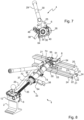
- the main body may include a clamping mechanism secured to the sheath extending toward the first end of the main body, and the first securing member may be mounted on the clamping mechanism.
- the clamping mechanism may be provided with an operating screw, a guide member partially housed in the sheath and provided for guiding the operating screw, and a clamping and locking ring mounted to rotate on the operating screw, between the first end of the main body and the guide member.
- the clamping and locking ring may be disposed in abutment against the guide member and the device may include a locking member mounted locked on the clamping and locking ring together with the guide member.
- the operating screw may be partially housed in an internal space provided in the sheath and have an orifice provided at one end into which a stop member is introduced.
- the second securing member may be mounted so as to be rotatably mounted on a free end of the telescopic insert; and/or the first securing member may be mounted so as to be rotatably mounted on a free end of the operating screw.
- the guide member may comprise a flange-shaped annular wall arranged in support and outside the sheath, and a cylindrical wall projecting from the annular wall and housed in an internal space formed in the sheath by fitting one side of the sheath, and a plurality of holes are formed in the annular wall; and the clamping and locking ring may comprise an annular wall having an external contour which is here serrated and which is intended to come into contact with the annular wall of the guide member.
- the guide member may comprise a threaded internal surface through which the operating screw passes, with one end located opposite the annular wall, and the clamping and locking ring may further comprise a cylindrical wall through which the operating screw passes and having an internal face arranged so as to form a double nut system.
- the invention also relates, according to a second aspect, to an assembly comprising an electrical interconnection device as described above as well as one or more accessories, including at least one first securing member of a first type configured to be mounted at a first end of a main body of the electrical interconnection device and to be mechanically and electrically secured to the top of a rolling rail, at least one second securing member of a second type configured to be mounted at a second end of the main body opposite its first end, on a telescopic insert of the main body, and to be mechanically and electrically secured to the top or bottom of a power rail depending on its orientation, and at least one first securing member of a third type, different from that of the first type, configured to be mounted at the first end of the main body and to be mechanically and electrically secured to the bottom of the rolling rail.
- the method may comprise the step of selecting a first securing member from one of a first type configured to be mounted at a first end of the main body and to be mechanically and electrically secured to the top of the rolling rail, and a third type, different from the first type, configured to be mounted at the first end of the main body and to be mechanically and electrically secured to the bottom of the rolling rail.
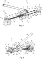
- the invention also relates, according to a fourth aspect, to an electrical interconnection device for earthing railway rails, comprising a main body, at least one first securing member mounted at a first end of the main body and configured to be mechanically and electrically secured to a so-called rolling railway rail, at least one second securing member mounted at a second end of the main body opposite the first end and configured to be mechanically and electrically secured to a so-called supply railway rail, characterized in that the main body has the shape of a single arm provided with a sheath, an insert housed at least partially in the sheath, extending towards the second end of the main body and on which the second securing member is secured, and a clamping mechanism secured to the sheath, extending from the sheath towards the first end of the main body and on which the first securing member is secured, said clamping mechanism being configured to separate the first and second securing members so as to engage them on the respective rolling and power rails, and the electrical interconnection device further comprises a locking member configured
- the main body of the electrical interconnection device according to the invention is formed of a single arm grouping the insert on which the second securing member is mounted, the clamping mechanism on which the first securing member is mounted, and also the sheath interposed between the insert and the clamping mechanism, makes the electrical interconnection device particularly compact and also particularly convenient to use, including the positioning of the first and second securing members on the respective rolling and power supply rails.
- the electrical interconnection device makes it possible, thanks to the clamping mechanism and the locking member of this mechanism, on the one hand to secure the positioning of the first and second securing members on the respective rolling and supply rails and on the other hand, to secure the holding in position of these first and second securing members.
- the electrical interconnection of the rolling and supply rails is made reliable and their earthing is ensured.
- the clamping mechanism may be provided with an operating screw, a guide member partially housed in the sheath and provided for guiding the operating screw, and a clamping and locking ring mounted to rotate on the operating screw, between the first end of the main body and the guide member.
- the clamping and locking ring can be arranged to bear against the guide member and the locking member is mounted locked on the clamping and locking ring together with the guide member.
- the guide member may comprise an annular wall in the form of a flange arranged in support and outside the sheath, and a cylindrical wall projecting from the annular wall and housed in an internal space formed in the sheath by fitting one side of the sheath, and a plurality of holes are formed in the annular wall; and the clamping and locking ring may comprise an annular wall having an external contour which is here serrated and which is intended to come into abutment against the annular wall of the guide member.
- the serrated outer contour may be provided with recesses to allow the introduction of a portion of the locking member so that, when a recess of the outer contour is located opposite a hole in the annular wall of the guide member, the portion of the locking member can pass through both a recess of the outer contour and a respective hole in order to immobilize in rotation the clamping and locking ring together with the guide member.
- the guide member may comprise a threaded internal surface through which the operating screw passes, with one end located opposite the annular wall, and the clamping and locking ring may further comprise a cylindrical wall through which the operating screw passes and having an internal face arranged so as to form a double nut system.
- the operating screw may be partially housed in an internal space provided in the sheath and have an orifice provided at one end into which a stop member is introduced.
- the insert may be telescopic and mounted to be movable in translation and rotation relative to the sheath, with one of said at least one first securing member and said at least one second securing member being mechanically secured to a free end of the telescopic insert; whereby the electrical interconnection device is configured to admit a retracted configuration in which the telescopic insert is introduced into the sheath and a deployed configuration in which the telescopic insert is at least partially extracted from the sheath, with one of said at least one first securing member and said at least one second securing member being configured to be arranged in a predetermined orientation among a plurality of orientations, regardless of the configuration of the electrical interconnection device.
- the overall length of the electrical interconnection device Being able to extend/retract the telescopic insert into the sheath allows the overall length of the electrical interconnection device to be adapted to the distance separating the power rail from the rolling rail on which this electrical interconnection device is engaged via the first and second securing members, for the electrical interconnection of these rails for their earthing.
- the first positioning member is provided with a fixing part projecting from an internal face opposite its external face and by which the first securing member is mounted to move in rotation on the main body.
- the power rail 3 can be located higher than the rolling rails 2. Alternatively, it can be the other way around.
- the first branch 40 is here pressed tightly against one of the lateral faces 17 of the head 12 of the first shoe 6, the second branch 41 is placed in abutment on the upper face 16 of this head 12, and the rim 42 comes into contact with the junction portion 18 of this head 12 which joins the lateral face 17 against which the first branch 40 is in abutment.
- the positioning handle 25 is fixed on the second branch 41 of the first shoe 6, on a face opposite the contact face 44.
- the handle 30 of the gripping handle 29 has a split end 39 into which a projection of the sleeve 30 and a fixing system 49 are introduced, for example of the screw-nut type, to establish the connection between the gripping handle 29, also called a lever, and the sheath 32 of the main body 5.
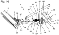
- the guide member 36 comprises an annular wall 63 in the form of a flange and a cylindrical wall 65 projecting from the annular wall 63 and housed in the internal space 75 by fitting into one side of the sheath 32.
- a plurality of holes 64 are formed in the annular wall 63 to receive a shackle of the padlock 38.
- the annular wall 63 is arranged in support and outside the sheath 32.
- the clamping and locking ring 37 comprises an annular wall 68 having an external contour 72 which is here serrated and which is intended to come into contact with the annular wall 63 of the guide member 36.
- Such a serrated external contour 72 is provided with hollows deep enough to allow the introduction of the shackle of the padlock 38 so that, when a hollow of the external contour 72 is located opposite a hole 64 of the annular wall 63 of the guide member 36, the shackle of the padlock 38 can pass through both a hollow of the external contour 72 and a respective hole 64 in order to immobilize in rotation the clamping and locking ring 37 together with the guide member 36.
- the clamping and locking ring 37 further comprises a cylindrical wall 67 through which the operating screw 35 passes and having an internal face 69 arranged so as to form a double nut system here.
- the electrical interconnection device 4 is provided with positioning orifices 73 formed both in the sheath 32 and in the telescopic insert 34, as well as a fixing member 74 formed for example by a pin and passing through the positioning orifices 73 of the sheath 32 and of the telescopic insert 34 when they are opposite each other.
- two pairs of positioning holes 73 are visible so that the telescopic insert 34 can be held in two distinct positions relative to the sheath 32, namely a retracted position or a deployed position of the telescopic insert 34.
- the pairs of positioning holes 73 are provided both on the sheath 32 and on the telescopic insert 34 so that more than one fixing member 74 of the type, for example, a pin can be introduced into these positioning holes 73 when they are opposite each other, in order to maintain the telescopic insert 34 in a predetermined position relative to the sheath 32.
- the telescopic insert 34 may comprise a widened section 77 at one end 76 opposite its free end 56 and forming an internal stop for the sheath 32.
- the sheath 32 may have, on the opposite side where the guide member 36 is located, a narrowed edge 78 at the level of which the telescopic insert 34 projects.
- the telescopic insert 34 can slide in the internal space 75 of the sheath 32 without being able to be completely extracted from the sheath 32 since the widened section 77 comes into abutment against the narrowed edge 78.
- the telescopic insert 34 is mounted in the sheath 32 on the side of the sheath 32 where the guide member 36, the clamping and locking ring 37 and the operating screw 35 are located, before the latter are mounted.
- the telescopic insert 34 is movable in rotation, that is to say that it can be rotated inside the sheath 32, in particular to orient the second shoe 8 in a predetermined position among a plurality of positions.
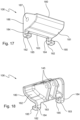
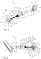
- FIG 8 shows a first variant of use of the electrical interconnection device 4, in which the telescopic insert 34 has been rotated 180 degrees inside the sheath 32 so as to turn the second shoe 8 180 degrees.
- the electrical interconnection device 4 is here visible in the retracted configuration, with the telescopic insert 34 almost completely inserted into the sheath with the exception of its free end 56 to which the second shoe 8 is secured and locked by the fixing member 74.
- the electrical interconnection device 4 is also visible here in the locked configuration with the shackle of the padlock 38 which is locked and engaged in a hollow of the serrated external contour 72 of the clamping and locking ring 37 and in a hole 64 of the guide member 36.
- the clamping mechanism 33 is thus blocked and the operating screw 35 cannot move.
- the first shoe 6 is secured to the head 12 of the rolling rail 2, as on the Figure 2 described above.
- the second shoe 8 has been rotated 180 degrees to allow it to rest and contact the foot 20 at the top of the feed rail 3, rather than on the bottom foot as on the Figure 2 .
- the telescopic insert 34 and the second shoe 8 have been rotated 180 degrees relative to the figure 8 .
- the telescopic insert may include a plurality of positioning holes defining a plurality of deployed positions relative to the sheath.
- the sheath may have only one pair of positioning holes at the location of the insertion of the fastener.
Landscapes
- Engineering & Computer Science (AREA)
- Mechanical Engineering (AREA)
- Train Traffic Observation, Control, And Security (AREA)
- Elimination Of Static Electricity (AREA)
Claims (19)
- Elektrische Verbindungsvorrichtung zur Erdung von Eisenbahnschienen, umfassend einen Hauptkörper (5), mindestens ein erstes Fixierungselement (6, 106), das an einem ersten Ende (7) des Hauptkörpers (5) montiert ist und so konfiguriert ist, dass es mechanisch und elektrisch an eine Rollbahnschiene (2) fixiert werden kann, mindestens ein zweites Fixierungselement (8), das an einem zweiten Ende (9) des Hauptkörpers (5), das dem ersten Ende (7) gegenübersteht, montiert ist und so konfiguriert ist, dass es mechanisch und elektrisch an eine Versorgungsbahnschiene (3) fixiert werden kann, wobei der Hauptkörper (5) mit mindestens einer Hülse (32) und mindestens einem gegenüber der Hülse (32) verschieb- und drehbeweglich montierten Teleskopeinsatz (34) versehen ist, wobei eines von dem mindestens einen ersten Fixierungselement (6, 106) und dem mindestens einen zweiten Fixierungselement (8) mechanisch an ein freies Ende (56) des Teleskopeinsatzes (34) fixiert sind; wodurch die elektrische Verbindungsvorrichtung (4) so konfiguriert ist, dass sie eine eingefahrene Konfiguration, in der der Teleskopeinsatz (34) in die Hülse (32) eingeführt wird, und eine ausgefahrene Konfiguration, in der der Teleskopeinsatz (34) mindestens teilweise aus der Hülse (32) herausgezogen ist, zulässt, dadurch gekennzeichnet, dass eines von dem mindestens einen ersten Fixierungselement (6, 106) und dem mindestens einen zweiten Fixierungselement (8) so konfiguriert ist, dass es unabhängig von der Konfiguration der elektrischen Verbindungsvorrichtung (4) in einer vorbestimmten Ausrichtung aus einer Vielzahl von Ausrichtungen angeordnet ist.
- Vorrichtung nach Anspruch 1, dadurch gekennzeichnet, dass sie mit Positionierungsöffnungen (73), die sowohl in der Hülse (32) als auch im Teleskopeinsatz (34) ausgebildet sind, sowie einem Befestigungselement (74) versehen ist, das in den Positionierungsöffnungen (73) der Hülse (32) und des Teleskopeinsatzes (34) montiert ist, wenn sie sich gegenüberstehen; wodurch der Teleskopeinsatz (34) in einer Vielzahl von unterschiedlichen Positionen relativ zur Hülse (32) gehalten werden kann.
- Vorrichtung nach einem der Ansprüche 1 und 2, dadurch gekennzeichnet, dass der Hauptkörper (5) einen Spannmechanismus (33) umfasst, der an der Hülse (34) fixiert ist, die sich zum ersten Ende (7) des Hauptkörpers (5) hin erstreckt, und das erste Fixierungselement (6, 106) an dem Spannmechanismus (33) montiert ist.
- Vorrichtung nach Anspruch 3, dadurch gekennzeichnet, dass der Spannmechanismus (33) mit einer Manövrierschraube (35), einem Führungselement (36), das teilweise in der Hülse (32) untergebracht ist und zum Führen der Manövrierschraube (35) vorgesehen ist, und einem Klemm- und Verriegelungsring (37) versehen ist, der drehbar auf der Manövrierschraube (35) zwischen dem ersten Ende (7) des Hauptkörpers (5) und dem Führungselement (36) montiert ist.
- Vorrichtung nach Anspruch 4, dadurch gekennzeichnet, dass in einer verriegelten Konfiguration der Vorrichtung der Klemm- und Verriegelungsring (37) am Führungselement (36) anliegend angeordnet ist und die elektrische Verbindungsvorrichtung (4) ein Verriegelungselement (38) umfasst, das zusammen mit dem Führungselement (36) am Klemm- und Verriegelungsring (37) verriegelt montiert ist.
- Vorrichtung nach einem der Ansprüche 4 und 5, dadurch gekennzeichnet, dass die Manövrierschraube (35) teilweise in einem in der Hülse (32) ausgebildeten Innenraum (75) untergebracht ist und eine an einem Ende (70) ausgebildete Öffnung aufweist, in die ein Anschlagelement (71) eingeführt wird.
- Vorrichtung nach einem der Ansprüche 4 bis 6, dadurch gekennzeichnet, dass das zweite Fixierungselement (8) drehbar an einem freien Ende (56) des Teleskopeinsatzes (34) montiert ist; und/oder das erste Fixierungselement (6, 106) drehbar an einem freien Ende (46) der Manövrierschraube (35) montiert ist.
- Vorrichtung nach einem der Ansprüche 4 bis 7, dadurch gekennzeichnet, dass das Führungselement (36) eine ringförmige Wand (63) in Form eines Flansches, der in Anlage und außerhalb der Hülse (32) angeordnet ist, und eine zylindrische Wand (65) umfasst, die von der ringförmigen Wand (63) vorsteht und in einem Innenraum (75) aufgenommen ist, der in der Hülse (32) durch Einstecken auf einer Seite der Hülse (32) ausgebildet ist, und eine Vielzahl von Löchern (64) in der ringförmigen Wand (63) ausgebildet sind; und der Klemm- und Verriegelungsring (37) eine ringförmige Wand (68) mit einer Außenkontur (72) umfasst, die hier gezackt ist und die dazu vorgesehen ist, an der ringförmigen Wand (63) des Führungselements (36) anzuliegen.
- Vorrichtung nach Anspruch 8, dadurch gekennzeichnet, dass die gezackte Außenkontur (72) mit Vertiefungen versehen ist, um das Einführen eines Abschnitts des Verriegelungselements (38) zu ermöglichen, so dass, wenn sich eine Vertiefung der Außenkontur (72) gegenüber einem Loch (64) in der ringförmigen Wand (63) des Führungselements (36) befindet, der Abschnitt des Verriegelungselements (38) sowohl eine Vertiefung der Außenkontur (72) als auch ein jeweiliges Loch (64) durchdringen kann, um den Klemm- und Verriegelungsring (37) zusammen mit dem Führungselement (36) drehfest zu sichern.
- Vorrichtung nach einem der Ansprüche 8 und 9, dadurch gekennzeichnet, dass das Führungselement (36) eine innere Gewindeoberfläche (66) umfasst, die von der Manövrierschraube (35) durchquert wird, mit einem Ende (70), das sich gegenüber der ringförmigen Wand (63) befindet, und der Klemm- und Verriegelungsring (37) ferner eine zylindrische Wand (67) umfasst, die von der Manövrierschraube (35) durchquert wird und eine innere Fläche (69) aufweist, die so ausgebildet ist, dass sie ein Doppelmuttersystem bildet.
- Vorrichtung nach einem der Ansprüche 1 bis 10, dadurch gekennzeichnet, dass sie einen Handgriff (29) umfasst, der aus einem Schaft (30) gebildet ist, der mechanisch über eine Drehverbindung an einer Muffe (31) befestigt ist, die fest am Hauptkörper (5) montiert ist.
- Vorrichtung nach einem der Ansprüche 1 bis 11, dadurch gekennzeichnet, dass das erste Fixierungselement von einem ersten Typ (6) ist und durch ein L-förmiges Teil mit Rand gebildet wird, das mit einem ersten Schenkel (40), einem zweiten Schenkel (41), der sich von dem ersten Schenkel (40) aus erstreckt, und einem Rand (42) versehen ist, der sich von dem ersten Schenkel (40) gegenüber dem zweiten Schenkel (41) erstreckt, wodurch ein Greif- und Aufnahmeraum (43) gebildet wird, der von einer inneren Kontaktfläche (44) begrenzt ist, um die elektrische Verbindung mit der Rollschiene (2) zu gewährleisten; und/oder das zweite Fixierungselement von einem zweiten Typ (8) ist und durch ein L-förmiges Teil gebildet wird, das mit einem ersten Schenkel (50) und einem zweiten Schenkel (51) versehen ist, der sich von dem ersten Schenkel (50) aus erstreckt und somit einen Greif- und Aufnahmeraum (53) bildet, der durch eine innere Kontaktfläche (54) begrenzt ist, um die elektrische Verbindung mit der Versorgungsschiene (3) zu gewährleisten; und/oder das erste Fixierungselement von einem dritten Typ (106) ist und mit einer geneigten und/oder gekrümmten Hauptwand (180) mit einer äußeren Fläche (181), die so konfiguriert ist, dass sie im Wesentlichen eine Kontaktfläche bildet, um an der Rollschiene (2) anzuliegen und diese zu berühren, und mit Befestigungshaken (182) versehen ist, die sich von einem Rand (183) der geneigten und/oder gekrümmten Hauptwand (180) aus erstrecken.
- Vorrichtung nach einem der Ansprüche 1 bis 12, dadurch gekennzeichnet, dass die Rollschiene (2) mit einem Sockel (10), einer Hauptwand (11), die sich im Wesentlichen vertikal von dem Sockel (10) erstreckt, und einem Aufsatz (12) versehen ist, der mit der Hauptwand (11) auf der gegenüberliegenden Seite des Sockels (10) verbunden ist und der dazu vorgesehen ist, eine Rollführung für ein Bahnfahrzeug zu bilden, mit dem Sockel (10), der im Querschnitt eine allgemein dreieckige Form aufweist, die eine untere ebene Fläche (13), zwei Ränder (14), die sich von der unteren ebenen Fläche (13) erstrecken, und zwei geneigte und/oder gekrümmte obere Flächen (15) aufweist, die sich jeweils von einem entsprechenden Rand (14) aus erstrecken und jeweils nach oben und zur Hauptwand (11) hin gerichtet sind, und dass das mindestens eine erste Fixierungselement (106) drehbar an dem Hauptkörper (5) montiert ist und mit einer geneigten und/oder gekrümmten Hauptwand (180) versehen ist, die eine äußere Fläche (181) aufweist, die so konfiguriert ist, dass sie im Wesentlichen eine Kontaktfläche bildet, um in Anlage und Kontakt mit auf einer der geneigten oberen Flächen (15) des Sockels (10) der Rollschiene (2) und auch teilweise auf der Hauptwand (11) in unmittelbarer Nähe der geneigten oberen Fläche (15) des Sockels (10) der Rollschiene (2) zu kommen, wenn das erste Positionierungselement (106) mit der Rollschiene (2) in Eingriff ist.
- Vorrichtung nach Anspruch 13, dadurch gekennzeichnet, dass das mindestens eine erste Fixierungselement (106) mit Befestigungshaken (182) versehen ist, die sich von einem Rand (183) der gekrümmten Hauptwand (180) aus erstrecken und so konfiguriert sind, dass sie mindestens in den Rand (14) des Sockels (10) der Rollschiene (2) eingreifen, von der sich die geneigte obere Fläche (15) erstreckt, an der die äußere Fläche (181) anliegt, wenn das erste Positionierungselement (106) in Eingriff mit der Rollschiene (2) ist.
- Vorrichtung nach Anspruch 14, dadurch gekennzeichnet, dass die Befestigungshaken (182) eine L-Form aufweisen, die einen ersten Schenkel (184), der sich von dem Rand (183) aus erstreckt, und einen zweiten Schenkel (185) aufweist, der sich von dem ersten Schenkel (184) aus erstreckt, die so ausgerichtet sind, dass sich der zweite Schenkel (185) jedes der Befestigungshaken (182) auf der Seite der äußeren Fläche (181) erstreckt, wobei der erste Schenkel (184) jedes Befestigungshakens (182) an dem Rand (14) anliegt, während der zweite Schenkel (185) jedes Befestigungshakens (182) unter der unteren ebenen Fläche (13) in unmittelbarer Nähe des Randes (14) anliegt, wenn das erste Positionierungselement (106) in Eingriff mit der Rollschiene (2) ist.
- Vorrichtung nach Anspruch 15, dadurch gekennzeichnet, dass das erste Positionierungselement (106) mit einem Befestigungsteil (145) versehen ist, das von einer seiner äußeren Fläche (181) gegenüberliegenden inneren Fläche (182) vorsteht und durch das das erste Fixierungselement (106) drehbar am Hauptkörper (5) montiert ist.
- Baugruppe, umfassend eine elektrische Verbindungsvorrichtung (4) nach einem der Ansprüche 1 bis 16 sowie ein oder mehrere Zubehörteile, darunter mindestens ein erstes Fixierungselement eines ersten Typs (6), das so konfiguriert ist, dass es an einem ersten Ende (7) eines Hauptkörpers (5) der elektrischen Verbindungsvorrichtung (4) montiert ist und mechanisch und elektrisch an der Oberseite einer Rollschiene (2) fixiert werden kann, mindestens ein zweites Fixierungselement eines zweiten Typs (8), das so konfiguriert ist, dass es an einem zweiten Ende (9) des Hauptkörpers (5), das seinem ersten Ende (7) gegenüberliegt, an einem Teleskopeinsatz (34) des Hauptkörpers (5) montiert und je nach seiner Ausrichtung mechanisch und elektrisch an der Ober- oder Unterseite einer Versorgungsschiene (3) fixiert werden kann, und mindestens ein erstes Fixierungselement des dritten Typs (106), das sich von dem des ersten Typs unterscheidet und so konfiguriert ist, dass es am ersten Ende (7) des Hauptkörpers (5) montiert und mechanisch und elektrisch an der Unterseite der Rollschiene (2) befestigt werden kann.
- Verfahren zur elektrischen Verbindung und Erdung mindestens einer Rollbahnschiene (2) mit einer Versorgungsbahnschiene (3) mithilfe einer elektrischen Verbindungsvorrichtung (4) nach einem der Ansprüche 1 bis 16, umfassend die Schritte des Bereitstellens einer solchen elektrischen Verbindungsvorrichtung (4) und des Anordnens dieser zwischen der Rollschiene (2) und der Versorgungsschiene (3), des Ineingriffbringens eines ersten Fixierungselements (6; 106) der elektrischen Verbindungsvorrichtung mit der Rollschiene, des Anpassens der Länge der elektrischen Verbindungsvorrichtung durch Ausfahren oder Einfahren eines Teleskopeinsatzes (34) aus oder in eine Hülse (32) eines Hauptkörpers (5) der elektrischen Verbindungsvorrichtung, des Anpassens der Ausrichtung eines zweiten Fixierungselements (8) der elektrischen Verbindungsvorrichtung durch Drehen des Teleskopeinsatzes (34) in und relativ zur Hülse (32) und des Eingriffbringens des zweiten Fixierungselements (8) mit der Versorgungsschiene (2).
- Verfahren nach Anspruch 18, umfassend den Schritt des Auswählens eines ersten Fixierungselements aus einem ersten Typ (6), das so konfiguriert ist, dass es an einem ersten Ende (7) des Hauptkörpers (5) montiert und mechanisch und elektrisch an der Oberseite der Rollschiene (2) fixiert werden kann, und eines dritten Typs (106), der sich von dem des ersten Typs unterscheidet, der so konfiguriert ist, dass er an dem ersten Ende (7) des Hauptkörpers (5) montiert und mechanisch und elektrisch an der Unterseite der Rollschiene (2) fixiert werden kann.
Applications Claiming Priority (1)
| Application Number | Priority Date | Filing Date | Title |
|---|---|---|---|
| PCT/FR2021/050025 WO2022148914A1 (fr) | 2021-01-08 | 2021-01-08 | Dispositif d'interconnexion electrique pour la mise a la terre de rails ferroviaires |
Publications (2)
| Publication Number | Publication Date |
|---|---|
| EP4274763A1 EP4274763A1 (de) | 2023-11-15 |
| EP4274763B1 true EP4274763B1 (de) | 2025-06-25 |
Family
ID=74669185
Family Applications (1)
| Application Number | Title | Priority Date | Filing Date |
|---|---|---|---|
| EP21706637.2A Active EP4274763B1 (de) | 2021-01-08 | 2021-01-08 | Elektrische verbindungsvorrichtung zum erden von eisenbahnschienen |
Country Status (3)
| Country | Link |
|---|---|
| EP (1) | EP4274763B1 (de) |
| ES (1) | ES3047814T3 (de) |
| WO (1) | WO2022148914A1 (de) |
Family Cites Families (4)
| Publication number | Priority date | Publication date | Assignee | Title |
|---|---|---|---|---|
| DE405128C (de) * | 1923-05-12 | 1924-10-30 | Siemens Schuckertwerke G M B H | Kurzschlussvorrichtung fuer Stromschienen elektrischer Bahnen |
| FR2506235A1 (fr) * | 1981-05-19 | 1982-11-26 | Tcl Ste Lyonnaise Transports C | Court-circuiteur de voie, pour reseaux de transport en site propre utilisant une ou plusieurs barres de guidage et/ou un " troisieme rail " pour l'alimentation electrique de traction |
| EP1437257A3 (de) * | 2003-01-13 | 2005-12-07 | Alcan Technology & Management Ltd. | Kurzschlussvorrichting für das Schienennetz einer elektrischen Bahn mit einer Stromschiene zur Speisung des elektrischen Antriebs |
| CN101554842B (zh) * | 2009-05-19 | 2011-04-13 | 西北工业大学 | 一种用于电气化铁路第三轨系统的短路装置 |
-
2021
- 2021-01-08 ES ES21706637T patent/ES3047814T3/es active Active
- 2021-01-08 EP EP21706637.2A patent/EP4274763B1/de active Active
- 2021-01-08 WO PCT/FR2021/050025 patent/WO2022148914A1/fr not_active Ceased
Also Published As
| Publication number | Publication date |
|---|---|
| ES3047814T3 (en) | 2025-12-05 |
| EP4274763A1 (de) | 2023-11-15 |
| WO2022148914A1 (fr) | 2022-07-14 |
Similar Documents
| Publication | Publication Date | Title |
|---|---|---|
| EP2003268B1 (de) | Verbindungs- und Befestigungselement einer Struktur an einer Wand, dazugehörige Struktur und entsprechende Gesamtstruktur | |
| FR2549303A2 (fr) | Connecteur electrique | |
| FR3033018A1 (fr) | Piece de support d'element tubulaire, notamment pour aeronef. | |
| EP0884433A1 (de) | Verbindungseinrichtung für einen Treppenhandlauf | |
| EP4274763B1 (de) | Elektrische verbindungsvorrichtung zum erden von eisenbahnschienen | |
| FR2974377A1 (fr) | Dispositif de type pince dalle multi positions | |
| FR2706147A1 (fr) | Pied de porte-charge pour véhicules. | |
| FR3044173A1 (fr) | Connecteur avec coulisseau d'assistance a la connexion et capot guide-cable | |
| FR2998310A1 (fr) | Ensemble pour un dispositif de serrage d’un tendeur de rail | |
| FR2717211A1 (fr) | Espagnolette de volet battant pour fenêtre ou porte-fenêtre. | |
| EP2682541A2 (de) | Befestigungssystem für eine Säule am Boden | |
| FR2599064A1 (fr) | Dispositif formant borne amovible verrouillable | |
| FR2775943A1 (fr) | Dispositif d'attache et de fixation de plateforme support d'articles sur des boules d'attelage | |
| FR3011694A1 (fr) | Dispositif formant caniveau a securite amelioree | |
| EP0807730B1 (de) | Vorrichtung die den Zugang zu einer bestimmten gesicherten Zone erlaubt | |
| EP2392750A1 (de) | Bewegliche Befestigung zum Abstützen und Befestigen einer Struktur an einer Wand, die mit einem Adapter ausgestattet ist | |
| FR3059738B1 (fr) | Agrafe universelle | |
| EP1038726A1 (de) | Vorrichtung zur Sicherung von Lasten | |
| FR2655393A1 (fr) | Dispositif d'assemblage d'equerre entre des elements tubulaires. | |
| FR2708331A1 (fr) | Dispositif de support extensible. | |
| FR2626414A1 (fr) | Support pour une jonction demontable entre cables | |
| FR2683249A1 (fr) | Piquet pour cloture. | |
| FR2698592A1 (fr) | Agencement pour la fixation amovible d'un siège sur le support plancher d'un véhicule automobile. | |
| FR3110294A1 (fr) | Dispositif d’interconnexion électrique pour mise à la terre d’un conducteur électrique | |
| FR2562126A1 (fr) | Dispositif pour l'accrochage d'une console d'echafaudage a un element de charpente |
Legal Events
| Date | Code | Title | Description |
|---|---|---|---|
| STAA | Information on the status of an ep patent application or granted ep patent |
Free format text: STATUS: UNKNOWN |
|
| STAA | Information on the status of an ep patent application or granted ep patent |
Free format text: STATUS: THE INTERNATIONAL PUBLICATION HAS BEEN MADE |
|
| PUAI | Public reference made under article 153(3) epc to a published international application that has entered the european phase |
Free format text: ORIGINAL CODE: 0009012 |
|
| STAA | Information on the status of an ep patent application or granted ep patent |
Free format text: STATUS: REQUEST FOR EXAMINATION WAS MADE |
|
| 17P | Request for examination filed |
Effective date: 20230713 |
|
| AK | Designated contracting states |
Kind code of ref document: A1 Designated state(s): AL AT BE BG CH CY CZ DE DK EE ES FI FR GB GR HR HU IE IS IT LI LT LU LV MC MK MT NL NO PL PT RO RS SE SI SK SM TR |
|
| DAV | Request for validation of the european patent (deleted) | ||
| DAX | Request for extension of the european patent (deleted) | ||
| GRAP | Despatch of communication of intention to grant a patent |
Free format text: ORIGINAL CODE: EPIDOSNIGR1 |
|
| STAA | Information on the status of an ep patent application or granted ep patent |
Free format text: STATUS: GRANT OF PATENT IS INTENDED |
|
| INTG | Intention to grant announced |
Effective date: 20241002 |
|
| GRAJ | Information related to disapproval of communication of intention to grant by the applicant or resumption of examination proceedings by the epo deleted |
Free format text: ORIGINAL CODE: EPIDOSDIGR1 |
|
| STAA | Information on the status of an ep patent application or granted ep patent |
Free format text: STATUS: REQUEST FOR EXAMINATION WAS MADE |
|
| GRAP | Despatch of communication of intention to grant a patent |
Free format text: ORIGINAL CODE: EPIDOSNIGR1 |
|
| STAA | Information on the status of an ep patent application or granted ep patent |
Free format text: STATUS: GRANT OF PATENT IS INTENDED |
|
| INTC | Intention to grant announced (deleted) | ||
| INTG | Intention to grant announced |
Effective date: 20250205 |
|
| GRAS | Grant fee paid |
Free format text: ORIGINAL CODE: EPIDOSNIGR3 |
|
| GRAA | (expected) grant |
Free format text: ORIGINAL CODE: 0009210 |
|
| STAA | Information on the status of an ep patent application or granted ep patent |
Free format text: STATUS: THE PATENT HAS BEEN GRANTED |
|
| AK | Designated contracting states |
Kind code of ref document: B1 Designated state(s): AL AT BE BG CH CY CZ DE DK EE ES FI FR GB GR HR HU IE IS IT LI LT LU LV MC MK MT NL NO PL PT RO RS SE SI SK SM TR |
|
| REG | Reference to a national code |
Ref country code: GB Ref legal event code: FG4D Free format text: NOT ENGLISH |
|
| REG | Reference to a national code |
Ref country code: CH Ref legal event code: EP |
|
| REG | Reference to a national code |
Ref country code: CH Ref legal event code: EP |
|
| REG | Reference to a national code |
Ref country code: IE Ref legal event code: FG4D Free format text: LANGUAGE OF EP DOCUMENT: FRENCH |
|
| REG | Reference to a national code |
Ref country code: DE Ref legal event code: R096 Ref document number: 602021032791 Country of ref document: DE |
|
| PG25 | Lapsed in a contracting state [announced via postgrant information from national office to epo] |
Ref country code: FI Free format text: LAPSE BECAUSE OF FAILURE TO SUBMIT A TRANSLATION OF THE DESCRIPTION OR TO PAY THE FEE WITHIN THE PRESCRIBED TIME-LIMIT Effective date: 20250625 |
|
| REG | Reference to a national code |
Ref country code: LT Ref legal event code: MG9D |
|
| PG25 | Lapsed in a contracting state [announced via postgrant information from national office to epo] |
Ref country code: GR Free format text: LAPSE BECAUSE OF FAILURE TO SUBMIT A TRANSLATION OF THE DESCRIPTION OR TO PAY THE FEE WITHIN THE PRESCRIBED TIME-LIMIT Effective date: 20250926 Ref country code: NO Free format text: LAPSE BECAUSE OF FAILURE TO SUBMIT A TRANSLATION OF THE DESCRIPTION OR TO PAY THE FEE WITHIN THE PRESCRIBED TIME-LIMIT Effective date: 20250925 |
|
| PG25 | Lapsed in a contracting state [announced via postgrant information from national office to epo] |
Ref country code: BG Free format text: LAPSE BECAUSE OF FAILURE TO SUBMIT A TRANSLATION OF THE DESCRIPTION OR TO PAY THE FEE WITHIN THE PRESCRIBED TIME-LIMIT Effective date: 20250625 |
|
| PG25 | Lapsed in a contracting state [announced via postgrant information from national office to epo] |
Ref country code: HR Free format text: LAPSE BECAUSE OF FAILURE TO SUBMIT A TRANSLATION OF THE DESCRIPTION OR TO PAY THE FEE WITHIN THE PRESCRIBED TIME-LIMIT Effective date: 20250625 |
|
| PG25 | Lapsed in a contracting state [announced via postgrant information from national office to epo] |
Ref country code: RS Free format text: LAPSE BECAUSE OF FAILURE TO SUBMIT A TRANSLATION OF THE DESCRIPTION OR TO PAY THE FEE WITHIN THE PRESCRIBED TIME-LIMIT Effective date: 20250925 |
|
| PG25 | Lapsed in a contracting state [announced via postgrant information from national office to epo] |
Ref country code: LV Free format text: LAPSE BECAUSE OF FAILURE TO SUBMIT A TRANSLATION OF THE DESCRIPTION OR TO PAY THE FEE WITHIN THE PRESCRIBED TIME-LIMIT Effective date: 20250625 |
|
| REG | Reference to a national code |
Ref country code: NL Ref legal event code: MP Effective date: 20250625 |
|
| PG25 | Lapsed in a contracting state [announced via postgrant information from national office to epo] |
Ref country code: NL Free format text: LAPSE BECAUSE OF FAILURE TO SUBMIT A TRANSLATION OF THE DESCRIPTION OR TO PAY THE FEE WITHIN THE PRESCRIBED TIME-LIMIT Effective date: 20250625 |
|
| REG | Reference to a national code |
Ref country code: ES Ref legal event code: FG2A Ref document number: 3047814 Country of ref document: ES Kind code of ref document: T3 Effective date: 20251205 |
|
| PG25 | Lapsed in a contracting state [announced via postgrant information from national office to epo] |
Ref country code: PT Free format text: LAPSE BECAUSE OF FAILURE TO SUBMIT A TRANSLATION OF THE DESCRIPTION OR TO PAY THE FEE WITHIN THE PRESCRIBED TIME-LIMIT Effective date: 20251027 |
|
| REG | Reference to a national code |
Ref country code: AT Ref legal event code: MK05 Ref document number: 1806158 Country of ref document: AT Kind code of ref document: T Effective date: 20250625 |
|
| PG25 | Lapsed in a contracting state [announced via postgrant information from national office to epo] |
Ref country code: IS Free format text: LAPSE BECAUSE OF FAILURE TO SUBMIT A TRANSLATION OF THE DESCRIPTION OR TO PAY THE FEE WITHIN THE PRESCRIBED TIME-LIMIT Effective date: 20251025 |
|
| PG25 | Lapsed in a contracting state [announced via postgrant information from national office to epo] |
Ref country code: AT Free format text: LAPSE BECAUSE OF FAILURE TO SUBMIT A TRANSLATION OF THE DESCRIPTION OR TO PAY THE FEE WITHIN THE PRESCRIBED TIME-LIMIT Effective date: 20250625 Ref country code: SM Free format text: LAPSE BECAUSE OF FAILURE TO SUBMIT A TRANSLATION OF THE DESCRIPTION OR TO PAY THE FEE WITHIN THE PRESCRIBED TIME-LIMIT Effective date: 20250625 |
|
| PG25 | Lapsed in a contracting state [announced via postgrant information from national office to epo] |
Ref country code: CZ Free format text: LAPSE BECAUSE OF FAILURE TO SUBMIT A TRANSLATION OF THE DESCRIPTION OR TO PAY THE FEE WITHIN THE PRESCRIBED TIME-LIMIT Effective date: 20250625 |
|
| PG25 | Lapsed in a contracting state [announced via postgrant information from national office to epo] |
Ref country code: PL Free format text: LAPSE BECAUSE OF FAILURE TO SUBMIT A TRANSLATION OF THE DESCRIPTION OR TO PAY THE FEE WITHIN THE PRESCRIBED TIME-LIMIT Effective date: 20250625 |
|
| PG25 | Lapsed in a contracting state [announced via postgrant information from national office to epo] |
Ref country code: EE Free format text: LAPSE BECAUSE OF FAILURE TO SUBMIT A TRANSLATION OF THE DESCRIPTION OR TO PAY THE FEE WITHIN THE PRESCRIBED TIME-LIMIT Effective date: 20250625 |
|
| PG25 | Lapsed in a contracting state [announced via postgrant information from national office to epo] |
Ref country code: SK Free format text: LAPSE BECAUSE OF FAILURE TO SUBMIT A TRANSLATION OF THE DESCRIPTION OR TO PAY THE FEE WITHIN THE PRESCRIBED TIME-LIMIT Effective date: 20250625 |