EP4274103B1 - Method and apparatus for mapping uplink control information for channel state information feedback - Google Patents
Method and apparatus for mapping uplink control information for channel state information feedback Download PDFInfo
- Publication number
- EP4274103B1 EP4274103B1 EP23199105.0A EP23199105A EP4274103B1 EP 4274103 B1 EP4274103 B1 EP 4274103B1 EP 23199105 A EP23199105 A EP 23199105A EP 4274103 B1 EP4274103 B1 EP 4274103B1
- Authority
- EP
- European Patent Office
- Prior art keywords
- bits
- pmi
- polar code
- cqi
- information
- Prior art date
- Legal status (The legal status is an assumption and is not a legal conclusion. Google has not performed a legal analysis and makes no representation as to the accuracy of the status listed.)
- Active
Links
Images


Classifications
-
- H—ELECTRICITY
- H04—ELECTRIC COMMUNICATION TECHNIQUE
- H04W—WIRELESS COMMUNICATION NETWORKS
- H04W72/00—Local resource management
- H04W72/20—Control channels or signalling for resource management
- H04W72/21—Control channels or signalling for resource management in the uplink direction of a wireless link, i.e. towards the network
-
- H—ELECTRICITY
- H04—ELECTRIC COMMUNICATION TECHNIQUE
- H04L—TRANSMISSION OF DIGITAL INFORMATION, e.g. TELEGRAPHIC COMMUNICATION
- H04L5/00—Arrangements affording multiple use of the transmission path
- H04L5/003—Arrangements for allocating sub-channels of the transmission path
- H04L5/0048—Allocation of pilot signals, i.e. of signals known to the receiver
-
- H—ELECTRICITY
- H03—ELECTRONIC CIRCUITRY
- H03M—CODING; DECODING; CODE CONVERSION IN GENERAL
- H03M13/00—Coding, decoding or code conversion, for error detection or error correction; Coding theory basic assumptions; Coding bounds; Error probability evaluation methods; Channel models; Simulation or testing of codes
- H03M13/03—Error detection or forward error correction by redundancy in data representation, i.e. code words containing more digits than the source words
- H03M13/05—Error detection or forward error correction by redundancy in data representation, i.e. code words containing more digits than the source words using block codes, i.e. a predetermined number of check bits joined to a predetermined number of information bits
- H03M13/13—Linear codes
-
- H—ELECTRICITY
- H04—ELECTRIC COMMUNICATION TECHNIQUE
- H04B—TRANSMISSION
- H04B7/00—Radio transmission systems, i.e. using radiation field
- H04B7/02—Diversity systems; Multi-antenna system, i.e. transmission or reception using multiple antennas
- H04B7/04—Diversity systems; Multi-antenna system, i.e. transmission or reception using multiple antennas using two or more spaced independent antennas
- H04B7/0413—MIMO systems
- H04B7/0417—Feedback systems
-
- H—ELECTRICITY
- H04—ELECTRIC COMMUNICATION TECHNIQUE
- H04B—TRANSMISSION
- H04B7/00—Radio transmission systems, i.e. using radiation field
- H04B7/02—Diversity systems; Multi-antenna system, i.e. transmission or reception using multiple antennas
- H04B7/04—Diversity systems; Multi-antenna system, i.e. transmission or reception using multiple antennas using two or more spaced independent antennas
- H04B7/0413—MIMO systems
- H04B7/0456—Selection of precoding matrices or codebooks, e.g. using matrices antenna weighting
- H04B7/0486—Selection of precoding matrices or codebooks, e.g. using matrices antenna weighting taking channel rank into account
-
- H—ELECTRICITY
- H04—ELECTRIC COMMUNICATION TECHNIQUE
- H04B—TRANSMISSION
- H04B7/00—Radio transmission systems, i.e. using radiation field
- H04B7/02—Diversity systems; Multi-antenna system, i.e. transmission or reception using multiple antennas
- H04B7/04—Diversity systems; Multi-antenna system, i.e. transmission or reception using multiple antennas using two or more spaced independent antennas
- H04B7/06—Diversity systems; Multi-antenna system, i.e. transmission or reception using multiple antennas using two or more spaced independent antennas at the transmitting station
- H04B7/0613—Diversity systems; Multi-antenna system, i.e. transmission or reception using multiple antennas using two or more spaced independent antennas at the transmitting station using simultaneous transmission
- H04B7/0615—Diversity systems; Multi-antenna system, i.e. transmission or reception using multiple antennas using two or more spaced independent antennas at the transmitting station using simultaneous transmission of weighted versions of same signal
- H04B7/0619—Diversity systems; Multi-antenna system, i.e. transmission or reception using multiple antennas using two or more spaced independent antennas at the transmitting station using simultaneous transmission of weighted versions of same signal using feedback from receiving side
- H04B7/0621—Feedback content
- H04B7/063—Parameters other than those covered in groups H04B7/0623 - H04B7/0634, e.g. channel matrix rank or transmit mode selection
-
- H—ELECTRICITY
- H04—ELECTRIC COMMUNICATION TECHNIQUE
- H04B—TRANSMISSION
- H04B7/00—Radio transmission systems, i.e. using radiation field
- H04B7/02—Diversity systems; Multi-antenna system, i.e. transmission or reception using multiple antennas
- H04B7/04—Diversity systems; Multi-antenna system, i.e. transmission or reception using multiple antennas using two or more spaced independent antennas
- H04B7/06—Diversity systems; Multi-antenna system, i.e. transmission or reception using multiple antennas using two or more spaced independent antennas at the transmitting station
- H04B7/0613—Diversity systems; Multi-antenna system, i.e. transmission or reception using multiple antennas using two or more spaced independent antennas at the transmitting station using simultaneous transmission
- H04B7/0615—Diversity systems; Multi-antenna system, i.e. transmission or reception using multiple antennas using two or more spaced independent antennas at the transmitting station using simultaneous transmission of weighted versions of same signal
- H04B7/0619—Diversity systems; Multi-antenna system, i.e. transmission or reception using multiple antennas using two or more spaced independent antennas at the transmitting station using simultaneous transmission of weighted versions of same signal using feedback from receiving side
- H04B7/0621—Feedback content
- H04B7/0632—Channel quality parameters, e.g. channel quality indicator [CQI]
-
- H—ELECTRICITY
- H04—ELECTRIC COMMUNICATION TECHNIQUE
- H04L—TRANSMISSION OF DIGITAL INFORMATION, e.g. TELEGRAPHIC COMMUNICATION
- H04L1/00—Arrangements for detecting or preventing errors in the information received
- H04L1/0001—Systems modifying transmission characteristics according to link quality, e.g. power backoff
- H04L1/0023—Systems modifying transmission characteristics according to link quality, e.g. power backoff characterised by the signalling
- H04L1/0026—Transmission of channel quality indication
-
- H—ELECTRICITY
- H04—ELECTRIC COMMUNICATION TECHNIQUE
- H04L—TRANSMISSION OF DIGITAL INFORMATION, e.g. TELEGRAPHIC COMMUNICATION
- H04L1/00—Arrangements for detecting or preventing errors in the information received
- H04L1/004—Arrangements for detecting or preventing errors in the information received by using forward error control
- H04L1/0045—Arrangements at the receiver end
- H04L1/0047—Decoding adapted to other signal detection operation
-
- H—ELECTRICITY
- H04—ELECTRIC COMMUNICATION TECHNIQUE
- H04L—TRANSMISSION OF DIGITAL INFORMATION, e.g. TELEGRAPHIC COMMUNICATION
- H04L1/00—Arrangements for detecting or preventing errors in the information received
- H04L1/004—Arrangements for detecting or preventing errors in the information received by using forward error control
- H04L1/0056—Systems characterized by the type of code used
- H04L1/0057—Block codes
-
- H—ELECTRICITY
- H04—ELECTRIC COMMUNICATION TECHNIQUE
- H04L—TRANSMISSION OF DIGITAL INFORMATION, e.g. TELEGRAPHIC COMMUNICATION
- H04L1/00—Arrangements for detecting or preventing errors in the information received
- H04L1/004—Arrangements for detecting or preventing errors in the information received by using forward error control
- H04L1/0072—Error control for data other than payload data, e.g. control data
- H04L1/0073—Special arrangements for feedback channel
-
- H—ELECTRICITY
- H04—ELECTRIC COMMUNICATION TECHNIQUE
- H04L—TRANSMISSION OF DIGITAL INFORMATION, e.g. TELEGRAPHIC COMMUNICATION
- H04L1/00—Arrangements for detecting or preventing errors in the information received
- H04L1/004—Arrangements for detecting or preventing errors in the information received by using forward error control
- H04L1/0076—Distributed coding, e.g. network coding, involving channel coding
-
- H—ELECTRICITY
- H04—ELECTRIC COMMUNICATION TECHNIQUE
- H04L—TRANSMISSION OF DIGITAL INFORMATION, e.g. TELEGRAPHIC COMMUNICATION
- H04L5/00—Arrangements affording multiple use of the transmission path
- H04L5/003—Arrangements for allocating sub-channels of the transmission path
- H04L5/0053—Allocation of signalling, i.e. of overhead other than pilot signals
- H04L5/0055—Physical resource allocation for ACK/NACK
-
- H—ELECTRICITY
- H04—ELECTRIC COMMUNICATION TECHNIQUE
- H04L—TRANSMISSION OF DIGITAL INFORMATION, e.g. TELEGRAPHIC COMMUNICATION
- H04L5/00—Arrangements affording multiple use of the transmission path
- H04L5/003—Arrangements for allocating sub-channels of the transmission path
- H04L5/0053—Allocation of signalling, i.e. of overhead other than pilot signals
- H04L5/0057—Physical resource allocation for CQI
-
- H—ELECTRICITY
- H04—ELECTRIC COMMUNICATION TECHNIQUE
- H04L—TRANSMISSION OF DIGITAL INFORMATION, e.g. TELEGRAPHIC COMMUNICATION
- H04L5/00—Arrangements affording multiple use of the transmission path
- H04L5/0091—Signalling for the administration of the divided path, e.g. signalling of configuration information
- H04L5/0094—Indication of how sub-channels of the path are allocated
-
- H—ELECTRICITY
- H04—ELECTRIC COMMUNICATION TECHNIQUE
- H04W—WIRELESS COMMUNICATION NETWORKS
- H04W24/00—Supervisory, monitoring or testing arrangements
- H04W24/10—Scheduling measurement reports ; Arrangements for measurement reports
-
- H—ELECTRICITY
- H04—ELECTRIC COMMUNICATION TECHNIQUE
- H04B—TRANSMISSION
- H04B7/00—Radio transmission systems, i.e. using radiation field
- H04B7/02—Diversity systems; Multi-antenna system, i.e. transmission or reception using multiple antennas
- H04B7/04—Diversity systems; Multi-antenna system, i.e. transmission or reception using multiple antennas using two or more spaced independent antennas
- H04B7/06—Diversity systems; Multi-antenna system, i.e. transmission or reception using multiple antennas using two or more spaced independent antennas at the transmitting station
- H04B7/0613—Diversity systems; Multi-antenna system, i.e. transmission or reception using multiple antennas using two or more spaced independent antennas at the transmitting station using simultaneous transmission
- H04B7/0615—Diversity systems; Multi-antenna system, i.e. transmission or reception using multiple antennas using two or more spaced independent antennas at the transmitting station using simultaneous transmission of weighted versions of same signal
- H04B7/0619—Diversity systems; Multi-antenna system, i.e. transmission or reception using multiple antennas using two or more spaced independent antennas at the transmitting station using simultaneous transmission of weighted versions of same signal using feedback from receiving side
- H04B7/0621—Feedback content
- H04B7/0626—Channel coefficients, e.g. channel state information [CSI]
-
- H—ELECTRICITY
- H04—ELECTRIC COMMUNICATION TECHNIQUE
- H04L—TRANSMISSION OF DIGITAL INFORMATION, e.g. TELEGRAPHIC COMMUNICATION
- H04L1/00—Arrangements for detecting or preventing errors in the information received
- H04L1/0001—Systems modifying transmission characteristics according to link quality, e.g. power backoff
- H04L1/0006—Systems modifying transmission characteristics according to link quality, e.g. power backoff by adapting the transmission format
- H04L1/0007—Systems modifying transmission characteristics according to link quality, e.g. power backoff by adapting the transmission format by modifying the frame length
- H04L1/0008—Systems modifying transmission characteristics according to link quality, e.g. power backoff by adapting the transmission format by modifying the frame length by supplementing frame payload, e.g. with padding bits
-
- H—ELECTRICITY
- H04—ELECTRIC COMMUNICATION TECHNIQUE
- H04L—TRANSMISSION OF DIGITAL INFORMATION, e.g. TELEGRAPHIC COMMUNICATION
- H04L1/00—Arrangements for detecting or preventing errors in the information received
- H04L1/004—Arrangements for detecting or preventing errors in the information received by using forward error control
- H04L1/0041—Arrangements at the transmitter end
-
- H—ELECTRICITY
- H04—ELECTRIC COMMUNICATION TECHNIQUE
- H04L—TRANSMISSION OF DIGITAL INFORMATION, e.g. TELEGRAPHIC COMMUNICATION
- H04L5/00—Arrangements affording multiple use of the transmission path
- H04L5/003—Arrangements for allocating sub-channels of the transmission path
- H04L5/0053—Allocation of signalling, i.e. of overhead other than pilot signals
Definitions
- the disclosure relates to a wireless mobile communication system. More particularly, the disclosure relates to a method in which a terminal measures a radio channel state based on a plurality of reference signals, generates channel state information (CSI) based the measurement, and reports the CSI to a base station in a wireless mobile communication system.
- CSI channel state information
- RANs cloud radio access networks
- D2D device-to-device
- SWSC sliding window superposition coding
- ACM advanced coding modulation
- FBMC filter bank multi carrier
- NOMA non-orthogonal multiple access
- SCMA sparse code multiple access
- the Internet which is a human centered connectivity network where humans generate and consume information
- IoT Internet of Things
- LoE Internet of Everything
- sensing technology “wired/wireless communication and network infrastructure,” “service interface technology,” and “Security technology”
- M2M machine-to-machine
- MTC machine type communication
- 5G communication systems to loT networks.
- technologies such as a sensor network, MTC, and M2M communication may be implemented by beamforming, MIMO, and array antennas.
- Application of a cloud Radio Access Network (RAN) as the above-described Big Data processing technology may also be considered to be as an example of convergence between the 5G technology and the loT technology.
- RAN Radio Access Network
- LTE long term evolution
- LTE-Advanced LTE-Advanced
- HUAWEI ET AL “Details of CSI reporting on PUCCH/PUSCH",3GPP DRAFT; R1-1715466, 3RD GENERATION PARTNERSHIP PROJECT (3GPP), MOBILE COMPETENCE CENTRE ; 650, ROUTE DES LUCIOLES ; F-06921 SOPHIA-ANTIPOLIS CEDEX ; FRANCE,vol. RAN WG1, no. Nagoya, Japan; 20170918 - 20170921 9 September 2017 (2017-09-09), XP051328985 , discloses CSI reporting on PUCCH/PUSCH.
- an aspect of the disclosure is to provide a method of mapping uplink control information (UCI) so as to report channel state information.
- UCI uplink control information
- the disclosure provides methods for overcoming the above-described problems by efficiently designing a UCI mapping rule for encoding a polar code of UCI.
- the invention is set out in the appended set of claims.
- a method of transmitting uplink control information in a wireless communication system includes receiving channel state information (CSI) feedback configuration information from a base station, generating CSI including at least one of a CSI reference signal resource indicator (CRI), a rank indicator (RI), a precoding matrix indicator (PMI), or a channel quality indicator (CQI) based on the CSI feedback configuration information, identifying an information sequence including the CSI, encoding the information sequence using a polar code, and transmitting the encoded information sequence to the base station.
- the CRI and the RI are placed before padding bits in the information sequence and the PMI and the CQI are placed after the padding bits in the information sequence.
- a method of receiving uplink control information in a wireless communication system includes transmitting channel state information (CSI) feedback configuration information to a terminal, receiving an encoded information sequence based on the CSI feedback configuration information from the terminal, and decoding the encoded information sequence using a polar code to identify an information sequence of the encoded information sequence.
- the information sequence consists of CSI in a sequence in which a CSI reference signal resource indicator (CRI) and a rank indicator (RI) are placed before padding bits and a precoding matrix indicator (PMI) and a channel quality indicator (CQI) are placed after the padding bits.
- the CSI includes at least one of the CRI, the RI, the PMI, or the CQI.
- a base station for receiving uplink control information in a wireless communication system.
- the base station includes a transceiver, and at least one processor coupled to the transceiver and configured to control the transceiver to transmit channel state information (CSI) feedback configuration information to a terminal, control the transceiver to receive an encoded information sequence based on the CSI feedback configuration information from the terminal, and decode the encoded information sequence using a polar code to identify an information sequence of the encoded information sequence.
- CSI channel state information
- the information sequence consists of CSI in a sequence in which a CSI reference signal resource indicator (CRI) and a rank indicator (RI) are placed before padding bits and a precoding matrix indicator (PMI) and a channel quality indicator (CQI) are placed after the padding bits.
- the CSI includes at least one of the CRI, the RI, the PMI, or the CQI.
- a terminal and a base station including a plurality of antennas may define a CSI mapping rule in consideration of a polar code sequence. Accordingly, various effects may be provided.
- the ambiguity of UCI encoding may be reduced when the terminal performs CSI reporting, and the number of times that a base station performs UCI blind decoding may be decreased and the base station efficiently identifies UCI.
- a “component surface” includes one or more component surfaces.
- first, second, etc. can be used for describing various elements, the structural elements are not restricted by the terms. The terms are used merely for the purpose to distinguish an element from the other elements. For example, a first element could be termed a second element, and similarly, a second element could be also termed a first element without departing from the scope of the disclosure.
- the term "and/or" includes any and all combinations of one or more associated items.
- a base station is a subject of allocating resources to a terminal, and may be at least one of an eNode B, a Node B, a base station (BS), a radio access unit, a BS controller, and a node on a network.
- a terminal may include a user equipment (UE), a mobile station (MS), a cellular phone, a smart phone, a computer, a multimedia system capable of performing a communication function, a small sensor including a communication function, a wearable device, or an Internet of things (IoT) device.
- UE user equipment
- MS mobile station
- a cellular phone a smart phone
- computer a multimedia system capable of performing a communication function
- a small sensor including a communication function a wearable device
- IoT Internet of things
- a downlink (DL) in various embodiments of the disclosure indicates a wireless transmission path of a signal that a base station transmits to a terminal.
- An uplink (UL) indicates a wireless transmission path of a signal that a terminal transmits to a base station.
- LTE long-term evolution
- LTE-A LTE-advanced
- the various embodiments of the disclosure may be applicable to other communication systems which have similar background or channel forms, such as LTE-A Pro, new radio (NR), or the like.
- LTE-A Pro long-term evolution
- NR new radio
- various embodiments of the disclosure may be modified without departing from the scope of the disclosure, and may be applied to other communication systems, based on the determination by those skilled in the art.
- a wireless communication system has developed to be a broadband wireless communication system that provides a high speed and high quality packet data service, like the communication standards, for example, high speed packet access (HSPA) of 3GPP, LTE or evolved universal terrestrial radio access (E-UTRA), LTE-A, high rate packet data (HRPD) of 3GPP2, ultra mobile broadband (UMB), and 802.16e of IEEE, or the like, beyond the voicebased service provided at the initial stage.
- HSPA high speed packet access
- E-UTRA evolved universal terrestrial radio access
- LTE-A LTE-A
- HRPD high rate packet data
- UMB ultra mobile broadband
- 802.16e 802.16e of IEEE
- An LTE system which is a representative example of the broadband wireless communication system, employs an orthogonal frequency division multiplexing (OFDM) scheme for DL, and employs a single carrier frequency division multiple access (SC-FDMA) scheme for UL.
- OFDM orthogonal frequency division multiplexing
- SC-FDMA single carrier frequency division multiple access
- time-frequency resources for carrying data or control information are allocated and operated in a manner to prevent overlapping of the resources, that is, to establish the orthogonality, between users, so as to identify data or control information of each user.
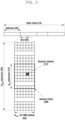
- FIG. 1 is a view illustrating a structure of the time-frequency domain, which is a radio resource region where data or a control channel is transmitted in a downlink of an LTE system, according to an embodiment of the disclosure.
- the basic resource unit is a resource element (RE) 112, and an RE is expressed by an OFDM symbol index and a subcarrier index.
- a resource block (RB) (or physical resource block (PRB)) 108 is defined by consecutive N symb OFDM symbols 102 in the time domain and N RB consecutive subcarriers 110 in the frequency domain. Therefore, one RB 108 includes N symb xN RB REs 112.
- the minimum transmission unit of data is an RB.
- N BW is proportional to a system transmission bandwidth.
- a data rate increases in proportion to the number of RBs scheduled to a terminal.
- a downlink transmission bandwidth and an uplink transmission bandwidth may be different from each other.
- a channel bandwidth may indicate an RF bandwidth corresponding to a system transmission bandwidth.
- Table 1 provided below indicates a relationship between a system transmission bandwidth and a channel bandwidth defined in the LTE system. For example, when LTE system has a channel bandwidth of 10MHz, the transmission bandwidth may include 50 RBs. Table 1 Channel bandwidth 1.4 3 5 10 15 20 BWChannel [MHz] Transmission bandwidth configuration N RB 6 15 25 50 75 100
- Downlink control information is transmitted within first N OFDM symbols in a subframe.
- N ⁇ 1, 2, 3 ⁇ . Therefore, the value of N may be changed for each subframe based on the amount of control information to be transmitted in the current subframe.
- the control information may include a control channel transmission interval indicator indicating the number of OFDM symbols via which control information is to be transmitted, scheduling information associated with downlink data or uplink data, a HARQ ACK/NACK signal, or the like.
- scheduling information associated with downlink data or uplink data may be transmitted from a base station to a terminal via downlink control information (DCI).
- DCI downlink control information
- the DCI are defined in various formats.
- a DCI format may be determined and applied for operation, based on whether scheduling information is for uplink data (UP grant) or for downlink data (DL grant), whether it is compact DCI of which the control information is small, whether spatial multiplexing using multiple antennas is applied, whether it is used for controlling power, and the like.
- DCI format 1 corresponding to scheduling control information on DL grant may be configured to include at least the following control information.
- the DCI goes through a channel coding and modulation process, and is transmitted via a physical downlink control channel (or control information, hereinafter interchangeably used) or an enhanced PDCCH (EPDCCH).
- a physical downlink control channel or control information, hereinafter interchangeably used
- EPDCCH enhanced PDCCH
- DCI transmission may be interchangeably used with the term “PDCCH transmission,” and the expression may be applied to another channel.
- downlink data reception may be interchangeably used with the term “physical downlink shared channel (PDSCH) reception.”
- the DCI is scrambled with a predetermined radio network temporary identifier (RNTI) (or a terminal identifier), independently for each terminal, a cyclic redundancy check (CRC) is added, and channel coding is performed, whereby each independent PDCCH is configured and transmitted.
- RNTI radio network temporary identifier
- CRC cyclic redundancy check
- channel coding is performed, whereby each independent PDCCH is configured and transmitted.
- a PDCCH is mapped and transmitted during the control channel transmission interval.
- the frequency domain mapping position of a PDCCH is determined by the identifier (ID) of each terminal, and is propagated to the entire system transmission band.
- Downlink data is transmitted via a PDSCH, which is a physical channel for downlink data transmission.
- a PDSCH is transmitted after the control channel transmission interval.
- Scheduling information such as a modulation scheme, a specific mapping position in the frequency domain, or the like may be reported by DCI transmitted via a PDCCH.
- a radio frame 214 may include 10 subframes.
- the minimum transmission unit is an SC-FDMA symbol and a single slot 206 includes N symb SC-FDMA symbols 202.
- a single subframe 205 includes two slots.
- the minimum transmission unit is a subcarrier.
- the entire system transmission bandwidth may include a total of New subcarriers 204.
- N BW has a value, which is proportional to a system transmission bandwidth.
- the basic resource unit is a resource element (RE) 212, and an RE is defined by an SC-FDMA symbol index and a subcarrier index.
- An RB 208 is defined by N symb consecutive SC-FDMA symbols in the time domain and N RB consecutive sub-carriers 210 in the frequency domain. Therefore, a single RB includes N symb x N RB REs.
- the minimum transmission unit of data or control information is an RB unit.
- a PUCCH is mapped to a frequency domain corresponding to 1 RB, and may be transmitted during one subframe.
- a timing relationship of a PUCCH or a physical uplink shared channel needs to be defined, which is an uplink physical channel via which a HARQ ACK/NACK is transmitted, wherein the HARQ ACK/NACK corresponds to a PDCCH or an EPDCCH including a semi-persistent scheduling release (SPS release) or a PDSCH which is a physical channel for downlink data transmission.
- SPS release semi-persistent scheduling release
- a PDSCH which is a physical channel for downlink data transmission.
- FDD frequency division duplex
- an HARQ ACK/NACK corresponding to a PDCCH or EPDDCH including SPS release or a PDSCH transmitted in subframe (n-4) is transmitted via a PUCCH or a PUSCH in subframe n.
- a downlink HARQ adapts an asynchronous HARQ scheme in which a point in time for data retransmission is not fixed. That is, when a base station receives a HARQ NACK from a terminal as a feedback for initial transmission data that the base station transmits, the base station freely determines a point in time for retransmission data via a scheduling operation. For the HARQ operation, the terminal buffers data which is determined to be an error as a result of decoding received data, and combines the data and a subsequently retransmitted data.
- the terminal When the terminal receives a PDSCH including downlink data transmitted from the base station in subframe n, the terminal transmits uplink control information including a HARQ ACK or NACK with respect to the downlink data via a PUCCH or a PUSCH in subframe (n+k).
- k is defined differently according to FDD or time division duplex (TDD), and a subframe configuration thereof.
- FDD LTE system FDD LTE system
- TDD LTE system time division duplex
- k is fixed to 4.
- k may be changed according to a subframe configuration and a subframe number.
- uplink HARQ adapts a synchronous HARQ scheme in which a point in time for data transmission is fixed. That is, an uplink/downlink timing relationship among a PUSCH which is a physical channel for uplink data transmission, a PDCCH which is a downlink control channel coming before the PUSCH, and a physical hybrid indicator channel (PHICH) which is a physical channel via which a downlink HARQ ACK/NACK corresponding to the PUSCH are fixed according to the following rules.
- a PUSCH which is a physical channel for uplink data transmission
- PDCCH which is a downlink control channel coming before the PUSCH
- PHICH physical hybrid indicator channel
- the terminal When the terminal receives a PDCCH including uplink scheduling control information transmitted from the base station, or a PHICH via which a downlink HARQ ACK/NACK is transmitted, in subframe n, the terminal transmits uplink data corresponding to the control information via a PUSCH in subframe (n+k).
- k is defined differently according to FDD or TDD of the LTE system, and a configuration thereof.
- FDD LTE system k is fixed to 4.
- k may be changed according to a subframe configuration and a subframe number.
- the terminal when the terminal receives a PHICH carrying a downlink HARQ ACK/NACK from the base station in sub-frame i, the PHICH corresponds to a PUSCH transmitted by the terminal in sub-frame (i-k).
- k is defined differently according to FDD or TDD of the LTE system, and a configuration thereof.
- FDD LTE system In the case of the FDD LTE system, k is fixed to 4.
- k may be changed according to a subframe configuration and a subframe number.
- the descriptions about the wireless communication system is provided from the perspective of an LTE system, and the disclosure is not limited to the LTE system and may be applicable to various wireless communication systems such as NR, 5G, or the like.
- the waveform for uplink transmission in the NR is not limited to SC-FDMA, and cyclic prefix orthogonal frequency division multiplexing (CP-OFDM) is also available.
- FIG. 3 is a diagram illustrating various NR slot structures supported in an NR system according to an embodiment of the disclosure.
- CBs in a single TB may be divided into one or more code block groups (CBGs).
- CBGs code block groups
- an HARQ ACK/NACK for each CBG may be reported and retransmission for each CBG may be performed.
- the remaining configurations are similar to those of the LTE system and LTE-A system.
- a terminal When reporting having same priority collide between different cells, a terminal transmits information associated with a cell having a low cell index, so as to solve the collision problem. Also, when predetermined information is not reported due to collision, remaining periodic channel state reporting is continued using most recently reported corresponding information as the predetermined information. For example, when wideband PMI information is not reported and a most recently reported wideband PMI is 0, a terminal assumes that the wideband PMI is also 0 at the current point in time for reporting, and continues reporting the remaining second PMI and CQI information.
- a PMI2 reported in PUCCH mode 2-1 may be subsampled as shown in Table 6.
- a PMI2 may be reported in 4 bits when a related RI is 1.
- the related RI has a value greater than or equal to 2
- a differential CQI for a second codeword needs to be additionally reported and thus, the PMI2 may be subsampled to 2 bits and may be reported.
- subsampling or joint encoding may be applied to a total of 6 types of periodic feedbacks, including Table 4, Table 5, and Table 6.
- Table 4 Joint encoding of RI and i 1 for PUCCH mode 1-1 submode 1 Value of joint encoding of RI and the first PMI RI Codebook index I RI / PMI 1 i 1 0-7 1 2 I RI / PMI 1 8-15 2 2( I RI / PMI 1 -8) 16-17 3 2( I RI / PMI 1 - 16) 18-19 4 2( I RI / PMI 1 -18) 20-21 5 2( I RI / PMI 1 -20) 22-23 6 2( I RI / PMI 1 -22) 24-25 7 2( I RI / PMI 1 -24) 26 8 0 27-31 reserv ed NA
- Table 5 Joint encoding of RI, i 1 and i 2 for PUCCH mode 1-1 submode 2 RI Relationship between the first PMI value and codebook index i 1 Relationship between the second PMI value and codebook index i 2 total Value of the first PMI I PMI 1 Codebook index
- periodic CSI reporting is transmitted via a short PUCCH or a long PUCCH.
- the short PUCCH includes one or two OFDM symbols.
- the long PUCCH includes three or four OFDM symbols.
- CSI reporting via a short PUCCH or a long PUCCH in NR only single-slot reporting is supported, and multiplexing of CSI parameters (or UCI elements) among multiple slots is not supported unlike LTE and LTE-A. Through the above, multiple reporting time dependency for one CSI reporting may be reduced and performance deterioration caused by error propagation may be prevented.
- a first type is a Typel-SinglePanel codebook on the assumption of a single panel and a low CSI feedback resolution.
- a second type is a Typel-MultiPanel codebook on the assumption of multiple panels and a low CSI feedback resolution.
- a third type is a Typell codebook on the assumption of a single panel and a high CSI feedback resolution.
- Each type of codebook may be defined by some or all of the following parameters.
- each type of codebook may be set to one of two modes.
- a first mode is a mode in which one beam group includes one beam direction. In this instance, i 2 indicates only co-phasing information.
- a second mode is a mode in which one beam group includes one or more beam directions. In this instance, i 2 indicates beam selection information and co-phasing information.
- payload listed in Tables provided below may be required to perform PMI reporting, according to settings associated with a codebook type, a parameter, a mode, or wideband/subband reporting.
- Table 7 lists i 1 payload (i.e., information associated with a wideband) for Typel-SinglePanel codebook.
- Table 8 lists i 2 payload for each subband for Typel-SinglePanel codebook.
- Table 9 lists i 1 payload (i.e., information associated with a wideband) for Typel-MultiPanel codebook.
- Table 10 lists i 2 payload for each subband for Typel-MultiPanel codebook.
- Table 11 lists i 1 payload (i.e., information associated with a wideband) for TypeII codebook.
- Tables 12 to 15 list i 2 payload for Typell codebook. Particularly, Table 12 lists i 2 payload when a QPSK phase and a wideband-only amplitude are used for beamforming.
- Table 13 lists i 2 payload when a QPSK phase and a wideband-and-subband amplitude are used for beamforming.
- Table 14 lists i 2 payload when a 8-PSK phase and a wideband-only amplitude are used for beamforming.
- Table 15 lists i 2 payload when a 8-PSK phase and wideband and subband amplitude are used for beamforming.
- the payload of a PMI varies based on a set value related to each codebook and other UCI elements (e.g., a rank) reported together. That may indicate that a channel coding input sequence may vary according to a situation, and thus, this should be taken into consideration when short and long PUCCH encoding is performed.
- 11 bits are used as a criterion.
- a Reed-Muller code is used for performing channel coding for DCI or UCI information bits with 11 or fewer bits, and a polar code is used for performing channel coding for DCI or UCI information bits with 12 or more bits.
- the information bits may be counted by taking into consideration only a UCI bit stream a 0 , a 1 , a 2 , a 3 ,..., a A -1 having A bits, or may be counted by taking into consideration both a UCI bit stream a 0 ,a 1 ,a 2 ,a 3 ,..., a A- 1 having A bits and parity bits p 0 , p 1 , p 2 , p 3 ,..., p L- 1 having L bits.
- FIG. 6 is a diagram illustrating an example of an encoding method of a polar code according to an embodiment of the disclosure.
- information bits 600 may be encoded by a predetermined Reed-Muller generation matrix 605, thereby being converted to codeword 610.
- the information bits are encoded sequentially from U 0 to U 7 .
- bits are lower bits the number of jointly encoded bits is small, and thus, lower bits have lower reliability. Therefore, some of the lower bits are defined as frozen bits so as to use a predetermined sequence, and the remaining bits are used as data bits, whereby the decoding performance may be improved.
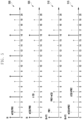
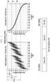
- FIG. 7 is a diagram illustrating an example of a polar code sequence according to an embodiment of the disclosure.
- FIG. 7 it is recognized that decoding reliability increases according to an information bit index, as described in FIG. 6 . Particularly, it is easily observed that the reliability in diagram 700 obtained before sorting, has a certain tendency, although the tendency is not a monotone increasing function or a monotone decreasing function unlike diagram 705 obtained after sorting.
- a polar code sequence 725 may include a frozen bit part 710 including bits having the lowest reliability, a data bit part 715 including bits having medium reliability, and a CRC part 720 having the highest reliability.
- FIG. 8 is a diagram illustrating an example of polar code decoding according to an embodiment of the disclosure.
- a received signal in association with the polar code sequence may be decoded based on the above-described RM generation matrix.
- Decoding is performed by a receiving end including a plurality of basic decoding units in reverse order of reliability of respective information bits.
- Each basic decoding unit sequentially and continuously performs a log-likelihood ratio (LLR) operation for a corresponding node (check node operation), and successive cancelation based thereon (variable node operation). From the perspective of decoding of data bits, it may be schematically illustrated as the tree structure of FIG. 8 .
- LLR log-likelihood ratio
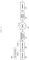
- FIG. 9 is a diagram illustrating an example of a channel coding chain based on a polar code according to an embodiment of the disclosure.
- DCI or UCI information may go through a CRC encoder 900 and may be converted into a polar code sequence 903.
- the polar code sequence 903 may go through a polar encoder 905 and may be changed into codeword, and rate matching is performed, in operation 910 (e.g., via a rate-matching interleaver).
- a ratematched codeword in a circular buffer 915 sequentially go through channel interleaving, in operation 920 (e.g., via a channel interleaver), may be modulated in operation 925 (e.g., via a modulator), and may be mapped to a PDCCH or a PUCCH.
- FIG. 10 is a diagram illustrating an example of a CRC-aided polar (CA-polar) code and an example of a parity-check polar (PC-polar) code according to an embodiment of the disclosure.
- CA-polar CRC-aided polar
- PC-polar parity-check polar
- a PC-polar code 1010 is a method of defining a PC-frozen bit 1012, in addition to a CRC. In this instance, the additional PC-frozen bit is not a fixed value, and may be changed by another data bit. For example, in FIG. 10 , a PC-frozen bit for U 7 may be determined based on values of U 5 and U 6 .
- the efficiency of a CA-polar code and a PC-polar code may be changed based on the payload of an information bit.
- the use of a CA-polar code and a PC-polar code may be determined based on a predetermined information bit payload.
- "polar code" used in the descriptions of the disclosure does not indicate a predetermined polar code, but indicates a general polar code.
- a Reed-Muller code is used for an information payload of 11 or fewer bits
- a polar code is used for an information payload of bits greater than 11 bits.
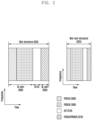
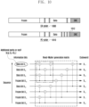
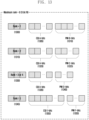
- a base station may estimate the payload of the CQI 1434 or the PMI 1436 after decoding the CRI/RI 1430, and subsequently, decoding is performed by taking into consideration payload other than the payload for CRI/RI 1430, CQI 1434, and PMI 1436 in the data bit part 1410 are the padding bit 1432.
- a base station may estimate the payload of the CQI 1444 or the PMI 1448 after decoding the CRI/RI 1440, and subsequently, decoding is performed by taking into consideration that payload other than the payload for CRI/RI 1440, CQI 1444, and PMI 1438 in the data bit part 1410 are padding bits 1442 and 1446.
- a padding bit is encoded and exists between ⁇ CRI, RI, CQI ⁇ and ⁇ PMI ⁇ .
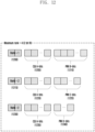
- the data bit part 1410 includes the CQI 1335 with A bits and the PMI 1340 with D bits.
- the PMI 1340 with D bits may be determined with reference to PMI payload values provided in Tables 7 to 15.
- the remaining parts other than the RI/CRI 1330, the CQI 1335, or the PMI 1340 in the data bit part 1410 may be filled with the padding bits 1442 and 1446.
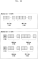
- the data bit part 1410 includes the CQI 1350 with E bits and the PMI 1355 with F bits.
- the PMI 1355 with F bits may be determined with reference to PMI payload values provided in Tables 7 to 15.
- the remaining parts other than the RI/CRI 1345, the CQI 1350, or the PMI 1355 in the data bit part 1410 may be filled with the padding bits 1442 and 1446.
- the base station decodes the CRC 1415, and may determine whether entire polar code sequence decoding is successfully performed.
- the CQI with A bits represents the channel quality of a single codeword, and thus, payload is not changed based on a rank.
- rank is 5, 6, 7, or 8
- the channel quality of two codewords may be represented, and thus, the payload may need to be increased.
- E bits CQI payload that satisfies A ⁇ E ⁇ 2A may be allocated. It should be taken into consideration that a PMI with B, C, D, or F bits may be changed based on the rank.
- the polar code sequence mapping methods assume that the payload of UCI elements is greater than or equal to 12 bits (K>11).
- the terminal may need to map UCI based on a Reed-Muller code, as opposed to the above embodiments.
- K may be determined based on the total sum of actually meaningful UCI elements (i.e., the total sum of the payload of at least one of a CRI, an RI, a CQI, and a PMI).
- the relative positions of the CRI/RI or CQI and PMI may be variable when they are actually applied.
- the relative positions of the CRI/RI/CQI/PMI and padding bits need to be importantly taken into consideration.
- a padding bit is used for ease of description.
- the padding bit may be expressed as various terms, such as an additional frozen bit, a remaining UCI bit index, or the like for actual use.
- At least one of UCI elements may be interchangeably replaced with a CRI and/or a CSI-RSRP or a synchronization signal block index (SSBI) and/or an SSB-RSRP.
- the CRI and the SSBI may be a list of indices including one or more CRIs or SSBIs, and also the CSI-RSRP and the SSB-RSRP may indicate RSRPs associated with CSI-RSs or SSBs indicated by corresponding index lists.
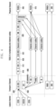
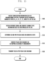
- FIG. 15 is a flowchart illustrating the operation of generating a polar code sequence and transmitting a PUCCH according to an embodiment of the disclosure.
- a terminal receives the maximum MIMO layer (maximum RI), a codebook related parameter (number of ports, N g , N 1 , N 2 , O 1 , O 2 , mode, codebook type, and the like), and reference signal configuration information from a base station, in operation 1500.
- the base station receives a reference signal according to the configuration information, and generates channel state information such as a CRI, an RI, a PMI, a CQI, and the like, in operation 1505.
- the terminal determines payload for reporting the RI, PMI, or CQI, based on the CQI or RI determined when the channel state information are determined, in operation 1510.
- the terminal generates a polar code sequence according to one of the CSI mapping methods according to the embodiments, in operation 1515.
- the polar code sequence is transmitted to the base station via a PUCCH after polar code encoding, in operation 1520.
- FIGS. 16 and 17 a transmitter, a receiver, and a processor of each of the terminal and the base station are illustrated in FIGS. 16 and 17 .
- a receiver, a processor, and a transmitter of each of the base station and the terminal operate according to a corresponding embodiment.
- FIG. 16 is a block diagram of the configuration of a terminal according to an embodiment of the disclosure.
- the terminal of the disclosure may include a terminal receiver 1600, a terminal transmitter 1604, and a terminal processor 1602.
- the terminal receiver 1600 and the terminal transmitter 1604 are commonly called a transceiver in the embodiments of the disclosure.
- the transceiver may transmit and receive a signal to/from a base station.
- the signal may include control information and data.
- the transceiver includes an RF transmitter that up-converts and amplifies the frequency of a transmitted signal, an RF receiver that low-noise amplifies a received signal and down-converts the frequency, and the like.
- the transceiver outputs, to the terminal processor 1602, a signal received via a radio channel, and transmits a signal output from the terminal processor 1602 via a radio channel.
- the terminal processor 1602 may control a series of processes such that the terminal operates according to the above-described embodiments of the disclosure. For example, the terminal receiver 1600 receives configuration information for each CSI reporting from the base station, and the terminal processor 1602 may perform control so as to interpret a CSI mapping method according to the configuration. Subsequently, the terminal transmitter 1604 may transmit a PUCCH generated according to the CSI mapping method.
- FIG. 17 is a block diagram of the configuration of a base station according to an embodiment of the disclosure.
- the base station of the disclosure may include a base station receiver 1701, a base station transmitter 1705, and a base station processor 1703.
- the base station receiver 1701 and the base station transmitter 1705 are commonly called a transceiver in the embodiments of the disclosure.
- the transceiver may transmit and receive a signal to/from a terminal.
- the signal may include control information and data.
- the transceiver includes an RF transmitter that up-converts and amplifies a frequency of a transmitted signal, an RF receiver that low-noise amplifies a received signal and down-converts the frequency, and the like.
- the transceiver outputs, to the base station processor 1703, a signal received via a radio channel, and transmits a signal output from the base station processor 1703 via a radio channel.
- the base station processor 1703 may control a series of processes such that the base station operates according to the above-described embodiments of the disclosure.
- the base station processor 1703 may determine a PUCCH decoding method based on configuration information related to CSI generation which has been known to the terminal. Subsequently, the base station receiver 1701 decodes a PUCCH received according to the embodiments.
- each embodiment may be used in combinations.
- a base station and a terminal may operate based on the combination of a part of the first embodiment and a part of the second embodiment of the disclosure.
- other modifications based on the technical ideas of the embodiments may be applied to various systems, such as an FDD LTE system, a TDD LTE system, a 5G or NR system, and the like.
Landscapes
- Engineering & Computer Science (AREA)
- Signal Processing (AREA)
- Computer Networks & Wireless Communication (AREA)
- Quality & Reliability (AREA)
- Physics & Mathematics (AREA)
- Probability & Statistics with Applications (AREA)
- Theoretical Computer Science (AREA)
- Mathematical Physics (AREA)
- Mobile Radio Communication Systems (AREA)
Applications Claiming Priority (3)
| Application Number | Priority Date | Filing Date | Title |
|---|---|---|---|
| KR1020170116570A KR102488581B1 (ko) | 2017-09-12 | 2017-09-12 | 채널상태정보 보고를 위한 상향링크 컨트롤 정보 맵핑 방법 및 장치 |
| EP18192767.4A EP3454491B1 (en) | 2017-09-12 | 2018-09-05 | Method and apparatus for mapping uplink control information for channel state information feedback |
| EP21158794.4A EP3863200B1 (en) | 2017-09-12 | 2018-09-05 | Method and apparatus for mapping uplink control information for channel state information feedback |
Related Parent Applications (3)
| Application Number | Title | Priority Date | Filing Date |
|---|---|---|---|
| EP18192767.4A Division EP3454491B1 (en) | 2017-09-12 | 2018-09-05 | Method and apparatus for mapping uplink control information for channel state information feedback |
| EP21158794.4A Division EP3863200B1 (en) | 2017-09-12 | 2018-09-05 | Method and apparatus for mapping uplink control information for channel state information feedback |
| EP21158794.4A Division-Into EP3863200B1 (en) | 2017-09-12 | 2018-09-05 | Method and apparatus for mapping uplink control information for channel state information feedback |
Publications (4)
| Publication Number | Publication Date |
|---|---|
| EP4274103A2 EP4274103A2 (en) | 2023-11-08 |
| EP4274103A3 EP4274103A3 (en) | 2024-01-24 |
| EP4274103C0 EP4274103C0 (en) | 2025-07-02 |
| EP4274103B1 true EP4274103B1 (en) | 2025-07-02 |
Family
ID=63528526
Family Applications (3)
| Application Number | Title | Priority Date | Filing Date |
|---|---|---|---|
| EP23199105.0A Active EP4274103B1 (en) | 2017-09-12 | 2018-09-05 | Method and apparatus for mapping uplink control information for channel state information feedback |
| EP21158794.4A Active EP3863200B1 (en) | 2017-09-12 | 2018-09-05 | Method and apparatus for mapping uplink control information for channel state information feedback |
| EP18192767.4A Active EP3454491B1 (en) | 2017-09-12 | 2018-09-05 | Method and apparatus for mapping uplink control information for channel state information feedback |
Family Applications After (2)
| Application Number | Title | Priority Date | Filing Date |
|---|---|---|---|
| EP21158794.4A Active EP3863200B1 (en) | 2017-09-12 | 2018-09-05 | Method and apparatus for mapping uplink control information for channel state information feedback |
| EP18192767.4A Active EP3454491B1 (en) | 2017-09-12 | 2018-09-05 | Method and apparatus for mapping uplink control information for channel state information feedback |
Country Status (10)
| Country | Link |
|---|---|
| US (2) | US11129145B2 (pl) |
| EP (3) | EP4274103B1 (pl) |
| KR (2) | KR102488581B1 (pl) |
| CN (2) | CN109495230B (pl) |
| AU (2) | AU2018332394B2 (pl) |
| ES (1) | ES2866409T3 (pl) |
| PH (1) | PH12020500482A1 (pl) |
| PL (1) | PL3454491T3 (pl) |
| PT (1) | PT3454491T (pl) |
| WO (1) | WO2019054686A1 (pl) |
Families Citing this family (33)
| Publication number | Priority date | Publication date | Assignee | Title |
|---|---|---|---|---|
| CN108282882B (zh) * | 2017-01-06 | 2021-06-22 | 华为技术有限公司 | 信息传输方法、终端设备及接入网设备 |
| KR102812369B1 (ko) * | 2017-02-23 | 2025-05-26 | 삼성전자주식회사 | 스케줄링을 위한 전자 장치 및 방법 |
| KR102488581B1 (ko) | 2017-09-12 | 2023-01-13 | 삼성전자 주식회사 | 채널상태정보 보고를 위한 상향링크 컨트롤 정보 맵핑 방법 및 장치 |
| US11387964B2 (en) * | 2017-10-10 | 2022-07-12 | Telefonaktiebolaget Lm Ericsson (Publ) | PUCCH configuration with HARQ codebook size |
| WO2019071434A1 (en) | 2017-10-10 | 2019-04-18 | Zte Corporation | POLAR CODING TECHNIQUES |
| CN114244470B (zh) | 2017-11-17 | 2023-11-21 | 中兴通讯股份有限公司 | 信道状态信息csi编码方法及装置、存储介质和处理器 |
| US11588589B2 (en) * | 2018-03-30 | 2023-02-21 | Lg Electronics Inc. | Method for performing sidelink communication on basis of polar code and device therefor |
| WO2020144890A1 (ja) * | 2019-01-10 | 2020-07-16 | パナソニック インテレクチュアル プロパティ コーポレーション オブ アメリカ | 基地局、端末及び通信方法 |
| KR20200114828A (ko) * | 2019-03-29 | 2020-10-07 | 삼성전자주식회사 | 무선 통신 시스템에서 사이드링크 피드백 채널의 신호 처리를 위한 방법 및 장치 |
| US11742909B2 (en) | 2019-06-05 | 2023-08-29 | Cohere Technologies, Inc. | Reciprocal geometric precoding |
| WO2021044190A1 (en) | 2019-09-04 | 2021-03-11 | Nokia Technologies Oy | Channel state information overhead reduction for multi-transmission reception point/panel and cell free multiple input, multiple output |
| CN113302968A (zh) | 2019-09-23 | 2021-08-24 | Oppo广东移动通信有限公司 | 确定信道状态信息报告的优先级的方法及装置、用户终端 |
| US11950237B2 (en) * | 2019-09-24 | 2024-04-02 | Qualcomm Incorporated | Sequence based physical uplink control channel transmission |
| KR20210057576A (ko) * | 2019-11-12 | 2021-05-21 | 삼성전자주식회사 | 밀리미터파 대역의 다중 모드 장치를 위한 송수신 방법 및 장치 |
| US20210160011A1 (en) * | 2019-11-25 | 2021-05-27 | Samsung Electronics Co., Ltd. | Method and device for transmitting/receiving uplink control information in wireless communication system |
| CN113258972B (zh) * | 2020-02-13 | 2022-12-02 | 大唐移动通信设备有限公司 | 一种直通链路的信道状态信息反馈及接收方法、装置、介质 |
| CN114930746B (zh) * | 2020-02-14 | 2024-12-24 | 中兴通讯股份有限公司 | 信道状态信息反馈信息的传输和配置 |
| US11387880B2 (en) * | 2020-02-28 | 2022-07-12 | Qualcomm Incorporated | Channel state information feedback using channel compression and reconstruction |
| CN111787510A (zh) * | 2020-07-06 | 2020-10-16 | 嘉兴国电通新能源科技有限公司 | 基于网络编码的d2d视频传输优化方法 |
| CN119298962A (zh) * | 2020-10-14 | 2025-01-10 | 苹果公司 | 基于ue能力的csi报告配置 |
| US11991695B2 (en) * | 2020-10-23 | 2024-05-21 | Apple Inc. | Handlingtime-varying packet size in downlink |
| CN112291016B (zh) * | 2020-10-30 | 2021-09-17 | 台州科技职业学院 | 非正交调制下的伪正交线路编码实现标签信号调制方法 |
| WO2023060608A1 (en) * | 2021-10-16 | 2023-04-20 | Qualcomm Incorporated | Uplink control information (uci) for non-precoding matrix indicator (pmi) -based channel state information (csi) |
| CN116074879A (zh) * | 2021-10-30 | 2023-05-05 | 上海华为技术有限公司 | 一种信道质量的检测方法和基站 |
| CN114614959B (zh) * | 2022-01-18 | 2024-06-18 | 锐捷网络股份有限公司 | 信号解调方法、装置和计算机可读存储介质及电子设备 |
| US20250202556A1 (en) * | 2022-03-14 | 2025-06-19 | Beijing Xiaomi Mobile Software Co., Ltd. | Information processing method and apparatus, communication device, and storage medium |
| CN116015538B (zh) * | 2022-11-29 | 2025-03-07 | 西北工业大学 | 一种基于Polar码的非正交多址接入通信方法 |
| CN121002796A (zh) * | 2023-05-04 | 2025-11-21 | Lg电子株式会社 | 发送信息块的方法、通信装置、处理装置和存储介质及接收信息块的方法、通信装置、处理装置和存储介质 |
| CN116628015B (zh) * | 2023-05-26 | 2026-03-17 | 中国建设银行股份有限公司 | 数据的处理方法、装置、设备、介质及产品 |
| WO2025118443A1 (en) * | 2023-12-05 | 2025-06-12 | Huawei Technologies Co., Ltd. | Interleaving method and apparatuses |
| US12562754B2 (en) * | 2024-05-02 | 2026-02-24 | Qualcomm Incorporated | Single-index parity check for polar encoding |
| WO2025234796A1 (ko) * | 2024-05-10 | 2025-11-13 | 엘지전자 주식회사 | Ambient iot 통신을 위한 방법 및 그 장치 |
| WO2026059384A1 (ko) * | 2024-09-13 | 2026-03-19 | 엘지전자 주식회사 | 채널 상태 정보 예측을 위한 데이터 수집 방법 및 그 장치 |
Family Cites Families (11)
| Publication number | Priority date | Publication date | Assignee | Title |
|---|---|---|---|---|
| KR101875609B1 (ko) * | 2010-09-26 | 2018-08-02 | 엘지전자 주식회사 | 다중 안테나 지원 무선 통신 시스템에서 효율적인 피드백 방법 및 장치 |
| CN103001679A (zh) | 2011-09-13 | 2013-03-27 | 夏普株式会社 | 信道状态信息反馈方法和用户设备 |
| CN103391174B (zh) | 2012-05-10 | 2019-06-11 | 中兴通讯股份有限公司 | Csi反馈信令的指示配置方法及基站 |
| CN103391156B (zh) | 2012-05-11 | 2016-12-07 | 华为技术有限公司 | 一种信道控制信息的传输方法及通信设备 |
| KR101971079B1 (ko) * | 2012-09-20 | 2019-08-13 | 삼성전자 주식회사 | 이동통신 시스템에서 피드백 송수신 방법 및 장치 |
| KR102258289B1 (ko) * | 2014-05-22 | 2021-05-31 | 삼성전자 주식회사 | 이차원 배열 안테나를 사용하는 이동통신 시스템에서의 채널 피드백의 생성 및 전송 방법 및 장치 |
| CN105391479B (zh) | 2014-08-27 | 2019-04-09 | 中国电信股份有限公司 | 一种lte网络中终端反馈码本的方法、基站及系统 |
| US9722651B2 (en) * | 2015-01-09 | 2017-08-01 | Qualcomm Incorporated | Adaptive channel coding using polarization |
| WO2018070738A1 (en) | 2016-10-10 | 2018-04-19 | Samsung Electronics Co., Ltd. | Method and apparatus for reporting periodic channel state information in mobile communication system using massive array antennas |
| US20180317207A1 (en) * | 2017-04-27 | 2018-11-01 | Mediatek Inc. | Method of efficient downlink control information transmission |
| KR102488581B1 (ko) | 2017-09-12 | 2023-01-13 | 삼성전자 주식회사 | 채널상태정보 보고를 위한 상향링크 컨트롤 정보 맵핑 방법 및 장치 |
-
2017
- 2017-09-12 KR KR1020170116570A patent/KR102488581B1/ko active Active
-
2018
- 2018-09-04 AU AU2018332394A patent/AU2018332394B2/en active Active
- 2018-09-04 WO PCT/KR2018/010259 patent/WO2019054686A1/en not_active Ceased
- 2018-09-04 US US16/120,995 patent/US11129145B2/en active Active
- 2018-09-05 EP EP23199105.0A patent/EP4274103B1/en active Active
- 2018-09-05 EP EP21158794.4A patent/EP3863200B1/en active Active
- 2018-09-05 PL PL18192767T patent/PL3454491T3/pl unknown
- 2018-09-05 ES ES18192767T patent/ES2866409T3/es active Active
- 2018-09-05 PT PT181927674T patent/PT3454491T/pt unknown
- 2018-09-05 EP EP18192767.4A patent/EP3454491B1/en active Active
- 2018-09-06 CN CN201811036454.9A patent/CN109495230B/zh active Active
- 2018-09-06 CN CN202110850978.7A patent/CN113572588B/zh active Active
-
2020
- 2020-03-10 PH PH12020500482A patent/PH12020500482A1/en unknown
-
2021
- 2021-09-17 US US17/478,317 patent/US12022470B2/en active Active
-
2023
- 2023-01-10 KR KR1020230003563A patent/KR102696296B1/ko active Active
- 2023-01-20 AU AU2023200332A patent/AU2023200332B2/en active Active
Also Published As
| Publication number | Publication date |
|---|---|
| KR20190029239A (ko) | 2019-03-20 |
| EP3454491B1 (en) | 2021-02-24 |
| WO2019054686A1 (en) | 2019-03-21 |
| EP3454491A1 (en) | 2019-03-13 |
| AU2023200332A1 (en) | 2023-02-23 |
| AU2023200332B2 (en) | 2024-05-23 |
| ES2866409T3 (es) | 2021-10-19 |
| EP4274103A3 (en) | 2024-01-24 |
| PL3454491T3 (pl) | 2021-07-05 |
| EP3863200C0 (en) | 2023-11-01 |
| PT3454491T (pt) | 2021-03-26 |
| EP4274103A2 (en) | 2023-11-08 |
| EP3863200A1 (en) | 2021-08-11 |
| AU2018332394B2 (en) | 2022-10-20 |
| EP4274103C0 (en) | 2025-07-02 |
| US11129145B2 (en) | 2021-09-21 |
| PH12020500482A1 (en) | 2021-03-01 |
| CN113572588B (zh) | 2024-05-24 |
| US20220007359A1 (en) | 2022-01-06 |
| KR20230010805A (ko) | 2023-01-19 |
| AU2018332394A1 (en) | 2020-02-13 |
| US12022470B2 (en) | 2024-06-25 |
| KR102696296B1 (ko) | 2024-08-20 |
| US20190082435A1 (en) | 2019-03-14 |
| CN109495230B (zh) | 2021-09-07 |
| CN113572588A (zh) | 2021-10-29 |
| CN109495230A (zh) | 2019-03-19 |
| EP3863200B1 (en) | 2023-11-01 |
| KR102488581B1 (ko) | 2023-01-13 |
Similar Documents
| Publication | Publication Date | Title |
|---|---|---|
| US12022470B2 (en) | Method and apparatus for mapping uplink control information for channel state information feedback | |
| US11523383B2 (en) | Method and device for setting plurality of DMRS structures in wireless cellular communication system | |
| CN109565338B (zh) | 无线通信系统中的基站和终端及其执行的方法 | |
| EP3313014B1 (en) | Transmission and reception method and apparatus for transmitting signal using narrowband in wireless cellular communication system | |
| US11470607B2 (en) | Resource allocation method in wireless communication system, data reception method on basis of same and device for same | |
| AU2022204501A1 (en) | Method and apparatus for multiplexing channel state information | |
| CN109644037B (zh) | 上行链路传输的预编码信息信令方法和装置 | |
| KR102330319B1 (ko) | 무선 통신 시스템에서 라디오 링크 모니터링 방법 및 장치 | |
| KR20180058107A (ko) | 셀룰라 통신 시스템에서 상향링크 전송 방법 및 장치 | |
| KR20190129491A (ko) | 무선 셀룰라 통신 시스템에서 제어 정보 송수신 방법 및 장치 | |
| KR20180119265A (ko) | 상향링크 이동통신 시스템을 위한 자원할당 및 프리코딩 방법 및 장치 | |
| CN115134062B (zh) | 无线蜂窝通信系统中设置多个dmrs结构的方法和设备 | |
| KR20180010964A (ko) | 무선 셀룰라 통신 시스템에서 다수의 dmrs 구조에 대한 설정 방법 및 장치 | |
| KR20240049531A (ko) | 무선 셀룰라 통신 시스템에서 데이터 전송 방법 및 장치 |
Legal Events
| Date | Code | Title | Description |
|---|---|---|---|
| PUAI | Public reference made under article 153(3) epc to a published international application that has entered the european phase |
Free format text: ORIGINAL CODE: 0009012 |
|
| STAA | Information on the status of an ep patent application or granted ep patent |
Free format text: STATUS: THE APPLICATION HAS BEEN PUBLISHED |
|
| AC | Divisional application: reference to earlier application |
Ref document number: 3454491 Country of ref document: EP Kind code of ref document: P Ref document number: 3863200 Country of ref document: EP Kind code of ref document: P |
|
| AK | Designated contracting states |
Kind code of ref document: A2 Designated state(s): AL AT BE BG CH CY CZ DE DK EE ES FI FR GB GR HR HU IE IS IT LI LT LU LV MC MK MT NL NO PL PT RO RS SE SI SK SM TR |
|
| REG | Reference to a national code |
Ref country code: DE Ref legal event code: R079 Free format text: PREVIOUS MAIN CLASS: H03M0013130000 Ipc: H04L0001000000 Ref document number: 602018083355 Country of ref document: DE |
|
| PUAL | Search report despatched |
Free format text: ORIGINAL CODE: 0009013 |
|
| AK | Designated contracting states |
Kind code of ref document: A3 Designated state(s): AL AT BE BG CH CY CZ DE DK EE ES FI FR GB GR HR HU IE IS IT LI LT LU LV MC MK MT NL NO PL PT RO RS SE SI SK SM TR |
|
| RIC1 | Information provided on ipc code assigned before grant |
Ipc: H04L 5/00 20060101ALN20231221BHEP Ipc: H03M 13/13 20060101ALI20231221BHEP Ipc: H04L 1/00 20060101AFI20231221BHEP |
|
| STAA | Information on the status of an ep patent application or granted ep patent |
Free format text: STATUS: REQUEST FOR EXAMINATION WAS MADE |
|
| 17P | Request for examination filed |
Effective date: 20240503 |
|
| RBV | Designated contracting states (corrected) |
Designated state(s): AL AT BE BG CH CY CZ DE DK EE ES FI FR GB GR HR HU IE IS IT LI LT LU LV MC MK MT NL NO PL PT RO RS SE SI SK SM TR |
|
| GRAP | Despatch of communication of intention to grant a patent |
Free format text: ORIGINAL CODE: EPIDOSNIGR1 |
|
| STAA | Information on the status of an ep patent application or granted ep patent |
Free format text: STATUS: GRANT OF PATENT IS INTENDED |
|
| RIC1 | Information provided on ipc code assigned before grant |
Ipc: H04L 5/00 20060101ALN20240916BHEP Ipc: H03M 13/13 20060101ALI20240916BHEP Ipc: H04L 1/00 20060101AFI20240916BHEP |
|
| INTG | Intention to grant announced |
Effective date: 20240926 |
|
| GRAJ | Information related to disapproval of communication of intention to grant by the applicant or resumption of examination proceedings by the epo deleted |
Free format text: ORIGINAL CODE: EPIDOSDIGR1 |
|
| STAA | Information on the status of an ep patent application or granted ep patent |
Free format text: STATUS: REQUEST FOR EXAMINATION WAS MADE |
|
| GRAP | Despatch of communication of intention to grant a patent |
Free format text: ORIGINAL CODE: EPIDOSNIGR1 |
|
| STAA | Information on the status of an ep patent application or granted ep patent |
Free format text: STATUS: GRANT OF PATENT IS INTENDED |
|
| INTC | Intention to grant announced (deleted) | ||
| RIC1 | Information provided on ipc code assigned before grant |
Ipc: H04L 5/00 20060101ALN20250102BHEP Ipc: H03M 13/13 20060101ALI20250102BHEP Ipc: H04L 1/00 20060101AFI20250102BHEP |
|
| INTG | Intention to grant announced |
Effective date: 20250130 |
|
| GRAS | Grant fee paid |
Free format text: ORIGINAL CODE: EPIDOSNIGR3 |
|
| GRAA | (expected) grant |
Free format text: ORIGINAL CODE: 0009210 |
|
| STAA | Information on the status of an ep patent application or granted ep patent |
Free format text: STATUS: THE PATENT HAS BEEN GRANTED |
|
| AC | Divisional application: reference to earlier application |
Ref document number: 3454491 Country of ref document: EP Kind code of ref document: P Ref document number: 3863200 Country of ref document: EP Kind code of ref document: P |
|
| AK | Designated contracting states |
Kind code of ref document: B1 Designated state(s): AL AT BE BG CH CY CZ DE DK EE ES FI FR GB GR HR HU IE IS IT LI LT LU LV MC MK MT NL NO PL PT RO RS SE SI SK SM TR |
|
| REG | Reference to a national code |
Ref country code: GB Ref legal event code: FG4D |
|
| REG | Reference to a national code |
Ref country code: CH Ref legal event code: EP |
|
| REG | Reference to a national code |
Ref country code: DE Ref legal event code: R096 Ref document number: 602018083355 Country of ref document: DE |
|
| REG | Reference to a national code |
Ref country code: IE Ref legal event code: FG4D |
|
| U01 | Request for unitary effect filed |
Effective date: 20250708 |
|
| U07 | Unitary effect registered |
Designated state(s): AT BE BG DE DK EE FI FR IT LT LU LV MT NL PT RO SE SI Effective date: 20250714 |
|
| PGFP | Annual fee paid to national office [announced via postgrant information from national office to epo] |
Ref country code: GB Payment date: 20250820 Year of fee payment: 8 |
|
| U20 | Renewal fee for the european patent with unitary effect paid |
Year of fee payment: 8 Effective date: 20250924 |
|
| PG25 | Lapsed in a contracting state [announced via postgrant information from national office to epo] |
Ref country code: IS Free format text: LAPSE BECAUSE OF FAILURE TO SUBMIT A TRANSLATION OF THE DESCRIPTION OR TO PAY THE FEE WITHIN THE PRESCRIBED TIME-LIMIT Effective date: 20251102 |
|
| PG25 | Lapsed in a contracting state [announced via postgrant information from national office to epo] |
Ref country code: NO Free format text: LAPSE BECAUSE OF FAILURE TO SUBMIT A TRANSLATION OF THE DESCRIPTION OR TO PAY THE FEE WITHIN THE PRESCRIBED TIME-LIMIT Effective date: 20251002 |
|
| PG25 | Lapsed in a contracting state [announced via postgrant information from national office to epo] |
Ref country code: HR Free format text: LAPSE BECAUSE OF FAILURE TO SUBMIT A TRANSLATION OF THE DESCRIPTION OR TO PAY THE FEE WITHIN THE PRESCRIBED TIME-LIMIT Effective date: 20250702 |
|
| PG25 | Lapsed in a contracting state [announced via postgrant information from national office to epo] |
Ref country code: GR Free format text: LAPSE BECAUSE OF FAILURE TO SUBMIT A TRANSLATION OF THE DESCRIPTION OR TO PAY THE FEE WITHIN THE PRESCRIBED TIME-LIMIT Effective date: 20251003 |
|
| PG25 | Lapsed in a contracting state [announced via postgrant information from national office to epo] |
Ref country code: CZ Free format text: LAPSE BECAUSE OF FAILURE TO SUBMIT A TRANSLATION OF THE DESCRIPTION OR TO PAY THE FEE WITHIN THE PRESCRIBED TIME-LIMIT Effective date: 20250702 |
|
| PG25 | Lapsed in a contracting state [announced via postgrant information from national office to epo] |
Ref country code: PL Free format text: LAPSE BECAUSE OF FAILURE TO SUBMIT A TRANSLATION OF THE DESCRIPTION OR TO PAY THE FEE WITHIN THE PRESCRIBED TIME-LIMIT Effective date: 20250702 |
|
| PG25 | Lapsed in a contracting state [announced via postgrant information from national office to epo] |
Ref country code: RS Free format text: LAPSE BECAUSE OF FAILURE TO SUBMIT A TRANSLATION OF THE DESCRIPTION OR TO PAY THE FEE WITHIN THE PRESCRIBED TIME-LIMIT Effective date: 20251002 |
|
| PG25 | Lapsed in a contracting state [announced via postgrant information from national office to epo] |
Ref country code: ES Free format text: LAPSE BECAUSE OF FAILURE TO SUBMIT A TRANSLATION OF THE DESCRIPTION OR TO PAY THE FEE WITHIN THE PRESCRIBED TIME-LIMIT Effective date: 20250702 |