EP4273003A2 - Système de miroir de remplacement présentant une gestion de surchauffe de del ir - Google Patents
Système de miroir de remplacement présentant une gestion de surchauffe de del ir Download PDFInfo
- Publication number
- EP4273003A2 EP4273003A2 EP23190391.5A EP23190391A EP4273003A2 EP 4273003 A2 EP4273003 A2 EP 4273003A2 EP 23190391 A EP23190391 A EP 23190391A EP 4273003 A2 EP4273003 A2 EP 4273003A2
- Authority
- EP
- European Patent Office
- Prior art keywords
- led
- controller
- camera
- housing
- display
- Prior art date
- Legal status (The legal status is an assumption and is not a legal conclusion. Google has not performed a legal analysis and makes no representation as to the accuracy of the status listed.)
- Granted
Links
Images


Classifications
-
- B—PERFORMING OPERATIONS; TRANSPORTING
- B60—VEHICLES IN GENERAL
- B60R—VEHICLES, VEHICLE FITTINGS, OR VEHICLE PARTS, NOT OTHERWISE PROVIDED FOR
- B60R1/00—Optical viewing arrangements; Real-time viewing arrangements for drivers or passengers using optical image capturing systems, e.g. cameras or video systems specially adapted for use in or on vehicles
- B60R1/20—Real-time viewing arrangements for drivers or passengers using optical image capturing systems, e.g. cameras or video systems specially adapted for use in or on vehicles
- B60R1/30—Real-time viewing arrangements for drivers or passengers using optical image capturing systems, e.g. cameras or video systems specially adapted for use in or on vehicles providing vision in the non-visible spectrum, e.g. night or infrared vision
-
- B—PERFORMING OPERATIONS; TRANSPORTING
- B60—VEHICLES IN GENERAL
- B60R—VEHICLES, VEHICLE FITTINGS, OR VEHICLE PARTS, NOT OTHERWISE PROVIDED FOR
- B60R1/00—Optical viewing arrangements; Real-time viewing arrangements for drivers or passengers using optical image capturing systems, e.g. cameras or video systems specially adapted for use in or on vehicles
- B60R1/12—Mirror assemblies combined with other articles, e.g. clocks
-
- B—PERFORMING OPERATIONS; TRANSPORTING
- B60—VEHICLES IN GENERAL
- B60R—VEHICLES, VEHICLE FITTINGS, OR VEHICLE PARTS, NOT OTHERWISE PROVIDED FOR
- B60R1/00—Optical viewing arrangements; Real-time viewing arrangements for drivers or passengers using optical image capturing systems, e.g. cameras or video systems specially adapted for use in or on vehicles
- B60R1/20—Real-time viewing arrangements for drivers or passengers using optical image capturing systems, e.g. cameras or video systems specially adapted for use in or on vehicles
- B60R1/22—Real-time viewing arrangements for drivers or passengers using optical image capturing systems, e.g. cameras or video systems specially adapted for use in or on vehicles for viewing an area outside the vehicle, e.g. the exterior of the vehicle
- B60R1/23—Real-time viewing arrangements for drivers or passengers using optical image capturing systems, e.g. cameras or video systems specially adapted for use in or on vehicles for viewing an area outside the vehicle, e.g. the exterior of the vehicle with a predetermined field of view
- B60R1/26—Real-time viewing arrangements for drivers or passengers using optical image capturing systems, e.g. cameras or video systems specially adapted for use in or on vehicles for viewing an area outside the vehicle, e.g. the exterior of the vehicle with a predetermined field of view to the rear of the vehicle
-
- H—ELECTRICITY
- H04—ELECTRIC COMMUNICATION TECHNIQUE
- H04N—PICTORIAL COMMUNICATION, e.g. TELEVISION
- H04N23/00—Cameras or camera modules comprising electronic image sensors; Control thereof
- H04N23/56—Cameras or camera modules comprising electronic image sensors; Control thereof provided with illuminating means
-
- H—ELECTRICITY
- H05—ELECTRIC TECHNIQUES NOT OTHERWISE PROVIDED FOR
- H05B—ELECTRIC HEATING; ELECTRIC LIGHT SOURCES NOT OTHERWISE PROVIDED FOR; CIRCUIT ARRANGEMENTS FOR ELECTRIC LIGHT SOURCES, IN GENERAL
- H05B45/00—Circuit arrangements for operating light-emitting diodes [LED]
- H05B45/40—Details of LED load circuits
- H05B45/44—Details of LED load circuits with an active control inside an LED matrix
- H05B45/46—Details of LED load circuits with an active control inside an LED matrix having LEDs disposed in parallel lines
-
- B—PERFORMING OPERATIONS; TRANSPORTING
- B60—VEHICLES IN GENERAL
- B60R—VEHICLES, VEHICLE FITTINGS, OR VEHICLE PARTS, NOT OTHERWISE PROVIDED FOR
- B60R1/00—Optical viewing arrangements; Real-time viewing arrangements for drivers or passengers using optical image capturing systems, e.g. cameras or video systems specially adapted for use in or on vehicles
- B60R1/12—Mirror assemblies combined with other articles, e.g. clocks
- B60R2001/1253—Mirror assemblies combined with other articles, e.g. clocks with cameras, video cameras or video screens
-
- B—PERFORMING OPERATIONS; TRANSPORTING
- B60—VEHICLES IN GENERAL
- B60R—VEHICLES, VEHICLE FITTINGS, OR VEHICLE PARTS, NOT OTHERWISE PROVIDED FOR
- B60R2300/00—Details of viewing arrangements using cameras and displays, specially adapted for use in a vehicle
- B60R2300/10—Details of viewing arrangements using cameras and displays, specially adapted for use in a vehicle characterised by the type of camera system used
- B60R2300/103—Details of viewing arrangements using cameras and displays, specially adapted for use in a vehicle characterised by the type of camera system used using camera systems provided with artificial illumination device, e.g. IR light source
-
- B—PERFORMING OPERATIONS; TRANSPORTING
- B60—VEHICLES IN GENERAL
- B60R—VEHICLES, VEHICLE FITTINGS, OR VEHICLE PARTS, NOT OTHERWISE PROVIDED FOR
- B60R2300/00—Details of viewing arrangements using cameras and displays, specially adapted for use in a vehicle
- B60R2300/80—Details of viewing arrangements using cameras and displays, specially adapted for use in a vehicle characterised by the intended use of the viewing arrangement
- B60R2300/8046—Details of viewing arrangements using cameras and displays, specially adapted for use in a vehicle characterised by the intended use of the viewing arrangement for replacing a rear-view mirror system
-
- B—PERFORMING OPERATIONS; TRANSPORTING
- B60—VEHICLES IN GENERAL
- B60R—VEHICLES, VEHICLE FITTINGS, OR VEHICLE PARTS, NOT OTHERWISE PROVIDED FOR
- B60R2300/00—Details of viewing arrangements using cameras and displays, specially adapted for use in a vehicle
- B60R2300/80—Details of viewing arrangements using cameras and displays, specially adapted for use in a vehicle characterised by the intended use of the viewing arrangement
- B60R2300/8053—Details of viewing arrangements using cameras and displays, specially adapted for use in a vehicle characterised by the intended use of the viewing arrangement for bad weather conditions or night vision
Definitions
- This disclosure relates to a camera mirror system having night vision.
- RGB camera Some types of cameras, such as an RGB camera, will not display an image that is visible at night.
- One approach to providing a visible image at night is to illuminate the camera's field of view with infrared light-emitting diodes (IR LED).
- IR LED infrared light-emitting diodes
- IR LED systems generate heat as they consume power. If the heat is not sufficiently dissipated, an overheating condition may occur, which can cause damage to the circuitry or generate malfunctions in the system. Solutions have been proposed which cycle the IR LEDs on and off. This may be undesirable for rear facing camera mirror systems of the type employed on commercial trucks.
- a camera mirror system for a vehicle may include, among other things, a camera that has a field of view, a display in communication with the camera that is configured to depict the field of view, and an infrared light-emitting diode (IR LED) that is configured to illuminate the field of view.
- the IR LED may be configured to operate at a temperature.
- the system may further include a controller that is configured to provide at least one of a warning or an IR LED shut down command in response to the temperature exceeding a threshold.
- the field of view may correspond to one of a corner view or a rear-facing field view.
- the display may be configured to display at least one of class II and class IV views illuminated by the IR LED for the rear-facing view.
- the display may be configured to display at least one of class V and class VI views illuminated by the IR LED for the corner view.
- the system may include a temperature sensor that is configured to measure the temperature of the IR LED and includes a camera housing.
- the camera, the IR LED and the temperature sensor may be arranged in the camera housing.
- the camera, the IR LED and the temperature sensor may be configured to be arranged outside of the vehicle.
- the controller may be in communication with the temperature sensor.
- the controller may be arranged in the camera housing.
- the controller may be a first controller and may include a second controller that is in communication with the camera.
- the second controller may include a video processor that is configured to provide a video signal to the display.
- the system may include a camera housing.
- the camera and the IR LED may be arranged in the camera housing and may be configured to be arranged outside the vehicle.
- the controller may be arranged outside the camera housing and may be configured to be arranged inside the vehicle.
- the controller may be configured to sense current from the IR LED and infer the temperature based upon the current.
- the IR LED may be mounted on a first controller.
- the controller may be a second controller that includes a video processor that is configured to provide a video signal to the display.
- the first and second controllers may be connected by a wire bundle that consists of two wires. The current may be provided over the wires.
- the second controller may be configured to command the IR LED on the first controller between multiple output levels over the wire bundle.
- the warning may correspond to a symbol on the display.
- the system may include a switch.
- the IR LED shut down command may be provided by the switch.
- the switch may be configured to be manually operated by a driver to turn the IR LED on and off.
- a method of managing night vision for a vehicle camera mirror system may include, among other things, the steps of powering an infrared light-emitting diode (IR LED), sensing a temperature related to the IR LED, and commanding one of a warning or the IR LED in response to the temperature exceeding a threshold.
- IR LED infrared light-emitting diode
- the powering step may include illuminating a vehicle trailer.
- the method may further include a step of displaying at least one of class II and class IV views illuminated by the IR LED.
- the method may include a camera housing.
- the camera, the IR LED and the temperature sensor may be arranged in the camera housing and outside of the vehicle.
- a controller may be arranged in the camera housing.
- the sensing step may include sensing the temperature with a temperature sensor connected to a printed circuit board to which the IR LED is mounted.
- the sensing step may include sensing a current provided to the IR LED.
- the temperature may be inferred from the current.
- the method may include a step of manually switch off the IR LED after displaying the warning symbol.
- the powering step may include manually switching on the IR LED.
- the camera arm may have a mounting bracket that supports a camera housing.
- the mounting bracket may be metallic.
- the system may also include a camera that is arranged in the camera housing and includes a field of view.
- the system may further include a night vision assembly.
- the night vision assembly may include an infrared light-emitting diode (IR LED) that is configured to illuminate the field of view.
- IR LED infrared light-emitting diode
- the night vision assembly may be secured to the mounting bracket.
- the night vision assembly may include a housing that supports a carrier.
- the night vision assembly may include a metallic housing that supports a metallic carrier.
- the IR LED may be mounted to the carrier, for example, the IR LED may be mounted to the metallic carrier.
- a front window may be arranged over the IR LED and sealed relative to the housing.
- a front window may be arranged over the IR LED and sealed relative to the metallic housing. The front window may be exposed through an aperture in the camera housing.
- a printed circuit board may be arranged in the housing (e.g. metallic housing).
- the printed circuit board may be in communication with the IR LED.
- the housing may be filled with potting material.
- the metallic housing may be filled with potting material.
- FIG. 1 A schematic view of a commercial truck 10 is illustrated in Figure 1 .
- the truck 10 includes a vehicle cab 12 pulling a trailer 14.
- Driver and passenger side camera housings 16, provided as arms, are mounted to the vehicle cab 12. If desired, the camera housings 16 may include conventional mirrors integrated with them as well.
- First and second displays 18 are arranged on each of the driver and passenger sides within the vehicle cab 12 to display class II and class IV views on each side of the vehicle 10. Additional displays may be used, and additional or different class views may be provided by the system, if desired.
- At least one rearward facing camera 20 is arranged within the camera housing 16.
- the camera 20 includes an image capture unit 21 that provides a field of view 22 corresponding to at least one of the class II and class IV views, for example. Multiple cameras also may be used to provide the desired views. Class V and class VI views may also be desirable in order to provide views at the opposite front corner from the driver.
- IR LED infrared light-emitting diode
- a night vision assembly 23 includes a temperature sensor 27 that is provided in close proximity to IR LEDs 24, for example, on a common circuit board 29 with the IR LEDs 24 to provide a first controller 28a.
- the temperature sensor 27 is configured to measure a temperature of the IR LEDs, either directly or indirectly.
- a second controller 28b is in communication with the temperature sensor 27.
- the first and second controllers 28a, 28b may be provided on a common PCB.
- the second controller 28b includes a video processor that provides a video signal containing images from the image capture unit 21 to the display 16.
- the second controller 28b may be located within the camera housing 16 or within the display 18. In the example shown in Figure 2A , the second controller 28b is arrange in the camera housing 16.
- the second controller 28b may also be in communication with the IR LEDs 24 to command the IR LEDs on and off.
- a manual switch 30 may be used by the driver to manually turn on and off the IR LEDs 24.
- the second controller 28b is configured to provide at least one of a warning or an IR LED shut down command in response to the temperature detected by the temperature sensor 27 exceeding a temperature threshold.
- the temperature threshold corresponds to an undesired IR LED temperature at which or near the temperature that the IR LEDs 24 or associated circuitry may become damaged or malfunction.
- a warning of the undesired IR LED temperature is communicated to the driver, such as by displaying a warning symbol 32 on the display 18 or by providing another type of audio and/or visual warning elsewhere.
- FIG. 2B Another example system is shown in Figure 2B , but with the second controller 28b located outside of the camera housing 16.
- the system may function and be configured in a similar manner to the system described above in connection with Figure 2A , if desired.
- the night vision assembly 23 is mounted to a metallic mounted bracket 15 (e.g., aluminum) secured to the vehicle cab 12, as shown in Figure 3A .
- the mounting bracket 15 supports the camera housing 16, which may include a fixed potion 16a and a pivotable portion 16b.
- the camera 20 ( Figs. 2A and 2B ) is arranged in the pivotable portion 16b.
- a pivot member 17 passively or actively enables the pivotable portion 16b to rotate with respect to the fixed portion 16a.
- the night vision assembly 23, which includes the IR LEDs 24, is secured to the mounting bracket 15 to conductively dissipate heat to this large, metallic structure.
- the night vision assembly 23 includes a metallic housing 23a supporting a metallic carrier 23b, which are aluminum in one example.
- the IR LEDs 24 are mounted to the metallic carrier 23b via a metallic board 23e, and a transparent front window 23c is arranged over the IR LEDs 24 and sealed relative to the metallic housing 23a, for example, with glue.
- the front window 23c is exposed through an aperture in the fixed portion 16a so that the desired area may be illuminated with infrared light.
- the printed circuit board 29, which drives the IR LEDs 24, is arranged in the metallic housing 23a and is in communication with the IR LEDs 24.
- the metallic housing 23a is filled with potting material 23d.
- the controller 28b is configured to provide at least one of a warning or an IR LED shut down command in response to the temperature detected by the temperature sensor 27 exceeding a temperature threshold.
- the configuration shown in Figure 2B may use a simplified wiring scheme ( Fig. 3A ) in which a wire bundle 34 interconnecting the first and second controllers 28a, 28b only includes two wires 36 (ground and power) that are used to power the IR LEDs 24 via the first controller 28a.
- the second controller 28b may command the first controller 28a between multiple IR LED output levels, e.g., 100% power and 30% power, using the wire bundle 34. Since only two wires 36 are used, the second controller 28a may detect an over-temperature condition by sensing a reduction in current in the wires 36 as compared to the expected current for the commanded power level. The reduced current is interpreted by the second controller 28b as the IR LEDs being at an undesirably high temperature, and the second controller 28b may display a warning symbol 32, command the IR LEDs 24 automatically to a lower output level, and/or shut the IR LEDs 24 off.
- IR LED output levels e.g., 100% power and 30% power
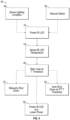
- the method 40 includes powering the IR LEDs 24 when desired, as indicated at block 42. This may be performed by a light sensor automatically sensing a low light condition (block 48) and/or automatically turning on the IR LEDs 24 (e.g., with the vehicle headlights). Alternatively, the switch 30 may be used by the driver to manually turn on and off the IR LEDs 24, as indicated at block 50, whenever desired.
- the temperature sensor 27 senses the IR LED temperature, directly or indirectly, as indicated at block 44. Once the sensed temperature exceeds a threshold, as indicated at block 46, the driver may be warned, for example, by displaying a warning symbol 32 on the display 18. At this point, the driver may manually shut down the IR LEDs 24 using the switch 30, as indicated at block 52, or the IR LEDs may be automatically shut down once a second temperature threshold is exceeded, as indicated at block 54, to discontinue power to the IR LEDs 24 after a predetermined time from the warning.
- the IR LEDs 24 may also be powered at a lower output level (block 56) to reduce the wattage, thereby reducing heat production. In this manner, the integrity of the circuitry is maintained and any system malfunctions are avoided.
- the driver may be notified when the temperature has dropped sufficiently and the night vision system may be used again, or the night vision system may be automatically turned on, or output level increased, by the system.
Landscapes
- Engineering & Computer Science (AREA)
- Multimedia (AREA)
- Mechanical Engineering (AREA)
- Signal Processing (AREA)
- Studio Devices (AREA)
- Lighting Device Outwards From Vehicle And Optical Signal (AREA)
- Closed-Circuit Television Systems (AREA)
Applications Claiming Priority (3)
| Application Number | Priority Date | Filing Date | Title |
|---|---|---|---|
| US201962805535P | 2019-02-14 | 2019-02-14 | |
| PCT/EP2020/053647 WO2020165282A1 (fr) | 2019-02-14 | 2020-02-12 | Système de miroir de remplacement présentant une gestion de surchauffe de del ir |
| EP20705177.2A EP3924219B1 (fr) | 2019-02-14 | 2020-02-12 | Système de miroir de remplacement présentant une gestion de surchauffe de del ir |
Related Parent Applications (2)
| Application Number | Title | Priority Date | Filing Date |
|---|---|---|---|
| EP20705177.2A Division EP3924219B1 (fr) | 2019-02-14 | 2020-02-12 | Système de miroir de remplacement présentant une gestion de surchauffe de del ir |
| EP20705177.2A Division-Into EP3924219B1 (fr) | 2019-02-14 | 2020-02-12 | Système de miroir de remplacement présentant une gestion de surchauffe de del ir |
Publications (3)
| Publication Number | Publication Date |
|---|---|
| EP4273003A2 true EP4273003A2 (fr) | 2023-11-08 |
| EP4273003A3 EP4273003A3 (fr) | 2024-01-17 |
| EP4273003B1 EP4273003B1 (fr) | 2025-04-30 |
Family
ID=69582119
Family Applications (2)
| Application Number | Title | Priority Date | Filing Date |
|---|---|---|---|
| EP23190391.5A Active EP4273003B1 (fr) | 2019-02-14 | 2020-02-12 | Système de miroir de remplacement présentant une gestion de surchauffe de del ir |
| EP20705177.2A Active EP3924219B1 (fr) | 2019-02-14 | 2020-02-12 | Système de miroir de remplacement présentant une gestion de surchauffe de del ir |
Family Applications After (1)
| Application Number | Title | Priority Date | Filing Date |
|---|---|---|---|
| EP20705177.2A Active EP3924219B1 (fr) | 2019-02-14 | 2020-02-12 | Système de miroir de remplacement présentant une gestion de surchauffe de del ir |
Country Status (4)
| Country | Link |
|---|---|
| US (2) | US11153950B2 (fr) |
| EP (2) | EP4273003B1 (fr) |
| CN (1) | CN113412210B (fr) |
| WO (1) | WO2020165282A1 (fr) |
Families Citing this family (10)
| Publication number | Priority date | Publication date | Assignee | Title |
|---|---|---|---|---|
| US11153950B2 (en) * | 2019-02-14 | 2021-10-19 | Orlaco Products B.V. | Replacement mirror system with IR LED overheating management |
| WO2022140161A1 (fr) * | 2020-12-23 | 2022-06-30 | Stoneridge Electronics Ab | Système de miroir de caméra avec capteur de température d'air extérieur |
| US12330564B2 (en) * | 2021-11-12 | 2025-06-17 | Stoneridge Electronics Ab | Automatic IR LED control for camera mirror system |
| US12358430B2 (en) * | 2022-06-23 | 2025-07-15 | Stoneridge Electronics Ab | Modular semi-trailer sensor suite |
| JP2026501117A (ja) * | 2022-12-07 | 2026-01-14 | ストーンリッジ エレクトロニクス アーベー | トレーラカメラディスプレイシステム |
| EP4638196A1 (fr) * | 2022-12-20 | 2025-10-29 | Stoneridge Electronics AB | Système de miroir de caméra avec del ir d'accueil sombre |
| CN115968072A (zh) * | 2022-12-28 | 2023-04-14 | 凌云光技术股份有限公司 | 一种发光系统和方法 |
| DE102023100141A1 (de) * | 2023-01-04 | 2024-07-04 | Man Truck & Bus Se | Sichtsystem für ein Fahrzeug |
| WO2024161516A1 (fr) * | 2023-01-31 | 2024-08-08 | 日産自動車株式会社 | Procédé d'imagerie pour véhicule et système d'imagerie pour véhicule |
| DE102023127318B4 (de) * | 2023-10-06 | 2025-04-30 | Man Truck & Bus Se | Aktivierung und Optimierung eines Nachtmodus in Kamera-Monitor-Anwendungen |
Family Cites Families (36)
| Publication number | Priority date | Publication date | Assignee | Title |
|---|---|---|---|---|
| ES1025450Y (es) | 1993-07-30 | 1994-07-16 | Yotam Sa | "dispositivo iluminador por infrarrojos" |
| DE19521326A1 (de) * | 1995-06-12 | 1996-12-19 | Bosch Siemens Hausgeraete | Verfahren zur Temperaturkompensation der Meßwerte eines Trübungssensors in einer automatischen Wasch- oder Geschirrspülmaschine |
| DE29806638U1 (de) | 1997-06-18 | 1998-06-18 | Leopold Kostal GmbH & Co KG, 58507 Lüdenscheid | Kameraüberwachungseinrichtung |
| JP2000115759A (ja) | 1998-10-05 | 2000-04-21 | Sony Corp | 撮像表示装置 |
| JP4088100B2 (ja) * | 2002-05-14 | 2008-05-21 | 株式会社村上開明堂 | カメラ内蔵型バックミラー装置 |
| JP3948431B2 (ja) | 2003-04-09 | 2007-07-25 | トヨタ自動車株式会社 | 車両用周辺監視装置 |
| FR2858955B1 (fr) | 2003-08-20 | 2007-09-28 | Daimler Chrysler Ag | Source de rayons infrarouges pour vehicules adaptee a un systeme de vision nocturne a infrarouge |
| JP4140898B2 (ja) | 2003-08-20 | 2008-08-27 | 日本電信電話株式会社 | 情報提示装置および情報提示装置の使用方法 |
| US20050243172A1 (en) * | 2004-04-30 | 2005-11-03 | Teiichiro Takano | Rear view mirror with built-in camera |
| JP4242334B2 (ja) * | 2004-11-30 | 2009-03-25 | 本田技研工業株式会社 | 車両周辺監視装置 |
| US7821123B2 (en) * | 2005-09-13 | 2010-10-26 | Delphi Technologies, Inc. | LED array cooling system |
| JP4777759B2 (ja) | 2005-12-01 | 2011-09-21 | 富士フイルム株式会社 | 配線基板及び配線基板接続装置 |
| JP2008124303A (ja) * | 2006-11-14 | 2008-05-29 | Seiko Epson Corp | 半導体発光素子の駆動制御装置、駆動制御装置を有する投写表示装置、および、それらの方法 |
| US8581982B1 (en) * | 2007-07-30 | 2013-11-12 | Flir Systems, Inc. | Infrared camera vehicle integration systems and methods |
| US8340870B2 (en) * | 2008-09-16 | 2012-12-25 | Honda Motor Co., Ltd. | Vehicle maneuver assistance device |
| TWM353849U (en) * | 2008-09-17 | 2009-04-01 | Jyh-Chiang Liou | Integrated driving assistance apparatus |
| JP4951643B2 (ja) * | 2009-03-19 | 2012-06-13 | 株式会社村上開明堂 | 車両用アウターミラー |
| JP4952765B2 (ja) * | 2009-10-21 | 2012-06-13 | トヨタ自動車株式会社 | 車両用夜間視界支援装置 |
| TWM378332U (en) | 2009-11-27 | 2010-04-11 | Yu De Technology Co Ltd | Infrared lighting device |
| US20110273527A1 (en) | 2010-05-06 | 2011-11-10 | Tzu-Chuan Liu | Electronic Infrared Wide-Angle and Safety-Promotion External Vehicular Back Mirror |
| TW201204988A (en) * | 2010-07-26 | 2012-02-01 | Foxsemicon Integrated Tech Inc | LED light emitting device |
| GB201103367D0 (en) * | 2011-02-28 | 2011-04-13 | 360 Vision Technology Ltd | Security camera |
| MY179271A (en) | 2011-09-27 | 2020-11-03 | Zp Enterprise Ltd | A vision enhancement system and a device therefor |
| US8816306B2 (en) * | 2011-12-15 | 2014-08-26 | Battelle Memorial Institute | Infrared light device |
| US9377355B2 (en) * | 2013-02-18 | 2016-06-28 | Eminent Electronic Technology Corp. Ltd. | Optical sensor apparatus and image sensing apparatus integrating multiple functions |
| TWI538509B (zh) * | 2014-08-29 | 2016-06-11 | 晶睿通訊股份有限公司 | 攝影機及其控制方法 |
| CN105306796A (zh) | 2015-10-10 | 2016-02-03 | 安霸半导体技术(上海)有限公司 | 具有定期红外照明和全局快门cmos传感器的夜视设备 |
| US10694107B2 (en) * | 2015-11-13 | 2020-06-23 | Albert Orglmeister | Method and device for eliminating thermal interference for infrared and video-based early fire detection |
| US11313167B2 (en) * | 2016-04-25 | 2022-04-26 | Magna Closures Inc. | System and method for detecting vehicular door movement due to non-contact using obstacle detection |
| JP6511015B2 (ja) * | 2016-05-25 | 2019-05-08 | 株式会社ミツバ | 車両モニタシステム |
| CN206164701U (zh) | 2016-10-24 | 2017-05-10 | 奇瑞汽车股份有限公司 | 一种车载红外夜视装置 |
| JP6720952B2 (ja) * | 2017-11-21 | 2020-07-08 | オムロン株式会社 | 乗員監視装置 |
| JP6780671B2 (ja) * | 2018-03-15 | 2020-11-04 | オムロン株式会社 | 乗員監視装置 |
| US10674052B1 (en) * | 2018-12-12 | 2020-06-02 | Valeo North America, Inc. | Common cover lens for camera and illuminators |
| US11153950B2 (en) * | 2019-02-14 | 2021-10-19 | Orlaco Products B.V. | Replacement mirror system with IR LED overheating management |
| US10893175B2 (en) * | 2019-02-27 | 2021-01-12 | Bendix Commercial Vehicle Systems Llc | Shadowless camera housing |
-
2020
- 2020-02-11 US US16/787,403 patent/US11153950B2/en active Active
- 2020-02-12 CN CN202080013651.8A patent/CN113412210B/zh active Active
- 2020-02-12 EP EP23190391.5A patent/EP4273003B1/fr active Active
- 2020-02-12 EP EP20705177.2A patent/EP3924219B1/fr active Active
- 2020-02-12 WO PCT/EP2020/053647 patent/WO2020165282A1/fr not_active Ceased
-
2021
- 2021-09-27 US US17/486,172 patent/US11665801B2/en active Active
Also Published As
| Publication number | Publication date |
|---|---|
| EP4273003A3 (fr) | 2024-01-17 |
| CN113412210A (zh) | 2021-09-17 |
| US20220015208A1 (en) | 2022-01-13 |
| BR112021015922A2 (pt) | 2021-10-05 |
| EP3924219B1 (fr) | 2023-09-20 |
| US11153950B2 (en) | 2021-10-19 |
| CN113412210B (zh) | 2023-09-12 |
| WO2020165282A1 (fr) | 2020-08-20 |
| US11665801B2 (en) | 2023-05-30 |
| EP4273003B1 (fr) | 2025-04-30 |
| EP3924219A1 (fr) | 2021-12-22 |
| US20200267820A1 (en) | 2020-08-20 |
Similar Documents
| Publication | Publication Date | Title |
|---|---|---|
| US11665801B2 (en) | Replacement mirror system with IR LED overheating management | |
| CN117940316B (zh) | 具有选择性操作用于dms和oms功能的光发射器的车辆车厢内监测系统 | |
| US20240064274A1 (en) | Vehicular vision system with mirror display for vehicle and trailer cameras | |
| JP4815677B2 (ja) | 自動車用ビデオカメラシステム及び自動車用アウトサイドミラー | |
| CN101025857B (zh) | 用于运输车辆的远程状态多功能显示装置 | |
| US20170264797A1 (en) | Driver monitoring system in a motor vehicle | |
| US20120086565A1 (en) | Pulsed indication unit for vehicle | |
| US12528417B2 (en) | Vehicular overhead console integrated with interior mirror and electronic content | |
| TW201329513A (zh) | 抬頭顯示器、車輛及抬頭顯示器的控制方法 | |
| US11840174B2 (en) | Vehicular overhead console with light transmissive panel | |
| US12122298B2 (en) | Camera mirror system with IR LED night vision system | |
| CN118475496A (zh) | 用于安装车辆辅助设备控制器的方法和系统 | |
| JP2019001293A (ja) | 車載用表示装置 | |
| TWI777721B (zh) | 後視鏡系統及車輛 | |
| BR112021015922B1 (pt) | Sistemas de espelho de câmera para um veículo e método de gerenciamento de visão noturna | |
| US20180147989A1 (en) | Method and apparatus for rear-mounted vehicular display control system with integrated back-up camera | |
| CN216153686U (zh) | 后视镜系统及车辆 | |
| JP2024077122A (ja) | 液晶表示ユニットの駆動回路 |
Legal Events
| Date | Code | Title | Description |
|---|---|---|---|
| PUAI | Public reference made under article 153(3) epc to a published international application that has entered the european phase |
Free format text: ORIGINAL CODE: 0009012 |
|
| STAA | Information on the status of an ep patent application or granted ep patent |
Free format text: STATUS: THE APPLICATION HAS BEEN PUBLISHED |
|
| AC | Divisional application: reference to earlier application |
Ref document number: 3924219 Country of ref document: EP Kind code of ref document: P |
|
| AK | Designated contracting states |
Kind code of ref document: A2 Designated state(s): AL AT BE BG CH CY CZ DE DK EE ES FI FR GB GR HR HU IE IS IT LI LT LU LV MC MK MT NL NO PL PT RO RS SE SI SK SM TR |
|
| REG | Reference to a national code |
Ref legal event code: R079 Free format text: PREVIOUS MAIN CLASS: B60R0001260000 Ref country code: DE Ref legal event code: R079 Ref document number: 602020050675 Country of ref document: DE Free format text: PREVIOUS MAIN CLASS: B60R0001260000 Ipc: B60R0001000000 |
|
| PUAL | Search report despatched |
Free format text: ORIGINAL CODE: 0009013 |
|
| AK | Designated contracting states |
Kind code of ref document: A3 Designated state(s): AL AT BE BG CH CY CZ DE DK EE ES FI FR GB GR HR HU IE IS IT LI LT LU LV MC MK MT NL NO PL PT RO RS SE SI SK SM TR |
|
| RIC1 | Information provided on ipc code assigned before grant |
Ipc: B60R 1/00 20220101AFI20231212BHEP |
|
| STAA | Information on the status of an ep patent application or granted ep patent |
Free format text: STATUS: REQUEST FOR EXAMINATION WAS MADE |
|
| 17P | Request for examination filed |
Effective date: 20240716 |
|
| RBV | Designated contracting states (corrected) |
Designated state(s): AL AT BE BG CH CY CZ DE DK EE ES FI FR GB GR HR HU IE IS IT LI LT LU LV MC MK MT NL NO PL PT RO RS SE SI SK SM TR |
|
| GRAP | Despatch of communication of intention to grant a patent |
Free format text: ORIGINAL CODE: EPIDOSNIGR1 |
|
| STAA | Information on the status of an ep patent application or granted ep patent |
Free format text: STATUS: GRANT OF PATENT IS INTENDED |
|
| RIC1 | Information provided on ipc code assigned before grant |
Ipc: B60R 1/00 20220101AFI20241107BHEP |
|
| INTG | Intention to grant announced |
Effective date: 20241125 |
|
| GRAS | Grant fee paid |
Free format text: ORIGINAL CODE: EPIDOSNIGR3 |
|
| GRAA | (expected) grant |
Free format text: ORIGINAL CODE: 0009210 |
|
| STAA | Information on the status of an ep patent application or granted ep patent |
Free format text: STATUS: THE PATENT HAS BEEN GRANTED |
|
| AC | Divisional application: reference to earlier application |
Ref document number: 3924219 Country of ref document: EP Kind code of ref document: P |
|
| AK | Designated contracting states |
Kind code of ref document: B1 Designated state(s): AL AT BE BG CH CY CZ DE DK EE ES FI FR GB GR HR HU IE IS IT LI LT LU LV MC MK MT NL NO PL PT RO RS SE SI SK SM TR |
|
| REG | Reference to a national code |
Ref country code: CH Ref legal event code: EP Ref country code: GB Ref legal event code: FG4D |
|
| REG | Reference to a national code |
Ref country code: DE Ref legal event code: R096 Ref document number: 602020050675 Country of ref document: DE |
|
| REG | Reference to a national code |
Ref country code: IE Ref legal event code: FG4D |
|
| REG | Reference to a national code |
Ref country code: SE Ref legal event code: TRGR |
|
| REG | Reference to a national code |
Ref country code: NL Ref legal event code: FP |
|
| REG | Reference to a national code |
Ref country code: AT Ref legal event code: MK05 Ref document number: 1789759 Country of ref document: AT Kind code of ref document: T Effective date: 20250430 |
|
| PG25 | Lapsed in a contracting state [announced via postgrant information from national office to epo] |
Ref country code: FI Free format text: LAPSE BECAUSE OF FAILURE TO SUBMIT A TRANSLATION OF THE DESCRIPTION OR TO PAY THE FEE WITHIN THE PRESCRIBED TIME-LIMIT Effective date: 20250430 Ref country code: PT Free format text: LAPSE BECAUSE OF FAILURE TO SUBMIT A TRANSLATION OF THE DESCRIPTION OR TO PAY THE FEE WITHIN THE PRESCRIBED TIME-LIMIT Effective date: 20250901 Ref country code: ES Free format text: LAPSE BECAUSE OF FAILURE TO SUBMIT A TRANSLATION OF THE DESCRIPTION OR TO PAY THE FEE WITHIN THE PRESCRIBED TIME-LIMIT Effective date: 20250430 |
|
| REG | Reference to a national code |
Ref country code: LT Ref legal event code: MG9D |
|
| PG25 | Lapsed in a contracting state [announced via postgrant information from national office to epo] |
Ref country code: GR Free format text: LAPSE BECAUSE OF FAILURE TO SUBMIT A TRANSLATION OF THE DESCRIPTION OR TO PAY THE FEE WITHIN THE PRESCRIBED TIME-LIMIT Effective date: 20250731 Ref country code: NO Free format text: LAPSE BECAUSE OF FAILURE TO SUBMIT A TRANSLATION OF THE DESCRIPTION OR TO PAY THE FEE WITHIN THE PRESCRIBED TIME-LIMIT Effective date: 20250730 |
|
| PG25 | Lapsed in a contracting state [announced via postgrant information from national office to epo] |
Ref country code: PL Free format text: LAPSE BECAUSE OF FAILURE TO SUBMIT A TRANSLATION OF THE DESCRIPTION OR TO PAY THE FEE WITHIN THE PRESCRIBED TIME-LIMIT Effective date: 20250430 |
|
| PG25 | Lapsed in a contracting state [announced via postgrant information from national office to epo] |
Ref country code: BG Free format text: LAPSE BECAUSE OF FAILURE TO SUBMIT A TRANSLATION OF THE DESCRIPTION OR TO PAY THE FEE WITHIN THE PRESCRIBED TIME-LIMIT Effective date: 20250430 |
|
| PG25 | Lapsed in a contracting state [announced via postgrant information from national office to epo] |
Ref country code: HR Free format text: LAPSE BECAUSE OF FAILURE TO SUBMIT A TRANSLATION OF THE DESCRIPTION OR TO PAY THE FEE WITHIN THE PRESCRIBED TIME-LIMIT Effective date: 20250430 |
|
| PG25 | Lapsed in a contracting state [announced via postgrant information from national office to epo] |
Ref country code: AT Free format text: LAPSE BECAUSE OF FAILURE TO SUBMIT A TRANSLATION OF THE DESCRIPTION OR TO PAY THE FEE WITHIN THE PRESCRIBED TIME-LIMIT Effective date: 20250430 |
|
| PG25 | Lapsed in a contracting state [announced via postgrant information from national office to epo] |
Ref country code: RS Free format text: LAPSE BECAUSE OF FAILURE TO SUBMIT A TRANSLATION OF THE DESCRIPTION OR TO PAY THE FEE WITHIN THE PRESCRIBED TIME-LIMIT Effective date: 20250731 |
|
| PG25 | Lapsed in a contracting state [announced via postgrant information from national office to epo] |
Ref country code: IS Free format text: LAPSE BECAUSE OF FAILURE TO SUBMIT A TRANSLATION OF THE DESCRIPTION OR TO PAY THE FEE WITHIN THE PRESCRIBED TIME-LIMIT Effective date: 20250830 |
|
| PG25 | Lapsed in a contracting state [announced via postgrant information from national office to epo] |
Ref country code: LV Free format text: LAPSE BECAUSE OF FAILURE TO SUBMIT A TRANSLATION OF THE DESCRIPTION OR TO PAY THE FEE WITHIN THE PRESCRIBED TIME-LIMIT Effective date: 20250430 |
|
| PG25 | Lapsed in a contracting state [announced via postgrant information from national office to epo] |
Ref country code: DK Free format text: LAPSE BECAUSE OF FAILURE TO SUBMIT A TRANSLATION OF THE DESCRIPTION OR TO PAY THE FEE WITHIN THE PRESCRIBED TIME-LIMIT Effective date: 20250430 Ref country code: SM Free format text: LAPSE BECAUSE OF FAILURE TO SUBMIT A TRANSLATION OF THE DESCRIPTION OR TO PAY THE FEE WITHIN THE PRESCRIBED TIME-LIMIT Effective date: 20250430 |
|
| PG25 | Lapsed in a contracting state [announced via postgrant information from national office to epo] |
Ref country code: CZ Free format text: LAPSE BECAUSE OF FAILURE TO SUBMIT A TRANSLATION OF THE DESCRIPTION OR TO PAY THE FEE WITHIN THE PRESCRIBED TIME-LIMIT Effective date: 20250430 |
|
| PG25 | Lapsed in a contracting state [announced via postgrant information from national office to epo] |
Ref country code: EE Free format text: LAPSE BECAUSE OF FAILURE TO SUBMIT A TRANSLATION OF THE DESCRIPTION OR TO PAY THE FEE WITHIN THE PRESCRIBED TIME-LIMIT Effective date: 20250430 |
|
| PG25 | Lapsed in a contracting state [announced via postgrant information from national office to epo] |
Ref country code: SK Free format text: LAPSE BECAUSE OF FAILURE TO SUBMIT A TRANSLATION OF THE DESCRIPTION OR TO PAY THE FEE WITHIN THE PRESCRIBED TIME-LIMIT Effective date: 20250430 |
|
| PG25 | Lapsed in a contracting state [announced via postgrant information from national office to epo] |
Ref country code: IT Free format text: LAPSE BECAUSE OF FAILURE TO SUBMIT A TRANSLATION OF THE DESCRIPTION OR TO PAY THE FEE WITHIN THE PRESCRIBED TIME-LIMIT Effective date: 20250430 |