EP4272539B1 - Maschine mit einem system zum rückführen von pflanzenstangen - Google Patents
Maschine mit einem system zum rückführen von pflanzenstangen Download PDFInfo
- Publication number
- EP4272539B1 EP4272539B1 EP23169003.3A EP23169003A EP4272539B1 EP 4272539 B1 EP4272539 B1 EP 4272539B1 EP 23169003 A EP23169003 A EP 23169003A EP 4272539 B1 EP4272539 B1 EP 4272539B1
- Authority
- EP
- European Patent Office
- Prior art keywords
- machine
- soil
- treatment system
- soil treatment
- weeding
- Prior art date
- Legal status (The legal status is an assumption and is not a legal conclusion. Google has not performed a legal analysis and makes no representation as to the accuracy of the status listed.)
- Active
Links
Images

Classifications
-
- A—HUMAN NECESSITIES
- A01—AGRICULTURE; FORESTRY; ANIMAL HUSBANDRY; HUNTING; TRAPPING; FISHING
- A01D—HARVESTING; MOWING
- A01D84/00—Haymakers not provided for in a single one of groups A01D76/00 - A01D82/00
Definitions
- the present invention relates to a towed or self-propelled turning machine for turning plant stems, particularly flax, in the form of windrows which are spread out on the ground after the harvester has passed to undergo the retting action.
- the present invention will be implemented in particular by manufacturers of agricultural equipment and will find its application in the field of agriculture.
- Flax is a fiber plant. To facilitate the extraction of fibers for use in the textile industry, flax stalks undergo a retting operation. This operation requires that during the harvest of flax, after the stalks have been pulled out, they are placed on the ground in the form of windrows, consisting of a continuous layer of stalks parallel to each other and aligned in a direction perpendicular to the advancement of the pulling machine. The windrow is left on the field for a sufficient period of time for the microorganisms present in the soil to carry out the biological degradation of the pectic cements that bind the fibers together. When this degradation is sufficient, the flax is collected for scutching, i.e. to be treated in an industrial site for the extraction of the fibers and their cleaning for use in the textile industry.
- Biological degradation depends on the humidity and sunlight conditions to which the stems are subjected. It is understood that these conditions can vary depending on whether the part of the stem is facing the ground or the sky. This is why an operation is carried out during retting consisting of turning the windrow over on the field.
- This so-called turning operation is carried out by a machine, self-propelled or towed, which comprises collection means, capable of collecting the swath from the ground in the form of a continuous sheet, turning means capable of turning said collected sheet on itself and spreading means capable of spreading the sheet thus turned over on the ground.
- a machine for example described in the documents FR 2 484 768 And FR 3 111 515 .
- the presence of shoots of other plants invading the flax stems prevents the correct taking of the flax stems which therefore find themselves partially disorganized.
- the spreading of flax stems on weeds can facilitate the wind's engulfment in the windrows, which also constitutes a significant risk of disorganization.
- the present invention aims to solve the various technical problems stated above.
- the present invention aims to propose a turning machine making it possible to improve the windrow turning step.
- the present invention aims to propose a machine making it possible to obtain a windrow of better quality in a simple manner and concomitantly with the turning step.
- the machine further comprises a soil treatment system, configured to treat the soil and/or treat plants, in particular undesirable plants such as weeds or weeds, for example weeding, and the soil treatment system is configured to treat plants and/or the soil, after the plant stems have been collected by the collection means and before the plant stems have been spread out by the turning system.
- a soil treatment system configured to treat the soil and/or treat plants, in particular undesirable plants such as weeds or weeds, for example weeding
- the soil treatment system is configured to treat plants and/or the soil, after the plant stems have been collected by the collection means and before the plant stems have been spread out by the turning system.
- the machine takes advantage of the lifting of the plant stems, by the collection means, to treat the underlying soil, before the plant stems are placed on top again by the spreading means.
- the soil treatment system therefore takes advantage of the exposure of the soil to treat it, before the stems are re-spread on top.
- the soil treatment system since the stems are removed from the soil when they are turned over by the turning system, the soil treatment system has more freedom to treat the soil, for example by thermal means, without risking damaging the flax stems.
- treating the soil during the turning stage also makes it possible to obtain better quality soil when the flax stems are placed back on it, which makes it possible to improve the treatment of the layer of stems, in particular its retting.
- the soil treatment system is mounted between the collection means and the spreading means of the turning system.
- the positioning of the soil treatment system, between the collection means and the spreading means, allows the soil treatment system to work directly on the ground, without offset or shift.
- the soil treatment system is positioned below the turning means of the turning system.
- the soil treatment system allows the soil to be worked directly, under the layer of stems being turned.
- the soil treatment system is therefore positioned between the soil to be treated and the stems collected, which limits, or even avoids the risk of soil treatment impacting the stems during turning.
- the soil treatment system includes weeding means, for example mechanical and/or chemical and/or electrical and/or thermal.
- weeding means for example mechanical and/or chemical and/or electrical and/or thermal.
- weeding means which can be mechanical, chemical, electrical and/or thermal.
- said weeding means are mechanical means, for example: fixed, rotating around a horizontal axis transverse to the direction of movement of the machine, or rotating around a vertical axis.
- the soil treatment system also comprises means for detecting, on the surface of the soil, the plants to be treated.
- the detection means comprise: image acquisition means, for example one or more cameras, in particular thermal cameras, and analysis means configured to analyze the images provided by the image acquisition means, the analysis means being for example based on artificial intelligence.
- the detection of plants to be treated can rely on computer means, in particular based on artificial intelligence, in order to determine the necessary and/or appropriate treatment.
- the detection means are also configured to control the weeding means when plants to be treated are detected.
- the detection of plants to be treated can rely on computer resources, in particular based on artificial intelligence, in order to efficiently and relevantly identify the plants to be treated and, where appropriate, the treatment method to be used.
- the soil treatment system comprises means for compacting the soil, for example a roller.
- Soil compaction methods allow the soil to be levelled before the layer of stems is spread, in particular by breaking up clods present on the surface, or by levelling the soil after its treatment by mechanical means of the soil treatment system.
- the soil treatment system comprises weeding means and soil compaction means, and the soil compaction means are mounted downstream, in the direction of movement of the machine, of the weeding means.
- the compaction means are intended to re-level the soil before spreading the stems, after it has been able to be stirred by the weeding means of the soil treatment system. Therefore, at the outlet of the soil treatment system, we obtain a level soil free of weeds which is suitable for spreading the turned stems.
- the soil treatment system also comprises a protective means configured to form a protection between the soil treatment system and the layer of plant stems, in particular the collected layer.
- the protective means is intended to limit the impact of the means of the soil treatment system on the stems being turned over present above said soil treatment system.
- the protective means thus limits the bursts, projections or other likely to occur during the treatment of the soil and come and damage the stems being turned, or even the turning means themselves.
- the means of protection can also be configured to limit the raising of dust, particularly when the soil is dry. Such dust could come and damage, pollute or reduce the quality of the stems, and keeping the dust at the level of the soil treatment system makes it possible not to interfere with the stems being turned.
- the protective means comprises a cover arranged on top of the soil treatment system.
- the hood then forms a physical barrier between the soil being treated and the stems being turned, in order to limit the impact of the soil treatment on said stems.
- the machine further comprises a cockpit and a control device, the control device being configured to control the treatment system from the cockpit.
- the soil treatment system can be controlled from a cockpit, for example by the machine driver.
- a cockpit for example by the machine driver.
- it can be decided specifically which areas are to be treated or not treated, from the cockpit, by activating or deactivating the soil treatment system.
- the machine further comprises a lifting means, the lifting means being mounted on the machine and configured to raise or lower the treatment system relative to the ground.
- the lifting means allows the treatment system to be easily deactivated by raising it off the ground. Once raised, the treatment system can then have no further contact with the ground and not affect the operation of the machine or the ground. On the contrary, once lowered, it can then treat and/or level the ground, depending on the user's wishes.
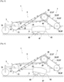
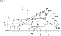
- FIG. 1 schematically illustrates an example of machine 1 with a turning system and a soil treatment system according to the invention.
- the machine 1 self-propelled or towed, comprises a turning system 2 with, successively, from front to rear, picking-up means 3, turning-up means 5, and spreading-up means 7.
- the picking-up means 3 make it possible to collect from the ground 9 a continuous sheet 11 of stems constituting the windrow.
- the turning-up means 5 are capable of turning said continuous sheet 11 on itself, the latter performing a half-spiral from its collection at the front of the picking-up means to the rear of said picking-up means.
- the spreading-up means 7 are capable of spreading the turned-up continuous sheet 11' on the ground 9. All of these picking-up, turning-up and spreading-up operations are carried out continuously while the machine is moving.
- the pick-up means 3 comprise a pick-up 13 provided with metal fingers 15, which may or may not be retractable.
- the pick-up 13 rotates on itself in the direction of the arrow F' opposite to the direction of rotation of the wheels of the machine 1, so that that the metal fingers 15, coming into contact with the continuous sheet 11, lift the latter and drive it in rotation on the surface as shown in the figure 2 .
- the pick-up is preceded by a wheel 19 which, when the machine 1 is moving, comes to bear on the outer surface 21 of the continuous sheet 11.
- This wheel 19 is adjustable in height, and makes it possible to keep the distance between the pick-up 13 and the continuous sheet 11 constant regardless of the irregularities of the ground 9.
- the turning means 5 consist of a belt 23 provided with pins 25, which is stretched between a front cylinder 27 and a rear cylinder 29.
- the front cylinder 27 is associated with the pick-up 13 such that the sheet 11 picked up by the fingers 15 of the pick-up is driven onto the belt 23 by the pins 25.
- This belt 23 is crossed between the front cylinder 27 and the rear cylinder 29 such that the sheet describes a half-spiral between the two cylinders during its movement from front to rear. In doing so, the stems initially arranged at ground level on top of the sheet are found below it after turning and vice versa.
- the crossed belt has an active strand and a passive strand.
- the active strand is understood to mean the part of the crossed belt transporting the flax stems from the front cylinder 27 to the rear cylinder 29 of the turning means 5.
- the passive strand corresponds to the return of the crossed belt empty from the rear cylinder 29 to the front cylinder 27, the flax stems having been previously transferred to the spreading means 7.
- the turning means 5 comprise mechanical elements such as round irons (not shown) allowing the support of the sheet 11 during its turning, when it is no longer supported by the spiked belt.
- the lifted sheet 11 is rotated by the metal fingers 15 of the pick-up 13, are then transported and supported by the belt 23 until said sheet 11 turns over, the latter then being supported by the round irons, the belt 23 with spikes 25 only allowing the transport of said sheet 11 to the rear of the turning means 5.
- the spreading means 7 preferably comprise a set of two parallel belts 33, 33' provided with pins 35, 35'. Each belt 33, 33' is mounted taut between a front cylinder 37, 37' and a rear cylinder 39, 39'.
- the front cylinder 37, 37' is arranged on the same axis 41 as the rear cylinder 27 of the turning means 5.
- the rear cylinder 39, 39' is arranged close to the ground 9 so that the turned sheet 11', driven by the pins 35, 35' which penetrate into the sheet 11', is spread on the ground 9 as close as possible to it so as to avoid any disturbance.
- the spreading means 7 also comprise a mechanical element, in particular round irons or a plate (not shown) allowing the support of the turned sheet 11' during its transfer from the front cylinder 37, 37' to the rear cylinder 39, 39'.
- the machine 1 also comprises, according to the present invention, a soil treatment system 43 intended to treat the soil.
- the soil treatment system 43 can thus comprise weeding means 45 and/or soil compaction means 47.
- the soil treatment system 43 is mounted on the machine 1, between the pick-up means 3 and the spreading means 7, that is to say that the soil treatment system 43 is positioned on the machine 1 so as to be able to treat the soil at the moment when the windrow is lifted by the machine 1 to turn it.
- the soil treatment system 43 can be mounted on the machine 1, below the turning means 5, as illustrated in the figures.
- the soil treatment system 43 is advantageously configured to treat a width of soil 9 corresponding to the width of the windrow(s) lifted by the machine 1 during the turning step.
- the ground treatment system 43 may be mechanically connected to the pick-up 13, for example by a front end or by both ends.
- the mechanical connection between the ground treatment system 43 and the pick-up 13 then makes it possible to move the ground treatment system 43 vertically, simultaneously with the pick-up 13, in order to adapt to the surface roughness of the ground 9.
- the treatment system 43 may then always be at the same distance from the ground 9.
- the soil treatment system 43 can be mounted on the chassis of the machine 1, independently of the pick-up 13, so that it can be positioned vertically relative to the ground 9, independently of the vertical position of the pick-up 13.
- the machine 1 may comprise a lifting means (not shown), integral with the machine 1 or the pick-up 13 as the case may be, and on which the soil treatment system 43 is mounted.
- the lifting means may thus be configured to raise or lower the treatment system 43 relative to the soil 9, to enable it to work the soil or not.
- the lifting means can make it possible to position the soil treatment system 43 on the ground 9 to allow it to work, or on the contrary to lift the soil treatment device 43 above the ground 9 when it is not necessary to use it, so as to limit the energy consumption of the machine 1, and limit, where appropriate, the raising of dust during the turning of the windrows.
- the inclination of the soil treatment system 43 can allow certain treatment means to be used, and not others, depending on the situations.
- the control of the lifting means, and possibly the tilting means, of the soil treatment system 43 can in particular be done from the control cabin of the machine 1, in order to implement them at the same time as the weeding means 45 or the compaction means 47 of the soil treatment device 43.
- the soil treatment system 43 may include weeding means, for example mechanical and/or chemical and/or electrical and/or thermal.
- the weeding means 45 may be mechanical, and include, but are not limited to: fixed towed means, such as plows or Canadian plows, for which the tool remains fixed relative to the support; means rotating towed implements for which the tool is mounted to rotate about a substantially horizontal axis so as to roll on the ground when the machine is moving, in order to limit the resistance to the advancement of the latter; and/or rotating powered means, such as rotary harrows, driven in rotation about a substantially vertical axis and capable of contributing to the advancement of the machine 1.
- fixed towed means such as plows or Canadian plows
- rotating towed implements for which the tool is mounted to rotate about a substantially horizontal axis so as to roll on the ground when the machine is moving, in order to limit the resistance to the advancement of the latter
- rotating powered means such as rotary harrows, driven in rotation about a substantially vertical axis and capable of contributing to the advancement of the machine 1.
- Such mechanical weeding methods can be used continuously, in particular, to systematically treat the soil when turning the windrow.
- the weeding means 45 may also comprise chemical means, for example nozzles for spraying a chemical product such as a weedkiller.
- chemical weeding means may in particular allow a localized action, in the case of a nozzle with limited projection, or a global action, in the case of a nozzle with extended projection or in the case of a plurality of nozzles.
- Such chemical weeding means may in particular allow a localized treatment of the soil, only in the places presenting weeds to be treated, in order to limit the consumption of the weedkiller.
- weeding means 45 are also conceivable, such as thermal weeding means, or even electric weeding means, whether punctually, to treat only the areas requiring such treatment, or on the contrary to systematically treat the ground, when the windrow is no longer placed on it.
- the latter may comprise means of detection (not shown), on the surface of the soil, of the plants to be treated.
- detection means may for example example include image acquisition means, such as one or more cameras, in particular thermal cameras, and analysis means configured to analyze the images provided by the image acquisition means.
- the analysis means may for example be based on artificial intelligence in order to identify, on the images provided by the image acquisition means, the plants or areas to be treated, and possibly the type of treatment to be carried out.
- the detection means can be configured to identify and recognize the different types of plants likely to be present under the windrows, and to determine which ones to treat and how.
- the detection means can also be configured to control the weeding means 45 when plants to be treated are detected.
- Such detection and recognition of plants therefore makes it possible to concentrate the weeding resources of the machine 1 only at the locations of the soil 9 where this is necessary, so as not to over-treat the soil and not to over-consume energy or weedkiller.
- the soil treatment system 43 may also comprise treatment means other than those for weeding, such as soil compaction means 47.
- the compaction means 47 may for example comprise a compaction roller mounted to pivot about a horizontal axis perpendicular to the direction of movement of the machine 1, so as to roll over the soil and flatten it by compaction or by crushing clods or other elements present on the surface of the soil 9.
- the soil compaction means 47 are mounted downstream, in the direction of movement of the machine 1, of the weeding means. The compaction means 47 therefore make it possible to improve the surface of the soil before redepositing the returned windrow 11' there, and in particular to re-flatten the soil 9 if the surface thereof has been deformed by weeding means 45, in particular mechanical ones.
- the detection means can be used to activate the soil compaction means 47 in a punctual and localized manner, so as not to create constant additional resistance to the advancement of the machine 1.
- a protective means for example a cover 49, is mounted above and around the weeding means 45 and the compacting means 47.
- the cover 49 then makes it possible to confine the particles and dust raised during the treatment of the soil 9, at the level of the soil treatment system 43.
- the cover 49 in particular limits the attachment of dust to the windrow during turning.
- the detection means described above are mounted outside said means of protection, for example above, in front of, or directly on the machine 1, at a distance from the means of protection, so as not to alter their operation.
- the machine according to the present invention it becomes easy and efficient to treat the soil on which windrows rest, by acting at the time of lifting the windrow(s) with a view to turning them over.
- the treatments carried out can be localized and punctual, or on the contrary generalized, without this causing damage to the windrows, which are above the soil treatment means at the time of their action, nor additional working time, since the treatment is carried out simultaneously with the turning of the windrow.
Landscapes
- Life Sciences & Earth Sciences (AREA)
- Environmental Sciences (AREA)
- Soil Working Implements (AREA)
- Processing Of Solid Wastes (AREA)
Claims (14)
- Maschine (1), motorgetrieben oder geschleppt, umfassend ein System zum Rückführen (2) von Pflanzenstängeln, z. B. mindestens einer Schwade (11), wobei das System zum Rückführen (2) Folgendes umfasst:- Mittel zum Sammeln (3), die konfiguriert sind, um die Pflanzenstängel auf dem Boden (9) in Form einem endlosen Schicht (11) aufzunehmen,- Mittel zum Rückführen (5), die konfiguriert sind, um die gesammelte Schicht (11) auf sich selbst rückzuführen, und- Mittel zum Ausbreiten (7), die konfiguriert sind, um die rückgeführte Schicht (11') auf dem Boden auszubreiten,wobei die Vorgänge auf endlose Weise während der Fortbewegung der Maschine (1) durchgeführt werden,dadurch gekennzeichnet, dass die Maschine (1) außerdem ein System zur Behandlung des Bodens (43) umfasst, das konfiguriert ist, um den Boden (9) zu behandeln und/oder Pflanzen zu behandeln, z. B. Unkraut zu jäten, und dadurch, dass das System zur Behandlung des Bodens (43) konfiguriert ist, um Pflanzen und/oder den Boden nach dem Aufnehmen der Pflanzenstängel durch die Mittel zum Sammeln (3) und vor dem Ausbreiten der Pflanzenstängel durch das System zum Rückführen (2) zu behandeln.
- Maschine (1) nach Anspruch 1, wobei das System zur Behandlung des Bodens (43) zwischen den Mitteln zum Sammeln (3) und den Mitteln zum Ausbreiten (7) des Systems zum Rückführen (2) montiert ist.
- Maschine (1) nach Anspruch 1 oder 2, wobei das System zur Behandlung des Bodens (43) unter Mitteln zum Rückführen (5) des Systems zum Rückführen (2) positioniert ist.
- Maschine (1) nach einem der vorhergehenden Ansprüche, wobei das System zur Behandlung des Bodens (43) Mittel zum Unkraut jäten (45) umfasst, z. B. mechanische und/oder chemische und/oder elektrische und/oder thermische Mittel.
- Maschine (1) nach dem vorhergehenden Anspruch, wobei die Mittel zum Unkraut jäten (43) mechanische Mittel sind, z. B.: fest, drehend um eine horizontale Querachse in der Fortbewegungsrichtung der Maschine oder drehend um eine vertikale Achse.
- Maschine (1) nach einem der vorhergehenden Ansprüche, wobei das System zur Behandlung des Bodens (43) auch Mittel zum Nachweis, auf der Oberfläche des Bodens, von zu behandelnden Pflanzen umfasst.
- Maschine (1) nach dem vorhergehenden Anspruch, wobei die Mittel zum Nachweis Folgendes umfassen: Mittel zur Aufnahme von Bildern, z. B. eine oder mehrere Kameras, insbesondere thermische Kameras, und Mittel zur Analyse, die konfiguriert sind, um die von den Mitteln zur Aufnahme von Bildern gelieferten Bilder zu analysieren, wobei die Mittel zur Analyse z. B. auf künstlicher Intelligenz basieren.
- Maschine (1) nach Anspruch 6 oder 7 in Kombination mit Anspruch 4, wobei die Mittel zum Nachweis auch konfiguriert sind, um die Mittel zum Unkraut jäten (45) zu steuern, wenn zu behandelnde Pflanzen nachgewiesen werden.
- Maschine (1) nach einem der vorhergehenden Ansprüche, wobei das System zur Behandlung des Bodens (43) Mittel zur Bodenverdichtung (47) umfasst, z. B. eine Walze.
- Maschine (1) nach einem der vorhergehenden Ansprüche, wobei das System zur Behandlung des Bodens (43) Mittel zum Unkraut jäten (45) und Mittel zur Bodenverdichtung (47) umfasst, und wobei die Mittel zur Bodenverdichtung (47) nachgelagert in der Fortbewegungsrichtung der Maschine (1) von den Mitteln zum Unkraut jäten (45) montiert sind.
- Maschine (1) nach einem der vorhergehenden Ansprüche, wobei das System zur Behandlung des Bodens (43) auch ein Schutzmittel umfasst, das konfiguriert ist, um einen Schutz zwischen dem System zur Behandlung des Bodens (43) und der Schicht von Pflanzenstengeln zu bilden, insbesondere der gesammelten Schicht (11).
- Maschine (1) nach einem der vorhergehenden Ansprüche, wobei das Schutzmittel eine Haube (49) umfasst, die über dem System zur Behandlung des Bodens (43) angeordnet ist.
- Maschine (1) nach einem der vorhergehenden Ansprüche, umfassend außerdem eine Steuerkabine und eine Steuervorrichtung, wobei die Steuervorrichtung konfiguriert ist, um das System zur Behandlung (43) von der Steuerkabine aus zu steuern.
- Maschine (1) nach einem der vorhergehenden Ansprüche, umfassend außerdem ein Hebemittel, wobei das Hebemittel auf der Maschine (1) montiert und konfiguriert ist, um das System zur Behandlung (43) mit Bezug auf den Boden (9) anzuheben oder abzusenken.
Applications Claiming Priority (1)
| Application Number | Priority Date | Filing Date | Title |
|---|---|---|---|
| FR2204202A FR3135186B1 (fr) | 2022-05-03 | 2022-05-03 | Engin comportant un système de retournage de tiges végétales |
Publications (3)
| Publication Number | Publication Date |
|---|---|
| EP4272539A1 EP4272539A1 (de) | 2023-11-08 |
| EP4272539C0 EP4272539C0 (de) | 2025-01-01 |
| EP4272539B1 true EP4272539B1 (de) | 2025-01-01 |
Family
ID=82019549
Family Applications (1)
| Application Number | Title | Priority Date | Filing Date |
|---|---|---|---|
| EP23169003.3A Active EP4272539B1 (de) | 2022-05-03 | 2023-04-20 | Maschine mit einem system zum rückführen von pflanzenstangen |
Country Status (2)
| Country | Link |
|---|---|
| EP (1) | EP4272539B1 (de) |
| FR (1) | FR3135186B1 (de) |
Family Cites Families (7)
| Publication number | Priority date | Publication date | Assignee | Title |
|---|---|---|---|---|
| FR2484768A1 (fr) | 1980-06-23 | 1981-12-24 | Neufville Charles | Dispositif de ramassage, retournage, etalage de lin |
| FR2916604B1 (fr) * | 2007-05-31 | 2009-09-04 | Depoortere Nv | Structure porteuse pour retourneuse d'andains |
| CN106612935A (zh) * | 2017-01-12 | 2017-05-10 | 张东升 | 自走式玉米收获、秸秆打捆与整地联合作业机 |
| CN107114053A (zh) * | 2017-06-21 | 2017-09-01 | 马鞍山英维爱生态科技有限公司 | 一种搅拌式根茬粉碎还田装置 |
| BE1028420B1 (nl) * | 2020-06-22 | 2022-01-31 | Hyler BV | Vezelplantverwerkingsmachine |
| BE1028410B1 (nl) * | 2020-06-22 | 2022-05-09 | Hyler BV | Vezelplantverwerkingsmachine |
| CN111887013A (zh) * | 2020-08-26 | 2020-11-06 | 朱建华 | 一种智能农业机械玉米秸秆处理一体化收割机 |
-
2022
- 2022-05-03 FR FR2204202A patent/FR3135186B1/fr active Active
-
2023
- 2023-04-20 EP EP23169003.3A patent/EP4272539B1/de active Active
Also Published As
| Publication number | Publication date |
|---|---|
| EP4272539C0 (de) | 2025-01-01 |
| FR3135186B1 (fr) | 2024-05-03 |
| FR3135186A1 (fr) | 2023-11-10 |
| EP4272539A1 (de) | 2023-11-08 |
Similar Documents
| Publication | Publication Date | Title |
|---|---|---|
| EP3071012B1 (de) | Verfahren und vorrichtung zum ausfahren und einziehen einer plane zum sammeln von kleinen früchten und erntemaschinen | |
| FR2962297A1 (fr) | Recolteuse agricole equipee d'un systeme ameliore d'adaptation au sol | |
| EP4298889A1 (de) | Maschine zur behandlung von mindestens einem schwaden | |
| EP1194031B1 (de) | Vorrichtung und verfahren zur bodenbelüftung mit abfallsammlung | |
| EP1976367B1 (de) | Bodenbearbeitungsmaschine in der art eines vertikalscheibenpfluges | |
| EP2720528B1 (de) | Maschine zum automatischen ziehen von abgeschnittenen weinreben | |
| CA2072652A1 (fr) | Machine pour ramasser, nettoyer et emballer les baches plastiques agricoles | |
| FR2916604A1 (fr) | Structure porteuse pour retourneuse d'andains | |
| EP4272539B1 (de) | Maschine mit einem system zum rückführen von pflanzenstangen | |
| EP0560655B1 (de) | Verfahren und Maschine zum Pflegen einer Rasenfläche wie einer Pferderennbahn oder Pferdetrainingsbahn | |
| FR2916603A1 (fr) | Engin de retournage d'andain | |
| JP4622455B2 (ja) | 作物体引抜き機 | |
| EP0842597B1 (de) | Überziehen von gepresstem Gut mit einer Schlauchfolie | |
| FR3111513A1 (fr) | Machine agricole comportant au moins un dispositif de traitement des végétaux et/ou du sol | |
| EP4552469A1 (de) | Vorrichtung zum bewegen eines schwades auf dem boden | |
| FR2688376A1 (fr) | Rouleau de travail du sol et machine le comportant. | |
| EP1095559A1 (de) | Spargelzuchtverfahren und Vorrichtung für den Einsatz einer Folie in diesem Verfahren | |
| EP0093683B1 (de) | Landwirtschaftliche Maschinen zum Umsetzen von Viehfutter oder anderen auf dem Boden liegenden Pflanzen | |
| FR2967864A1 (fr) | Charrue semi-portee avec un organe de nettoyage de roue perfectionne | |
| FR2501958A1 (fr) | Machine pour l'arrachage et le chargement de betteraves | |
| FR2792163A1 (fr) | Perfectionnement aux faucheuses munies de moyens qui permettent le transfert lateral des andains de fourrage | |
| FR2688526A1 (fr) | Dispositif de damage et machine de travail du sol le comportant. | |
| FR2695895A1 (fr) | Dispositif pour éviter l'embourbement des roues jumelées d'un engin. | |
| EP0408417B1 (de) | Klassierungs- und Einschliessungsvorrichtung für von einem Traktor gezogenen Stein-Schwadformer, der zwei in bezug auf die Fahrtrichtung des Traktors im "V" ausgebreitete Schenkel besitzt, die ausserdem nachgiebige und schwingungsfähige Zahnungen tragen | |
| EP4415509A1 (de) | Vorrichtung und verfahren zur mechanischen pflege eines rasens zur begrenzung des wachstums von unkraut |
Legal Events
| Date | Code | Title | Description |
|---|---|---|---|
| PUAI | Public reference made under article 153(3) epc to a published international application that has entered the european phase |
Free format text: ORIGINAL CODE: 0009012 |
|
| STAA | Information on the status of an ep patent application or granted ep patent |
Free format text: STATUS: THE APPLICATION HAS BEEN PUBLISHED |
|
| AK | Designated contracting states |
Kind code of ref document: A1 Designated state(s): AL AT BE BG CH CY CZ DE DK EE ES FI FR GB GR HR HU IE IS IT LI LT LU LV MC ME MK MT NL NO PL PT RO RS SE SI SK SM TR |
|
| STAA | Information on the status of an ep patent application or granted ep patent |
Free format text: STATUS: REQUEST FOR EXAMINATION WAS MADE |
|
| 17P | Request for examination filed |
Effective date: 20240327 |
|
| RBV | Designated contracting states (corrected) |
Designated state(s): AL AT BE BG CH CY CZ DE DK EE ES FI FR GB GR HR HU IE IS IT LI LT LU LV MC ME MK MT NL NO PL PT RO RS SE SI SK SM TR |
|
| GRAP | Despatch of communication of intention to grant a patent |
Free format text: ORIGINAL CODE: EPIDOSNIGR1 |
|
| STAA | Information on the status of an ep patent application or granted ep patent |
Free format text: STATUS: GRANT OF PATENT IS INTENDED |
|
| INTG | Intention to grant announced |
Effective date: 20240826 |
|
| GRAS | Grant fee paid |
Free format text: ORIGINAL CODE: EPIDOSNIGR3 |
|
| GRAA | (expected) grant |
Free format text: ORIGINAL CODE: 0009210 |
|
| STAA | Information on the status of an ep patent application or granted ep patent |
Free format text: STATUS: THE PATENT HAS BEEN GRANTED |
|
| AK | Designated contracting states |
Kind code of ref document: B1 Designated state(s): AL AT BE BG CH CY CZ DE DK EE ES FI FR GB GR HR HU IE IS IT LI LT LU LV MC ME MK MT NL NO PL PT RO RS SE SI SK SM TR |
|
| REG | Reference to a national code |
Ref country code: GB Ref legal event code: FG4D Free format text: NOT ENGLISH |
|
| REG | Reference to a national code |
Ref country code: CH Ref legal event code: EP |
|
| REG | Reference to a national code |
Ref country code: DE Ref legal event code: R096 Ref document number: 602023001554 Country of ref document: DE |
|
| REG | Reference to a national code |
Ref country code: IE Ref legal event code: FG4D Free format text: LANGUAGE OF EP DOCUMENT: FRENCH |
|
| U01 | Request for unitary effect filed |
Effective date: 20250127 |
|
| U07 | Unitary effect registered |
Designated state(s): AT BE BG DE DK EE FI FR IT LT LU LV MT NL PT RO SE SI Effective date: 20250131 |
|
| U20 | Renewal fee for the european patent with unitary effect paid |
Year of fee payment: 3 Effective date: 20250305 |
|
| PG25 | Lapsed in a contracting state [announced via postgrant information from national office to epo] |
Ref country code: PL Free format text: LAPSE BECAUSE OF FAILURE TO SUBMIT A TRANSLATION OF THE DESCRIPTION OR TO PAY THE FEE WITHIN THE PRESCRIBED TIME-LIMIT Effective date: 20250101 |
|
| PG25 | Lapsed in a contracting state [announced via postgrant information from national office to epo] |
Ref country code: ES Free format text: LAPSE BECAUSE OF FAILURE TO SUBMIT A TRANSLATION OF THE DESCRIPTION OR TO PAY THE FEE WITHIN THE PRESCRIBED TIME-LIMIT Effective date: 20250101 |
|
| PG25 | Lapsed in a contracting state [announced via postgrant information from national office to epo] |
Ref country code: NO Free format text: LAPSE BECAUSE OF FAILURE TO SUBMIT A TRANSLATION OF THE DESCRIPTION OR TO PAY THE FEE WITHIN THE PRESCRIBED TIME-LIMIT Effective date: 20250401 Ref country code: IS Free format text: LAPSE BECAUSE OF FAILURE TO SUBMIT A TRANSLATION OF THE DESCRIPTION OR TO PAY THE FEE WITHIN THE PRESCRIBED TIME-LIMIT Effective date: 20250501 |
|
| PG25 | Lapsed in a contracting state [announced via postgrant information from national office to epo] |
Ref country code: HR Free format text: LAPSE BECAUSE OF FAILURE TO SUBMIT A TRANSLATION OF THE DESCRIPTION OR TO PAY THE FEE WITHIN THE PRESCRIBED TIME-LIMIT Effective date: 20250101 |
|
| PG25 | Lapsed in a contracting state [announced via postgrant information from national office to epo] |
Ref country code: GR Free format text: LAPSE BECAUSE OF FAILURE TO SUBMIT A TRANSLATION OF THE DESCRIPTION OR TO PAY THE FEE WITHIN THE PRESCRIBED TIME-LIMIT Effective date: 20250402 |
|
| PG25 | Lapsed in a contracting state [announced via postgrant information from national office to epo] |
Ref country code: CZ Free format text: LAPSE BECAUSE OF FAILURE TO SUBMIT A TRANSLATION OF THE DESCRIPTION OR TO PAY THE FEE WITHIN THE PRESCRIBED TIME-LIMIT Effective date: 20250101 |
|
| PG25 | Lapsed in a contracting state [announced via postgrant information from national office to epo] |
Ref country code: SM Free format text: LAPSE BECAUSE OF FAILURE TO SUBMIT A TRANSLATION OF THE DESCRIPTION OR TO PAY THE FEE WITHIN THE PRESCRIBED TIME-LIMIT Effective date: 20250101 |
|
| PG25 | Lapsed in a contracting state [announced via postgrant information from national office to epo] |
Ref country code: SK Free format text: LAPSE BECAUSE OF FAILURE TO SUBMIT A TRANSLATION OF THE DESCRIPTION OR TO PAY THE FEE WITHIN THE PRESCRIBED TIME-LIMIT Effective date: 20250101 |
|
| PLBE | No opposition filed within time limit |
Free format text: ORIGINAL CODE: 0009261 |
|
| STAA | Information on the status of an ep patent application or granted ep patent |
Free format text: STATUS: NO OPPOSITION FILED WITHIN TIME LIMIT |
|
| 26N | No opposition filed |
Effective date: 20251002 |
|
| PG25 | Lapsed in a contracting state [announced via postgrant information from national office to epo] |
Ref country code: MC Free format text: LAPSE BECAUSE OF FAILURE TO SUBMIT A TRANSLATION OF THE DESCRIPTION OR TO PAY THE FEE WITHIN THE PRESCRIBED TIME-LIMIT Effective date: 20250101 |
|
| U20 | Renewal fee for the european patent with unitary effect paid |
Year of fee payment: 4 Effective date: 20260219 |