EP4270902A1 - Datenumwandlungsverfahren und -vorrichtung sowie speichermedium und elektronische vorrichtung - Google Patents
Datenumwandlungsverfahren und -vorrichtung sowie speichermedium und elektronische vorrichtung Download PDFInfo
- Publication number
- EP4270902A1 EP4270902A1 EP21913246.1A EP21913246A EP4270902A1 EP 4270902 A1 EP4270902 A1 EP 4270902A1 EP 21913246 A EP21913246 A EP 21913246A EP 4270902 A1 EP4270902 A1 EP 4270902A1
- Authority
- EP
- European Patent Office
- Prior art keywords
- data
- sample data
- link
- shift register
- layer transmission
- Prior art date
- Legal status (The legal status is an assumption and is not a legal conclusion. Google has not performed a legal analysis and makes no representation as to the accuracy of the status listed.)
- Granted
Links
Images


Classifications
-
- G—PHYSICS
- G06—COMPUTING OR CALCULATING; COUNTING
- G06F—ELECTRIC DIGITAL DATA PROCESSING
- G06F13/00—Interconnection of, or transfer of information or other signals between, memories, input/output devices or central processing units
- G06F13/38—Information transfer, e.g. on bus
- G06F13/40—Bus structure
- G06F13/4004—Coupling between buses
- G06F13/4009—Coupling between buses with data restructuring
- G06F13/4013—Coupling between buses with data restructuring with data re-ordering, e.g. Endian conversion
-
- G—PHYSICS
- G06—COMPUTING OR CALCULATING; COUNTING
- G06F—ELECTRIC DIGITAL DATA PROCESSING
- G06F13/00—Interconnection of, or transfer of information or other signals between, memories, input/output devices or central processing units
- G06F13/38—Information transfer, e.g. on bus
- G06F13/40—Bus structure
- G06F13/4004—Coupling between buses
- G06F13/4009—Coupling between buses with data restructuring
- G06F13/4018—Coupling between buses with data restructuring with data-width conversion
-
- G—PHYSICS
- G06—COMPUTING OR CALCULATING; COUNTING
- G06F—ELECTRIC DIGITAL DATA PROCESSING
- G06F13/00—Interconnection of, or transfer of information or other signals between, memories, input/output devices or central processing units
- G06F13/38—Information transfer, e.g. on bus
- G06F13/40—Bus structure
- G06F13/4004—Coupling between buses
- G06F13/4027—Coupling between buses using bus bridges
- G06F13/405—Coupling between buses using bus bridges where the bridge performs a synchronising function
- G06F13/4059—Coupling between buses using bus bridges where the bridge performs a synchronising function where the synchronisation uses buffers, e.g. for speed matching between buses
-
- G—PHYSICS
- G06—COMPUTING OR CALCULATING; COUNTING
- G06F—ELECTRIC DIGITAL DATA PROCESSING
- G06F13/00—Interconnection of, or transfer of information or other signals between, memories, input/output devices or central processing units
- G06F13/14—Handling requests for interconnection or transfer
- G06F13/16—Handling requests for interconnection or transfer for access to memory bus
- G06F13/1668—Details of memory controller
- G06F13/1689—Synchronisation and timing concerns
-
- G—PHYSICS
- G06—COMPUTING OR CALCULATING; COUNTING
- G06F—ELECTRIC DIGITAL DATA PROCESSING
- G06F13/00—Interconnection of, or transfer of information or other signals between, memories, input/output devices or central processing units
- G06F13/38—Information transfer, e.g. on bus
- G06F13/40—Bus structure
- G06F13/4004—Coupling between buses
- G06F13/4027—Coupling between buses using bus bridges
- G06F13/405—Coupling between buses using bus bridges where the bridge performs a synchronising function
Definitions
- Implementations of the present disclosure relate to the field of communications, and in particular, to a data conversion method and apparatus, a storage medium, and an electronic apparatus.
- sample data and link-layer transmission data of JESD204C need to be respectively acquired according to specific requirements of the protocol.
- the above method needs to separately acquire the sample data and the link-layer transmission data.
- the present disclosure proposes a conversion method for the sample data and the link-layer transmission data, so as to realize conversion between the sample data and the link-layer transmission data.
- the present disclosure provides a data conversion method and apparatus, a storage medium, and an electronic apparatus, so as to at least solving the problem of low acquisition efficiency of sample data and link-layer transmission data in the existing technology.
- An implementation of the present disclosure provides a data conversion method, including: acquiring sample data obtained by sampling in a network communication process; reordering the sample data; and performing a cross-clock operation and a bit-width conversion operation on the reordered sample data to obtain link-layer transmission data after conversion.
- Another implementation of the present disclosure provides a data conversion method, including: acquiring link-layer transmission data to be converted in a network communication process; performing a bit-width conversion operation and a cross-clock operation on the link-layer transmission data to obtain the processed link-layer transmission data; and determining data obtained after reordering the processed link-layer transmission data as sample data.
- Still another implementation of the present disclosure provides a data conversion apparatus, including: an acquisition unit configured to acquire sample data obtained by sampling in a network communication process; a reordering unit configured to reorder the sample data; and a processing unit configured to perform a cross-clock operation and a bit-width conversion operation on the reordered sample data to obtain link-layer transmission data after conversion.
- Yet another implementation of the present disclosure provides a data conversion apparatus, including: an acquisition unit configured to acquire link-layer transmission data to be converted in a network communication process; a processing unit configured to perform a bit-width conversion operation and a cross-clock operation on the link-layer transmission data to obtain the processed link-layer transmission data; and a reordering unit configured to determine data obtained after reordering the processed link-layer transmission data as sample data.
- Yet another implementation of the present disclosure further provides a computer-readable storage medium having a computer program stored therein, wherein the computer program is configured to implement, when being run, operations according to any one of the method implementations described above.
- Yet another implementation of the present disclosure further provides an electronic apparatus, including a memory having a computer program stored therein, and a processor configured to run the computer program to perform the operations according to any one of the method implementations described above.
- the data after the sample data or the link-layer transmission data is acquired, the data can be converted through the above methods, so that one of the sample data and the link-layer transmission data can be obtained by data conversion after the other one of the sample data and the link-layer transmission data is acquired.
- the need to separately acquire the sample data and the link-layer transmission data is obviated, and flexible conversion between the sample data and the link-layer transmission data is realized.
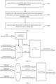
- FIG. 1 is a block diagram of a hardware structure of the mobile terminal where a data conversion method is performed according to an implementation of the present disclosure.
- the mobile terminal may include one or more processors 102 (merely one processor is shown in FIG.
- the processor 102 may include, but is not limited to, a processing device such as a microprocessor (e.g., a microcontroller unit (MCU)) or a programmable logic device (e.g., a field programmable gate array (FPGA))), and a memory 104 for storing data.
- the mobile terminal may further include a transmission device for a communication function and an input/output device 108.
- a processing device such as a microprocessor (e.g., a microcontroller unit (MCU)) or a programmable logic device (e.g., a field programmable gate array (FPGA))
- the mobile terminal may further include a transmission device for a communication function and an input/output device 108.
- FIG. 1 is merely for illustration and is not intended to limit the structure of the above mobile terminal.
- the mobile terminal may include more or fewer components than those shown in FIG. 1 , or may be configured in a way different from that shown in FIG. 1 .
- the memory 104 may be configured to store computer programs such as software programs and modules of application software, for example, the memory 104 is configured to store computer programs corresponding to the data conversion method provided by the implementation of the present disclosure. By executing the computer programs stored in the memory 104, the processor 102 performs various functional applications and data processing, that is, implementing the above data conversion method.
- the memory 104 may include a high-speed random access memory, and may also include a non-volatile memory, such as one or more magnetic storage devices, flash memories, or other non-volatile solid-state memories.
- the memory 104 may further include a memory remotely arranged relative to the processor 102, and the remote memory may be connected to the mobile terminal via a network. Examples of the above network include, but are not limited to, the Internet, an intranet, a local area network, a mobile communication network, and the combinations thereof.
- the transmission device 106 is configured to receive or transmit data via a network.
- the specific examples of the network may include a wireless network provided by a communication provider of the mobile terminal.
- the transmission device 106 includes a Network Interface Controller (NIC) that may be connected to other network devices via a base station so as to communicate with the Internet.
- the transmission device 106 may be a Radio Frequency (RF) module that is configured to communicate with the Internet in a wireless manner.
- NIC Network Interface Controller
- RF Radio Frequency
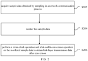
- FIG. 2 is a flowchart illustrating the data conversion method according to the implementation of the present disclosure.
- the method includes the following operations: operation S202, acquiring sample data obtained by sampling in a network communication process; operation S204, reordering the sample data; and operation S206, performing a cross-clock operation and a bit-width conversion operation on the reordered sample data to obtain link-layer transmission data after conversion.
- the data can be converted through the above operations of the method, so that one of the sample data and the link-layer transmission data can be obtained by data conversion after the other one of the sample data and the link-layer transmission data is acquired.
- An execution body of the above operations may be a base station, a terminal, etc., but the present disclosure is not limited thereto.
- reordering the sample data includes: selecting output data from multiple channels of sample data, writing the output data to a first memory module, and reading the output data from the first memory module according to an order to obtain the reordered sample data.
- selecting the output data from the multiple channels of sample data, writing the output data to the first memory module, and reading the output data from the first memory module according to the order to obtain the reordered sample data includes: selecting, by a multi-channel data selection module, the output data from the multiple channels of sample data according to selection configuration information in a first configuration information module, and writing, by the multi-channel data selection module, the selected output data to the first memory module according to write address information in the first configuration information module, with the data which needs to appear first on a lane written to a low address of the first memory module, and the data which needs to appear afterwards on the lane written to a high address of the first memory module; and acquiring the reordered sample data in ascending order of read addresses of the first memory module.
- performing the cross-clock operation on the reordered sample data includes: writing the sample data to a second memory module according to a first clock; and reading the sample data from the second memory module according to a second clock, with the first clock being different from the second clock.
- performing the bit-width conversion operation on the reordered sample data includes: acquiring a read enable parameter rd_en and a shift amount shift_num of a shift register, and storing the sample data of the second memory module in the shift register and performing a corresponding shift operation, according to rd_en and shift_num.
- the method before performing the cross-clock operation and the bit-width conversion operation on the reordered sample data, the method further includes: performing data frequency division and combination on the reordered sample data.
- Performing the cross-clock operation on the reordered sample data includes: performing the cross-clock operation on the sample data subjected to the data frequency division and combination.
- performing the data frequency division and combination on the reordered sample data includes: in the reordered sample data, in a case where n ⁇ N' is less than w, performing x-fold (or x-time) frequency division on the data having a bit width of n ⁇ N', and splicing the data involved in x beats of the shift register before and after the current operation (e.g., the current beat, e.g., the x beats including the current beat) of the shift register together to obtain data having a bit width of n ⁇ N' ⁇ x, where n denotes the number of the channels of the reordered sample data, N' denotes the transmission bit width of the reordered sample data, w denotes the bit width of the data transmitted on each lane, x denotes the frequency division multiplying factor, n ⁇ N' ⁇ x is greater than w, and n ⁇ N' ⁇ (x-1) is less than
- sample data and the link-layer transmission data are sample data and link-layer transmission data under JESD204C.
- an implementation provides a data conversion method. As shown in FIG. 3 , the method includes: operation S302, acquiring link-layer transmission data to be converted in a network communication process; operation S304, performing a bit-width conversion operation and a cross-clock operation on the link-layer transmission data to obtain the processed link-layer transmission data; and operation S306, determining data obtained after reordering the processed link-layer transmission data as sample data.
- performing the bit-width conversion operation on the link-layer transmission data includes: acquiring a write enable parameter wr_en and a shift amount shift_num of a shift register, using shift_num to control the shift register to operate, and writing output data of the shift register to a third memory module.
- performing the cross-clock operation on the link-layer transmission data includes: writing the link-layer transmission data to the third memory module according to a second clock; and reading the link-layer transmission data from the third memory module according to a first clock, with the first clock being different from the second clock.
- the method further includes: performing a frequency division and combination operation on the processed link-layer transmission data.
- Determining the data obtained by reordering the processed link-layer transmission data as the sample data includes: determining the data obtained by reordering the link-layer transmission data subjected to the frequency division and combination operation as the sample data.
- performing the frequency division and combination operation on the processed link-layer transmission data includes: in the processed link-layer transmission data, in a case where n ⁇ N' is less than w, performing x-fold frequency multiplication on the data having a bit width of n ⁇ N' ⁇ x to obtain output data having a bit width of n ⁇ N', with the data having the bit width of n ⁇ N' ⁇ x before the frequency multiplication and splitting being discontinuous, and the data having the bit width of n ⁇ N' after the splitting being continuous; and in a case where n ⁇ N' is greater than or equal to w, directly transmitting the processed link-layer transmission data in a pass-through manner, where n denotes the maximum number of the channels of the sample data transmitted on the lane, N' denotes the transmission bit width of the sample data after reordering, and x denotes the frequency division multiplying factor for performing the frequency division and combination on the link-layer transmission data.
- determining the data obtained by reordering the processed link-layer transmission data as the sample data includes: selecting output data from the processed link-layer transmission data, writing the output data to a fourth memory module, and reading the output data from the fourth memory module according to an order to obtain the sample data after reordering.
- selecting the output data from the processed link-layer transmission data, writing the output data to the fourth memory module, and reading the output data from the fourth memory module according to the order to obtain the sample data after reordering includes: selecting, by a multi-channel data selection module, the output data from the processed link-layer transmission data according to selection configuration information in a fourth configuration information module, and writing, by the multi-channel data selection module, the selected output data to the fourth memory module according to write address information in the fourth configuration information module, with the data which needs to appear first written to a low address of the fourth memory module, and the data which needs to appear afterwards written to a high address of the fourth memory module; and determining the reordered data as the sample data in ascending order of read addresses of the fourth memory module.
- sample data and the link-layer transmission data are sample data and link-layer transmission data under JESD204C.
- the input data described below may be the sample data and the output data described below may be the link-layer transmission data.
- the input data described below is the link-layer transmission data and the output data is the sample data.
- the data conversion methods provided by the implementations of the present disclosure are intended to achieve conversion from the sample data received by a JESD204C interface to the link-layer transmission data of the JESD204C interface and conversion from the link-layer transmission data of the JESD204C interface to the sample data sent by the JESD204C interface.
- the data conversion methods are applicable to a circuit design adopting the JESD204C high-speed interface technology, and are also applicable to a circuit design of the issued the protocols such as JESD204C.1 and JESD204USR.
- the implementations of the present disclosure realize conversion of related data of JESD204B, and overcome problems and defects of existing conversion methods for the related data of JESD204B that a circuit of a transport layer of JESD204B designed according to the existing conversion methods is large in area and power consumption and correct use by users is significantly affected due to the defects of complex circuit and inconvenient application of the existing conversion methods.
- the implementations of the present disclosure relate to complete content parameterization, and the re-ordering function and the bit-width conversion function for shifting related to the implementations of the present disclosure are performed according to the software configuration, so that the functions have good flexibility and universality.
- the whole circuit structure according to the implementations of the present disclosure is simple, and the bit-width conversion is performed using the shift register, so that hardware resources are reduced, and power consumption of the circuit is saved.
- the operations may be as follows: acquiring the sample data, and acquiring a channel associated clock of the sample data and a channel associated clock of data (the link-layer transmission data) to be output; reordering the sample data; performing the data frequency division and combination on the data output after the reordering; performing the cross-clock operation on the data; and performing the bit-width conversion on the data subjected to the cross-clock operation.
- the operations are as follows: acquiring a channel associated clock of the link-layer transmission data and a channel associated clock (a sampling clock) of the sample data to be output; performing the data bit-width conversion on the link-layer transmission data; performing the cross-clock operation on the data subjected to the bit-width conversion; and performing the frequency multiplication and splitting on the data output after the cross-clock operation, and reordering the split data to obtain the sample data.
- the above data conversion method may be implemented by a plurality of modules: a data reordering module configured to reorder the received sample data, which mainly includes adjusting a transmission order of the multiple channels of sample data according to requirements of the transport layer of the JESD204C interface; a data frequency division module mainly configured to perform the frequency division and combination on the data involved in two or more beats of the shift register before and after the current operation of the shift register in a scenario of the present disclosure where the bit width of the input data to be processed is less than that of the output data; a cross-clock module mainly configured to perform the cross-clock operation on the data; and a bit-width conversion module configured to perform the bit-width conversion on the data output after the cross-clock operation.
- a data reordering module configured to reorder the received sample data, which mainly includes adjusting a transmission order of the multiple channels of sample data according to requirements of the transport layer of the JESD204C interface
- a data frequency division module mainly configured to perform the frequency division and combination
- the above data conversion method may be implemented by a plurality of modules: a bit-width conversion module configured to perform the bit-width conversion on the link-layer transmission data output after the cross-clock operation; a cross-clock module mainly configured to perform the cross-clock operation on the link-layer transmission data; a data frequency multiplication module mainly configured to perform the frequency multiplication and splitting on the data output after the cross-clock operation in a scenario of the present disclosure where the bit width of the input data is greater than that of the output data; and a data reordering module mainly configured to reorder the data output by the data frequency multiplication module according to the requirements of the transport layer of the JESD204C interface, so as to meet a requirement for a transmission order of the sample data.
- a bit-width conversion module configured to perform the bit-width conversion on the link-layer transmission data output after the cross-clock operation
- a cross-clock module mainly configured to perform the cross-clock operation on the link-layer transmission data
- a data frequency multiplication module mainly
- the information which needs to be obtained in advance in the present disclosure includes: the maximum number M of data converters in a circuit and the maximum number L of transport lanes in the circuit.
- M and L do not refer to the maximum number of converters supported by a current device and the maximum number of transport lanes supported by the current device, but refer to a minimum size capable of embodying a rule of an operating cycle of the circuit.
- the maximum number of the converters supported by the current device is 64
- the maximum number of the channels of the sample data transmitted on one lane is n, and the maximum number of lanes on which one channel of sample data can be transmitted is k.
- the bit width of the data transmitted on each lane is denoted by w.
- the reordering module is instantiated for M times
- a data routing and frequency division module is instantiated for L times
- the cross-clock module is instantiated for L times
- the data bit-width conversion module is instantiated for L times.
- the operations of converting the sample data to the link-layer transmission data may be as follows: S1, performing a reordering function on the input sample data; S2, performing the data frequency division and combination on the newly ordered data as required; S3, performing the cross-clock operation on the data; and S4, performing the bit-width conversion on the data to obtain the link-layer transmission data.
- a corresponding hardware circuit for each channel of sample data includes a configuration information module, a multi-channel data selection module, and a memory module.
- the configuration information module stores configuration information
- the multi-channel data selection module is configured to select one channel of output data from multiple channels of output data
- the memory module performs a data storage function.
- the sample data are transmitted on a lane in a chronological order, and meanwhile, positions of the sample data may be interchanged at a same moment.
- a width of the memory is equal to the transmission bit width N' of the sample data
- a depth of the memory is twice of the desired maximum value of S
- an write operation on the memory is performed according to the configuration information
- a read operation on the memory is performed in ascending order of the read addresses.
- the sample data is input, and the newly ordered data, which is the reordered sample data, is output.
- M channels of newly ordered data output after the operation S1 are collectively routed to n channels of data, and the n channels of data are subjected to the frequency division processing, as shown in FIG. 5 .
- the number of the channels of sample data transmitted by one certain lane may be less than n in practical applications, so the sample data to be transmitted needs to be selected from the M channels of sample data, which is a static selection process.
- the frequency division processing of the n channels of data is performed in the following two cases.
- n ⁇ N' is less than w
- the data having the bit width of n ⁇ N' is subjected to the x-fold frequency division, and a value of x is configured through the software based on a principle that the minimum value of x that enables n ⁇ N'* x to be greater than w is configured as the value of x.
- the splicing operation is performed on the data involved in the x beats of the shift register before and after the current operation of the shift register according to a certain order (from a high position to a low position, or from a low position), the data output by the splicing operation has the bit width of n ⁇ N' ⁇ x , and meanwhile, a validity indication signal dv of output data is correspondingly sent out when the whole x-fold splicing operation is completed once, and the validity indication signal is set to "invalid" when the whole splicing operation is not completed.
- n ⁇ N' is greater than or equal to w
- the data is directly transmitted in a pass-through manner without being subjected to any processing, that is, it may be understood as that the data is subjected to 1-fold frequency division, and the corresponding validity indication signal is always set to "valid".
- the cross-clock function to transfer the frequency-divided data from the sampling clock to a link transmission clock is completed, as shown in FIG. 6 , and the cross-clock function is achieved through read and write control over the memory.
- the data bit width of the memory is n ⁇ N' ⁇ x .
- a corresponding hardware circuit for each lane includes: a configuration information module, a cross-clock module (as shown in operation 103), and a bit-width conversion module.
- the configuration information module stores information needed by the bit-width conversion and read enable information of the memory, the memory is configured to cache cross-clock data, and the bit-width conversion module performs the bit-width conversion according to the configuration information.
- the bit-width conversion module is implemented as the shift register herein, and a bit width of the shift register is n ⁇ N'* x + w .
- cnt cnt - w + n ⁇ N'*x .
- Two kinds of configuration information are used here: one for controlling the read enable parameter rd_en of the read operation of the memory, and the other for controlling the shift amount shift_num of the shift register. Based on the above principle, as long as the bit widths before and after the bit-width conversion are obtained, the two kinds of configuration information may be calculated. Therefore, the two kinds of configuration information are written to the configuration information module in advance. When the circuit starts to operate, the configuration information is read from the configuration information module, and the bit-width conversion is performed according to the configuration information.
- the operations of converting the link-layer transmission data to the sample data to may be as follows: S5, performing a reordering function on the input sample data; S6, performing the data frequency division and combination on the newly or ordered data as required; S7, performing the cross-clock operation on the data; and S8, performing the bit-width conversion on the data to obtain the link-layer transmission data.
- the information which needs to be obtained in advance in the present disclosure includes: the maximum number of channels of the sample data transmitted on one lane is n, and the maximum number of lanes on which one channel of sample data can be transmitted is l.
- the bit width of the data transmitted on each lane is defined as w.
- a corresponding hardware circuit for each lane includes: a configuration information module, a bit-width conversion module, and a cross-clock module.
- the configuration information module stores information needed by the bit-width conversion and write enable information of the memory, the memory is configured to cache cross-clock data, and the bit-width conversion module performs the bit-width conversion according to the configuration information.
- the bit-width conversion module is implemented as the shift register herein, and a bit width of the shift register is n ⁇ N'* x +w .
- An operating principle of the bit-width conversion module is as follows: when the circuit starts to operate, the input data having the bit width of w is continuously sent to the shift register, and meanwhile, the counter cnt is set to represent the data left in the shift register in the next beat of the shift register.
- Two kinds of configuration information are used here: one for controlling the write enable parameter wr_en of a write operation of the memory, and the other for controlling the shift amount shift_num of the shift register. Based on the above principle, as long as the bit widths before and after the bit-width conversion are obtained, the two kinds of configuration information may be calculated. Therefore, the two kinds of configuration information are written to the configuration information module in advance. When the circuit starts to operate, the configuration information is read from the configuration information module, and the bit-width conversion is performed according to the configuration information.
- the circuit performs the cross-clock function to transfer the frequency-divided data from the sampling clock to the link transmission clock, and the cross-clock function is achieved through read and write control over the memory.
- the data bit width of the memory is n ⁇ N' ⁇ x .
- the control over the read operation of the memory is related to the operation S7, at this time, a bit width for data reading is n ⁇ N' ⁇ x .
- the data reading may not be continuously performed, and may be performed when the corresponding signal dv is set to "valid", and the signal dv is generated based on a principle illustrated by FIG. 8 , and determines the data bit width in the operation S6. Meanwhile, the data output in the operation S6 is subjected to the frequency multiplication and splitting, which is performed in the following two cases.
- n ⁇ N' is less than w
- the data having the bit width of n ⁇ N' is subjected to the x-fold frequency division, and a value of x is configured through the software based on a principle that the minimum value of x that enables n ⁇ N' ⁇ x to be greater than w is configured as the value of x, at this time, the data bit width corresponding to operation 502 is n ⁇ N'* x , and the corresponding signal dv is set to "valid" every x sampling clocks.
- the data having the bit width of n ⁇ N'* x for one beat of the shift register is sequentially subjected to a splitting operation according to a certain order (from a high position to a low position, or from a low position), the data output by the splicing has the bit width of n ⁇ N' .
- the data having the bit width of n ⁇ N' ⁇ x before the frequency multiplication and splitting is discontinuous, and the data having the bit width of n ⁇ N' after the splitting is continuous.
- n ⁇ N' is greater than or equal to w
- the data is directly transmitted in a pass-through manner without being subjected to any processing, that is, it may be understood as that the data is subjected to 1-fold frequency multiplication, and the corresponding validity indication signal dv is always set to "valid".
- a corresponding hardware circuit for each channel of sample data includes a configuration information module, a multi-channel data selection module, and a memory module.
- the configuration information module stores configuration information
- the multi-channel data selection module is configured to select one channel of output data from multiple channels of output data
- the memory module performs a data storage function.
- the sample data are transmitted on a lane in a chronological order, and meanwhile, positions of the sample data may be interchanged at a same moment.
- a chronological order of the data output in the operation 503 needs to be adjusted, and positions of the data in a same beat of the shift register need to be adjusted for all lanes.
- the sample data to appear first in following processing is written to the low address of the memory, and the data to appear afterwards is written to the high address of the memory.
- contents of write data of each memory are derived from selective output of k ⁇ l channels of data. Write addresses of each memory and selection information of the write data are configured in advance through the software, and the circuit operates according to the configuration information.
- a width of the memory is equal to the transmission bit width N' of the sample data, a depth of the memory is twice of the desired maximum value of S, an write operation on the memory is performed according to the configuration information, and a read operation on the memory is performed in ascending order of the read addresses.
- two memory modules and two configuration information modules need to be used for converting the sample data to the link-layer transmission data
- two memory modules and two configuration information modules need to be used for converting the link-layer transmission data to the sample data.
- the four memory modules are different from each other, so are the four configuration information modules.
- the configuration information for converting the sample data to the link-layer transmission data is also different from that for converting the link-layer transmission data to the sample data.
- the methods according to the above implementations may be implemented by software together with a necessary general-purpose hardware platform, and may also be implemented by hardware, and the former is better in most cases.
- the technical solutions of the present disclosure or a part of the technical solutions of the present disclosure contributing to the existing technology may be implemented in the form of a software product, which is stored in a storage medium (such as a Read-Only Memory (ROM)/Random Access Memory (RAM), a magnetic disk and an optical disc) and includes several instructions to enable a terminal device (which may be a mobile phone, a computer, a server or a network device) to perform the methods described in the implementations of the present disclosure.
- a storage medium such as a Read-Only Memory (ROM)/Random Access Memory (RAM), a magnetic disk and an optical disc
- a terminal device which may be a mobile phone, a computer, a server or a network device
- An implementation of the present disclosure further provides a data conversion apparatus configured to implement the above implementations and preferred implementations, and what is described above will not be repeated below.
- module refers to software, hardware, or a combination of software and hardware that can perform predetermined functions.
- the apparatus described in the implementation below is better implemented by software, the implementations of the apparatus by hardware or a combination of software and hardware are possible and can be conceived.
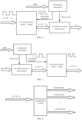
- FIG. 10 is a block diagram of the data conversion apparatus according to the implementation of the present disclosure.
- the apparatus includes: an acquisition unit 1002 configured to acquire sample data obtained by sampling in a network communication process; a reordering unit 1004 configured to reorder the sample data; and a processing unit 1006 configured to perform a cross-clock operation and a bit-width conversion operation on the reordered sample data to obtain link-layer transmission data after conversion.
- the reordering unit includes: a reordering module configured to use a configuration information module, a multi-channel data selection module, and a memory module to reorder the sample data.
- the reordering module includes: a reordering sub-module configured to select output data from multiple channels of sample data, write the output data to a first memory module, and read the output data from the first memory module according to an order to obtain the reordered sample data.
- the reordering sub-module is further configured to control the multi-channel data selection module to select the output data from the multiple channels of sample data according to selection configuration information in a first configuration information module and write the selected output data to the first memory module according to write address information in the first configuration information module, with the data which needs to appear first on a lane written to a low address of the first memory module, and the data which needs to appear afterwards on the lane written to a high address of the first memory module; and acquire the reordered sample data in ascending order of read addresses of the first memory module.
- the processing unit includes: a write module configured to write the sample data to a second memory module according to a first clock; and a read module configured to read the sample data from the second memory module according to a second clock, with the first clock being different from the second clock.
- the processing unit further includes: a processing module configured to acquire a read enable parameter rd_en and a shift amount shift_num of a shift register, store the sample data of the second memory module in the shift register according to rd_en and shift_num, and perform a corresponding shift operation.
- a processing module configured to acquire a read enable parameter rd_en and a shift amount shift_num of a shift register, store the sample data of the second memory module in the shift register according to rd_en and shift_num, and perform a corresponding shift operation.
- the apparatus further includes: a frequency division and combination unit configured to perform data frequency division and combination on the reordered sample data before the cross-clock operation and the bit-width conversion operation are performed on the reordered sample data.
- a frequency division and combination unit configured to perform data frequency division and combination on the reordered sample data before the cross-clock operation and the bit-width conversion operation are performed on the reordered sample data.
- the processing unit includes: a cross-clock module configured to perform the cross-clock operation on the sample data subjected to the data frequency division and combination.
- the frequency division and combination unit includes: a frequency division and combination module configured to perform the following operations: in the reordered sample data, in a case where n ⁇ N' is less than w, performing x-fold frequency division on the data having a bit width of n ⁇ N', and splicing the data involved in x beats of the shift register before and after the current operation of the shift register together to obtain data having a bit width of n ⁇ N' ⁇ x, where n denotes the number of the channels of the reordered sample data, N' denotes the transmission bit width of the reordered sample data, w denotes the bit width of the data transmitted on each lane, x denotes the frequency division multiplying factor, n ⁇ N' ⁇ x is greater than w, and n ⁇ N' ⁇ (x - 1) is less than w; and in the reordered sample data, in a case where n ⁇ N' is greater than w,
- FIG. 11 is a block diagram of another data conversion apparatus according to an implementation of the present disclosure.
- the apparatus includes: an acquisition unit 1102 configured to acquire link-layer transmission data to be converted in a network communication process; a processing unit 1104 configured to perform a bit-width conversion operation and a cross-clock operation on the link-layer transmission data to obtain the processed link-layer transmission data; and a reordering unit 1106 configured to determine data obtained after reordering the processed link-layer transmission data as sample data.
- the processing unit includes: a processing module configured to acquire a write enable parameter wr_en and a shift amount shift_num of a shift register, use shift_num to control the shift register to operate, and write output data of the shift register to a third memory module.
- the processing unit includes: a write module configured to write the link-layer transmission data to the third memory module according to a second clock; and a read module configured to read the link-layer transmission data from the third memory module according to a first clock, with the first clock being different from the second clock.
- the apparatus further includes: a frequency division and combination unit configured to perform, after the bit-width conversion operation and the cross-clock operation are performed on the link-layer transmission data, a frequency division and combination operation on the processed link-layer transmission data.
- the reordering unit includes: a determination module configured to determine the data obtained by reordering the link-layer transmission data subjected to the frequency division and combination operation as the sample data.
- the frequency division and combination unit includes: a frequency division and combination module configured to perform the following operations: in the processed link-layer transmission data, in a case where n ⁇ N' is less than w, performing x-fold frequency multiplication on the data having a bit width of n ⁇ N'* x to obtain output data having a bit width of n ⁇ N', with the data having the bit width of n ⁇ N'* x before the frequency multiplication and splitting being discontinuous, and the data having the bit width of n ⁇ N' after the splitting being continuous; and in a case where n ⁇ N' is greater than or equal to w, directly transmitting the processed link-layer transmission data in a pass-through manner, where n denotes the maximum number of the channels of the sample data transmitted on the lane, N' denotes the transmission bit width of the sample data after reordering, and x denotes the frequency division multiplying factor for performing the frequency division and combination on the link-layer transmission data.
- the reordering unit includes: a reordering module configured to select output data from the processed link-layer transmission data, write the output data to a fourth memory module, and read the output data from the fourth memory module according to an order to obtain the sample data after reordering.
- the reordering module is further configured to control a multi-channel data selection module to select the output data from the processed link-layer transmission data according to selection configuration information in a fourth configuration information module and write the selected output data to the fourth memory module according to write address information in the fourth configuration information module, with the data which needs to appear first written to a low address of the fourth memory module, and the data which needs to appear afterwards written to a high address of the fourth memory module; and determine the reordered data as the sample data in ascending order of read addresses of the fourth memory module.
- each of the above modules may be implemented by software or hardware.
- the modules may be implemented in following ways, but not limited to the following ways: all the modules are located in a same processor; or the modules are randomly combined and located in different processors.
- An implementation of the present disclosure further provides a computer-readable storage medium having a computer program stored therein, and the computer program is configured to perform, when being run, the operations according to any one of the method implementations described above.
- the computer-readable storage medium may include, but is not limited to: various media capable of storing a computer program, such as a USB flash disk, an ROM, an RAM, a mobile hard disk, a magnetic disk and an optical disc.
- An implementation of the present disclosure further provides an electronic apparatus, including a memory having a computer program stored therein, and a processor configured to run the computer program to perform the operations according to any one of the method implementations described above.
- the electronic apparatus may further include a transmission device connected to the processor, and an input/output device connected to the processor.
- modules or operations of the present disclosure described above may be implemented by a general-purpose computing device, may be integrated in a single computing device or distributed on a network composed of a plurality of computing devices, and may be implemented by program codes executable by a computing device, so that the modules or operations can be stored in a storage device and executed by the computing device. In some cases, the operations illustrated or described may be performed in an order different from that described herein. The modules or operations may be separately made into integrated circuit modules, or some of the modules or operations may be made into a single integrated circuit module. Thus, the present disclosure is not limited to any specific combination of hardware and software.
Landscapes
- Engineering & Computer Science (AREA)
- General Engineering & Computer Science (AREA)
- Theoretical Computer Science (AREA)
- Computer Hardware Design (AREA)
- Physics & Mathematics (AREA)
- General Physics & Mathematics (AREA)
- Communication Control (AREA)
- Synchronisation In Digital Transmission Systems (AREA)
Applications Claiming Priority (2)
| Application Number | Priority Date | Filing Date | Title |
|---|---|---|---|
| CN202011639456.4A CN114765628B (zh) | 2020-12-31 | 2020-12-31 | 数据转换方法和装置、存储介质及电子装置 |
| PCT/CN2021/119361 WO2022142501A1 (zh) | 2020-12-31 | 2021-09-18 | 数据转换方法和装置、存储介质及电子装置 |
Publications (4)
| Publication Number | Publication Date |
|---|---|
| EP4270902A1 true EP4270902A1 (de) | 2023-11-01 |
| EP4270902A4 EP4270902A4 (de) | 2024-06-19 |
| EP4270902B1 EP4270902B1 (de) | 2025-04-23 |
| EP4270902B9 EP4270902B9 (de) | 2025-08-20 |
Family
ID=82258988
Family Applications (1)
| Application Number | Title | Priority Date | Filing Date |
|---|---|---|---|
| EP21913246.1A Active EP4270902B9 (de) | 2020-12-31 | 2021-09-18 | Datenumwandlungsverfahren und -vorrichtung sowie speichermedium und elektronische vorrichtung |
Country Status (3)
| Country | Link |
|---|---|
| EP (1) | EP4270902B9 (de) |
| CN (1) | CN114765628B (de) |
| WO (1) | WO2022142501A1 (de) |
Families Citing this family (2)
| Publication number | Priority date | Publication date | Assignee | Title |
|---|---|---|---|---|
| CN115543882B (zh) * | 2022-11-30 | 2023-03-14 | 无锡沐创集成电路设计有限公司 | 不同位宽总线间的数据转发装置及数据传输方法 |
| CN115840724B (zh) * | 2023-02-09 | 2023-05-16 | 苏州浪潮智能科技有限公司 | 一种位宽转换电路及数据传输系统 |
Family Cites Families (8)
| Publication number | Priority date | Publication date | Assignee | Title |
|---|---|---|---|---|
| US20030002474A1 (en) * | 2001-03-21 | 2003-01-02 | Thomas Alexander | Multi-stream merge network for data width conversion and multiplexing |
| CN101166151B (zh) * | 2007-09-20 | 2010-07-14 | 北大方正集团有限公司 | 跨时钟域不同位宽数据传递的方法及装置 |
| US7642939B2 (en) * | 2008-05-15 | 2010-01-05 | Samplify Systems, Inc. | Configurations for data ports at digital interface for multiple data converters |
| CN104243083B (zh) * | 2013-06-07 | 2019-08-09 | 中兴通讯股份有限公司 | 一种数据映射方法、装置及电子设备 |
| CN103969500B (zh) * | 2014-04-11 | 2017-09-12 | 深圳市中电电力技术股份有限公司 | 智能电网模拟量采集装置、方法及系统 |
| CN106294234B (zh) * | 2016-08-01 | 2018-09-21 | 深圳云天励飞技术有限公司 | 一种数据传输方法及装置 |
| CN106933774B (zh) * | 2017-03-10 | 2019-08-27 | 重庆湃芯微电子有限公司 | 一种jesd204b协议中解帧的方法 |
| CN110221994B (zh) * | 2018-03-01 | 2022-04-08 | 深圳市中兴微电子技术有限公司 | 一种数据位宽转换的方法及装置、计算机可读存储介质 |
-
2020
- 2020-12-31 CN CN202011639456.4A patent/CN114765628B/zh active Active
-
2021
- 2021-09-18 EP EP21913246.1A patent/EP4270902B9/de active Active
- 2021-09-18 WO PCT/CN2021/119361 patent/WO2022142501A1/zh not_active Ceased
Also Published As
| Publication number | Publication date |
|---|---|
| EP4270902B1 (de) | 2025-04-23 |
| EP4270902A4 (de) | 2024-06-19 |
| WO2022142501A1 (zh) | 2022-07-07 |
| CN114765628B (zh) | 2024-08-27 |
| EP4270902B9 (de) | 2025-08-20 |
| CN114765628A (zh) | 2022-07-19 |
Similar Documents
| Publication | Publication Date | Title |
|---|---|---|
| US11864226B2 (en) | Method for configuring contention free random access resource, user equipment and network device | |
| US11246168B2 (en) | Method for random access and terminal device | |
| KR100703406B1 (ko) | Dma 제어 장치 및 방법 | |
| EP4270902A1 (de) | Datenumwandlungsverfahren und -vorrichtung sowie speichermedium und elektronische vorrichtung | |
| CN111786737B (zh) | 数据的发送方法、装置、存储介质以及电子装置 | |
| EP3582570A1 (de) | Verfahren zur anzeige der belegung eines dienstressourcenanzeigekanals, vorrichtung und speichermedium | |
| JP2022084661A (ja) | 同期方法および装置 | |
| US12185302B2 (en) | Feedback channel mapping method and apparatus, device, and storage medium | |
| CN101820700B (zh) | 一种基站的工作模式识别方法、装置及基站 | |
| CN110968538A (zh) | 一种数据缓冲方法和装置 | |
| CN116961696A (zh) | 一种双模模块通信方法、装置、电子设备及存储介质 | |
| CA3066923C (en) | Information transmission method, device, and system | |
| KR20230169304A (ko) | 표시 방법, 기준 신호 전송 방법, 통신 노드, 및 저장 매체 | |
| US10651997B2 (en) | Pilot signal configuration method and device | |
| KR101964755B1 (ko) | 모의기 연동을 위한 최적화된 시간-동기화 방법 및 시스템 | |
| EP3500009A1 (de) | Übertragungsressourcenanzeigeverfahren, vorrichtung und datenspeichermedium | |
| CN115629646A (zh) | 波形输出方法、装置、硬件设备及计算机可读存储介质 | |
| JP2007259274A (ja) | 再送制御回路、送信装置、再送制御方法及び再送制御プログラム | |
| CN110971378A (zh) | 数据传输方法和设备 | |
| EP4518222A1 (de) | Verfahren zur verarbeitung der überlappung von physikalischen uplink-steuerkanälen, endgerät und netzwerkseitige vorrichtung | |
| RU2819766C2 (ru) | Запоминающий носитель, оборудование, устройство и способ отображения каналов обратной связи | |
| JP5752063B2 (ja) | 信号発生装置、試験システムおよび信号発生方法 | |
| CN107547332B (zh) | 数据传输方法及装置 | |
| CN115225203A (zh) | 一种数据的解交织方法、装置、电子设备及存储介质 | |
| KR101005777B1 (ko) | 복수개의 채널로의 데이터 전송 방법 및 장치 |
Legal Events
| Date | Code | Title | Description |
|---|---|---|---|
| STAA | Information on the status of an ep patent application or granted ep patent |
Free format text: STATUS: THE INTERNATIONAL PUBLICATION HAS BEEN MADE |
|
| PUAI | Public reference made under article 153(3) epc to a published international application that has entered the european phase |
Free format text: ORIGINAL CODE: 0009012 |
|
| STAA | Information on the status of an ep patent application or granted ep patent |
Free format text: STATUS: REQUEST FOR EXAMINATION WAS MADE |
|
| 17P | Request for examination filed |
Effective date: 20230728 |
|
| AK | Designated contracting states |
Kind code of ref document: A1 Designated state(s): AL AT BE BG CH CY CZ DE DK EE ES FI FR GB GR HR HU IE IS IT LI LT LU LV MC MK MT NL NO PL PT RO RS SE SI SK SM TR |
|
| DAV | Request for validation of the european patent (deleted) | ||
| DAX | Request for extension of the european patent (deleted) | ||
| A4 | Supplementary search report drawn up and despatched |
Effective date: 20240516 |
|
| RIC1 | Information provided on ipc code assigned before grant |
Ipc: H03H 17/06 20060101ALI20240513BHEP Ipc: G06F 13/40 20060101ALI20240513BHEP Ipc: H04L 67/00 20220101AFI20240513BHEP |
|
| GRAP | Despatch of communication of intention to grant a patent |
Free format text: ORIGINAL CODE: EPIDOSNIGR1 |
|
| STAA | Information on the status of an ep patent application or granted ep patent |
Free format text: STATUS: GRANT OF PATENT IS INTENDED |
|
| INTG | Intention to grant announced |
Effective date: 20250207 |
|
| GRAS | Grant fee paid |
Free format text: ORIGINAL CODE: EPIDOSNIGR3 |
|
| GRAA | (expected) grant |
Free format text: ORIGINAL CODE: 0009210 |
|
| STAA | Information on the status of an ep patent application or granted ep patent |
Free format text: STATUS: THE PATENT HAS BEEN GRANTED |
|
| AK | Designated contracting states |
Kind code of ref document: B1 Designated state(s): AL AT BE BG CH CY CZ DE DK EE ES FI FR GB GR HR HU IE IS IT LI LT LU LV MC MK MT NL NO PL PT RO RS SE SI SK SM TR |
|
| REG | Reference to a national code |
Ref country code: GB Ref legal event code: FG4D |
|
| REG | Reference to a national code |
Ref country code: CH Ref legal event code: EP |
|
| REG | Reference to a national code |
Ref country code: DE Ref legal event code: R096 Ref document number: 602021029814 Country of ref document: DE |
|
| REG | Reference to a national code |
Ref country code: IE Ref legal event code: FG4D |
|
| REG | Reference to a national code |
Ref country code: CH Ref legal event code: PK Free format text: BERICHTIGUNG B9 |
|
| REG | Reference to a national code |
Ref country code: NL Ref legal event code: MP Effective date: 20250423 |
|
| PG25 | Lapsed in a contracting state [announced via postgrant information from national office to epo] |
Ref country code: NL Free format text: LAPSE BECAUSE OF FAILURE TO SUBMIT A TRANSLATION OF THE DESCRIPTION OR TO PAY THE FEE WITHIN THE PRESCRIBED TIME-LIMIT Effective date: 20250423 |
|
| REG | Reference to a national code |
Ref country code: AT Ref legal event code: MK05 Ref document number: 1788923 Country of ref document: AT Kind code of ref document: T Effective date: 20250423 |
|
| PG25 | Lapsed in a contracting state [announced via postgrant information from national office to epo] |
Ref country code: ES Free format text: LAPSE BECAUSE OF FAILURE TO SUBMIT A TRANSLATION OF THE DESCRIPTION OR TO PAY THE FEE WITHIN THE PRESCRIBED TIME-LIMIT Effective date: 20250423 Ref country code: FI Free format text: LAPSE BECAUSE OF FAILURE TO SUBMIT A TRANSLATION OF THE DESCRIPTION OR TO PAY THE FEE WITHIN THE PRESCRIBED TIME-LIMIT Effective date: 20250423 Ref country code: PT Free format text: LAPSE BECAUSE OF FAILURE TO SUBMIT A TRANSLATION OF THE DESCRIPTION OR TO PAY THE FEE WITHIN THE PRESCRIBED TIME-LIMIT Effective date: 20250825 |
|
| PGFP | Annual fee paid to national office [announced via postgrant information from national office to epo] |
Ref country code: DE Payment date: 20250722 Year of fee payment: 5 |
|
| REG | Reference to a national code |
Ref country code: LT Ref legal event code: MG9D |
|
| PG25 | Lapsed in a contracting state [announced via postgrant information from national office to epo] |
Ref country code: GR Free format text: LAPSE BECAUSE OF FAILURE TO SUBMIT A TRANSLATION OF THE DESCRIPTION OR TO PAY THE FEE WITHIN THE PRESCRIBED TIME-LIMIT Effective date: 20250724 Ref country code: NO Free format text: LAPSE BECAUSE OF FAILURE TO SUBMIT A TRANSLATION OF THE DESCRIPTION OR TO PAY THE FEE WITHIN THE PRESCRIBED TIME-LIMIT Effective date: 20250723 |
|
| PG25 | Lapsed in a contracting state [announced via postgrant information from national office to epo] |
Ref country code: PL Free format text: LAPSE BECAUSE OF FAILURE TO SUBMIT A TRANSLATION OF THE DESCRIPTION OR TO PAY THE FEE WITHIN THE PRESCRIBED TIME-LIMIT Effective date: 20250423 |
|
| PG25 | Lapsed in a contracting state [announced via postgrant information from national office to epo] |
Ref country code: BG Free format text: LAPSE BECAUSE OF FAILURE TO SUBMIT A TRANSLATION OF THE DESCRIPTION OR TO PAY THE FEE WITHIN THE PRESCRIBED TIME-LIMIT Effective date: 20250423 |
|
| PGFP | Annual fee paid to national office [announced via postgrant information from national office to epo] |
Ref country code: GB Payment date: 20250731 Year of fee payment: 5 |
|
| PG25 | Lapsed in a contracting state [announced via postgrant information from national office to epo] |
Ref country code: HR Free format text: LAPSE BECAUSE OF FAILURE TO SUBMIT A TRANSLATION OF THE DESCRIPTION OR TO PAY THE FEE WITHIN THE PRESCRIBED TIME-LIMIT Effective date: 20250423 |
|
| PG25 | Lapsed in a contracting state [announced via postgrant information from national office to epo] |
Ref country code: AT Free format text: LAPSE BECAUSE OF FAILURE TO SUBMIT A TRANSLATION OF THE DESCRIPTION OR TO PAY THE FEE WITHIN THE PRESCRIBED TIME-LIMIT Effective date: 20250423 |
|
| PGFP | Annual fee paid to national office [announced via postgrant information from national office to epo] |
Ref country code: FR Payment date: 20250808 Year of fee payment: 5 |
|
| PG25 | Lapsed in a contracting state [announced via postgrant information from national office to epo] |
Ref country code: RS Free format text: LAPSE BECAUSE OF FAILURE TO SUBMIT A TRANSLATION OF THE DESCRIPTION OR TO PAY THE FEE WITHIN THE PRESCRIBED TIME-LIMIT Effective date: 20250723 |
|
| PG25 | Lapsed in a contracting state [announced via postgrant information from national office to epo] |
Ref country code: IS Free format text: LAPSE BECAUSE OF FAILURE TO SUBMIT A TRANSLATION OF THE DESCRIPTION OR TO PAY THE FEE WITHIN THE PRESCRIBED TIME-LIMIT Effective date: 20250823 |
|
| PG25 | Lapsed in a contracting state [announced via postgrant information from national office to epo] |
Ref country code: LV Free format text: LAPSE BECAUSE OF FAILURE TO SUBMIT A TRANSLATION OF THE DESCRIPTION OR TO PAY THE FEE WITHIN THE PRESCRIBED TIME-LIMIT Effective date: 20250423 |
|
| PG25 | Lapsed in a contracting state [announced via postgrant information from national office to epo] |
Ref country code: SM Free format text: LAPSE BECAUSE OF FAILURE TO SUBMIT A TRANSLATION OF THE DESCRIPTION OR TO PAY THE FEE WITHIN THE PRESCRIBED TIME-LIMIT Effective date: 20250423 Ref country code: DK Free format text: LAPSE BECAUSE OF FAILURE TO SUBMIT A TRANSLATION OF THE DESCRIPTION OR TO PAY THE FEE WITHIN THE PRESCRIBED TIME-LIMIT Effective date: 20250423 |
|
| PG25 | Lapsed in a contracting state [announced via postgrant information from national office to epo] |
Ref country code: CZ Free format text: LAPSE BECAUSE OF FAILURE TO SUBMIT A TRANSLATION OF THE DESCRIPTION OR TO PAY THE FEE WITHIN THE PRESCRIBED TIME-LIMIT Effective date: 20250423 |
|
| PG25 | Lapsed in a contracting state [announced via postgrant information from national office to epo] |
Ref country code: SK Free format text: LAPSE BECAUSE OF FAILURE TO SUBMIT A TRANSLATION OF THE DESCRIPTION OR TO PAY THE FEE WITHIN THE PRESCRIBED TIME-LIMIT Effective date: 20250423 |
|
| PG25 | Lapsed in a contracting state [announced via postgrant information from national office to epo] |
Ref country code: IT Free format text: LAPSE BECAUSE OF FAILURE TO SUBMIT A TRANSLATION OF THE DESCRIPTION OR TO PAY THE FEE WITHIN THE PRESCRIBED TIME-LIMIT Effective date: 20250423 |