EP4270673B1 - Steckdose mit ausfahrbarem kragen sowie leuchtenvorrichtung mit einer solchen steckdose - Google Patents
Steckdose mit ausfahrbarem kragen sowie leuchtenvorrichtung mit einer solchen steckdose Download PDFInfo
- Publication number
- EP4270673B1 EP4270673B1 EP23162834.8A EP23162834A EP4270673B1 EP 4270673 B1 EP4270673 B1 EP 4270673B1 EP 23162834 A EP23162834 A EP 23162834A EP 4270673 B1 EP4270673 B1 EP 4270673B1
- Authority
- EP
- European Patent Office
- Prior art keywords
- collar
- end position
- electric socket
- base
- rear end
- Prior art date
- Legal status (The legal status is an assumption and is not a legal conclusion. Google has not performed a legal analysis and makes no representation as to the accuracy of the status listed.)
- Active
Links
Images
Classifications
-
- F—MECHANICAL ENGINEERING; LIGHTING; HEATING; WEAPONS; BLASTING
- F21—LIGHTING
- F21V—FUNCTIONAL FEATURES OR DETAILS OF LIGHTING DEVICES OR SYSTEMS THEREOF; STRUCTURAL COMBINATIONS OF LIGHTING DEVICES WITH OTHER ARTICLES, NOT OTHERWISE PROVIDED FOR
- F21V33/00—Structural combinations of lighting devices with other articles, not otherwise provided for
-
- H—ELECTRICITY
- H01—ELECTRIC ELEMENTS
- H01R—ELECTRICALLY-CONDUCTIVE CONNECTIONS; STRUCTURAL ASSOCIATIONS OF A PLURALITY OF MUTUALLY-INSULATED ELECTRICAL CONNECTING ELEMENTS; COUPLING DEVICES; CURRENT COLLECTORS
- H01R13/00—Details of coupling devices of the kinds covered by groups H01R12/70 or H01R24/00 - H01R33/00
- H01R13/02—Contact members
- H01R13/22—Contacts for co-operating by abutting
- H01R13/24—Contacts for co-operating by abutting resilient; resiliently-mounted
- H01R13/2407—Contacts for co-operating by abutting resilient; resiliently-mounted characterized by the resilient means
- H01R13/2421—Contacts for co-operating by abutting resilient; resiliently-mounted characterized by the resilient means using coil springs
-
- H—ELECTRICITY
- H01—ELECTRIC ELEMENTS
- H01R—ELECTRICALLY-CONDUCTIVE CONNECTIONS; STRUCTURAL ASSOCIATIONS OF A PLURALITY OF MUTUALLY-INSULATED ELECTRICAL CONNECTING ELEMENTS; COUPLING DEVICES; CURRENT COLLECTORS
- H01R13/00—Details of coupling devices of the kinds covered by groups H01R12/70 or H01R24/00 - H01R33/00
- H01R13/46—Bases; Cases
- H01R13/514—Bases; Cases composed as a modular blocks or assembly, i.e. composed of co-operating parts provided with contact members or holding contact members between them
-
- H—ELECTRICITY
- H01—ELECTRIC ELEMENTS
- H01R—ELECTRICALLY-CONDUCTIVE CONNECTIONS; STRUCTURAL ASSOCIATIONS OF A PLURALITY OF MUTUALLY-INSULATED ELECTRICAL CONNECTING ELEMENTS; COUPLING DEVICES; CURRENT COLLECTORS
- H01R13/00—Details of coupling devices of the kinds covered by groups H01R12/70 or H01R24/00 - H01R33/00
- H01R13/648—Protective earth or shield arrangements on coupling devices, e.g. anti-static shielding
- H01R13/655—Protective earth or shield arrangements on coupling devices, e.g. anti-static shielding with earth brace
-
- H—ELECTRICITY
- H01—ELECTRIC ELEMENTS
- H01R—ELECTRICALLY-CONDUCTIVE CONNECTIONS; STRUCTURAL ASSOCIATIONS OF A PLURALITY OF MUTUALLY-INSULATED ELECTRICAL CONNECTING ELEMENTS; COUPLING DEVICES; CURRENT COLLECTORS
- H01R13/00—Details of coupling devices of the kinds covered by groups H01R12/70 or H01R24/00 - H01R33/00
- H01R13/66—Structural association with built-in electrical component
- H01R13/70—Structural association with built-in electrical component with built-in switch
- H01R13/703—Structural association with built-in electrical component with built-in switch operated by engagement or disengagement of coupling parts, e.g. dual-continuity coupling part
-
- H—ELECTRICITY
- H01—ELECTRIC ELEMENTS
- H01R—ELECTRICALLY-CONDUCTIVE CONNECTIONS; STRUCTURAL ASSOCIATIONS OF A PLURALITY OF MUTUALLY-INSULATED ELECTRICAL CONNECTING ELEMENTS; COUPLING DEVICES; CURRENT COLLECTORS
- H01R13/00—Details of coupling devices of the kinds covered by groups H01R12/70 or H01R24/00 - H01R33/00
- H01R13/44—Means for preventing access to live contacts
- H01R13/447—Shutter or cover plate
- H01R13/453—Shutter or cover plate opened by engagement of counterpart
- H01R13/4538—Covers sliding or withdrawing in the direction of engagement
-
- H—ELECTRICITY
- H01—ELECTRIC ELEMENTS
- H01R—ELECTRICALLY-CONDUCTIVE CONNECTIONS; STRUCTURAL ASSOCIATIONS OF A PLURALITY OF MUTUALLY-INSULATED ELECTRICAL CONNECTING ELEMENTS; COUPLING DEVICES; CURRENT COLLECTORS
- H01R2103/00—Two poles
-
- H—ELECTRICITY
- H01—ELECTRIC ELEMENTS
- H01R—ELECTRICALLY-CONDUCTIVE CONNECTIONS; STRUCTURAL ASSOCIATIONS OF A PLURALITY OF MUTUALLY-INSULATED ELECTRICAL CONNECTING ELEMENTS; COUPLING DEVICES; CURRENT COLLECTORS
- H01R24/00—Two-part coupling devices, or either of their cooperating parts, characterised by their overall structure
- H01R24/76—Two-part coupling devices, or either of their cooperating parts, characterised by their overall structure with sockets, clips or analogous contacts and secured to apparatus or structure, e.g. to a wall
- H01R24/78—Two-part coupling devices, or either of their cooperating parts, characterised by their overall structure with sockets, clips or analogous contacts and secured to apparatus or structure, e.g. to a wall with additional earth or shield contacts
-
- H—ELECTRICITY
- H01—ELECTRIC ELEMENTS
- H01R—ELECTRICALLY-CONDUCTIVE CONNECTIONS; STRUCTURAL ASSOCIATIONS OF A PLURALITY OF MUTUALLY-INSULATED ELECTRICAL CONNECTING ELEMENTS; COUPLING DEVICES; CURRENT COLLECTORS
- H01R25/00—Coupling parts adapted for simultaneous co-operation with two or more identical counterparts, e.g. for distributing energy to two or more circuits
- H01R25/006—Coupling parts adapted for simultaneous co-operation with two or more identical counterparts, e.g. for distributing energy to two or more circuits the coupling part being secured to apparatus or structure, e.g. duplex wall receptacle
Definitions
- the invention relates to a socket for a power plug with at least two contact pins, comprising a base with a base front side which has at least two holes, and with at least two contacts arranged behind the holes for electrically contacting a contact pin of the power plug inserted through the holes and a collar provided for plugging in the power plug, which can be moved on the base from a rear end position into a front end position, in which the collar projects further forward over the front side of the base than in the rear end position and surrounds the front side of the base like a collar, is movably mounted.
- Such a socket with a movable collar is, for example, WO 2020/077371 A1
- the collar is designed in the form of a push button or push-button, which is spring-loaded into its extended position and can be temporarily locked into its retracted position by means of a detachable latch. By tapping it in the retracted position, the collar can be released from its latch on the latch and jumps into its extended position. Conversely, the collar can be moved from its extended position back into its retracted position by pressing against the force of the springs and then locked into the latch.
- the present invention is based on the object of extending the collar in a socket of the type mentioned at the beginning in a different way.
- an extension mechanism which, on the one hand, engages the collar and, on the other hand, at least in the rear end position of the collar between the base front side and the contacts, engages in the path of movement of at least one of the two contact pins and which is designed to extend the collar from the rear into the front end position by means of the at least one inserted contact pin.
- the collar is extended from the rear to the front end position by inserting the contact pins of the power plug into the socket.
- the extension mechanism has a lever arm pivotably mounted on the base, which at one end engages the collar, in particular is hinged thereto, and at the other end projects into the path of movement of the at least one contact pin, at least in the rear end position of the collar.
- the lever arm is extended from the movement path and thereby the collar is extended in the opposite direction to the contact pin.
- the lever arm can be pivotably mounted or longitudinally displaceable, for example, by means of a longitudinal slot on a bearing pin of the base.
- the collar can be moved from the rear to the front end position against the action of a restoring force, in particular in the form of a restoring spring, and is thus pre-tensioned into the rear end position.
- a restoring force in particular in the form of a restoring spring
- the collar preferably ends flush with the front of the base, so that a flat front of the socket is produced.
- the electrical connection between at least one of the contacts and an associated connection contact of a socket housing has an electrical switch actuated by the collar or the extension mechanism, which is open in the rear end position of the collar and closed at least in the front end position of the collar.
- the electrical switch is only closed in the front end position of the collar, so that the contacts are only live when the collar is extended to the maximum.
- the electrical switch can have a contact spring that can be deflected by the collar or the extension mechanism, which is lifted off a counter contact of the switch in the rear end position of the collar and rests electrically conductively on the counter contact at least in the front end position of the collar.
- the collar has at least one protective contact on its inner circumferential side that interacts with a protective contact of the power plug and is permanently electrically connected to an earthing connection of a socket housing, e.g. by means of a sliding contact. This measure transforms the socket into a protective contact socket.
- a socket housing has the base.
- the socket housing can have a circular or rectangular, in particular have a square outer contour.
- the socket housing advantageously has complementary connection contacts on two opposite sides in order to be able to electrically connect two sockets to one another.
- standard clamp or screw connections can alternatively be present on the socket housing and/or on the collar.
- the invention also relates to a multiple socket with several sockets arranged along a row in a U-profile, as designed above.
- the sockets and the U-profile preferably have guides that interact with one another, such as guide grooves and projections, by means of which the sockets are pushed into the U-profile and held therein.
- connection contacts of one socket advantageously contact complementary connection contacts of the other socket in order to pass on supply lines from one socket to the next socket.
- the invention also relates to a lighting device with at least one U-profile in which a light and at least one socket or multiple socket designed as above are accommodated.
- the lighting device preferably has a double U-profile, with the light being accommodated in one U-profile and the at least one socket or multiple socket in the other U-profile of the double U-profile.
- the light can, for example, have an LED strip that is glued into the U-profile and a transmissive light bar that closes the U-profile.
- the light and the socket(s) are spatially separated from one another by the double U-profile. Depending on requirements, several sockets or multiple sockets as well as other modules can be inserted into the U-profile.
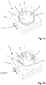
- the in Figs. 1a, 1b The socket 1 shown serves for the electrical contact of a mains plug 2 ( Figs. 2a-2e ), which has several, here only two example contact pins 3 .
- the socket 1 has a base 4 with a base face (plug base) 5, which has several, here two, holes 6 , and with several, here two, contacts 7 arranged behind the holes 6 ( Figs. 2a-2e ), e.g. in the form of sockets, for electrically contacting a contact pin 3 of the mains plug 2 inserted through the holes 6, as well as one for inserting the mains plug 2 provided, here only as an example, annular collar 8.
- the collar 8 is attached to the base 4 from the Fig. 1a shown rear end position to the one in Fig. 1b shown front end position, in which the collar 8 projects further forwards over the base front side 5 than in the rear end position and surrounds the base front side 5 like a collar. In its extended position, the collar 8 serves as contact protection for the contact pins 3 of the mains plug 2 as long as these are not yet fully inserted into the holes 6.
- the base 4 is formed by a socket housing 9 , which here has a rectangular, in particular square, outer contour, merely as an example.
- the base front side 5 is formed by the front of the socket housing 9.
- the base 4 has several complementary connection contacts 10 on two opposite sides, here three connection plugs 10a and three connection sockets 10b ( Figs. 4a, 4b ).
- the collar 8 On its inner peripheral side, the collar 8 has two protective contacts 11, here in the form of contact springs, which each interact with an electrical protective contact of the mains plug 2 and which are electrically connected to an earthing connection of the socket housing 9, here with one of the connection plugs 10a and with one of the connection sockets 10b, e.g. by means of a sliding contact, in every position of the collar 8.
- the leading protective contact 11 earths conductive housing parts of devices before the contact pins 3 reach the live contacts 7.
- the outer contour of the base housing 9 can also be circular, for example.
- plug-in connection contacts 10, 10a, 10b shown can alternatively be present on the socket housing 9 and/or on the collar 8.
- the collar 8 in the rear end position is flush with both the base front side 5 and the rest of the front side of the socket housing 9.
- the extension mechanism 12 has a lever arm 14 pivotably mounted on the base 4, which is hinged at one end to the collar 8 and at the other end, at least in the rear end position of the collar 8, projects into the path of movement of the contact pins 3.
- the lever arm 14 is pivotally mounted and longitudinally displaceable by means of a longitudinal slot 15 on a bearing pin 16 of the base 4.
- the lever arm 14 is preferably made of electrically non-conductive material.
- the electrical connections between the contacts 7 and their associated connection contacts 10 can each have an electrical switch 17 actuated by the collar 8 or the extension mechanism 12, which in the Fig. 3b shown, front end position of the collar 8 is closed and in all other positions of the collar 8 is open, as in Fig. 3a for the rear end position of the collar 8.
- the switch 17 can, for example, have a deflectable contact spring 18 which is attached to the contact 7 in an electrically conductive manner and whose free spring end rests against the connection contact 10 in an electrically conductive manner in the front end position of the collar 8 and is lifted off the connection contact 10 in all other positions of the collar 8. This ensures that the contacts 7 can only be current-carrying in the front end position of the collar 8.
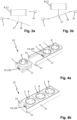
- FIGs. 4a, 4b A multiple socket 20 composed of several, here three sockets 1 is shown, whereby in Fig. 4b all sockets 1 are inserted into a U-profile 21 and in Fig. 4a a last socket 1 has not yet been pushed into the U-profile 21.
- the U-profile 21 has inner profile strips 22 on its two opposite profile legs and the socket housing 1 has longitudinal grooves 23 on two opposite sides, with which the socket housing 1 is guided on the profile strips 22 of the U-profile 21.
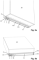
- Figs. 5a, 5b show a lighting device 30 with a lamp 31, with two sockets 1 and with a double U-profile 32, wherein the lamp 31 is accommodated in one U-profile 32a and the sockets 1 and further modules 33 are inserted into the other U-profile 32b of the double U-profile 32.
- the lamp 31 can, for example, have an LED strip that is arranged in the U-profile 32a and a transmissive light bar that closes the U-profile 32a.
- the lighting device 30 is arranged on the underside of an upper cabinet 34 .
Landscapes
- Engineering & Computer Science (AREA)
- General Engineering & Computer Science (AREA)
- Details Of Connecting Devices For Male And Female Coupling (AREA)
- Connector Housings Or Holding Contact Members (AREA)
Description
- Die Erfindung betrifft eine Steckdose für einen Netzstecker mit zumindest zwei Kontaktstiften, aufweisend einen Sockel mit einer Sockelstirnseite, welche mindestens zwei Löcher aufweist, und mit mindestens zwei hinter den Löchern angeordneten Kontakten zur elektrischen Kontaktierung je eines durch die Löcher eingeführten Kontaktstifts des Netzsteckers und einen zum Einstecken des Netzsteckers vorgesehenen Kragen, der am Sockel aus einer hinteren Endstellung in eine vordere Endstellung, in welcher der Kragen über die Sockelstirnseite weiter als in der hinteren Endstellung nach vorne vorsteht und die Sockelstirnseite kragenartig umgibt, beweglich gelagert ist.
- Eine derartige Steckdose mit beweglich gelagertem Kragen ist beispielsweise durch die
WO 2020/077371 A1 bekannt geworden. Hier ist der Kragen in der Art eines Druckknopfes bzw. Drucktasters ausgeführt, der mittels Federn in seine Ausfahrstellung federnd vorgespannt und mittels einer lösbaren Rastklinke in seiner Einfahrstellung temporär verrastbar ist. Durch Antippen in der eingefahrenen Stellung kann der Kragen aus seiner Verrastung an der Rastklinke ausgelöst werden und springt in seine ausgefahrene Stellung. Umgekehrt kann der Kragen von seiner ausgefahrenen Stellung durch Eindrücken gegen die Kraft der Federn wieder in seine Einfahrstellung verbracht und dann an der Rastklinke verrastet werden. - Demgegenüber liegt der vorliegenden Erfindung die Aufgabe zugrunde, bei einer Steckdose der eingangs genannten Art den Kragen auf andere Weise auszufahren.
- Diese Aufgabe wird erfindungsgemäß gelöst durch einen Ausfahrmechanismus, der einerseits an dem Kragen angreift und andererseits zumindest in der hinteren Endstellung des Kragens zwischen der Sockelstirnseite und den Kontakten in die Bewegungsbahn mindestens eines der zwei Kontaktstifte eingreift und der ausgebildet ist, den Kragen durch den mindestens einen eingeführten Kontaktstift aus der hinteren in die vordere Endstellung auszufahren.
- Erfindungsgemäß wird der Kragen durch Einführen der Kontaktstifte des Netzsteckers in die Steckdose aus der hinteren in die vordere Endstellung ausgefahren.
- Bei bevorzugten Ausführungsformen weist der Ausfahrmechanismus einen am Sockel schwenkbar gelagerten Hebelarm auf, der einenends an dem Kragen angreift, insbesondere daran angelenkt ist, und anderenends zumindest in der hinteren Endstellung des Kragens in die Bewegungsbahn des mindestens einen Kontaktstifts hineinragt. Durch den eingeführten Kontaktstift wird der Hebelarm aus der Bewegungsbahn ausgelenkt und dadurch der Kragen - gegenläufig zu dem Kontaktstift - ausgefahren. Der Hebelarm kann beispielsweise mittels eines Längsschlitzes an einem Lagerzapfen des Sockels sowohl schwenkbar gelagert als auch längsverschiebbar geführt sein.
- Vorzugsweise ist der Kragen gegen die Wirkung einer Rückstellkraft, insbesondere in Form einer Rückstellfeder, aus der hinteren in die vordere Endstellung bewegbar und damit in die hintere Endstellung vorgespannt. In der hinteren Endstellung schließt der Kragen bevorzugt bündig mit der Sockelstirnseite ab, so dass sich eine plane Steckdosenvorderseite ergibt.
- Besonders bevorzugt weist die elektrische Verbindung zwischen zumindest einem der Kontakte und einem zugehörigen Anschlusskontakt eines Steckdosengehäuses einen von dem Kragen oder dem Ausfahrmechanismus betätigten, elektrischen Schalter auf, der in der hinteren Endstellung des Kragens geöffnet und zumindest in der vorderen Endstellung des Kragens geschlossen ist. Durch diese Maßnahme ist sichergestellt, dass die Kontakte nur bei ausgefahrenem Kragen stromführend sein können. Vorzugsweise ist der elektrische Schalter ausschließlich in der vorderen Endstellung des Kragens geschlossen, so dass die Kontakte nur bei maximal ausgefahrenem Kragen stromführend sind. Beispielsweise kann der elektrische Schalter eine von dem Kragen oder dem Ausfahrmechanismus auslenkbare Kontaktfeder aufweisen, die in der hinteren Endstellung des Kragens von einem Gegenkontakt des Schalters abgehoben und zumindest in der vorderen Endstellung des Kragens an dem Gegenkontakt elektrisch leitend anliegt.
- Vorzugsweise weist der Kragen an seiner inneren Umfangsseite mindestens einen mit einem Schutzkontakt des Netzsteckers zusammenwirkenden Schutzkontakt auf, der mit einem Erdungsanschluss eines Steckdosengehäuses dauerhaft elektrisch verbunden ist, z.B. mittels eines Schleifkontakts. Durch diese Maßnahme wird die Steckdose zu einer Schutzkontakt-Steckdose weitergebildet.
- Bei bevorzugten Ausführungsformen weist ein Steckdosengehäuse den Sockel auf. Das Steckdosengehäuse kann eine kreisrunde oder eine rechteckige, insbesondere quadratische Außenkontur aufweisen. Vorteilhaft weist das Steckdosengehäuse an zwei einander gegenüberliegenden Seiten jeweils komplementäre Anschlusskontakte auf, um so zwei Steckdosen miteinander elektrisch verbinden zu können. Statt komplementärer Anschlusskontakte können alternativ am Steckdosengehäuse und/oder am Kragen auch handelsübliche Klemm- oder Schraubanschlüsse vorhanden sein.
- Die Erfindung betrifft auch eine Mehrfachsteckdose mit mehreren entlang einer Reihe in einem U-Profil angeordneten, wie oben ausgebildeten Steckdosen. Vorzugsweise weisen die Steckdosen und das U-Profil miteinander zusammenwirkende Führungen, wie z.B. Führungsnuten und -vorsprünge, auf, mittels denen die Steckdosen in das U-Profil eingeschoben und darin gehalten sind. Vorteilhaft kontaktieren beim Zusammenschieben zweier benachbarter Steckdosen Anschlusskontakte der einen Steckdose komplementäre Anschlusskontakte der anderen Steckdose, um so Versorgungsleitungen von einer Steckdose zur nächsten Steckdose weiterzuleiten.
- Die Erfindung betrifft schließlich auch eine Leuchtenvorrichtung mit mindestens einem U-Profil, in dem eine Leuchte und mindestens eine wie oben ausgebildete Steckdose oder Mehrfachsteckdose aufgenommen sind.
- Vorzugsweise weist die Leuchtenvorrichtung ein Doppel-U-Profil auf, wobei die Leuchte in dem einen U-Profil und die mindestens eine Steckdose oder Mehrfachsteckdose in dem anderen U-Profil des Doppel-U-Profils aufgenommen sind. Die Leuchte kann beispielsweise einen LED-Streifen, der in das U-Profil eingeklebt ist, und eine transmissive Lichtleiste, die das U-Profil verschließt, aufweisen. Durch das Doppel-U-Profil sind die Leuchte und die Steckdose(n) voneinander räumlich getrennt. Je nach Anforderung können mehrere Steckdosen oder Mehrfachsteckdosen sowie weitere Module in das U-Profil eingeschoben werden.
- Weitere Vorteile der Erfindung ergeben sich aus der Beschreibung, den Ansprüchen und der Zeichnung. Ebenso können die vorstehenden genannten und die noch weiter aufgeführten Merkmale je für sich oder zu mehreren in beliebigen Kombinationen Verwendung finden. Die gezeigten und beschriebenen Ausführungsformen sind nicht als abschließende Aufzählung zu verstehen, sondern haben vielmehr beispielhaften Charakter für die Schilderung der Erfindung.
- Es zeigen:
- Fign. 1a, 1b
- eine erfindungsgemäße Steckdose mit einem verfahrbaren Kragen in einer eingefahrenen, hinteren Endstellung (
Fig. 1a ) und in einer ausgefahrenen, vorderen Endstellung (Fig. 1b ), jeweils in einer perspektivischen Ansicht; - Fign. 2a-2e
- das durch Einstecken eines Netzstreckers in die erfindungsgemäße Steckdose bewirkte Ausfahren des Kragens, jeweils in einem Längsschnitt;
- Fign. 3a, 3b
- schematisch einen von dem Kragen betätigten, elektrischen Schalter der erfindungsgemäßen Steckdose, der in der eingefahrenen Endstellung des Kragens geöffnet ist (
Fig. 3a ) und in der ausgefahrenen Endstellung des Kragens geschlossen ist (Fig. 3b ); - Fign. 4a, 4b
- eine aus mehreren erfindungsgemäßen Steckdosen zusammengesetzte Mehrfachsteckdose, wobei in
Fig. 4b alle Steckdosen in ein U-Profil eingeschoben sind und inFig. 4a eine letzte Steckdose noch nicht in das U-Profil eingeschoben ist; und - Fign. 5a, 5b
- eine Leuchtenvorrichtung mit mehreren erfindungsgemäßen Steckdosen.
- Die in
Fign. 1a, 1b gezeigte Steckdose 1 dient zur elektrischen Kontaktierung eines Netzsteckers 2 (Fign. 2a-2e ), der mehrere, hier lediglich beispielhaft zwei Kontaktstifte 3 aufweist. - Die Steckdose 1 hat einen Sockel 4 mit einer Sockelstirnseite (Steckergrundfläche) 5, welche mehrere, hier zwei Löcher 6 aufweist, und mit mehreren, hier zwei, hinter den Löchern 6 angeordneten Kontakten 7 (
Fign. 2a-2e ), z.B. in Form von Buchsen, zur elektrischen Kontaktierung je eines durch die Löcher 6 eingeführten Kontaktstifts 3 des Netzsteckers 2, sowie einen zum Einstecken des Netzsteckers 2 vorgesehenen, hier lediglich beispielhaft ringförmigen Kragen 8. Der Kragen 8 ist am Sockel 4 aus der inFig. 1a gezeigten, hinteren Endstellung in die inFig. 1b gezeigte vordere Endstellung, in welcher der Kragen 8 über die Sockelstirnseite 5 weiter als in der hinteren Endstellung nach vorne vorsteht und die Sockelstirnseite 5 kragenartig umgibt, beweglich gelagert. Der Kragen 8 dient in seiner ausgefahrenen Stellung als Berührungsschutz für die Kontaktstifte 3 des Netzsteckers 2, solange diese noch nicht vollständig in die Löcher 6 eingeführt sind. - Der Sockel 4 ist durch ein Steckdosengehäuse 9 gebildet, das hier lediglich beispielhaft eine rechteckige, insbesondere quadratische Außenkontur hat. Die Sockelstirnseite 5 ist durch die Vorderseite des Steckdosengehäuses 9 gebildet. Der Sockel 4 weist an zwei einander gegenüberliegenden Seiten jeweils mehrere komplementäre Anschlusskontakte 10, hier drei Anschlussstecker 10a und drei Anschlussbuchsen 10b (
Fign. 4a, 4b ) auf. An seiner inneren Umfangsseite weist der Kragen 8 zwei jeweils mit einem elektrischen Schutzkontakt des Netzsteckers 2 zusammenwirkende Schutzkontakte 11, hier in Form von Kontaktfedern, auf, die in jeder Stellung des Kragens 8 mit einem Erdungsanschluss des Steckdosengehäuses 9, hier mit einem der Anschlussstecker 10a und mit einer der Anschlussbuchsen 10b, elektrisch verbunden sind, z.B. mittels eines Schleifkontakts. Durch den vorauseilenden Schutzkontakt 11 sind leitfähige Gehäuseteile von Geräten geerdet, bevor die Kontaktstifte 3 die spannungsführenden Kontakte 7 erreichen. - Alternativ kann die Außenkontur des Sockelgehäuses 9 beispielsweise auch kreisrund ausgebildet sein.
- Statt der gezeigten Plugin-Anschlusskontakte 10, 10a, 10b können alternativ am Steckdosengehäuse 9 und/oder am Kragen 8 auch handelsübliche Klemm- oder Schraubanschlüsse vorhanden sein.
- Wie in
Fig. 1a gezeigt, schließt der Kragen 8 in der hinteren Endstellung bündig sowohl mit der Sockelstirnseite 5 als auch mit der übrigen Vorderseite des Steckdosengehäuses 9 ab. - Wie in
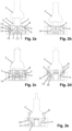
Fign. 2a-2e gezeigt, wird beim Einstecken des Netzsteckers 2 in die Löcher 6 der Kragen 8 mittels eines vom Netzstecker 2 angetriebenen Ausfahrmechanismus 12 aus der hinteren Endstellung gegen die Wirkung einer Rückstellfeder 13 in die vordere Endstellung ausgefahren. Beim Ausstecken des Netzsteckers 2 wird der Kragen 8 von der Rückstellfeder 13 zurück in seine hintere Endstellung eingefahren. Der am Kragen 8 angreifende Ausfahrmechanismus 12 greift zumindest in der hinteren Endstellung des Kragens 8 zwischen der Sockelstirnseite 5 und den Kontakten 7 jeweils in die Bewegungsbahn der beiden Kontaktstifte 3 ein und wird durch die eingeführten Kontaktstifte 3 aus deren Bewegungsbahn ausgelenkt, wodurch der Kragen 8 aus der hinteren in die vordere Endstellung ausgefahren wird. - Im gezeigten Ausführungsbeispiel weist der Ausfahrmechanismus 12 einen am Sockel 4 schwenkbar gelagerten Hebelarm 14 auf, der einenends an dem Kragen 8 angelenkt ist und anderenends, zumindest in der hinteren Endstellung des Kragens 8, in die Bewegungsbahn der Kontaktstifte 3 hineinragt. Der Hebelarm 14 ist mittels eines Längsschlitzes 15 an einem Lagerzapfen 16 des Sockels 4 sowohl schwenkbar gelagert als auch längsverschiebbar geführt. Bevorzugt ist der Hebelarm 14 aus elektrisch nicht leitendem Material.
- In
Fig. 2a sind die Kontaktstifte 3 des Netzsteckers 2 nicht in die Löcher 6 eingeführt, so dass sich der Kragen 8 aufgrund der Rückstellfeder 13 in seiner hinteren Endstellung befindet und die Hebelarme 14 zwischen der Sockelstirnseite 5 und den Kontakten 7 in die Bewegungsbahn der beiden Kontaktstifte 3 hineinragen. - In
Fig. 2b sind die Kontaktstifte 3 durch die Löcher 6 in den Sockel 4 so weit eingeführt, dass sie an den Hebelarmen 14 anliegen. - In
Fig. 2c sind die Kontaktstifte 3 weiter in den Sockel 4 eingeführt, wodurch die Hebelarme 14 von den Kontaktstiften 3 um die Lagerzapfen 16 verschwenkt und in dem Längsschlitz 15 verschoben sind und der an den Hebelarmen 14 angelenkte Kragen 8 aus seiner hinteren Endstellung nach vorne ausgefahren ist. - In
Fig. 2d sind die Hebelarme 14 durch die weiter eingeführten Kontaktstifte 3 vollständig aus der Bewegungsbahn der Kontaktstifte 3 ausgelenkt, wodurch der Kragen 8 in seine vordere Endstellung ausgefahren ist. - In
Fig. 2e sind die noch weiter eingeführten Kontaktstifte 3 schließlich in den Kontakten 7 aufgenommen und dabei elektrisch kontaktiert, wobei die Hebelarme 14 außen an den Kontaktstifte 3 anliegen. Durch den ausgefahren Kragen 8, der die ganze Sockelstirnseite 5 umschließt, und durch die erst bei vollständig eingeführtem Netzstecker 2 erfolgende Kontaktierung der Kontakte 7 ist Berührungsschutz gegeben. - Wie in
Fign. 3a, 3b schematisch gezeigt, kann die elektrischen Verbindungen zwischen den Kontakten 7 und ihren zugehörigen Anschlusskontakten 10 jeweils einen von dem Kragen 8 oder dem Ausfahrmechanismus 12 betätigten, elektrischen Schalter 17 aufweisen, der in der inFig. 3b gezeigten, vorderen Endstellung des Kragens 8 geschlossen und in allen anderen Stellungen des Kragens 8 geöffnet ist, wie inFig. 3a für die hintere Endstellung des Kragens 8 gezeigt ist. Der Schalter 17 kann beispielsweise eine auslenkbare Kontaktfeder 18 aufweisen, die am Kontakt 7 elektrisch leitend befestigt ist und deren freies Federende in der vorderen Endstellung des Kragens 8 am Anschlusskontakt 10 elektrisch leitend anliegt und in allen anderen Stellungen des Kragens 8 von dem Anschlusskontakt 10 abgehoben ist. So ist sichergestellt, dass die Kontakte 7 nur in der vorderen Endstellung des Kragens 8 stromführend sein können. - In
Fign. 4a, 4b ist eine aus mehreren, hier drei Steckdosen 1 zusammengesetzte Mehrfachsteckdose 20 gezeigt, wobei inFig. 4b alle Steckdosen 1 in ein U-Profil 21 eingeschoben sind und inFig. 4a eine letzte Steckdose 1 noch nicht in das U-Profil 21 eingeschoben ist. Das U-Profil 21 weist an seinen beiden einander gegenüberliegenden Profilschenkeln jeweils innenseitige Profilleisten 22 und das Steckdosengehäuse 1 an zwei einander gegenüberliegenden Seiten jeweils Längsnuten 23 auf, mit denen das Steckdosengehäuse 1 an den Profilleisten 22 des U-Profils 21 geführt ist. Beim Zusammenschieben zweier benachbarter Steckdosen 1 greifen die Anschlusskontakte 10 der einen Steckdose 1, also die Anschlussstecker 10a, in die komplementären Anschlusskontakte 10 der anderen Steckdose 1, also in die Anschlussbuchsen 10b, ein, wodurch Versorgungsleitungen von einer Steckdose 1 zur nächsten Steckdose 1 weitergeleitet werden. -
Fign. 5a, 5b zeigen eine Leuchtenvorrichtung 30 mit einer Leuchte 31, mit zwei Steckdosen 1 und mit einem Doppel-U-Profil 32, wobei die Leuchte 31 in dem einen U-Profil 32a aufgenommen und die Steckdosen 1 und weitere Module 33 in dem anderen U-Profil 32b des Doppel-U-Profils 32 eingeschoben sind. Die Leuchte 31 kann beispielsweise einen LED-Streifen, der in dem U-Profil 32a angeordnet ist, und eine transmissive Lichtleiste aufweisen, die das U-Profil 32a verschließt. Im gezeigten Ausführungsbeispiel ist die Leuchtenvorrichtung 30 unterseitig an einem Oberschrank 34 angeordnet.
Claims (14)
- Steckdose (1) für einen Netzstecker (2) mit zumindest zwei Kontaktstiften (3), aufweisend- einen Sockel (4) mit einer Sockelstirnseite (5), welche mindestens zwei Löcher (6) aufweist, und mit mindestens zwei hinter den Löchern (6) angeordneten Kontakten (7) zur elektrischen Kontaktierung je eines durch die Löcher (6) eingeführten Kontaktstifts (3) des Netzsteckers (2), und- einen zum Einstecken des Netzsteckers (2) vorgesehenen Kragen (8), der am Sockel (4) aus einer hinteren Endstellung in eine vordere Endstellung, in welcher der Kragen (8) über die Sockelstirnseite (5) weiter als in der hinteren Endstellung nach vorne vorsteht und die Sockelstirnseite (5) kragenartig umgibt, beweglich gelagert ist,gekennzeichnet durch einen Ausfahrmechanismus (12), der einerseits an dem Kragen (8) angreift und andererseits zumindest in der hinteren Endstellung des Kragens (8) zwischen der Sockelstirnseite (5) und den Kontakten (7) in die Bewegungsbahn mindestens eines der zwei Kontaktstifte (3) eingreift und der ausgebildet ist, den Kragen (8) durch den mindestens einen eingeführten Kontaktstift (3) aus der hinteren in die vordere Endstellung auszufahren.
- Steckdose nach Anspruch 1, dadurch gekennzeichnet, dass der Ausfahrmechanismus (12) einen am Sockel (4) schwenkbar gelagerten Hebelarm (14) aufweist, der einenends an dem Kragen (8) angreift, insbesondere daran angelenkt ist, und anderenends zumindest in der hinteren Endstellung des Kragens (8) in die Bewegungsbahn des mindestens einen Kontaktstifts (3) hineinragt.
- Steckdose nach Anspruch 2, dadurch gekennzeichnet, dass der Hebelarm (14) mittels eines Längsschlitzes (15) an einem Lagerzapfen (16) des Sockels (4) sowohl schwenkbar gelagert als auch längsverschiebbar geführt ist.
- Steckdose nach einem der vorhergehenden Ansprüche, dadurch gekennzeichnet, dass der Kragen (8) gegen die Wirkung einer Rückstellkraft, insbesondere in Form einer Rückstellfeder (13), aus der hinteren in die vordere Endstellung bewegbar ist.
- Steckdose nach einem der vorhergehenden Ansprüche, dadurch gekennzeichnet, dass der Kragen (8) in der hinteren Endstellung bündig mit der Sockelstirnseite (5) abschließt.
- Steckdose nach einem der vorhergehenden Ansprüche, dadurch gekennzeichnet, dass die elektrische Verbindung zwischen zumindest einem der Kontakte (7) und einem zugehörigen Anschlusskontakt (10) eines Steckdosengehäuses (9) einen von dem Kragen (8) oder dem Ausfahrmechanismus (12) betätigten, elektrischen Schalter (17) aufweist, der in der hinteren Endstellung des Kragens (8) geöffnet und zumindest in der vorderen Endstellung des Kragens (8) geschlossen ist.
- Steckdose nach Anspruch 6, dadurch gekennzeichnet, dass der elektrische Schalter (17) ausschließlich in der vorderen Endstellung des Kragens (8) geschlossen ist.
- Steckdose nach Anspruch 6 oder 7, dadurch gekennzeichnet, dass der elektrische Schalter (17) eine von dem Kragen (8) oder dem Ausfahrmechanismus (12) auslenkbare Kontaktfeder (18) aufweist, die in der hinteren Endstellung des Kragens (8) von einem Gegenkontakt (10) des Schalters (17) abgehoben und zumindest in der vorderen Endstellung des Kragens (8) an dem Gegenkontakt (10) elektrisch leitend anliegt.
- Steckdose nach einem der vorhergehenden Ansprüche, dadurch gekennzeichnet, dass der Kragen (8) an seiner inneren Umfangsseite mindestens einen mit einem Schutzkontakt des Netzsteckers (2) zusammenwirkenden Schutzkontakt (11) aufweist, der mit einem Erdungsanschluss (10) eines Steckdosengehäuses (9) elektrisch verbunden ist.
- Steckdose nach einem der vorhergehenden Ansprüche, gekennzeichnet durch ein Steckdosengehäuse (9), das den Sockel (4) aufweist und bevorzugt eine kreisrunde oder eine rechteckige, insbesondere quadratische Außenkontur aufweist.
- Steckdose nach Anspruch 10, dadurch gekennzeichnet, dass das Steckdosengehäuse (9) an zwei einander gegenüberliegenden Seiten jeweils komplementäre Anschlusskontakte (10a, 10b) aufweist.
- Mehrfachsteckdose (20) mit mehreren entlang einer Reihe in einem U-Profil (21) angeordneten Steckdosen (1) nach einem der vorhergehenden Ansprüche.
- Leuchtenvorrichtung (30) mit mindestens einem U-Profil (32a, 32b), in dem eine Leuchte (31) und mindestens eine Steckdose (1) oder Mehrfachsteckdose (20) nach einem der vorhergehenden Ansprüche aufgenommen sind.
- Leuchtenvorrichtung nach Anspruch 13, gekennzeichnet durch ein Doppel-U-Profil (32), wobei die Leuchte (31) in dem einen U-Profil (32a) und die mindestens eine Steckdose (1) oder Mehrfachsteckdose (20) in dem anderen U-Profil (32b) des Doppel-U-Profils (32) aufgenommen sind.
Applications Claiming Priority (1)
| Application Number | Priority Date | Filing Date | Title |
|---|---|---|---|
| DE202022102254.2U DE202022102254U1 (de) | 2022-04-27 | 2022-04-27 | Steckdose mit ausfahrbarem Kragen sowie Leuchtenvorrichtung mit einer solchen Steckdose |
Publications (2)
| Publication Number | Publication Date |
|---|---|
| EP4270673A1 EP4270673A1 (de) | 2023-11-01 |
| EP4270673B1 true EP4270673B1 (de) | 2025-02-19 |
Family
ID=82217853
Family Applications (1)
| Application Number | Title | Priority Date | Filing Date |
|---|---|---|---|
| EP23162834.8A Active EP4270673B1 (de) | 2022-04-27 | 2023-03-20 | Steckdose mit ausfahrbarem kragen sowie leuchtenvorrichtung mit einer solchen steckdose |
Country Status (3)
| Country | Link |
|---|---|
| US (1) | US12451640B2 (de) |
| EP (1) | EP4270673B1 (de) |
| DE (1) | DE202022102254U1 (de) |
Families Citing this family (2)
| Publication number | Priority date | Publication date | Assignee | Title |
|---|---|---|---|---|
| DE202022102254U1 (de) * | 2022-04-27 | 2022-06-09 | Nimbus Group Gmbh | Steckdose mit ausfahrbarem Kragen sowie Leuchtenvorrichtung mit einer solchen Steckdose |
| AT527316B1 (de) * | 2023-12-21 | 2025-01-15 | Mass Tech Innovations Gmbh | Steckdose |
Citations (5)
| Publication number | Priority date | Publication date | Assignee | Title |
|---|---|---|---|---|
| US5067907A (en) | 1990-10-12 | 1991-11-26 | Shotey Michael J | Cover and sheath for electrical outlets |
| US20060172583A1 (en) | 2005-01-15 | 2006-08-03 | Duhe Jerry R Jr | Securing electrical receptacle with alternate on/off positions |
| WO2020077371A1 (de) | 2018-10-19 | 2020-04-23 | Ahmic Selmir | Steckdose |
| US20200136321A1 (en) | 2017-07-10 | 2020-04-30 | Feifan HU | Insertion detection device for plug pins and a safety socket |
| WO2021233650A1 (de) | 2020-05-18 | 2021-11-25 | Nimbus Group Gmbh | Asymmetrische linearlinse und zugehörige linearleuchte |
Family Cites Families (10)
| Publication number | Priority date | Publication date | Assignee | Title |
|---|---|---|---|---|
| US2444843A (en) * | 1943-08-27 | 1948-07-06 | Modrey Patents Corp | Electrical plug and socket connector with retractable contacts |
| US3147055A (en) * | 1961-12-11 | 1964-09-01 | George J Rubens | Resilient safety sleeve for electrical prongs |
| US3201740A (en) * | 1964-07-17 | 1965-08-17 | George J Rubens | Adhesively attached resilient safety device for electrical connectors |
| US3363216A (en) * | 1965-10-21 | 1968-01-09 | Patrick J. Benedetto | Safety attachment for electrical outlet fixtures |
| US3449706A (en) * | 1967-10-12 | 1969-06-10 | Hubbell Inc Harvey | Protective enclosure for electrical wiring devices |
| US4293733A (en) * | 1979-11-13 | 1981-10-06 | John A. Weithman | Safety cover for electrical outlets |
| US4391481A (en) * | 1981-03-30 | 1983-07-05 | Golden Theodore A | Child-proof electrical plug sheath |
| US5551884A (en) * | 1995-01-25 | 1996-09-03 | Burkhart, Sr.; Steven A. | Locking electrical outlet |
| US5944542A (en) * | 1997-06-27 | 1999-08-31 | Han Y. Lee | Plug safety adapter for anti-electric shock |
| DE202022102254U1 (de) * | 2022-04-27 | 2022-06-09 | Nimbus Group Gmbh | Steckdose mit ausfahrbarem Kragen sowie Leuchtenvorrichtung mit einer solchen Steckdose |
-
2022
- 2022-04-27 DE DE202022102254.2U patent/DE202022102254U1/de not_active Expired - Lifetime
-
2023
- 2023-03-20 EP EP23162834.8A patent/EP4270673B1/de active Active
- 2023-04-17 US US18/301,570 patent/US12451640B2/en active Active
Patent Citations (5)
| Publication number | Priority date | Publication date | Assignee | Title |
|---|---|---|---|---|
| US5067907A (en) | 1990-10-12 | 1991-11-26 | Shotey Michael J | Cover and sheath for electrical outlets |
| US20060172583A1 (en) | 2005-01-15 | 2006-08-03 | Duhe Jerry R Jr | Securing electrical receptacle with alternate on/off positions |
| US20200136321A1 (en) | 2017-07-10 | 2020-04-30 | Feifan HU | Insertion detection device for plug pins and a safety socket |
| WO2020077371A1 (de) | 2018-10-19 | 2020-04-23 | Ahmic Selmir | Steckdose |
| WO2021233650A1 (de) | 2020-05-18 | 2021-11-25 | Nimbus Group Gmbh | Asymmetrische linearlinse und zugehörige linearleuchte |
Non-Patent Citations (1)
| Title |
|---|
| D6 - AUSZUG KATALOG HÄFELE |
Also Published As
| Publication number | Publication date |
|---|---|
| US20230352871A1 (en) | 2023-11-02 |
| DE202022102254U1 (de) | 2022-06-09 |
| US12451640B2 (en) | 2025-10-21 |
| EP4270673A1 (de) | 2023-11-01 |
Similar Documents
| Publication | Publication Date | Title |
|---|---|---|
| EP4270673B1 (de) | Steckdose mit ausfahrbarem kragen sowie leuchtenvorrichtung mit einer solchen steckdose | |
| DE102020122135A1 (de) | Anschlussanordnung, Steckverbinder und elektronisches Gerät | |
| EP3602692A1 (de) | Kompakte leiteranschlussklemme | |
| EP2879243A1 (de) | Steckerteil | |
| EP3830908B1 (de) | Steckdose | |
| DE102022118020A1 (de) | Steckanschluss, Steckverbinder und Reihung aus Steckverbindern | |
| DE202014010621U1 (de) | Steckverbinder | |
| DE102017124670B4 (de) | Elektrische Steckverbindung | |
| EP2613219A2 (de) | Gehäuse für ein Computersystem sowie Computersystem mit einem derartigen Gehäuse | |
| WO2019052852A1 (de) | Anschlusseinrichtung zum anschliessen einer elektrischen leitung | |
| WO2019034448A1 (de) | Elektrischer steckverbinder | |
| EP0480007B1 (de) | Vorrichtung zur verbindung von steuerstromleitungen | |
| BE1025732B1 (de) | Anschlusseinrichtung zum Anschließen einer elektrischen Leitung | |
| DE102016111461A1 (de) | Federkontakt | |
| DE202017101673U1 (de) | Elektrischer Steckverbinder | |
| DE202016105823U1 (de) | Steckverbindung | |
| DE202018106082U1 (de) | Anschlussleiste | |
| DE3308253A1 (de) | Steckdose | |
| WO2022180006A1 (de) | Hochvoltsteckverbinderanordnung | |
| DE102024115587B3 (de) | Anschlussblock mit Hebel | |
| DE10211814C1 (de) | Schutzkontaktsteckdose mit im Steckdosensockel integrierter Berührungsschutzvorrichtung | |
| DE102013014202A1 (de) | Steckverbindersystem | |
| EP2722933B1 (de) | Steckanordnung zum Anschluss elektrischer Leiter an eine elektrische Baugruppe | |
| DE202004010325U1 (de) | Koaxialsteckverbinder mit Schaltwerk für elektrischen Kontakt | |
| DE202016103070U1 (de) | Mehrzweck-Anschlussvorrichtung |
Legal Events
| Date | Code | Title | Description |
|---|---|---|---|
| PUAI | Public reference made under article 153(3) epc to a published international application that has entered the european phase |
Free format text: ORIGINAL CODE: 0009012 |
|
| STAA | Information on the status of an ep patent application or granted ep patent |
Free format text: STATUS: THE APPLICATION HAS BEEN PUBLISHED |
|
| AK | Designated contracting states |
Kind code of ref document: A1 Designated state(s): AL AT BE BG CH CY CZ DE DK EE ES FI FR GB GR HR HU IE IS IT LI LT LU LV MC ME MK MT NL NO PL PT RO RS SE SI SK SM TR |
|
| STAA | Information on the status of an ep patent application or granted ep patent |
Free format text: STATUS: REQUEST FOR EXAMINATION WAS MADE |
|
| 17P | Request for examination filed |
Effective date: 20240415 |
|
| RBV | Designated contracting states (corrected) |
Designated state(s): AL AT BE BG CH CY CZ DE DK EE ES FI FR GB GR HR HU IE IS IT LI LT LU LV MC ME MK MT NL NO PL PT RO RS SE SI SK SM TR |
|
| GRAP | Despatch of communication of intention to grant a patent |
Free format text: ORIGINAL CODE: EPIDOSNIGR1 |
|
| STAA | Information on the status of an ep patent application or granted ep patent |
Free format text: STATUS: GRANT OF PATENT IS INTENDED |
|
| RIC1 | Information provided on ipc code assigned before grant |
Ipc: H01R 25/00 20060101ALN20240822BHEP Ipc: H01R 13/514 20060101ALN20240822BHEP Ipc: F21V 33/00 20060101ALN20240822BHEP Ipc: H01R 24/78 20110101ALI20240822BHEP Ipc: H01R 13/703 20060101ALI20240822BHEP Ipc: H01R 13/655 20060101ALI20240822BHEP Ipc: H01R 13/453 20060101AFI20240822BHEP |
|
| INTG | Intention to grant announced |
Effective date: 20240923 |
|
| RAP1 | Party data changed (applicant data changed or rights of an application transferred) |
Owner name: HAEFELE TECHNOLOGY SOLUTIONS GMBH & CO KG |
|
| GRAS | Grant fee paid |
Free format text: ORIGINAL CODE: EPIDOSNIGR3 |
|
| GRAA | (expected) grant |
Free format text: ORIGINAL CODE: 0009210 |
|
| STAA | Information on the status of an ep patent application or granted ep patent |
Free format text: STATUS: THE PATENT HAS BEEN GRANTED |
|
| AK | Designated contracting states |
Kind code of ref document: B1 Designated state(s): AL AT BE BG CH CY CZ DE DK EE ES FI FR GB GR HR HU IE IS IT LI LT LU LV MC ME MK MT NL NO PL PT RO RS SE SI SK SM TR |
|
| REG | Reference to a national code |
Ref country code: GB Ref legal event code: FG4D Free format text: NOT ENGLISH |
|
| REG | Reference to a national code |
Ref country code: CH Ref legal event code: EP |
|
| REG | Reference to a national code |
Ref country code: IE Ref legal event code: FG4D Free format text: LANGUAGE OF EP DOCUMENT: GERMAN |
|
| REG | Reference to a national code |
Ref country code: DE Ref legal event code: R096 Ref document number: 502023000570 Country of ref document: DE |
|
| PGFP | Annual fee paid to national office [announced via postgrant information from national office to epo] |
Ref country code: DE Payment date: 20250325 Year of fee payment: 3 |
|
| PGFP | Annual fee paid to national office [announced via postgrant information from national office to epo] |
Ref country code: AT Payment date: 20250417 Year of fee payment: 3 |
|
| REG | Reference to a national code |
Ref country code: NL Ref legal event code: MP Effective date: 20250219 |
|
| PG25 | Lapsed in a contracting state [announced via postgrant information from national office to epo] |
Ref country code: RS Free format text: LAPSE BECAUSE OF FAILURE TO SUBMIT A TRANSLATION OF THE DESCRIPTION OR TO PAY THE FEE WITHIN THE PRESCRIBED TIME-LIMIT Effective date: 20250519 |
|
| PG25 | Lapsed in a contracting state [announced via postgrant information from national office to epo] |
Ref country code: FI Free format text: LAPSE BECAUSE OF FAILURE TO SUBMIT A TRANSLATION OF THE DESCRIPTION OR TO PAY THE FEE WITHIN THE PRESCRIBED TIME-LIMIT Effective date: 20250219 |
|
| PG25 | Lapsed in a contracting state [announced via postgrant information from national office to epo] |
Ref country code: PL Free format text: LAPSE BECAUSE OF FAILURE TO SUBMIT A TRANSLATION OF THE DESCRIPTION OR TO PAY THE FEE WITHIN THE PRESCRIBED TIME-LIMIT Effective date: 20250219 |
|
| PG25 | Lapsed in a contracting state [announced via postgrant information from national office to epo] |
Ref country code: ES Free format text: LAPSE BECAUSE OF FAILURE TO SUBMIT A TRANSLATION OF THE DESCRIPTION OR TO PAY THE FEE WITHIN THE PRESCRIBED TIME-LIMIT Effective date: 20250219 |
|
| REG | Reference to a national code |
Ref country code: LT Ref legal event code: MG9D |
|
| PG25 | Lapsed in a contracting state [announced via postgrant information from national office to epo] |
Ref country code: NO Free format text: LAPSE BECAUSE OF FAILURE TO SUBMIT A TRANSLATION OF THE DESCRIPTION OR TO PAY THE FEE WITHIN THE PRESCRIBED TIME-LIMIT Effective date: 20250519 Ref country code: IS Free format text: LAPSE BECAUSE OF FAILURE TO SUBMIT A TRANSLATION OF THE DESCRIPTION OR TO PAY THE FEE WITHIN THE PRESCRIBED TIME-LIMIT Effective date: 20250619 |
|
| PG25 | Lapsed in a contracting state [announced via postgrant information from national office to epo] |
Ref country code: NL Free format text: LAPSE BECAUSE OF FAILURE TO SUBMIT A TRANSLATION OF THE DESCRIPTION OR TO PAY THE FEE WITHIN THE PRESCRIBED TIME-LIMIT Effective date: 20250219 |
|
| PG25 | Lapsed in a contracting state [announced via postgrant information from national office to epo] |
Ref country code: HR Free format text: LAPSE BECAUSE OF FAILURE TO SUBMIT A TRANSLATION OF THE DESCRIPTION OR TO PAY THE FEE WITHIN THE PRESCRIBED TIME-LIMIT Effective date: 20250219 |
|
| PG25 | Lapsed in a contracting state [announced via postgrant information from national office to epo] |
Ref country code: LV Free format text: LAPSE BECAUSE OF FAILURE TO SUBMIT A TRANSLATION OF THE DESCRIPTION OR TO PAY THE FEE WITHIN THE PRESCRIBED TIME-LIMIT Effective date: 20250219 Ref country code: PT Free format text: LAPSE BECAUSE OF FAILURE TO SUBMIT A TRANSLATION OF THE DESCRIPTION OR TO PAY THE FEE WITHIN THE PRESCRIBED TIME-LIMIT Effective date: 20250620 |
|
| PG25 | Lapsed in a contracting state [announced via postgrant information from national office to epo] |
Ref country code: GR Free format text: LAPSE BECAUSE OF FAILURE TO SUBMIT A TRANSLATION OF THE DESCRIPTION OR TO PAY THE FEE WITHIN THE PRESCRIBED TIME-LIMIT Effective date: 20250520 Ref country code: BG Free format text: LAPSE BECAUSE OF FAILURE TO SUBMIT A TRANSLATION OF THE DESCRIPTION OR TO PAY THE FEE WITHIN THE PRESCRIBED TIME-LIMIT Effective date: 20250219 |
|
| PG25 | Lapsed in a contracting state [announced via postgrant information from national office to epo] |
Ref country code: SE Free format text: LAPSE BECAUSE OF FAILURE TO SUBMIT A TRANSLATION OF THE DESCRIPTION OR TO PAY THE FEE WITHIN THE PRESCRIBED TIME-LIMIT Effective date: 20250219 |
|
| PG25 | Lapsed in a contracting state [announced via postgrant information from national office to epo] |
Ref country code: SM Free format text: LAPSE BECAUSE OF FAILURE TO SUBMIT A TRANSLATION OF THE DESCRIPTION OR TO PAY THE FEE WITHIN THE PRESCRIBED TIME-LIMIT Effective date: 20250219 |
|
| PG25 | Lapsed in a contracting state [announced via postgrant information from national office to epo] |
Ref country code: DK Free format text: LAPSE BECAUSE OF FAILURE TO SUBMIT A TRANSLATION OF THE DESCRIPTION OR TO PAY THE FEE WITHIN THE PRESCRIBED TIME-LIMIT Effective date: 20250219 |
|
| PG25 | Lapsed in a contracting state [announced via postgrant information from national office to epo] |
Ref country code: IT Free format text: LAPSE BECAUSE OF FAILURE TO SUBMIT A TRANSLATION OF THE DESCRIPTION OR TO PAY THE FEE WITHIN THE PRESCRIBED TIME-LIMIT Effective date: 20250219 |
|
| PG25 | Lapsed in a contracting state [announced via postgrant information from national office to epo] |
Ref country code: EE Free format text: LAPSE BECAUSE OF FAILURE TO SUBMIT A TRANSLATION OF THE DESCRIPTION OR TO PAY THE FEE WITHIN THE PRESCRIBED TIME-LIMIT Effective date: 20250219 Ref country code: CZ Free format text: LAPSE BECAUSE OF FAILURE TO SUBMIT A TRANSLATION OF THE DESCRIPTION OR TO PAY THE FEE WITHIN THE PRESCRIBED TIME-LIMIT Effective date: 20250219 |
|
| PG25 | Lapsed in a contracting state [announced via postgrant information from national office to epo] |
Ref country code: RO Free format text: LAPSE BECAUSE OF FAILURE TO SUBMIT A TRANSLATION OF THE DESCRIPTION OR TO PAY THE FEE WITHIN THE PRESCRIBED TIME-LIMIT Effective date: 20250219 |
|
| PG25 | Lapsed in a contracting state [announced via postgrant information from national office to epo] |
Ref country code: SK Free format text: LAPSE BECAUSE OF FAILURE TO SUBMIT A TRANSLATION OF THE DESCRIPTION OR TO PAY THE FEE WITHIN THE PRESCRIBED TIME-LIMIT Effective date: 20250219 |
|
| REG | Reference to a national code |
Ref country code: DE Ref legal event code: R026 Ref document number: 502023000570 Country of ref document: DE |
|
| PLBI | Opposition filed |
Free format text: ORIGINAL CODE: 0009260 |
|
| PG25 | Lapsed in a contracting state [announced via postgrant information from national office to epo] |
Ref country code: LU Free format text: LAPSE BECAUSE OF NON-PAYMENT OF DUE FEES Effective date: 20250320 |
|
| PLAX | Notice of opposition and request to file observation + time limit sent |
Free format text: ORIGINAL CODE: EPIDOSNOBS2 |
|
| REG | Reference to a national code |
Ref country code: BE Ref legal event code: MM Effective date: 20250331 |
|
| 26 | Opposition filed |
Opponent name: MASS TECH INNOVATIONS GMBH Effective date: 20251112 |
|
| PG25 | Lapsed in a contracting state [announced via postgrant information from national office to epo] |
Ref country code: MC Free format text: LAPSE BECAUSE OF FAILURE TO SUBMIT A TRANSLATION OF THE DESCRIPTION OR TO PAY THE FEE WITHIN THE PRESCRIBED TIME-LIMIT Effective date: 20250219 |
|
| PG25 | Lapsed in a contracting state [announced via postgrant information from national office to epo] |
Ref country code: FR Free format text: LAPSE BECAUSE OF NON-PAYMENT OF DUE FEES Effective date: 20250419 |
|
| PG25 | Lapsed in a contracting state [announced via postgrant information from national office to epo] |
Ref country code: BE Free format text: LAPSE BECAUSE OF NON-PAYMENT OF DUE FEES Effective date: 20250331 |
|
| PG25 | Lapsed in a contracting state [announced via postgrant information from national office to epo] |
Ref country code: IE Free format text: LAPSE BECAUSE OF NON-PAYMENT OF DUE FEES Effective date: 20250320 |