EP4269294B1 - Vorrichtung zum überführen und ansammeln von gegenständen und verpackungslinie mit dieser vorrichtung - Google Patents
Vorrichtung zum überführen und ansammeln von gegenständen und verpackungslinie mit dieser vorrichtung Download PDFInfo
- Publication number
- EP4269294B1 EP4269294B1 EP22170517.1A EP22170517A EP4269294B1 EP 4269294 B1 EP4269294 B1 EP 4269294B1 EP 22170517 A EP22170517 A EP 22170517A EP 4269294 B1 EP4269294 B1 EP 4269294B1
- Authority
- EP
- European Patent Office
- Prior art keywords
- accumulation
- objects
- group
- channels
- accumulation channels
- Prior art date
- Legal status (The legal status is an assumption and is not a legal conclusion. Google has not performed a legal analysis and makes no representation as to the accuracy of the status listed.)
- Active
Links
Images




Classifications
-
- B—PERFORMING OPERATIONS; TRANSPORTING
- B65—CONVEYING; PACKING; STORING; HANDLING THIN OR FILAMENTARY MATERIAL
- B65G—TRANSPORT OR STORAGE DEVICES, e.g. CONVEYORS FOR LOADING OR TIPPING, SHOP CONVEYOR SYSTEMS OR PNEUMATIC TUBE CONVEYORS
- B65G47/00—Article or material-handling devices associated with conveyors; Methods employing such devices
- B65G47/52—Devices for transferring articles or materials between conveyors i.e. discharging or feeding devices
- B65G47/68—Devices for transferring articles or materials between conveyors i.e. discharging or feeding devices adapted to receive articles arriving in one layer from one conveyor lane and to transfer them in individual layers to more than one conveyor lane or to one broader conveyor lane, or vice versa, e.g. combining the flows of articles conveyed by more than one conveyor
- B65G47/71—Devices for transferring articles or materials between conveyors i.e. discharging or feeding devices adapted to receive articles arriving in one layer from one conveyor lane and to transfer them in individual layers to more than one conveyor lane or to one broader conveyor lane, or vice versa, e.g. combining the flows of articles conveyed by more than one conveyor the articles being discharged or distributed to several distinct separate conveyors or to a broader conveyor lane
-
- B—PERFORMING OPERATIONS; TRANSPORTING
- B65—CONVEYING; PACKING; STORING; HANDLING THIN OR FILAMENTARY MATERIAL
- B65G—TRANSPORT OR STORAGE DEVICES, e.g. CONVEYORS FOR LOADING OR TIPPING, SHOP CONVEYOR SYSTEMS OR PNEUMATIC TUBE CONVEYORS
- B65G47/00—Article or material-handling devices associated with conveyors; Methods employing such devices
- B65G47/22—Devices influencing the relative position or the attitude of articles during transit by conveyors
- B65G47/26—Devices influencing the relative position or the attitude of articles during transit by conveyors arranging the articles, e.g. varying spacing between individual articles
- B65G47/261—Accumulating articles
- B65G47/265—Accumulating articles with one or more load advancing units travelling along the entire length of the accumulation line
-
- B—PERFORMING OPERATIONS; TRANSPORTING
- B65—CONVEYING; PACKING; STORING; HANDLING THIN OR FILAMENTARY MATERIAL
- B65G—TRANSPORT OR STORAGE DEVICES, e.g. CONVEYORS FOR LOADING OR TIPPING, SHOP CONVEYOR SYSTEMS OR PNEUMATIC TUBE CONVEYORS
- B65G47/00—Article or material-handling devices associated with conveyors; Methods employing such devices
- B65G47/34—Devices for discharging articles or materials from conveyor
- B65G47/46—Devices for discharging articles or materials from conveyor and distributing, e.g. automatically, to desired points
- B65G47/51—Devices for discharging articles or materials from conveyor and distributing, e.g. automatically, to desired points according to unprogrammed signals, e.g. influenced by supply situation at destination
- B65G47/5104—Devices for discharging articles or materials from conveyor and distributing, e.g. automatically, to desired points according to unprogrammed signals, e.g. influenced by supply situation at destination for articles
-
- B—PERFORMING OPERATIONS; TRANSPORTING
- B65—CONVEYING; PACKING; STORING; HANDLING THIN OR FILAMENTARY MATERIAL
- B65G—TRANSPORT OR STORAGE DEVICES, e.g. CONVEYORS FOR LOADING OR TIPPING, SHOP CONVEYOR SYSTEMS OR PNEUMATIC TUBE CONVEYORS
- B65G47/00—Article or material-handling devices associated with conveyors; Methods employing such devices
- B65G47/52—Devices for transferring articles or materials between conveyors i.e. discharging or feeding devices
- B65G47/68—Devices for transferring articles or materials between conveyors i.e. discharging or feeding devices adapted to receive articles arriving in one layer from one conveyor lane and to transfer them in individual layers to more than one conveyor lane or to one broader conveyor lane, or vice versa, e.g. combining the flows of articles conveyed by more than one conveyor
- B65G47/682—Devices for transferring articles or materials between conveyors i.e. discharging or feeding devices adapted to receive articles arriving in one layer from one conveyor lane and to transfer them in individual layers to more than one conveyor lane or to one broader conveyor lane, or vice versa, e.g. combining the flows of articles conveyed by more than one conveyor from a single conveyor lane consisting of one conveyor or several adjacent conveyors
-
- B—PERFORMING OPERATIONS; TRANSPORTING
- B65—CONVEYING; PACKING; STORING; HANDLING THIN OR FILAMENTARY MATERIAL
- B65G—TRANSPORT OR STORAGE DEVICES, e.g. CONVEYORS FOR LOADING OR TIPPING, SHOP CONVEYOR SYSTEMS OR PNEUMATIC TUBE CONVEYORS
- B65G47/00—Article or material-handling devices associated with conveyors; Methods employing such devices
- B65G47/52—Devices for transferring articles or materials between conveyors i.e. discharging or feeding devices
- B65G47/68—Devices for transferring articles or materials between conveyors i.e. discharging or feeding devices adapted to receive articles arriving in one layer from one conveyor lane and to transfer them in individual layers to more than one conveyor lane or to one broader conveyor lane, or vice versa, e.g. combining the flows of articles conveyed by more than one conveyor
- B65G47/69—Devices for transferring articles or materials between conveyors i.e. discharging or feeding devices adapted to receive articles arriving in one layer from one conveyor lane and to transfer them in individual layers to more than one conveyor lane or to one broader conveyor lane, or vice versa, e.g. combining the flows of articles conveyed by more than one conveyor the articles being accumulated temporarily
Definitions
- the present invention relates to an apparatus for transferring and accumulating objects and a packaging line comprising such an apparatus.
- the objects may be bottles, containers or the like.
- an accumulation table which acts as a buffer for the objects coming from the upstream station is known, in particular when jamming occurs upstream and/or during maintenance interventions.
- the use of an accumulation table therefore prevents having to stop the upstream station as well.
- WO2014/076390 presents an accumulation table interposed between an input belt and an output belt, on which rows of objects are transferred and on which heads and/or manipulating robots adapted to move the rows on the table operate.
- Feeding in rows can cause problems with the continuous operation of the system.
- the use of manipulating robots affects overall dimensions and increases the complexity of the line control logic.
- some types of products, particularly delicate ones, require careful handling management.
- Another solution of known type shows an accumulator device for dynamically accumulating products in which two parallel conveyor belts are put in communication by a curvilinear guide movable along the belts. By moving the transfer device along the belts, it is possible to generate a certain space between two products so that products do not arrive downstream of the transfer device for a given time interval.
- Such a device is used for small accumulation tables. As the size of the device increases, the speed and effort required accordingly increase, losing efficiency (i.e., lower hourly line yield).
- Document US 6,543,600 B2 discloses a conveyor system comprising an infeed conveyor, a pair of intermediate conveyors, and two pairs of downstream conveyors, for a total of four downstream conveyors. The objects are diverted by three fixed diverters along the conveyor system.
- Document US 2016/130093 A1 discloses an accumulator table with a gripping element that may slide for transferring objects along an infeed conveyor.
- the technical task at the basis of the present invention is to propose an apparatus for transferring and accumulating objects and a packaging line which overcome the problems of the prior art cited above.
- the object of the present invention is to provide an apparatus for transferring and accumulating objects, which allows a low cycle time to be maintained without affecting the production yield of the system, regardless of the format of objects or the size of the accumulation table.
- Another object of the present invention is to propose an apparatus for transferring and accumulating objects, of reduced complexity with respect to the known solutions and capable of responding to the needs of format change without having to increase the components.
- an apparatus for transferring and accumulating objects comprising:
- the accumulation channels of the first group have the loading ends arranged along a first direction substantially orthogonal to the accumulation direction
- the accumulation channels of the second group have the loading ends arranged along a second direction substantially orthogonal to the accumulation direction.
- the first direction and the second direction are parallel but not coincident.
- the first direction is retracted with respect to the second direction.
- the first and the second transfer device respectively comprise a first and a second lane and a first and a second movable portion respectively associated with the first and the second lane for transferring the objects therefrom to one of the accumulation channels.
- each movable portion has at least one curvilinear section for delivering the objects to one of the accumulation channels.
- Each curvilinear section comprises a passage channel for the objects having an extension following the curvilinear profile of the curvilinear section.
- each passage channel is laterally delimited by a pair of motorized belts.
- the distance between the pair of belts is adjustable.
- the apparatus further comprises means for feeding the objects to the first and the second transfer device.
- the feeding means is configured to communicate in turn, i.e., alternatively, with the first and the second transfer device.
- the accumulation channels of the first group have the unloading ends arranged along a third direction substantially orthogonal to the accumulation direction
- the accumulation channels of the second group have the unloading ends arranged along a fourth direction substantially orthogonal to the accumulation direction.
- the third direction and the fourth direction are parallel but not coincident.
- the third direction is advanced with respect to the fourth direction.
- the apparatus further comprises a first and a second device for unloading objects from the accumulation channels.
- the first unloading device is configured to transfer objects only from the accumulation channels of the first group, while the second unloading device is configured to transfer objects only from the accumulation channels of the second group.
- the accumulation channels of the first group have a longer length than the accumulation channels of the second group.
- a packaging line comprising:
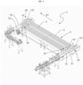
- number 1 denotes an apparatus for transferring and accumulating objects.
- the objects can be containers, such as bottles, dispensers, jars, cans.
- the objects can also be packages of products, e.g., powdered coffee or tea.
- the apparatus 1 comprises a plurality of accumulation channels 3.
- the plurality of accumulation channels 3 extends along an accumulation table 2.
- the accumulation channels 3 may be part of two or more flanked accumulation tables.
- the accumulation channels 3 each constitute an independent unit.
- Each accumulation channel 3 has an elongated extension between a loading end 3a and an unloading end 3b.
- the accumulation table 2 extends along an accumulation direction D1.
- the accumulation channels 3 extend along a plurality of directions parallel to each other and to the accumulation direction D1.
- the accumulation channels 3 are flanked to each other according to a direction which is orthogonal to the accumulation direction D1 and which, in this context, is indicated as the "flanking direction" of the accumulation channels 3.
- a flanking direction is indicated in the figures with D2.
- the apparatus 1 comprises at least a first transfer device 10 and a second transfer device 20 of the objects to the accumulation channels 3.
- the first and the second transfer device 10, 20 are arranged upstream of the accumulation channels 3.
- the first transfer device 10 comprises a first lane 11 and a first movable portion 12 associated with the first lane 11 for transferring objects therefrom to one of the accumulation channels 3.
- the first movable portion 12 is movable, in particular sliding, along the first lane 11 so as to be able to be arranged at the loading end 3a of the various accumulation channels 3.
- the first lane 11 may be made in a single piece or it may comprise multiple segments arranged one after the other so as to define such a first lane 11.
- the second transfer device 20 comprises a second lane 21 and a second movable portion 22 associated with the second lane 21 for transferring objects therefrom to one of the accumulation channels 3.
- the second movable portion 22 is movable, in particular sliding, along the second lane 21 so as to be able to be arranged at the loading end 3a of the various accumulation channels 3.
- the second lane 21 may be made in a single piece or it may comprise multiple segments arranged one after the other so as to define such a second lane 21.
- the first movable portion 12 comprises a first loading guide 13 which may be arranged at the loading end 3a of one of the accumulation channels 3 to guide the objects therein.
- the first movable portion 12 further comprises a first carriage (not illustrated) associated with the first loading guide 13 to move it along the first lane 11.
- the second movable portion 22 comprises a second loading guide 23 which may be arranged at the loading end 3a of one of the accumulation channels 3 to guide the objects therein.
- the second movable portion 22 further comprises a second carriage (not illustrated) associated with the second loading guide 23 to move it along the second lane 21.
- first and the second loading guide 13, 23 are motorized.
- Each movable portion 12, 22 is arranged and shaped so as to communicate with one of the accumulation channels 3 at a time.
- the second movable portion 22 cannot simultaneously be at the predefined accumulation channel 3.
- the second movable portion 22 could instead be, at such a same instant, at the loading end 3a of another accumulation channel 3, different from the predefined accumulation channel 3.
- the first lane 11 and the second lane 21 have an elongated extension in two substantially parallel directions, which are the object transport directions.
- the extension directions of the two lanes 11, 21 are transverse to the directions of the accumulation channels 3. Therefore, the extension directions of the two lanes 11, 21 are transverse to the accumulation direction D1.
- the extension directions of the two lanes 11, 21 are substantially orthogonal to the directions of the accumulation channels 3. Therefore, the extension directions of the two lanes 11, 21 are orthogonal to the accumulation direction D1.
- extension directions of the two lanes 11, 21 are substantially parallel to the flanking direction D2 of the accumulation channels 3.
- the accumulation table 2 consists of at least two groups of accumulation channels 3, hereinafter referred to as "first group” and "second group”.
- the first transfer device 10 is configured to transfer objects only to accumulation channels 3 of the first group, while the second transfer device 20 is configured to transfer objects only to accumulation channels 3 of the second group.
- the loading ends 3a of the accumulation channels 3 of the first group face the first lane 11 and the loading ends 3a of the accumulation channels 3 of the second group face the second lane 21.
- the first movable portion 12 by sliding along the first lane 11, can be arranged at the loading end 3a of one of the accumulation channels 3 of the first group.
- the second movable portion 22, by sliding along the second lane 21, can be arranged at the loading end 3a of one of the accumulation channels 3 of the second group.
- the accumulation channels 3 of the first group have the loading ends 3a aligned with each other, i.e., arranged along a first direction g1 which is parallel to the flanking direction D2.
- the accumulation channels 3 of the second group have the loading ends 3a aligned with each other, i.e., arranged along a second direction g2 which is parallel to the flanking direction D2.
- the loading ends 3a of the accumulation channels 3 of the first group are misaligned (i.e., offset) with respect to the loading ends 3a of the accumulation channels 3 of the second group.
- first direction g1 and the second direction g2 are parallel but spaced apart.
- the first alignment direction g1 of the loading ends 3a of the first group extends upstream of the second alignment direction g2 of the loading ends 3a of the second group, with respect to the accumulation direction D1.
- the loading ends 3a of the accumulation channels 3 of the first group are retracted with respect to the loading ends 3a of the accumulation channels 3 of the second group, with reference to the accumulation direction D1.
- the first transfer device 10 is at the service of the first group of accumulation channels 3, while the second transfer device 20 is at the service of the second group of accumulation channels 3.
- the first lane 11 is external with respect to the second lane 21.
- the second lane 21 extends over a shorter length with respect to the first lane 11.
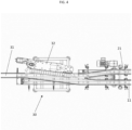
- both the first loading guide 13 and the second loading guide 23 have at least one curvilinear section 131, 231 for delivering the objects to the accumulation channel 3.
- the two curvilinear sections 131, 231 have counter-shaped surfaces so that, in a configuration of proximity between the first loading guide 13 and the second loading guide 23, such counter-shaped surfaces can come into contact.
- each curvilinear section 131, 231 comprises a passage channel 16 for the objects having an extension following the curvilinear profile of the curvilinear section 131, 231.
- each passage channel 16 is laterally delimited by a pair of motorized belts 17.
- each belt 17 of the pair defines a lateral abutment for the objects in transit.
- the belts 17 act laterally on the objects in transit in the loading guide 13, 23, providing them with the necessary thrust to continue their path towards the corresponding accumulation channel 3.
- the presence of the belts 17 allows to maintain the orientation even of objects shaped in a non-symmetrical manner, which could rotate if pushed only by the loading lane 11, 21.
- each passage channel 16 has a width which is adjustable as a function of the format of the objects.
- the distance between the pair of belts 17 is adjustable so as to adjust the width of the passage channel 16.
- the apparatus 1 is easily adaptable to the format change of the objects to be transferred.
- the apparatus 1 comprises means for feeding 30 the objects to the transfer devices 10, 20. Therefore, the feeding means 30 is arranged upstream of the transfer devices 10, 20.
- the feeding means 30 is configured to communicate in turn, i.e., alternatively, with the first and the second transfer device 10, 20.
- the feeding means 30 comprises a single-row conveyor belt 31, in which the objects advance one after the other in a single row, and an alternative divider 32 configured to enable in turn, i.e., alternatively, the communication between the single-row conveyor belt 31 and one of the two transfer devices 10, 20.
- the second transfer device 20 can in no way receive objects from the conveyor belt 31. That is, the communication established by the divider 32 is exclusive.
- the first transfer device 10 then selectively communicates upstream with the conveyor belt 31 and downstream with one of the accumulation channels 3.
- the apparatus 1 has been described so far. However, it is understood that the apparatus 1 may also comprise a greater number of transfer devices, as the operating logic does not change.
- the single-row conveyor belt 31 always communicates with only one transfer device at a time and communicates with all of them in turns. What was just described on the exclusive operating logic generally applies to the feeding means 30 and not only in the particular embodiment with a single-row conveyor belt 31 and a divider 32.
- the apparatus 1 comprises a control unit (not illustrated) configured to count the objects transferred from the single-row conveyor belt 31.
- the control unit is also configured, upon reaching a predetermined number of objects transferred towards one of the transfer devices 10, 20, to operate the divider 32 so as to impose an operating condition on the first transfer device 10, in which a flow of objects slides thereon and simultaneously impose a resting condition on the second transfer device 20, in which the flow of objects is blocked (i.e., does not slide thereon), or vice versa.
- the first and/or the second movable portion 12, 22 are moved along the relative lane 11, 21 from one accumulation channel 3 to another only during the resting condition thereof. It is thereby possible to sort the flow of objects without flow interruptions, passing from a (full) channel to a new channel to start filling.
- the transfer device 10, 20 which is in the resting condition has all the time to move at another channel without having to interrupt the flow of objects, which are diverted by the other transfer device 10, 20 in the operating condition on the corresponding channel.
- the resting condition of a transfer device 10, 20 is not dead time, but time during which the transfer of objects occurs by means of another transfer device 10, 20.
- the divider 32 is configured to interrupt the communication between the single-row conveyor belt 31 and the first transfer device 10 and enable the communication thereof with the second transfer device 20, upon reaching a predetermined number of objects transferred to the first transfer device 10. That is, the divider 32 is configured to divert the flow of objects towards the other transfer device 10, 20.
- "Other transfer device” herein means the transfer device 10, 20 which is not receiving the flow of objects.
- the predetermined number of objects identifies a filled condition of an accumulation channel 3. That is, once the first transfer device 10 has received a sufficient number of objects to fill the accumulation channel 3 with which it is communicating downstream, the divider 32 prevents further objects from reaching the first transfer device 10, diverting them towards the second transfer device 20.
- the divider 32 comprises an abutment element movable between a first engagement position, in which it engages at least in part the first transfer device 10, and a second position, in which it is housed in a seat obtained in the divider 32.
- the abutment element in the first engagement position engages at least in part the first lane 11.
- the first lane 11 is entirely crossed by the abutment element.
- the divider 32 imposes the resting condition on the first transfer device 10 (which corresponds to the imposition of the operating condition on the second transfer device 20), bringing the abutment element from the second engagement position to the first engagement position.
- the divider 32 imposes the operating condition on the first transfer device 10 (which corresponds to the imposition of the resting condition on the second transfer device 20), bringing the abutment element from the first engagement position to the second engagement position.
- the abutment element has an engagement surface shaped so as to guide the flow of objects towards the second lane 21.
- dividers of known type can be used which allow the single-row conveyor belt 31 to communicate with only one transfer device 10, 20 at a time.
- the apparatus 1 comprises a first unloading device 40 and a second unloading device 50 of the objects from the accumulation channels 3.
- the first and the second unloading device 40, 50 are arranged downstream of the accumulation channels 3.
- the first unloading device 40 is configured to transfer objects only from the accumulation channels 3 of the first group, while the second unloading device 50 is configured to transfer objects only from the accumulation channels 3 of the second group.
- the first unloading device 40 comprises a third lane 41 and a third movable portion 42 associated with the third lane 41 for transferring the objects coming from one of the accumulation channels 3 thereto.
- the third movable portion 42 is movable, in particular sliding, along the third lane 41 so as to be able to be arranged at the unloading end 3b of the various accumulation channels 3.
- the third lane 41 may be made in a single piece or may comprise multiple segments arranged one after the other so as to define such a third lane 41.
- the second unloading device 50 comprises a fourth lane 51 and a fourth movable portion 52 associated with the fourth lane 51 for transferring the objects coming from one of the accumulation channels 3 thereto.
- the fourth movable portion 52 is movable, in particular sliding, along the fourth lane 51 so as to be able to be arranged at the unloading end 3b of the various accumulation channels 3.
- the fourth lane 51 may be made in a single piece or it may comprise multiple segments arranged one after the other so as to define such a fourth lane 51.
- Each movable portion 42, 52 is arranged and shaped so as to communicate with one of the accumulation channels 3 at a time.
- the unloading ends 3b of the accumulation channels 3 of the first group face the third lane 41 and the unloading ends 3b of the accumulation channels 3 of the second group face the fourth lane 51.
- the third movable portion 42 sliding along the third lane 41, can be arranged at the unloading end 3b of one of the accumulation channels 3 of the first group.
- the fourth movable portion 52 sliding along the fourth lane 51, can be arranged at the unloading end 3b of one of the accumulation channels 3 of the second group.
- the first and the second unloading device 40, 50 are controlled so that, when the first one is affected by a flow of objects in output from the accumulation channel 3 with which it is communicating, the second one can be moved at the next accumulation channel 3 which will be emptied, and vice versa.
- the accumulation channels 3 of the first group have the unloading ends 3b aligned with each other, i.e., arranged along a third direction g3 which is parallel to the flanking direction D2.
- the accumulation channels 3 of the second group have the unloading ends 3b aligned with each other, i.e., arranged along a fourth direction g4 which is parallel to the flanking direction D2.
- the unloading ends 3b of the accumulation channels 3 of the first group are misaligned (i.e., offset) with respect to the loading ends 3b of the accumulation channels 3 of the second group.
- the third direction g3 and the fourth direction g4 are parallel but spaced apart.
- the third alignment direction g3 of the unloading ends 3b of the first group extends downstream of the fourth alignment direction g4 of the unloading ends 3b of the second group, with respect to the accumulation direction D1.
- the unloading ends 3b of the accumulation channels 3 of the first group are advanced with respect to the unloading ends 3b of the accumulation channels 3 of the second group, with reference to the accumulation direction D1.
- the first unloading device 40 is at the service of the first group of accumulation channels 3, while the second unloading device 50 is at the service of the second group of accumulation channels 3.
- the third lane 41 is external with respect to the fourth lane 51.
- the fourth lane 51 extends over a shorter length with respect to the third lane 41.
- the accumulation channels 3 of the first group have a longer length than the accumulation channels 3 of the second group.
- the accumulation channels 3 of the first group and the second group may have substantially the same length, or those of the second group may have a shorter length than those of the first group.
- the movable portions 12, 22, 42, 52 of the transfer devices 10, 20 and the unloading devices 40, 50 are substantially the same.
- the apparatus 1 comprises a device for gathering 60 the objects on a single row.
- the gathering device 60 communicates upstream with the third and the fourth lane 41, 51.
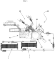
- the packaging line 80 (hereinafter briefly “line”) comprises an apparatus 1 for transferring and accumulating objects as described above.
- the line 80 further comprises a filling unit 82, followed by a closing unit 83.
- the line 80 further comprises a labelling unit 85.
- the filling unit 82 may comprise a filling machine or a dosing unit.
- the line 80 further comprises a blower 81 upstream of the filling unit 82.
- the closing unit 85 may be a capper or a capsule applying machine, as a function of the type of container.
- the line 80 comprises two apparatuses 1 arranged parallel.
- the line 80 comprises a flow dividing device 84 arranged downstream of the closing unit 83 and upstream of the apparatus 1.
- the flow of objects is shared on the two apparatuses 1, each of which operates according to the described logic. This solution is particularly suitable for high speeds.
- an apparatus 1 such as the one proposed can be arranged between the closing unit 83 and the labelling unit 85.
- the apparatus 1 is used in the embodiment with the gathering device 60 downstream.
- the line 80 further comprises a packaging machine or a cartoning machine (not shown) downstream of the apparatus 1.
- an apparatus 1 may be located between the labelling unit 85 and the packaging/cartoning machine.
- the apparatus 1 is used in the embodiment with two separate rows in output (as in figure 7 ).
- the presence of a motorized belt in the transfer channel allows to assist the objects in transit towards the accumulation channel.
- the provision of two lateral belts also allows to simultaneously guide and push the objects in transit towards the accumulation channel, preventing them from changing orientation.
- the width adjustability of the transfer channel increases the versatility of the apparatus, as it can be used in lines which include multiple object formats.
- the presence of more than one apparatus in the bottling line allows to manage even high speeds, without having to increase the accumulation channels present in an apparatus.
Landscapes
- Engineering & Computer Science (AREA)
- Mechanical Engineering (AREA)
- Attitude Control For Articles On Conveyors (AREA)
- Container Filling Or Packaging Operations (AREA)
Claims (14)
- Vorrichtung (1) zum Überführen und Ansammeln von Gegenständen, umfassend: mindestens eine erste Gruppe und eine zweite Gruppe von Sammelkanälen (3), die parallel zueinander verlaufen, wobei ein jeder Sammelkanal (3) eine längliche Erstreckung entlang einer Richtung parallel zu einer Sammelrichtung (D1) zwischen einem Ladeende (3a) und einem Entladeende (3b) von Gegenständen aufweist, wobei die Sammelkanäle (3) der ersten Gruppe die Ladeenden (3a), die miteinander ausgerichtet sind und die Entladeenden (3b), die miteinander ausgerichtet sind, aufweisen, wobei die Sammelkanäle (3) der zweiten Gruppe die Ladeenden (3a), die miteinander ausgerichtet sind und die Entladeenden (3b), die miteinander ausgerichtet sind, aufweisen;
mindestens eine erste und eine zweite Überführungsvorrichtung zum Überführen (10, 20) von Gegenständen zu den Sammelkanälen (3), wobei die erste Überführungsvorrichtung (10) ausgelegt ist, um Gegenstände nur zu Sammelkanälen (3) der ersten Gruppe zu überführen, wobei die zweite Überführungsvorrichtung (20) ausgelegt ist, um Gegenstände nur zu Sammelkanälen (3) der zweiten Gruppe zu überführen, wobei die erste und die zweite Überführungsvorrichtung (10, 20) am Eingang Gegenstände wiederum, d.h. alternativ, empfangen, dadurch gekennzeichnet, dass die Ladeenden (3a) der Sammelkanäle (3) der ersten Gruppe in Bezug auf die Ladeenden (3a) der Sammelkanäle (3) der zweiten Gruppe falsch ausgerichtet sind und dadurch, dass die Entladeenden (3b) der Sammelkanäle (3) der ersten Gruppe in Bezug auf die Entladeenden (3b) der Sammelkanäle (3) der zweiten Gruppe falsch ausgerichtet sind. - Vorrichtung (1) nach Anspruch 1, wobei die Sammelkanäle (3) der ersten Gruppe Ladeenden (3a) aufweisen, die entlang einer ersten Richtung (g1) angeordnet sind, die im Wesentlichen orthogonal zur Sammelrichtung (D1) verläuft und die Sammelkanäle (3) der zweiten Gruppe die Ladeenden (3a) aufweisen, die entlang einer zweiten Richtung (g2) angeordnet sind, die im Wesentlichen orthogonal zu der Sammelrichtung (D1) verläuft, wobei die erste Richtung (g1) und die zweite Richtung (d2) parallel, jedoch nicht zusammenfallend sind.
- Vorrichtung (1) nach Anspruch 2, wobei die erste Richtung (g1) in Bezug auf die zweite Richtung (g2) zurückgezogen ist.
- Vorrichtung (1) nach einem der vorhergehenden Ansprüche, wobei die mindestens eine erste und eine zweite Überführungsvorrichtung (10, 20) jeweils eine erste und eine zweite Spur (11, 21) und einen ersten und einen zweiten beweglichen Abschnitt (12, 22) umfassen, die jeweils mit der ersten und der zweiten Spur (11, 21) assoziiert sind, um die Gegenstände davon zu einem der Sammelkanäle (3) zu überführen.
- Vorrichtung (1) nach Anspruch 4, wobei ein jeder bewegliche Abschnitt (12, 22) mindestens eine krummlinige Sektion (131, 231) zum Übergeben der Gegenstände zu einem der Sammelkanäle (3) aufweist, wobei eine jede krummlinige Sektion (131, 231) einen Durchgangskanal (16) für die Gegenstände umfasst, der eine Erstreckung aufweist, die dem krummlinigen Profil der krummlinigen Sektion (131, 231) folgt.
- Vorrichtung (1) nach Anspruch 5, wobei ein jeder Durchgangskanal (16) seitlich durch ein Paar motorisierter Bänder (17) begrenzt ist.
- Vorrichtung (1) nach Anspruch 6, wobei der Abstand zwischen dem Paar von Bändern (17) einstellbar ist.
- Vorrichtung (1) nach einem der vorhergehenden Ansprüche, umfassend Mittel zum Zuführen (30) der Gegenstände zu der ersten und der zweiten Überführungsvorrichtung (10, 20), wobei die Zuführmittel (30) ausgelegt sind, um wiederum, d. h. alternativ, mit der ersten und der zweiten Überführungsvorrichtung (10, 20) zu kommunizieren.
- Vorrichtung (1) nach Anspruch 1, wobei die Sammelkanäle (3) der ersten Gruppe die Entladeenden (3b) aufweisen, die entlang einer dritten Richtung (g3) angeordnet sind, die im Wesentlichen orthogonal zu der Sammelrichtung (D1) verläuft, und die Sammelkanäle (3) der zweiten Gruppe die Entladeenden (3b) aufweisen, die entlang einer vierten Richtung (g4) angeordnet sind, die im Wesentlichen orthogonal zu der Sammelrichtung (D1) verläuft, wobei die dritte Richtung (g3) und die vierte Richtung (g4) parallel, jedoch nicht zusammenfallend sind.
- Vorrichtung (1) nach Anspruch 9, wobei die dritte Richtung (g3) in Bezug auf die vierte Richtung (g4) vorgeschoben wird.
- Vorrichtung (1) nach einem der vorhergehenden Ansprüche, umfassend mindestens eine erste und eine zweite Entladevorrichtung (40, 50) von Gegenständen aus den Sammelkanälen (3), wobei die erste Entladevorrichtung (40) ausgelegt ist, um Gegenstände nur aus den Sammelkanälen (3) der ersten Gruppe zu überführen, wobei die zweite Entladevorrichtung (50) ausgelegt ist, um Gegenstände nur aus den Sammelkanälen (3) der zweiten Gruppe zu überführen.
- Vorrichtung (1) nach einem der vorhergehenden Ansprüche, wobei die Sammelkanäle (3) der ersten Gruppe eine größere Länge als die Sammelkanäle (3) der zweiten Gruppe aufweisen.
- Verpackungslinie (80), umfassend:mindestens eine Vorrichtung (1) zum Überführen und Ansammeln von Gegenständen nach einem der vorhergehenden Ansprüche;eine Fülleinheit (82), eine Verschließeinheit (83) und eine Etikettiereinheit (85), wobei die zumindest eine Vorrichtung (1) zum Überführen und Ansammeln von Gegenständen stromabwärts der Verschließeinheit (83) angeordnet ist.
- Verpackungslinie (80) nach Anspruch 13, ferner umfassend eine Blaseinheit (81) stromaufwärts der Fülleinheit (82).
Priority Applications (8)
| Application Number | Priority Date | Filing Date | Title |
|---|---|---|---|
| EP22170517.1A EP4269294B1 (de) | 2022-04-28 | 2022-04-28 | Vorrichtung zum überführen und ansammeln von gegenständen und verpackungslinie mit dieser vorrichtung |
| ES22170517T ES2995023T3 (en) | 2022-04-28 | 2022-04-28 | Apparatus for transferring and accumulating objects and packaging line comprising said apparatus |
| PCT/IB2023/051544 WO2023209444A1 (en) | 2022-04-28 | 2023-02-20 | Apparatus for transferring and accumulating objects and packaging line comprising said apparatus |
| CA3210638A CA3210638A1 (en) | 2022-04-28 | 2023-02-20 | APPARATUS FOR TRANSFERRING AND ACCUMULATING OBJECTS, AND PACKAGING LINE INCLUDING THE APPARATUS |
| ES23710931T ES3060906T3 (en) | 2022-04-28 | 2023-02-20 | Apparatus for transferring and accumulating objects and packaging line comprising said apparatus |
| MX2023010363A MX2023010363A (es) | 2022-04-28 | 2023-02-20 | Aparato para transferir y acumular objetos, y linea de empacado que comprende dicho aparato. |
| EP23710931.9A EP4288360B1 (de) | 2022-04-28 | 2023-02-20 | Vorrichtung zum überführen und ansammeln von gegenständen und verpackungslinie mit dieser vorrichtung |
| US18/366,420 US12595137B2 (en) | 2022-04-28 | 2023-08-07 | Apparatus for transferring and accumulating objects and packaging line comprising said apparatus |
Applications Claiming Priority (1)
| Application Number | Priority Date | Filing Date | Title |
|---|---|---|---|
| EP22170517.1A EP4269294B1 (de) | 2022-04-28 | 2022-04-28 | Vorrichtung zum überführen und ansammeln von gegenständen und verpackungslinie mit dieser vorrichtung |
Publications (3)
| Publication Number | Publication Date |
|---|---|
| EP4269294A1 EP4269294A1 (de) | 2023-11-01 |
| EP4269294C0 EP4269294C0 (de) | 2024-08-28 |
| EP4269294B1 true EP4269294B1 (de) | 2024-08-28 |
Family
ID=82361274
Family Applications (2)
| Application Number | Title | Priority Date | Filing Date |
|---|---|---|---|
| EP22170517.1A Active EP4269294B1 (de) | 2022-04-28 | 2022-04-28 | Vorrichtung zum überführen und ansammeln von gegenständen und verpackungslinie mit dieser vorrichtung |
| EP23710931.9A Active EP4288360B1 (de) | 2022-04-28 | 2023-02-20 | Vorrichtung zum überführen und ansammeln von gegenständen und verpackungslinie mit dieser vorrichtung |
Family Applications After (1)
| Application Number | Title | Priority Date | Filing Date |
|---|---|---|---|
| EP23710931.9A Active EP4288360B1 (de) | 2022-04-28 | 2023-02-20 | Vorrichtung zum überführen und ansammeln von gegenständen und verpackungslinie mit dieser vorrichtung |
Country Status (6)
| Country | Link |
|---|---|
| US (1) | US12595137B2 (de) |
| EP (2) | EP4269294B1 (de) |
| CA (1) | CA3210638A1 (de) |
| ES (2) | ES2995023T3 (de) |
| MX (1) | MX2023010363A (de) |
| WO (1) | WO2023209444A1 (de) |
Families Citing this family (2)
| Publication number | Priority date | Publication date | Assignee | Title |
|---|---|---|---|---|
| DE102022109584A1 (de) * | 2022-04-20 | 2023-10-26 | Krones Aktiengesellschaft | Vorrichtung zum Zwischenspeichern und Fördern von Behältern zumindest in eine Förderrichtung |
| WO2026009089A1 (en) | 2024-07-01 | 2026-01-08 | Europool - S.R.L. | Apparatus and method for transferring and accumulating objects and packaging line comprising said apparatus |
Family Cites Families (11)
| Publication number | Priority date | Publication date | Assignee | Title |
|---|---|---|---|---|
| FR2689110B1 (fr) * | 1992-03-24 | 1998-04-17 | Sidel Sa | Machine de stockage de recipients entre une machine amont delivrant des recipients et une machine aval utilisatrice. |
| US6543600B2 (en) * | 2000-06-09 | 2003-04-08 | Ouellette Machinery Systems, Inc. | Early detection photo controls |
| DE10255814A1 (de) * | 2002-11-29 | 2004-06-09 | Khs Maschinen- Und Anlagenbau Ag, Patentabteilung | Vorrichtung zum Aufteilen und Auseinanderführen eines Behälterstromes |
| FR2988709A1 (fr) * | 2012-03-30 | 2013-10-04 | Sidel Participations | Systeme d'accumulation multivoies |
| FR3004172B1 (fr) | 2012-11-16 | 2017-12-22 | Sidel Participations | Dispositif et procede d'accumulation et de transfert |
| NL2010932C2 (en) * | 2013-06-07 | 2014-12-09 | Polyketting Holding B V | Gripping element suitable for use with an accumulator table, accumulator table provided with such a gripping element and conveyor system comprising such an accumulator table. |
| NL2013820B1 (en) | 2014-11-17 | 2016-10-10 | Polyketting Holding B V | Accumulator device for dynamically accumulating conveyed products, as well as a method for using such a device. |
| SE1750580A1 (en) * | 2017-05-11 | 2018-11-12 | Fredriksons Verkst Ab | Conveyor system and guiding system for guiding goods in a conveyor system |
| DE102017211901A1 (de) * | 2017-07-12 | 2019-01-17 | Krones Aktiengesellschaft | Zeilenpuffertisch |
| IT201900018494A1 (it) * | 2019-10-10 | 2021-04-10 | Ems Group S P A | Accumulatore con apparato deviatore per accumulo articoli |
| DE102022109584A1 (de) * | 2022-04-20 | 2023-10-26 | Krones Aktiengesellschaft | Vorrichtung zum Zwischenspeichern und Fördern von Behältern zumindest in eine Förderrichtung |
-
2022
- 2022-04-28 ES ES22170517T patent/ES2995023T3/es active Active
- 2022-04-28 EP EP22170517.1A patent/EP4269294B1/de active Active
-
2023
- 2023-02-20 CA CA3210638A patent/CA3210638A1/en active Pending
- 2023-02-20 MX MX2023010363A patent/MX2023010363A/es unknown
- 2023-02-20 WO PCT/IB2023/051544 patent/WO2023209444A1/en not_active Ceased
- 2023-02-20 EP EP23710931.9A patent/EP4288360B1/de active Active
- 2023-02-20 ES ES23710931T patent/ES3060906T3/es active Active
- 2023-08-07 US US18/366,420 patent/US12595137B2/en active Active
Also Published As
| Publication number | Publication date |
|---|---|
| US12595137B2 (en) | 2026-04-07 |
| WO2023209444A1 (en) | 2023-11-02 |
| EP4269294A1 (de) | 2023-11-01 |
| MX2023010363A (es) | 2023-11-13 |
| EP4269294C0 (de) | 2024-08-28 |
| CA3210638A1 (en) | 2025-01-20 |
| ES2995023T3 (en) | 2025-02-05 |
| EP4288360B1 (de) | 2025-12-03 |
| EP4288360A1 (de) | 2023-12-13 |
| ES3060906T3 (en) | 2026-03-30 |
| EP4288360C0 (de) | 2025-12-03 |
| US20240010443A1 (en) | 2024-01-11 |
Similar Documents
| Publication | Publication Date | Title |
|---|---|---|
| CN104271492B (zh) | 用于容器的灌装设备和操作该灌装设备的方法 | |
| US8544631B2 (en) | Apparatus and method for distributing articles within a stream of articles | |
| US10934103B2 (en) | Conveying storage device and method for operating the conveying storage device | |
| EP4288360B1 (de) | Vorrichtung zum überführen und ansammeln von gegenständen und verpackungslinie mit dieser vorrichtung | |
| CN113905961A (zh) | 用于分配和/或分组容器的方法和装置 | |
| EP4041662B1 (de) | Sammler mit umlenkvorrichtung zum sammeln von gegenständen | |
| US7775344B2 (en) | Device for buffering products and a method of operating this | |
| US5502950A (en) | Packaging machine with metering wheels | |
| WO2022136965A1 (en) | Device and method for transferring and accumulating objects | |
| US12297052B2 (en) | Transfer device for an apparatus for continuously conveying items, and method for continuously conveying items | |
| WO2002004327A2 (en) | A head for transferring containers, in particular bottles, within a palletiser | |
| EP4674792A1 (de) | Vorrichtung und verfahren zum überführen und sammeln von gegenständen und verpackungslinie mit dieser vorrichtung | |
| WO2026009089A1 (en) | Apparatus and method for transferring and accumulating objects and packaging line comprising said apparatus | |
| EP3983330B1 (de) | Anlage mit füllvorrichtung | |
| EP4592220A1 (de) | Vorrichtung und verfahren zum überführen und sammeln von gegenständen und verpackungslinie mit dieser vorrichtung | |
| CN121292030A (zh) | 用于运输具有运输道岔的单件货物的装置及方法 |
Legal Events
| Date | Code | Title | Description |
|---|---|---|---|
| PUAI | Public reference made under article 153(3) epc to a published international application that has entered the european phase |
Free format text: ORIGINAL CODE: 0009012 |
|
| STAA | Information on the status of an ep patent application or granted ep patent |
Free format text: STATUS: REQUEST FOR EXAMINATION WAS MADE |
|
| 17P | Request for examination filed |
Effective date: 20221221 |
|
| AK | Designated contracting states |
Kind code of ref document: A1 Designated state(s): AL AT BE BG CH CY CZ DE DK EE ES FI FR GB GR HR HU IE IS IT LI LT LU LV MC MK MT NL NO PL PT RO RS SE SI SK SM TR |
|
| P01 | Opt-out of the competence of the unified patent court (upc) registered |
Effective date: 20240229 |
|
| GRAP | Despatch of communication of intention to grant a patent |
Free format text: ORIGINAL CODE: EPIDOSNIGR1 |
|
| STAA | Information on the status of an ep patent application or granted ep patent |
Free format text: STATUS: GRANT OF PATENT IS INTENDED |
|
| INTG | Intention to grant announced |
Effective date: 20240610 |
|
| GRAS | Grant fee paid |
Free format text: ORIGINAL CODE: EPIDOSNIGR3 |
|
| GRAA | (expected) grant |
Free format text: ORIGINAL CODE: 0009210 |
|
| STAA | Information on the status of an ep patent application or granted ep patent |
Free format text: STATUS: THE PATENT HAS BEEN GRANTED |
|
| AK | Designated contracting states |
Kind code of ref document: B1 Designated state(s): AL AT BE BG CH CY CZ DE DK EE ES FI FR GB GR HR HU IE IS IT LI LT LU LV MC MK MT NL NO PL PT RO RS SE SI SK SM TR |
|
| REG | Reference to a national code |
Ref country code: CH Ref legal event code: EP |
|
| REG | Reference to a national code |
Ref country code: DE Ref legal event code: R096 Ref document number: 602022005595 Country of ref document: DE |
|
| REG | Reference to a national code |
Ref country code: IE Ref legal event code: FG4D |
|
| U01 | Request for unitary effect filed |
Effective date: 20240912 |
|
| U07 | Unitary effect registered |
Designated state(s): AT BE BG DE DK EE FI FR IT LT LU LV MT NL PT RO SE SI Effective date: 20241004 |
|
| P04 | Withdrawal of opt-out of the competence of the unified patent court (upc) registered |
Free format text: CASE NUMBER: APP_54061/2024 Effective date: 20240930 |
|
| P05 | Withdrawal of opt-out of the competence of the unified patent court (upc) changed |
Free format text: CASE NUMBER: APP_54061/2024 Effective date: 20241004 |
|
| PG25 | Lapsed in a contracting state [announced via postgrant information from national office to epo] |
Ref country code: NO Free format text: LAPSE BECAUSE OF FAILURE TO SUBMIT A TRANSLATION OF THE DESCRIPTION OR TO PAY THE FEE WITHIN THE PRESCRIBED TIME-LIMIT Effective date: 20241128 |
|
| PG25 | Lapsed in a contracting state [announced via postgrant information from national office to epo] |
Ref country code: PL Free format text: LAPSE BECAUSE OF FAILURE TO SUBMIT A TRANSLATION OF THE DESCRIPTION OR TO PAY THE FEE WITHIN THE PRESCRIBED TIME-LIMIT Effective date: 20240828 Ref country code: GR Free format text: LAPSE BECAUSE OF FAILURE TO SUBMIT A TRANSLATION OF THE DESCRIPTION OR TO PAY THE FEE WITHIN THE PRESCRIBED TIME-LIMIT Effective date: 20241129 |
|
| PG25 | Lapsed in a contracting state [announced via postgrant information from national office to epo] |
Ref country code: IS Free format text: LAPSE BECAUSE OF FAILURE TO SUBMIT A TRANSLATION OF THE DESCRIPTION OR TO PAY THE FEE WITHIN THE PRESCRIBED TIME-LIMIT Effective date: 20241228 |
|
| PG25 | Lapsed in a contracting state [announced via postgrant information from national office to epo] |
Ref country code: HR Free format text: LAPSE BECAUSE OF FAILURE TO SUBMIT A TRANSLATION OF THE DESCRIPTION OR TO PAY THE FEE WITHIN THE PRESCRIBED TIME-LIMIT Effective date: 20240828 |
|
| PG25 | Lapsed in a contracting state [announced via postgrant information from national office to epo] |
Ref country code: RS Free format text: LAPSE BECAUSE OF FAILURE TO SUBMIT A TRANSLATION OF THE DESCRIPTION OR TO PAY THE FEE WITHIN THE PRESCRIBED TIME-LIMIT Effective date: 20241128 |
|
| PG25 | Lapsed in a contracting state [announced via postgrant information from national office to epo] |
Ref country code: RS Free format text: LAPSE BECAUSE OF FAILURE TO SUBMIT A TRANSLATION OF THE DESCRIPTION OR TO PAY THE FEE WITHIN THE PRESCRIBED TIME-LIMIT Effective date: 20241128 Ref country code: PL Free format text: LAPSE BECAUSE OF FAILURE TO SUBMIT A TRANSLATION OF THE DESCRIPTION OR TO PAY THE FEE WITHIN THE PRESCRIBED TIME-LIMIT Effective date: 20240828 Ref country code: NO Free format text: LAPSE BECAUSE OF FAILURE TO SUBMIT A TRANSLATION OF THE DESCRIPTION OR TO PAY THE FEE WITHIN THE PRESCRIBED TIME-LIMIT Effective date: 20241128 Ref country code: IS Free format text: LAPSE BECAUSE OF FAILURE TO SUBMIT A TRANSLATION OF THE DESCRIPTION OR TO PAY THE FEE WITHIN THE PRESCRIBED TIME-LIMIT Effective date: 20241228 Ref country code: HR Free format text: LAPSE BECAUSE OF FAILURE TO SUBMIT A TRANSLATION OF THE DESCRIPTION OR TO PAY THE FEE WITHIN THE PRESCRIBED TIME-LIMIT Effective date: 20240828 Ref country code: GR Free format text: LAPSE BECAUSE OF FAILURE TO SUBMIT A TRANSLATION OF THE DESCRIPTION OR TO PAY THE FEE WITHIN THE PRESCRIBED TIME-LIMIT Effective date: 20241129 |
|
| REG | Reference to a national code |
Ref country code: ES Ref legal event code: FG2A Ref document number: 2995023 Country of ref document: ES Kind code of ref document: T3 Effective date: 20250205 |
|
| PG25 | Lapsed in a contracting state [announced via postgrant information from national office to epo] |
Ref country code: SM Free format text: LAPSE BECAUSE OF FAILURE TO SUBMIT A TRANSLATION OF THE DESCRIPTION OR TO PAY THE FEE WITHIN THE PRESCRIBED TIME-LIMIT Effective date: 20240828 |
|
| PG25 | Lapsed in a contracting state [announced via postgrant information from national office to epo] |
Ref country code: CZ Free format text: LAPSE BECAUSE OF FAILURE TO SUBMIT A TRANSLATION OF THE DESCRIPTION OR TO PAY THE FEE WITHIN THE PRESCRIBED TIME-LIMIT Effective date: 20240828 |
|
| PG25 | Lapsed in a contracting state [announced via postgrant information from national office to epo] |
Ref country code: SK Free format text: LAPSE BECAUSE OF FAILURE TO SUBMIT A TRANSLATION OF THE DESCRIPTION OR TO PAY THE FEE WITHIN THE PRESCRIBED TIME-LIMIT Effective date: 20240828 |
|
| U20 | Renewal fee for the european patent with unitary effect paid |
Year of fee payment: 4 Effective date: 20250429 |
|
| PLBE | No opposition filed within time limit |
Free format text: ORIGINAL CODE: 0009261 |
|
| STAA | Information on the status of an ep patent application or granted ep patent |
Free format text: STATUS: NO OPPOSITION FILED WITHIN TIME LIMIT |
|
| PGFP | Annual fee paid to national office [announced via postgrant information from national office to epo] |
Ref country code: ES Payment date: 20250513 Year of fee payment: 4 |
|
| 26N | No opposition filed |
Effective date: 20250530 |
|
| REG | Reference to a national code |
Ref country code: CH Ref legal event code: H13 Free format text: ST27 STATUS EVENT CODE: U-0-0-H10-H13 (AS PROVIDED BY THE NATIONAL OFFICE) Effective date: 20251125 |
|
| PG25 | Lapsed in a contracting state [announced via postgrant information from national office to epo] |
Ref country code: MC Free format text: LAPSE BECAUSE OF FAILURE TO SUBMIT A TRANSLATION OF THE DESCRIPTION OR TO PAY THE FEE WITHIN THE PRESCRIBED TIME-LIMIT Effective date: 20240828 |
|
| PG25 | Lapsed in a contracting state [announced via postgrant information from national office to epo] |
Ref country code: CH Free format text: LAPSE BECAUSE OF NON-PAYMENT OF DUE FEES Effective date: 20250430 |
|
| PGFP | Annual fee paid to national office [announced via postgrant information from national office to epo] |
Ref country code: GB Payment date: 20260319 Year of fee payment: 5 |
|
| PG25 | Lapsed in a contracting state [announced via postgrant information from national office to epo] |
Ref country code: IE Free format text: LAPSE BECAUSE OF NON-PAYMENT OF DUE FEES Effective date: 20250428 |