EP3983330B1 - Anlage mit füllvorrichtung - Google Patents
Anlage mit füllvorrichtung Download PDFInfo
- Publication number
- EP3983330B1 EP3983330B1 EP20730611.9A EP20730611A EP3983330B1 EP 3983330 B1 EP3983330 B1 EP 3983330B1 EP 20730611 A EP20730611 A EP 20730611A EP 3983330 B1 EP3983330 B1 EP 3983330B1
- Authority
- EP
- European Patent Office
- Prior art keywords
- advancement
- machine
- vessels
- processed
- bottling
- Prior art date
- Legal status (The legal status is an assumption and is not a legal conclusion. Google has not performed a legal analysis and makes no representation as to the accuracy of the status listed.)
- Active
Links
Images






Classifications
-
- B—PERFORMING OPERATIONS; TRANSPORTING
- B67—OPENING, CLOSING OR CLEANING BOTTLES, JARS OR SIMILAR CONTAINERS; LIQUID HANDLING
- B67C—CLEANING, FILLING WITH LIQUIDS OR SEMILIQUIDS, OR EMPTYING, OF BOTTLES, JARS, CANS, CASKS, BARRELS, OR SIMILAR CONTAINERS, NOT OTHERWISE PROVIDED FOR; FUNNELS
- B67C7/00—Concurrent cleaning, filling, and closing of bottles; Processes or devices for at least two of these operations
- B67C7/0006—Conveying; Synchronising
- B67C7/0026—Conveying; Synchronising the containers travelling along a linear path
-
- B—PERFORMING OPERATIONS; TRANSPORTING
- B67—OPENING, CLOSING OR CLEANING BOTTLES, JARS OR SIMILAR CONTAINERS; LIQUID HANDLING
- B67C—CLEANING, FILLING WITH LIQUIDS OR SEMILIQUIDS, OR EMPTYING, OF BOTTLES, JARS, CANS, CASKS, BARRELS, OR SIMILAR CONTAINERS, NOT OTHERWISE PROVIDED FOR; FUNNELS
- B67C3/00—Bottling liquids or semiliquids; Filling jars or cans with liquids or semiliquids using bottling or like apparatus; Filling casks or barrels with liquids or semiliquids
- B67C3/02—Bottling liquids or semiliquids; Filling jars or cans with liquids or semiliquids using bottling or like apparatus
- B67C3/22—Details
- B67C3/225—Means for filling simultaneously, e.g. in a rotary filling apparatus or multiple rows of containers
-
- B—PERFORMING OPERATIONS; TRANSPORTING
- B65—CONVEYING; PACKING; STORING; HANDLING THIN OR FILAMENTARY MATERIAL
- B65G—TRANSPORT OR STORAGE DEVICES, e.g. CONVEYORS FOR LOADING OR TIPPING, SHOP CONVEYOR SYSTEMS OR PNEUMATIC TUBE CONVEYORS
- B65G33/00—Screw or rotary spiral conveyors
- B65G33/02—Screw or rotary spiral conveyors for articles
- B65G33/04—Screw or rotary spiral conveyors for articles conveyed between a single screw and guiding means
-
- B—PERFORMING OPERATIONS; TRANSPORTING
- B65—CONVEYING; PACKING; STORING; HANDLING THIN OR FILAMENTARY MATERIAL
- B65G—TRANSPORT OR STORAGE DEVICES, e.g. CONVEYORS FOR LOADING OR TIPPING, SHOP CONVEYOR SYSTEMS OR PNEUMATIC TUBE CONVEYORS
- B65G33/00—Screw or rotary spiral conveyors
- B65G33/02—Screw or rotary spiral conveyors for articles
- B65G33/06—Screw or rotary spiral conveyors for articles conveyed and guided by parallel screws
Definitions
- the present invention relates to a machine, particularly of the type with increased productivity.
- these are conveyor belts on which the vessels are arranged upright and, by virtue of adapted spacer means, allow to obtain the row mentioned above.
- the obtainable pitch varies according to the specifications of the machine and to the nature of the spacer means chosen.
- the pitch can be defined by the dimensions of the vessels themselves, since they are arranged in a row one against the other, or by means of adapted handling devices.
- bottling machines of a known type since they have to ensure a preset hourly production, comprise bottling assemblies constituted by a battery of filling nozzles such as to allow the processing of multiple vessels at the same time.
- such filling nozzles are mutually aligned along and above a portion of the advancement line with a pitch that coincides with the pitch of the underlying vessels, and when the group of vessels to be filled arrives they fill them simultaneously.
- bottling machines of the rotary type which might contain the space occupation of the machine but would lead to an extremely rigid system in terms of format change, making it almost inapplicable, all at a higher cost than bottling machines of the linear type.
- the aim of the present invention is to provide a bottling machine that allows to have an increased productivity with respect to machines of a known type with limited space occupation.
- an object of the present invention is to provide a bottling machine in which it is possible to perform a change of format simply and rapidly.
- Another object of the present invention is to provide a bottling machine that allows easy and straightforward interventions by the operator.
- Another object of the present invention is to provide a bottling machine that has production costs comparable with machines of a known type.
- Another object of the present invention is to provide a bottling machine that offers the greatest assurances of reliability and efficiency.
- a machine comprising at least one advancement assembly which operates along an advancement line and at least one processing station crossed by said advancement line and comprising at least one bottling assembly; characterized in that said at least one bottling assembly comprises at least two lateral batteries of filling nozzles arranged respectively above at least two advancement channels of vessels to be processed, which are organized in two mutually parallel rows and with said filling nozzles mutually spaced so as to be arranged at the vertical projection of said vessels to be processed.
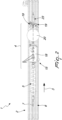
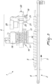
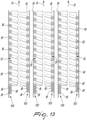
- the machine particularly of the type with increased productivity, which in the present embodiment is of the bottling machine type, is generally designated by the reference numeral 1 and comprises at least one advancement assembly 2 which operates along an advancement line 3 and at least one processing station 4 crossed by the advancement line 3.
- the advancement assembly 2 comprises a number "n” of screw feeders 5 comprised between 1 and “m” arranged on a working surface 6 and able to rotate about their respective longitudinal axis 7 which is arranged substantially parallel to the working surface 6 and to the advancement line 3.
- each screw feeder 5 is extended from a station for picking up vessels to be processed 8, not shown for the sake of graphic convenience and since it is per se known, which is located upstream of said screw feeder 5 at least up to the processing station 4.
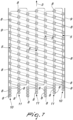
- guiding strips 9 of the type that is transversely adjustable with respect to the longitudinal axis 7 are further comprised and are extended parallel to the advancement line 3 and substantially at right angles to the working surface 6 oppositely with respect to the screw feeders 5 for the definition of a plurality of external advancement channels 10 of the vessels to be processed 8 which are delimited by each guiding strip 9 and by the adjacent screw feeder 5 so that the vessels to be processed 8 can be trapped upright on the working surface 6 between two consecutive crests of the screw feeder 5 and the adjacent guiding strip 9.
- this can comprise a plurality of screw feeders 5 which are mutually laterally adjacent in order to define a plurality of internal advancement channels 11 of the vessels to be processed 8 which are delimited by each pair of screw feeders 5 so that the vessels to be processed 8 can be trapped upright on the working surface 6 between two first consecutive crests 12 of a first screw feeder 5 and two second consecutive crests 13, which are opposite with respect to the first consecutive crests 12, of a second screw feeder 5 which is adjacent to the first screw feeder 5.
- the screw feeders 5 have the same pitch and are mutually synchronous in rotation.
- the vessels to be processed 8 can advance along said advancement line 3, upright on the working surface 6, following the rotation of the one or more screw feeders 5 about their respective longitudinal axis 7.
- the working surface 6 previously mentioned is constituted by a conveyor belt 14 which can move in a synchronous manner with the advancement speed of the vessels to be processed 8.
- said conveyor belt 14 is provided by a plurality of side-by-side and mutually synchronous conveyor belts.
- the machine 1 is of the bottling machine type and the vessels to be processed 8 are bottles for beverages such as beer and the like.
- vessels consist of: cans, jars, vials or containers in general for food products or non-food products such as: wine, oil, cider, liqueurs, spirits in general, creams, sauces, products for cosmetic use, products for pharmaceutical use, personal hygiene products and others.
- the processing station thus comprises at least one bottling assembly 15 comprising in turn, for each pair of advancement channels 10 and/or 11, at least two lateral batteries 16 of filling nozzles 17 arranged respectively above the two advancement channels 10 and/or 11 with the filling nozzles 17 mutually spaced so as to be arranged at the vertical projection of the vessels to be processed 8.
- the bottling assembly 15 is functionally connected to the two lateral batteries 16 and comprises a product tank 18 which feeds the filling nozzles 17 by means of adapted manifolds and electric valves.
- the bottling assembly 15 Arranged downstream of the filling nozzles 17 along the advancement line 3, the bottling assembly 15 comprises closure fitting devices 19 arranged respectively above the advancement channels 10 and/or 11 so as to be located at the vertical projection of the vessels to be processed 8 once they have been filled.
- the bottling assembly 15 is functionally connected to the closure fitting devices 19 and comprises a closure feeder 20.
- the bottling assembly 15 comprises at least two frothing nozzles 21 arranged between the two lateral batteries 16 and the closure fitting devices 19 along the advancement line 3.
- nozzles which are functionally connected to a water tank 22, are arranged respectively above the advancement channels 10 and/or 11 so as to be located at the vertical projection of the vessels to be processed 8 once they have been filled.
- a single supporting beam 23 which is arranged above and centrally with respect to the advancement channels 10 and/or 11 and which supports laterally at least one from the filling nozzles 17, the frothing nozzles 21 and the closure fitting devices 19 and centrally at least one from the product tank 18, the water tank 22 and the closure feeder 20.
- each lateral battery 16 are longitudinally offset, along the advancement line 3, with respect to the filling nozzles of the other opposite lateral battery 16 so that the actuation and supply components of each filling nozzle 17 of each lateral battery 16 are accommodated at least partly between two filling nozzles 17 which belong to the other opposite lateral battery 16.
- closure fitting devices 19 and the frothing nozzles 21 also can be offset with respect to their opposites.
- each screw feeder 5 can be divided into two portions with an independent speed, the first of which is extended up to the bottling assembly 15 included and the second is extended below the frothing nozzles 21 and the closure fitting devices 19.
- washing and rinsing devices which are per se known and therefore are not shown graphically, and are adapted to clean and rinse the vessels 8 during the filling and closure fitting process, or it is possible to provide any other device adapted to perform operations which are additional and/or alternative to those described so far, which are in any case comprised within the inventive concept of the present invention.
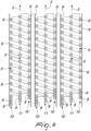
- the processing station can comprise a plurality of bottling assemblies 15 such as the one described above, arranged above an equal number of advancement lines 3.
- the machine can be designed by implementing a plurality of mutually parallel advancement lines 3 with an equal number of advancement assemblies 2 and bottling assemblies 3.
- the advancement assemblies 2 can comprise screw feeders 5 which, by virtue of guiding strips 9 or other screw feeders 5, define feeding channels 10 and/or 11 on both sides of the individual screw feeder 5 so as to double the transport capacity of the individual screw feeder 5 and, regardless of the constructive nature of the individual feeding assembly 2, the bottling assembly 15 allows to perform all the bottling steps by optimizing its lateral space occupations due to fewer components because they are common among different mutually offset lateral batteries 16 of filling nozzles 17.
- Another advantage of the machine according to the present invention resides in that the bottling assembly thus defined allows access by the operator from both sides without any space occupation of any kind. In fact, on the individual sides of the bottling assembly there is free access to the bottling nozzles of the relevant side and to the electrohydraulic components of the opposite side.
- the materials used, as well as the contingent shapes and dimensions may be any according to the requirements and the state of the art.
Landscapes
- Filling Of Jars Or Cans And Processes For Cleaning And Sealing Jars (AREA)
- Diaphragms For Electromechanical Transducers (AREA)
- Ignition Installations For Internal Combustion Engines (AREA)
- Non-Portable Lighting Devices Or Systems Thereof (AREA)
Claims (13)
- Eine Anlage (1), die mindestens einen Vorschubaufbau (2) umfasst, welcher entlang einer Vorschublinie (3) arbeitet, und mindestens eine Behandlungsstation (4), die von der Vorschublinie (3) durchquert wird und mindestens eine Füllvorrichtung (15) umfasst, wobei die mindestens eine Füllvorrichtung (15) mindestens zwei seitliche Sätze (16) von Füllstutzen (17) umfasst, jeweils angeordnet über mindestens zwei Vorschubkanälen (10, 11) zu behandelnder Gefäße (8), welche in zwei zueinander parallelen Reihen geordnet sind und wobei die Füllstutzen (17) voneinander beabstandet sind, um an der vertikalen Projektion der zu behandelnden Gefäße (8) angeordnet zu werden; wobei die Füllstutzen (17) jedes der mindestens zwei seitlichen Sätze (16) entlang der Vorschublinie (3) im Verhältnis zu den Füllstutzen des anderen der mindestens zwei seitlichen Sätze (16) in Längsrichtung versetzt sind; dadurch gekennzeichnet, dass die Betätigungs- und Versorgungskomponenten jedes der Füllstutzen (17) jedes der mindestens zwei seitlichen Sätze (16) zumindest teilweise zwischen zwei der Füllstutzen (17) angeordnet sind, die zu dem anderen der mindestens zwei seitlichen Sätze (16) gehören.
- Die Anlage (1) gemäß Anspruch 1, dadurch gekennzeichnet, dass sie vom Abfüllanlagentyp ist, und dadurch, dass die zu behandelnden Gefäße (8) Flaschen sind.
- Die Anlage (1) gemäß Anspruch 1 oder 2, dadurch gekennzeichnet, dass die mindestens zwei seitlichen Sätze (16) funktionell mit einem Produktbehälter (18) verbunden sind.
- Die Anlage (1) gemäß einem oder mehreren der obigen Ansprüche, dadurch gekennzeichnet, dass die Füllvorrichtung (15) Verschlussaufsetzvorrichtungen (19) umfasst, die sich entlang der Vorschublinie (3) stromabwärts von den Füllstutzen (17) befinden und jeweils über den Vorschubkanälen (10, 11) angeordnet sind, um an der vertikalen Projektion der zu behandelnden Gefäße (8) positioniert zu werden, sobald sie gefüllt wurden.
- Die Anlage (1) gemäß einem oder mehreren der obigen Ansprüche, dadurch gekennzeichnet, dass die Verschlussaufsetzvorrichtungen (19) funktionell mit einer Verschlusszuführvorrichtung (20) verbunden sind.
- Die Anlage (1) gemäß einem oder mehreren der obigen Ansprüche, dadurch gekennzeichnet, dass die Füllvorrichtung (15) mindestens zwei Schäumdüsen (21) umfasst, die zwischen den mindestens zwei seitlichen Sätzen (16) und den Verschlussaufsetzvorrichtungen (19) entlang der Vorschublinie (3) und oberhalb der Vorschubkanäle (10, 11) angeordnet sind, um an der vertikalen Projektion der zu behandelnden Gefäße (8) positioniert zu sein, sobald sie gefüllt wurden.
- Die Anlage (1) gemäß einem oder mehreren der obigen Ansprüche, dadurch gekennzeichnet, dass die Schäumdüsen (21) funktionell mit einem Wasserbehälter (22) verbunden sind.
- Die Anlage (1) gemäß einem oder mehreren der obigen Ansprüche, dadurch gekennzeichnet, dass sie einen einzigen Träger (23) umfasst, der oberhalb von und zentral mit Bezug auf die Vorschubkanäle (10, 11) angeordnet ist und seitlich mindestens eines der Füllstutzen (17), der Schäumdüsen (21) und der Verschlussaufsetzvorrichtungen (19) und in der Mitte mindestens eines von dem Produktbehälter (18), dem Wasserbehälter (22) und der Verschlusszuführvorrichtung (20) trägt.
- Die Anlage (1) gemäß einem oder mehreren der obigen Ansprüche, dadurch gekennzeichnet, dass die Behandlungsstation (4) eine Vielzahl der Füllvorrichtungen (15) umfasst.
- Die Maschine (1) gemäß einem oder mehreren der obigen Ansprüche, dadurch gekennzeichnet, dass der mindestens eine Vorschubaufbau (2) eine Anzahl n von Schneckenförderern (5) umfasst, die zwischen 1 und m beträgt, angeordnet auf einer Arbeitsfläche (6) und in der Lage, sich um ihre entsprechende Längsachse (7) zu drehen, welche im Wesentlichen parallel zu der Arbeitsfläche (6) und zu der Vorschublinie (3) angeordnet ist; wobei jeder der Schneckenförderer (5) sich von einer Station zum Aufnehmen zu behandelnder Gefäße (8), die sich stromaufwärts von dem Schneckenförderer (5) befindet, mindestens bis zu der Behandlungsstation (4) erstreckt; wobei weiter Führungsleisten (9) umfasst sind, die sich parallel zu der Vorschublinie (3) und im Wesentlichen in rechten Winkeln zu der Arbeitsfläche (6) den Schneckenförderern (5) gegenüber erstrecken, zur Bestimmung einer Vielzahl externer Vorschubkanäle (10) der zu behandelnden Gefäße (8), die durch jede der Führungsleisten (9) und durch den benachbarten Schneckenförderer (5) begrenzt sind, so dass die zu behandelnden Gefäße (8) aufrecht auf der Arbeitsfläche (6) zwischen zwei aufeinander folgenden Scheitelpunkten (12, 13) des Schneckenförderers (5) und der angrenzenden Führungsleiste (9) eingefangen werden und sich infolge der Drehung der Schneckenförderer (5) um die entsprechende Längsachse (7) entlang der Vorschublinie (3) vorwärts bewegen können.
- Die Anlage (1) gemäß Anspruch 9, dadurch gekennzeichnet, dass der Vorschubaufbau (2) eine Vielzahl der Schneckenförderer (5) umfasst, die seitlich aneinander angrenzen, um eine Vielzahl interner Vorschubkanäle (11) der zu behandelnden Gefäße (8) zu bestimmen, die durch jedes Paar der Schneckenförderer (5) begrenzt sind, so dass die zu behandelnden Gefäße (8) aufrecht auf der Arbeitsfläche (6) zwischen zwei ersten aufeinander folgenden Scheitelpunkten (12) eines ersten der Schneckenförderer (5) und zwei zweiten aufeinander folgenden Scheitelpunkten (13) eines zweiten Schneckenförderers (5), welcher an den ersten Schneckenförderer (5) angrenzt, eingefangen werden können, die den ersten aufeinander folgenden Scheitelpunkten (12) gegenüberliegen; wobei die Schneckenförderer (5) dieselbe Steigung haben und in der Drehung miteinander synchron sind.
- Die Anlage (1) gemäß Anspruch 9 oder 10, dadurch gekennzeichnet, dass die Arbeitsfläche (6) aus einem Förderband (14) besteht, welches sich synchron mit der Vorschubgeschwindigkeit der zu behandelnden Gefäße (8) bewegen kann.
- Die Anlage (1) gemäß einem oder mehreren der Ansprüche 9 bis 11, dadurch gekennzeichnet, dass sie eine Vielzahl der Vorschubaufbauten (2) umfasst, die entlang einer Vielzahl von Vorschublinien (3) arbeiten, welche durch die mindestens eine Behandlungsstation (4) verlaufen.
Applications Claiming Priority (2)
| Application Number | Priority Date | Filing Date | Title |
|---|---|---|---|
| IT102019000009117A IT201900009117A1 (it) | 2019-06-17 | 2019-06-17 | Macchina perfezionata, particolarmente del tipo a produttività incrementata. |
| PCT/EP2020/065382 WO2020254111A1 (en) | 2019-06-17 | 2020-06-03 | Machine, particularly of the type with increased productivity |
Publications (3)
| Publication Number | Publication Date |
|---|---|
| EP3983330A1 EP3983330A1 (de) | 2022-04-20 |
| EP3983330C0 EP3983330C0 (de) | 2024-09-18 |
| EP3983330B1 true EP3983330B1 (de) | 2024-09-18 |
Family
ID=68138710
Family Applications (1)
| Application Number | Title | Priority Date | Filing Date |
|---|---|---|---|
| EP20730611.9A Active EP3983330B1 (de) | 2019-06-17 | 2020-06-03 | Anlage mit füllvorrichtung |
Country Status (3)
| Country | Link |
|---|---|
| EP (1) | EP3983330B1 (de) |
| IT (1) | IT201900009117A1 (de) |
| WO (1) | WO2020254111A1 (de) |
Families Citing this family (1)
| Publication number | Priority date | Publication date | Assignee | Title |
|---|---|---|---|---|
| IT202200018285A1 (it) | 2022-09-08 | 2024-03-08 | Promec Srl A Fontevivo Pr | Apparecchiatura per il riempimento e la tappatura di contenitori per liquidi e relativo metodo |
Family Cites Families (9)
| Publication number | Priority date | Publication date | Assignee | Title |
|---|---|---|---|---|
| US4004620A (en) * | 1974-10-04 | 1977-01-25 | Sidney Rosen | Fluid filling machine |
| FR2589139B1 (fr) * | 1985-10-24 | 1988-04-15 | Saint Gobain Emballage | Conditionnement automatique dans des recipients |
| DE4135438A1 (de) * | 1991-10-26 | 1993-04-29 | Orthmann & Herbst | Vorrichtung zum aufschaeumen von karbonisierten getraenken in flaschen |
| AU7995900A (en) * | 1999-10-15 | 2001-04-30 | Hartness International, Inc. | Continuous circular motion case packing and depacking apparatus and method |
| DE102008032822A1 (de) * | 2008-07-11 | 2010-01-14 | Krones Ag | Vorrichtung zum Abfüllen von Getränken |
| WO2015071868A2 (en) * | 2013-11-15 | 2015-05-21 | Rejves S.R.L. | Apparatus for screw capping while in pursuit and working unit comprising said apparatus |
| US9862585B2 (en) * | 2016-05-27 | 2018-01-09 | Psr Automation, Inc. | Continuous motion linear container filler |
| CN107021444A (zh) * | 2017-05-24 | 2017-08-08 | 南京乐惠轻工装备制造有限公司 | 一种带气体保护的高压激泡喷嘴 |
| CN108439316A (zh) * | 2018-05-05 | 2018-08-24 | 杭州巧狮信息科技有限公司 | 一种食用调和油瓶装机 |
-
2019
- 2019-06-17 IT IT102019000009117A patent/IT201900009117A1/it unknown
-
2020
- 2020-06-03 EP EP20730611.9A patent/EP3983330B1/de active Active
- 2020-06-03 WO PCT/EP2020/065382 patent/WO2020254111A1/en not_active Ceased
Also Published As
| Publication number | Publication date |
|---|---|
| EP3983330C0 (de) | 2024-09-18 |
| IT201900009117A1 (it) | 2020-12-17 |
| WO2020254111A1 (en) | 2020-12-24 |
| EP3983330A1 (de) | 2022-04-20 |
Similar Documents
| Publication | Publication Date | Title |
|---|---|---|
| AU2009209009B2 (en) | Twin packaging line and metering system | |
| US5133446A (en) | Device for the formation and transfer of groups of commodities | |
| EP1539620B1 (de) | Verfahren und vorrichtung zur gruppierung von aseptischen produkten | |
| EP2471728A1 (de) | Anordnung mehrerer miteinander gekoppelter Behälterhandhabungs- und/oder Behälterbehandlungs- und/oder Behältertransportmodule sowie Verfahren zum Transport, zur Behandlung und/oder Handhabung von Behältern | |
| EP2460747B1 (de) | Vorrichtung und Verfahren zum Zuführen von Flaschen zu einer Füllstation | |
| EP3044096B1 (de) | Verpackungsmaschine und verfahren zur verpackung von artikeln | |
| EP3106397B1 (de) | Verpackungsgruppierungseinheit mit reduzierung der linearen verpackungsgeschwindigkeit | |
| EP3983330B1 (de) | Anlage mit füllvorrichtung | |
| US2857037A (en) | Container feeding mechanism | |
| EP4288360B1 (de) | Vorrichtung zum überführen und ansammeln von gegenständen und verpackungslinie mit dieser vorrichtung | |
| EP3064440B1 (de) | Produktverpackungseinheit für eine verpackungsstrasse | |
| US20100037981A1 (en) | Method and device for filling containers | |
| US5485713A (en) | Method and apparatus for inserting partitions into article groups | |
| US9849696B2 (en) | Printing on packaging material in multilane flow wrapping machine | |
| EP3106398A1 (de) | Verpackungsgruppierungseinheit mit reduzierung der linearen verpackungsgeschwindigkeit | |
| EP1924502B1 (de) | Maschine zum verpacken von artikeln | |
| CN214029304U (zh) | 推瓶机构及瓶子包装装置 | |
| CN202345952U (zh) | 一种输瓶装置 | |
| WO2007008445B1 (en) | Packaging method and apparatus for stacked articles | |
| DE102011007935A1 (de) | Anordnung mehrerer miteinander gekoppelter Behälterhandhabungs- und/oder Behälterbehandlungsmodule und Verfahren zum Transport, zur Behandlung und/oder Handhabung von Behältern | |
| EP4353673A1 (de) | Vorrichtung zum füllen und verschliessen von flüssigkeitsbehältern und entsprechendes verfahren ohne formatwechsel | |
| WO2026073550A1 (en) | Output wheel with double collecting wheel for a packaging machine | |
| IT201900009120A1 (it) | Macchina perfezionata, particolarmente del tipo a produttività incrementata. | |
| EP3141128A1 (de) | Hybrider keksfüller zur befüllung mit cremes mit verschiedener struktur | |
| CN214776870U (zh) | 一种过桥式下落装箱机 |
Legal Events
| Date | Code | Title | Description |
|---|---|---|---|
| STAA | Information on the status of an ep patent application or granted ep patent |
Free format text: STATUS: UNKNOWN |
|
| STAA | Information on the status of an ep patent application or granted ep patent |
Free format text: STATUS: THE INTERNATIONAL PUBLICATION HAS BEEN MADE |
|
| PUAI | Public reference made under article 153(3) epc to a published international application that has entered the european phase |
Free format text: ORIGINAL CODE: 0009012 |
|
| STAA | Information on the status of an ep patent application or granted ep patent |
Free format text: STATUS: REQUEST FOR EXAMINATION WAS MADE |
|
| 17P | Request for examination filed |
Effective date: 20211217 |
|
| AK | Designated contracting states |
Kind code of ref document: A1 Designated state(s): AL AT BE BG CH CY CZ DE DK EE ES FI FR GB GR HR HU IE IS IT LI LT LU LV MC MK MT NL NO PL PT RO RS SE SI SK SM TR |
|
| DAV | Request for validation of the european patent (deleted) | ||
| DAX | Request for extension of the european patent (deleted) | ||
| P01 | Opt-out of the competence of the unified patent court (upc) registered |
Effective date: 20230526 |
|
| GRAP | Despatch of communication of intention to grant a patent |
Free format text: ORIGINAL CODE: EPIDOSNIGR1 |
|
| STAA | Information on the status of an ep patent application or granted ep patent |
Free format text: STATUS: GRANT OF PATENT IS INTENDED |
|
| INTG | Intention to grant announced |
Effective date: 20240418 |
|
| GRAS | Grant fee paid |
Free format text: ORIGINAL CODE: EPIDOSNIGR3 |
|
| GRAA | (expected) grant |
Free format text: ORIGINAL CODE: 0009210 |
|
| STAA | Information on the status of an ep patent application or granted ep patent |
Free format text: STATUS: THE PATENT HAS BEEN GRANTED |
|
| AK | Designated contracting states |
Kind code of ref document: B1 Designated state(s): AL AT BE BG CH CY CZ DE DK EE ES FI FR GB GR HR HU IE IS IT LI LT LU LV MC MK MT NL NO PL PT RO RS SE SI SK SM TR |
|
| REG | Reference to a national code |
Ref country code: GB Ref legal event code: FG4D |
|
| REG | Reference to a national code |
Ref country code: CH Ref legal event code: EP |
|
| REG | Reference to a national code |
Ref country code: IE Ref legal event code: FG4D |
|
| REG | Reference to a national code |
Ref country code: DE Ref legal event code: R096 Ref document number: 602020037918 Country of ref document: DE |
|
| U01 | Request for unitary effect filed |
Effective date: 20241007 |
|
| U07 | Unitary effect registered |
Designated state(s): AT BE BG DE DK EE FI FR IT LT LU LV MT NL PT RO SE SI Effective date: 20241028 |
|
| P04 | Withdrawal of opt-out of the competence of the unified patent court (upc) registered |
Free format text: CASE NUMBER: APP_58004/2024 Effective date: 20241023 |
|
| PG25 | Lapsed in a contracting state [announced via postgrant information from national office to epo] |
Ref country code: NO Free format text: LAPSE BECAUSE OF FAILURE TO SUBMIT A TRANSLATION OF THE DESCRIPTION OR TO PAY THE FEE WITHIN THE PRESCRIBED TIME-LIMIT Effective date: 20241218 |
|
| PG25 | Lapsed in a contracting state [announced via postgrant information from national office to epo] |
Ref country code: GR Free format text: LAPSE BECAUSE OF FAILURE TO SUBMIT A TRANSLATION OF THE DESCRIPTION OR TO PAY THE FEE WITHIN THE PRESCRIBED TIME-LIMIT Effective date: 20241219 |
|
| PG25 | Lapsed in a contracting state [announced via postgrant information from national office to epo] |
Ref country code: HR Free format text: LAPSE BECAUSE OF FAILURE TO SUBMIT A TRANSLATION OF THE DESCRIPTION OR TO PAY THE FEE WITHIN THE PRESCRIBED TIME-LIMIT Effective date: 20240918 |
|
| PG25 | Lapsed in a contracting state [announced via postgrant information from national office to epo] |
Ref country code: RS Free format text: LAPSE BECAUSE OF FAILURE TO SUBMIT A TRANSLATION OF THE DESCRIPTION OR TO PAY THE FEE WITHIN THE PRESCRIBED TIME-LIMIT Effective date: 20241218 |
|
| PG25 | Lapsed in a contracting state [announced via postgrant information from national office to epo] |
Ref country code: RS Free format text: LAPSE BECAUSE OF FAILURE TO SUBMIT A TRANSLATION OF THE DESCRIPTION OR TO PAY THE FEE WITHIN THE PRESCRIBED TIME-LIMIT Effective date: 20241218 Ref country code: NO Free format text: LAPSE BECAUSE OF FAILURE TO SUBMIT A TRANSLATION OF THE DESCRIPTION OR TO PAY THE FEE WITHIN THE PRESCRIBED TIME-LIMIT Effective date: 20241218 Ref country code: HR Free format text: LAPSE BECAUSE OF FAILURE TO SUBMIT A TRANSLATION OF THE DESCRIPTION OR TO PAY THE FEE WITHIN THE PRESCRIBED TIME-LIMIT Effective date: 20240918 Ref country code: GR Free format text: LAPSE BECAUSE OF FAILURE TO SUBMIT A TRANSLATION OF THE DESCRIPTION OR TO PAY THE FEE WITHIN THE PRESCRIBED TIME-LIMIT Effective date: 20241219 |
|
| PG25 | Lapsed in a contracting state [announced via postgrant information from national office to epo] |
Ref country code: IS Free format text: LAPSE BECAUSE OF FAILURE TO SUBMIT A TRANSLATION OF THE DESCRIPTION OR TO PAY THE FEE WITHIN THE PRESCRIBED TIME-LIMIT Effective date: 20250118 |
|
| PG25 | Lapsed in a contracting state [announced via postgrant information from national office to epo] |
Ref country code: SM Free format text: LAPSE BECAUSE OF FAILURE TO SUBMIT A TRANSLATION OF THE DESCRIPTION OR TO PAY THE FEE WITHIN THE PRESCRIBED TIME-LIMIT Effective date: 20240918 |
|
| PG25 | Lapsed in a contracting state [announced via postgrant information from national office to epo] |
Ref country code: ES Free format text: LAPSE BECAUSE OF FAILURE TO SUBMIT A TRANSLATION OF THE DESCRIPTION OR TO PAY THE FEE WITHIN THE PRESCRIBED TIME-LIMIT Effective date: 20240918 |
|
| PG25 | Lapsed in a contracting state [announced via postgrant information from national office to epo] |
Ref country code: CZ Free format text: LAPSE BECAUSE OF FAILURE TO SUBMIT A TRANSLATION OF THE DESCRIPTION OR TO PAY THE FEE WITHIN THE PRESCRIBED TIME-LIMIT Effective date: 20240918 Ref country code: PL Free format text: LAPSE BECAUSE OF FAILURE TO SUBMIT A TRANSLATION OF THE DESCRIPTION OR TO PAY THE FEE WITHIN THE PRESCRIBED TIME-LIMIT Effective date: 20240918 |
|
| PG25 | Lapsed in a contracting state [announced via postgrant information from national office to epo] |
Ref country code: SK Free format text: LAPSE BECAUSE OF FAILURE TO SUBMIT A TRANSLATION OF THE DESCRIPTION OR TO PAY THE FEE WITHIN THE PRESCRIBED TIME-LIMIT Effective date: 20240918 |
|
| PLBE | No opposition filed within time limit |
Free format text: ORIGINAL CODE: 0009261 |
|
| STAA | Information on the status of an ep patent application or granted ep patent |
Free format text: STATUS: NO OPPOSITION FILED WITHIN TIME LIMIT |
|
| U20 | Renewal fee for the european patent with unitary effect paid |
Year of fee payment: 6 Effective date: 20250620 |
|
| 26N | No opposition filed |
Effective date: 20250619 |
|
| REG | Reference to a national code |
Ref country code: CH Ref legal event code: H13 Free format text: ST27 STATUS EVENT CODE: U-0-0-H10-H13 (AS PROVIDED BY THE NATIONAL OFFICE) Effective date: 20260127 |
|
| PG25 | Lapsed in a contracting state [announced via postgrant information from national office to epo] |
Ref country code: MC Free format text: LAPSE BECAUSE OF FAILURE TO SUBMIT A TRANSLATION OF THE DESCRIPTION OR TO PAY THE FEE WITHIN THE PRESCRIBED TIME-LIMIT Effective date: 20240918 |
|
| GBPC | Gb: european patent ceased through non-payment of renewal fee |
Effective date: 20250603 |
|
| PG25 | Lapsed in a contracting state [announced via postgrant information from national office to epo] |
Ref country code: GB Free format text: LAPSE BECAUSE OF NON-PAYMENT OF DUE FEES Effective date: 20250603 |
|
| PG25 | Lapsed in a contracting state [announced via postgrant information from national office to epo] |
Ref country code: IE Free format text: LAPSE BECAUSE OF NON-PAYMENT OF DUE FEES Effective date: 20250603 |
|
| PG25 | Lapsed in a contracting state [announced via postgrant information from national office to epo] |
Ref country code: CH Free format text: LAPSE BECAUSE OF NON-PAYMENT OF DUE FEES Effective date: 20250630 |