EP4269240B1 - Motor unit and flying object - Google Patents
Motor unit and flying object Download PDFInfo
- Publication number
- EP4269240B1 EP4269240B1 EP21909994.2A EP21909994A EP4269240B1 EP 4269240 B1 EP4269240 B1 EP 4269240B1 EP 21909994 A EP21909994 A EP 21909994A EP 4269240 B1 EP4269240 B1 EP 4269240B1
- Authority
- EP
- European Patent Office
- Prior art keywords
- bevel gear
- rotor
- shaft
- rotary vane
- motor unit
- Prior art date
- Legal status (The legal status is an assumption and is not a legal conclusion. Google has not performed a legal analysis and makes no representation as to the accuracy of the status listed.)
- Active
Links
Images


Classifications
-
- H—ELECTRICITY
- H02—GENERATION; CONVERSION OR DISTRIBUTION OF ELECTRIC POWER
- H02K—DYNAMO-ELECTRIC MACHINES
- H02K16/00—Machines with more than one rotor or stator
-
- B—PERFORMING OPERATIONS; TRANSPORTING
- B64—AIRCRAFT; AVIATION; COSMONAUTICS
- B64C—AEROPLANES; HELICOPTERS
- B64C11/00—Propellers, e.g. of ducted type; Features common to propellers and rotors for rotorcraft
- B64C11/02—Hub construction
-
- B—PERFORMING OPERATIONS; TRANSPORTING
- B64—AIRCRAFT; AVIATION; COSMONAUTICS
- B64C—AEROPLANES; HELICOPTERS
- B64C11/00—Propellers, e.g. of ducted type; Features common to propellers and rotors for rotorcraft
- B64C11/46—Arrangements of, or constructional features peculiar to, multiple propellers
- B64C11/48—Units of two or more coaxial propellers
-
- B—PERFORMING OPERATIONS; TRANSPORTING
- B64—AIRCRAFT; AVIATION; COSMONAUTICS
- B64D—EQUIPMENT FOR FITTING IN OR TO AIRCRAFT; FLIGHT SUITS; PARACHUTES; ARRANGEMENT OR MOUNTING OF POWER PLANTS OR PROPULSION TRANSMISSIONS IN AIRCRAFT
- B64D27/00—Arrangement or mounting of power plants in aircraft; Aircraft characterised by the type or position of power plants
- B64D27/02—Aircraft characterised by the type or position of power plants
- B64D27/30—Aircraft characterised by electric power plants
- B64D27/34—All-electric aircraft
-
- B—PERFORMING OPERATIONS; TRANSPORTING
- B64—AIRCRAFT; AVIATION; COSMONAUTICS
- B64D—EQUIPMENT FOR FITTING IN OR TO AIRCRAFT; FLIGHT SUITS; PARACHUTES; ARRANGEMENT OR MOUNTING OF POWER PLANTS OR PROPULSION TRANSMISSIONS IN AIRCRAFT
- B64D35/00—Transmitting power from power plants to propellers or rotors; Arrangements of transmissions
- B64D35/02—Transmitting power from power plants to propellers or rotors; Arrangements of transmissions specially adapted for specific power plants
- B64D35/021—Transmitting power from power plants to propellers or rotors; Arrangements of transmissions specially adapted for specific power plants for electric power plants
- B64D35/026—Transmitting power from power plants to propellers or rotors; Arrangements of transmissions specially adapted for specific power plants for electric power plants the electric power plant being integral with the propeller or rotor
-
- B—PERFORMING OPERATIONS; TRANSPORTING
- B64—AIRCRAFT; AVIATION; COSMONAUTICS
- B64D—EQUIPMENT FOR FITTING IN OR TO AIRCRAFT; FLIGHT SUITS; PARACHUTES; ARRANGEMENT OR MOUNTING OF POWER PLANTS OR PROPULSION TRANSMISSIONS IN AIRCRAFT
- B64D35/00—Transmitting power from power plants to propellers or rotors; Arrangements of transmissions
- B64D35/04—Transmitting power from power plants to propellers or rotors; Arrangements of transmissions characterised by the transmission driving a plurality of propellers or rotors
- B64D35/06—Transmitting power from power plants to propellers or rotors; Arrangements of transmissions characterised by the transmission driving a plurality of propellers or rotors the propellers or rotors being counter-rotating
-
- B—PERFORMING OPERATIONS; TRANSPORTING
- B64—AIRCRAFT; AVIATION; COSMONAUTICS
- B64U—UNMANNED AERIAL VEHICLES [UAV]; EQUIPMENT THEREFOR
- B64U30/00—Means for producing lift; Empennages; Arrangements thereof
-
- B—PERFORMING OPERATIONS; TRANSPORTING
- B64—AIRCRAFT; AVIATION; COSMONAUTICS
- B64U—UNMANNED AERIAL VEHICLES [UAV]; EQUIPMENT THEREFOR
- B64U50/00—Propulsion; Power supply
-
- H—ELECTRICITY
- H02—GENERATION; CONVERSION OR DISTRIBUTION OF ELECTRIC POWER
- H02K—DYNAMO-ELECTRIC MACHINES
- H02K21/00—Synchronous motors having permanent magnets; Synchronous generators having permanent magnets
- H02K21/12—Synchronous motors having permanent magnets; Synchronous generators having permanent magnets with stationary armatures and rotating magnets
- H02K21/22—Synchronous motors having permanent magnets; Synchronous generators having permanent magnets with stationary armatures and rotating magnets with magnets rotating around the armatures, e.g. flywheel magnetos
-
- H—ELECTRICITY
- H02—GENERATION; CONVERSION OR DISTRIBUTION OF ELECTRIC POWER
- H02K—DYNAMO-ELECTRIC MACHINES
- H02K7/00—Arrangements for handling mechanical energy structurally associated with dynamo-electric machines, e.g. structural association with mechanical driving motors or auxiliary dynamo-electric machines
- H02K7/003—Couplings; Details of shafts
-
- H—ELECTRICITY
- H02—GENERATION; CONVERSION OR DISTRIBUTION OF ELECTRIC POWER
- H02K—DYNAMO-ELECTRIC MACHINES
- H02K7/00—Arrangements for handling mechanical energy structurally associated with dynamo-electric machines, e.g. structural association with mechanical driving motors or auxiliary dynamo-electric machines
- H02K7/10—Structural association with clutches, brakes, gears, pulleys or mechanical starters
- H02K7/116—Structural association with clutches, brakes, gears, pulleys or mechanical starters with gears
-
- H—ELECTRICITY
- H02—GENERATION; CONVERSION OR DISTRIBUTION OF ELECTRIC POWER
- H02K—DYNAMO-ELECTRIC MACHINES
- H02K7/00—Arrangements for handling mechanical energy structurally associated with dynamo-electric machines, e.g. structural association with mechanical driving motors or auxiliary dynamo-electric machines
- H02K7/10—Structural association with clutches, brakes, gears, pulleys or mechanical starters
- H02K7/116—Structural association with clutches, brakes, gears, pulleys or mechanical starters with gears
- H02K7/1163—Structural association with clutches, brakes, gears, pulleys or mechanical starters with gears where at least two gears have non-parallel axes without having orbital motion
-
- H—ELECTRICITY
- H02—GENERATION; CONVERSION OR DISTRIBUTION OF ELECTRIC POWER
- H02K—DYNAMO-ELECTRIC MACHINES
- H02K7/00—Arrangements for handling mechanical energy structurally associated with dynamo-electric machines, e.g. structural association with mechanical driving motors or auxiliary dynamo-electric machines
- H02K7/14—Structural association with mechanical loads, e.g. with hand-held machine tools or fans
-
- B—PERFORMING OPERATIONS; TRANSPORTING
- B64—AIRCRAFT; AVIATION; COSMONAUTICS
- B64U—UNMANNED AERIAL VEHICLES [UAV]; EQUIPMENT THEREFOR
- B64U2101/00—UAVs specially adapted for particular uses or applications
- B64U2101/45—UAVs specially adapted for particular uses or applications for releasing liquids or powders in-flight, e.g. crop-dusting
-
- F—MECHANICAL ENGINEERING; LIGHTING; HEATING; WEAPONS; BLASTING
- F16—ENGINEERING ELEMENTS AND UNITS; GENERAL MEASURES FOR PRODUCING AND MAINTAINING EFFECTIVE FUNCTIONING OF MACHINES OR INSTALLATIONS; THERMAL INSULATION IN GENERAL
- F16H—GEARING
- F16H1/00—Toothed gearings for conveying rotary motion
- F16H1/02—Toothed gearings for conveying rotary motion without gears having orbital motion
- F16H1/04—Toothed gearings for conveying rotary motion without gears having orbital motion involving only two intermeshing members
- F16H1/12—Toothed gearings for conveying rotary motion without gears having orbital motion involving only two intermeshing members with non-parallel axes
- F16H1/14—Toothed gearings for conveying rotary motion without gears having orbital motion involving only two intermeshing members with non-parallel axes comprising conical gears only
Definitions
- the present disclosure relates to a motor unit and a flying object.
- PTL 1 discloses an industrial unmanned helicopter.
- This industrial unmanned helicopter includes a first main rotor, a second main rotor, a drive device that rotationally drives the second main rotor, and a drive transmission member that transmits a rotational force of the second main rotor to the first main rotor by reversing a rotational direction.
- the driving force transmission member is positioned between the first main rotor and the second main rotor in a rotation axis direction in which the rotation axis of the first main rotor extends. Therefore, there is a problem that a part including the first main rotor, the second main rotor, the drive device, and the driving force transmission member tends to become large in the rotation axis direction in which the rotation axis of the first main rotor extends.
- PTL 2 discloses a jam-tolerant electromechanical linear actuator having a contra-rotating axial flux permanent magnet (PM) motor having a first and second rotor shafts in a motor housing.
- PM axial flux permanent magnet
- the actuator also includes a first speed reduction mechanism operably coupled to the first rotor shaft and a second speed reduction mechanism operably coupled to the second rotor shaft; a first output shaft operably coupled to a output of the first speed reduction mechanism and a second output shaft operably coupled to an output of the second speed reduction mechanism.
- PTL 3 discloses a rotary propulsion system includes a fan arranged along a rotation axis, an electric motor having windings and a permanent magnet arranged along the rotation axis and operatively connected to the fan, and a reduction gear set. The reduction gear set extends about the rotation axis and couples the electric motor to the fan.
- PTL 4 discloses a marine vessel propulsion device including an electric motor, propeller means driven by the electric motor and gear means drivingly connecting the electric motor to the propeller means.
- Rotor 3 generates a rotational force of first rotary vane 11.
- the rotational force of rotor 3 is transmitted to first rotary vane 11 without changing the orientation of the force. Due to this, first rotary vane 11 rotates in the same direction as rotor 3 together with rotor 3 about axial center 30, which is the rotation center of rotor 3, and generates a propulsion force in one direction parallel to axial center 30 of rotor 3.
- the rotational force of rotor 3 is transmitted to second rotary vane 12 via gear unit 4.
- Gear unit 4 converts the rotational force of rotor 3 to generate a rotational force for rotating second rotary vane 12 in an inverse direction to the rotation direction of first rotary vane 11. Due to this, second rotary vane 12 rotates in an inverse direction to the rotation direction of first rotary vane 11 about axial center 30 of rotor 3, and generates a propulsion force in one direction. In this case, first rotary vane 11 and second rotary vane 12 rotate simultaneously, and first rotary vane 11 and second rotary vane 12 generate a propulsion force in the same direction.
- motor unit 1 will be described assuming that a direction in which axial center 30 of rotor 3 extends is an up-and-down direction, where a propulsion direction (a direction in which first rotary vane 11 and second rotary vane 12 generate a propulsion force) is up, and an inverse direction to the propulsion force direction is down.
- the direction used in the present disclosure does not limit the direction when motor unit 1 is in use.
- Stator 20 is along an upper surface, which is a surface on one side in the thickness direction of base plate 50. Stator 20 is fixed to base plate 50. Stator 20 is fixed to base plate 50 by, for example, a fixing tool such as a screw. Stator 20 is formed in an annular shape as viewed from the up-and-down direction. Stator 20 is formed in an annular shape concentric with base plate 50. Stator 20 includes, for example, a stator core and a stator coil wound around the stator core. The stator generates a magnetic force for rotating rotor 3 by energizing the stator coil.
- Motor unit 1 further includes two shafts 61, 62.
- One shaft 61 of two shafts 61, 62 transmits the rotational force of rotor 3 to first rotary vane 11, and rotates first rotary vane 11.
- Other shaft 62 transmits, to second rotary vane 12, the rotational force in the inverse direction to the rotation direction of rotor 3 output from gear unit 4, and rotates second rotary vane 12 in the inverse direction to first rotary vane 11.
- shaft 61 is called first shaft 61
- shaft 62 is called second shaft 62.
- Rotor 3 is formed in a covered cylindrical shape (cup shape) opening downward. Rotor 3 covers stator 20 from above in a non-contact state. Rotor 3 includes lid 31 and peripheral wall portion 32. Lid 31 is positioned above stator 20. Lid 31 is formed in a plate shape whose thickness direction is parallel to the up-and-down direction. Lid 31 opposes the upper surface of stator 20 with a gap interposed therebetween.
- Lid 31 is provided with a plurality of holes 313 arranged in the circumferential direction of rotor 3. Each hole 313 is formed between connecting parts 312 adjacent to each other in the circumferential direction of rotor 3. Each hole 313 penetrates lid 31 in the up-and-down direction. The plurality of holes 313 cause the space above lid 31 and the space inside rotor 3 (space surrounded by peripheral wall portion 32) positioned below lid 31 to communicate with each other. Therefore, the heat generated in stator 20 is less likely to be accumulated inside rotor 3.
- Peripheral wall portion 32 of rotor 3 protrudes downward (stator 20 side) from peripheral edge 311 of lid 31.
- Peripheral wall portion 32 is formed in a cylindrical shape in which the direction in which the central axis extends is parallel to the up-and-down direction.
- the inner peripheral surface of peripheral wall portion 32 opposes the outer peripheral surface of stator 20 with a slight gap interposed therebetween.
- Rotor 3 is rotatably supported by second shaft 62 via first shaft 61.
- the rotation center of rotor 3 is defined by first shaft 61 and second shaft 62.
- Rotor 3 rotates about second shaft 62 together with first shaft 61.
- Axial center 30, which is the rotation center of rotor 3 overlaps the central axis of first shaft 61 and the central axis of second shaft 62.
- First shaft 61 has protrusion 610 protruding upward relative to center 310 of rotor 3.
- First rotary vane 11 is coupled to protrusion 610.
- First rotary vane 11 has a total of two blades 110.
- Each blade 110 is a plate-shaped vane extending in a direction intersecting the up-and-down direction.
- a base end (one end in the length direction) of each blade 110 is coupled to rotation part 111.
- Each blade 110 protrudes from rotation part 111 in a direction intersecting the up-and-down direction.
- first rotary vane 11 may have only one blade 110 or may include three or more of them.
- Motor unit 1 needs not include first rotary vane 11. In this case, when flying objects 7, 8, 9 are assembled, it is only required to attach separately prepared first rotary vane 11 to first shaft 61.
- base 5 includes accommodating part 52 that accommodates gear unit 4 inside stator 20.
- a part of accommodating part 52 is configured by gear case 520.
- Gear case 520 is formed in a cylindrical shape whose central axis direction is parallel to the up-and-down direction.
- Gear case 520 is formed in a cylindrical shape concentric with stator 20.
- Gear case 520 is positioned inside stator 20 and is positioned around first shaft 61.
- Gear case 520 has first opening 521 formed at a lower end of gear case 520 and second opening 522 formed at an upper end of gear case 520.
- gear case 520 is along the upper surface of base plate 50.
- the upper end surface of gear case 520 is along the lower surface of center 310 of rotor 3.
- gear case 520 is not in contact with rotor 3.
- Gear case 520 is fixed to base plate 50.
- Gear case 520 is fixed to base plate 50 with, for example, a fixing tool such as a screw.
- First opening 521 of gear case 520 is covered with a center of base plate 50.
- the center which is a part of base plate 50, constitutes a bottom of accommodating part 52.
- Gear case 520 constitutes a peripheral wall portion protruding upward from the bottom of accommodating part 52.
- Second opening 522 of gear case 520 is covered with center 310, which is a part of rotor 3.
- Accommodating part 52 further includes holding member 523.
- Holding member 523 holds magnetic fluid 13 (see Fig. 6 ) described below.
- Holding member 523 is attached to the inner peripheral surface of second opening 522 of gear case 520.
- Accommodating part 52 includes gear case 520, a center of base plate 50, and holding member 523.
- Holding member 523 is formed in an annular shape as viewed from the up-and-down direction. Inside of holding member 523 is provided with opening 524 penetrating in the up-and-down direction is formed.
- Accommodating part 52 has accommodation space 525 surrounded by gear case 520, center 310 of base plate 50, and holding member 523. Accommodation space 525 is opened upward through opening 524 of holding member 523.
- Gear unit 4 is positioned in accommodation space 525.
- Gear unit 4 includes bevel gears 41, 42, 43, which are a plurality of gears.
- Gear unit 4 includes, as the plurality of bevel gears, first bevel gear 41, a plurality of second bevel gears 42, and third bevel gear 43.
- First bevel gear 41, the plurality of second bevel gears 42, and third bevel gear 43 are each made of iron, for example.
- Each of first bevel gear 41, the plurality of second bevel gears 42, and third bevel gear 43 is not limited to iron.
- First bevel gear 41, the plurality of second bevel gears 42, and third bevel gear 43 may each be formed of a metal other than iron, or may be formed of a material other than metal.
- First bevel gear 41 is positioned below center 310 of rotor 3. First bevel gear 41 is positioned in opening 524 of accommodating part 52 (the upper end of accommodation space 525). The center of first bevel gear 41 is provided with hole 410 penetrating first bevel gear 41 in the up-and-down direction. First shaft 61 penetrates first bevel gear 41 in the up-and-down direction through hole 410 of first bevel gear 41.
- Third bevel gear 43 is positioned below the plurality of second bevel gears 42 and first shaft 61.
- Third bevel gear 43 is positioned at the lower end of accommodation space 525 of accommodating part 52.
- the center of third bevel gear 43 is provided with fitting hole 430 penetrating third bevel gear 43 in the up-and-down direction.
- Second shaft 62 penetrates third bevel gear 43 in the up-and-down direction through fitting hole 430 of third bevel gear 43.
- Third bevel gear 43 is fixed to second shaft 62.
- Third bevel gear 43 rotates integrally with second shaft 62 together with second shaft 62.
- third bevel gear 43 is fixed to second shaft 62 by press-fitting second shaft 62 into fitting hole 430.
- a means for fixing third bevel gear 43 to second shaft 62 is not limited.
- third bevel gear 43 may be fixed to second shaft 62 by adhesion or the like.
- First bevel gear 41, the plurality of second bevel gears 42, and third bevel gear 43 are each a straight bevel gear in which tooth traces extend linearly.
- first bevel gear 41, the plurality of second bevel gears 42, and third bevel gear 43 may each be a spiral bevel gear in which tooth traces are curved in a curved shape in order to suppress vibration and noise.
- the bevel gear included in gear unit 4 is not limited to a bevel gear.
- the bevel gear included in gear unit 4 may be a gear other than the bevel gear.
- Second shaft 62 has protrusion 620 protruding upward relative to first shaft 61.
- Second rotary vane 12 is coupled to protrusion 620.
- Second rotary vane 12 is positioned above first rotary vane 11.
- Second rotary vane 12, first rotary vane 11, rotor 3, and stator 20 are arranged in this order in the up-and-down direction.
- Second rotary vane 12 has a total of two blades 120.
- Each blade 120 is a plate-shaped vane extending in a direction intersecting the up-and-down direction.
- a base end (one end in the length direction) of each blade 120 is coupled to rotation part 121.
- Each blade 120 protrudes in a direction intersecting the up-and-down direction from rotation part 121.
- Magnetic fluid 13 is held by holding member 523 of accommodating part 52.
- Holding member 523 includes magnet 526 and a pair of magnetic pole pieces 527, 528.
- Magnet 526 is a plate formed in an annular shape as viewed from the up-and-down direction. The outer peripheral end surface of magnet 526 is along the inner peripheral surface of second opening 522.
- Each of the pair of magnetic pole pieces 527, 528 is formed of a soft magnetic material.
- Magnetic pole pieces 527, 528 are each an iron plate formed in an annular shape as viewed from the up-and-down direction.
- the pair of magnetic pole pieces 527, 528 extend along the upper surface and the lower surface, respectively, of magnet 526.
- the outer peripheral end surface of each of magnetic pole pieces 527, 528 is along the inner peripheral surface of second opening 522.
- Opening 524 of accommodating part 52 includes a hole formed inside magnet 526 and a hole formed inside each of magnetic pole pieces 527, 528.
- First bevel gear 41 is positioned in opening 524.
- Holding member 523 forms a magnetic circuit with magnet 526, the pair of magnetic pole pieces 527, 528, and first bevel gear 41 made of iron.
- the magnetic circuit has, as a magnetic gap, gap 14 between the inner peripheral end surfaces of the pair of magnetic pole pieces 527, 528 and the outer peripheral surface of first bevel gear 41.
- the magnetic circuit holds magnetic fluid 13 in a state of being filled in gap 14.
- Magnetic fluid 13 held in this manner seals between the inner peripheral surface of opening 524 of accommodating part 52 and the outer peripheral surface of first bevel gear 41. This suppresses the lubricant in accommodating part 52 from coming out of accommodating part 52.
- First bevel gear 41 may be formed of a soft magnetic material other than iron.
- the bevel gear other than first bevel gear 41 of gear unit 4 may be formed of a material other than the soft magnetic material.
- Magnetic fluid 13 may be held by a means other than holding member 523. Motor unit 1 needs not include magnetic fluid 13 and holding member 523.
- first bevel gear 41, 42, 43 included in gear unit 4 illustrated in Fig. 2
- only the upper end of first bevel gear 41 connected to rotor 3 is positioned slightly outside relative to stator 20 in the up-and-down direction. All parts of the plurality of bevel gears 41, 42, 43 other than the upper end of first bevel gear 41 are positioned inside stator 20. That is, most of the plurality of bevel gears 41, 42, 43 are positioned inside stator 20.
- the term "most" means half or more.
- first rotary vane 11 and second rotary vane 12 can be disposed near stator 20 and rotor 3 in the up-and-down direction. Therefore, the length in the up-and-down direction of each of shafts 61, 62 can be shortened. Moreover, it is possible to suppress vibration of the upper end of each shafts 61, 62 during rotation of rotor 3. Therefore, it is possible to suppress each shafts 61, 62 from deforming due to wind or the like.
- gear unit 4 is disposed in a space formed inside annular stator 20, it is also possible to suppress an increase in size of motor unit 1 in a direction orthogonal to the up-and-down direction. Since stator 20 exists around gear unit 4, it is also possible to prevent dirt, dust, insects, or the like from entering the inside of stator 20 in which gear unit 4 exists.
- the plurality of bevel gears 41, 42, 43 included in gear unit 4 may be entirely disposed inside stator 20. A part of the plurality of bevel gears 41, 42, 43 included in gear unit 4 may be disposed downward relative to stator 20. That is, at least a part of the plurality of bevel gears 41, 42, 43 is only required to be disposed inside stator 20.
- Body 70 includes housing 700, a flight controller, a power source, and a plurality of arms 701.
- the flight controller and the power source are built in housing 700, for example.
- the flight controller and the power source may be attached to the outer surface of housing 700.
- Body 70 includes, as the plurality of arms 701, the same number of arms 701 as the number of rotors included in flying object 7 (the number obtained by adding the number of motor units 1 and the number of single rotors 71). Arms 701 each protrude in a direction intersecting the up-and-down direction from housing 700.
- Each arm 701 is attached with motor unit 1 or single rotor 71.
- Each motor unit 1 is attached to arm 701 such that first rotary vane 11 and second rotary vane 12 are positioned above stator 20, and the propulsion force generated by each of first rotary vane 11 and second rotary vane 12 acts upward.
- Each single rotor 71 is also attached to arm 701 such that the propulsion force generated by rotary vane 710 acts upward.
- Control of each motor unit 1 by the flight controller is performed, for example, via an electric speed controller (ESC).
- the ESC may be included in body 70, or may be included in motor unit 1 or single rotor 71.
- the power source supplies electric power to the flight controller, the plurality of motor units 1, the plurality of single rotors 71, and the like.
- the power source is, for example, a battery such as a lithium polymer battery, a lithium ion battery, a nickel hydrogen battery, or the like.
- Body 70 may further include a remote controller or a camera device.
- Body 70 may further include a communication device that communicates with an external device such as a personal computer.
- Fig. 4 illustrates another flying object 8 including motor unit 1 of the present exemplary embodiment.
- Flying object 8 has elements common to flying object 7 illustrated in Fig. 3 . For this reason, the description of matters of flying object 8 overlapping with flying object 7 will be omitted below.
- Flying object 8 includes body 80 and a plurality of motor units 1.
- Body 80 includes a plurality of main wings 81 and a plurality of empennages 82.
- body 80 also includes a flight controller and a power source.
- Main wings 81 are each attached with motor unit 1.
- each motor unit 1 is attached to main wing 81 such that first rotary vane 11 and second rotary vane 12 are positioned in front of stator 20, and the propulsion force generated by each of first rotary vane 11 and second rotary vane 12 acts forward.
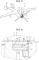
- Fig. 5 illustrates still another flying object 9 including motor unit 1 of the present exemplary embodiment.
- Flying object 9 has elements common to flying object 8 illustrated in Fig. 4 . For this reason, the description of matters of flying object 9 overlapping with flying object 8 will be omitted below.
- Flying object 9 includes body 90 and one motor unit 1.
- Body 90 has the same configuration as that of body 80 of flying object 8 illustrated in Fig. 4 .
- Motor unit 1 is attached to a nose, which is a front end of body 90.
- Motor unit 1 is attached to body 90 such that first rotary vane 11 and second rotary vane 12 are positioned in front of stator 20, and the propulsion force generated by first rotary vane 11 and second rotary vane 12 acts in front.
- the gear has been described with, as an example, the configuration in which bevel gears 41, 42, 43 are used.
- the gear is not limited to the bevel gear as long as the same effects as those described above can be obtained.
- the gear can have a similar configuration even when a spur gear is used.
- motor unit (1) of a first aspect includes the following configuration.
- Motor unit (1) includes stator (20), rotor (3), and gear unit (4).
- Rotor (3) is positioned around stator (20) and rotates by a magnetic force generated in stator (20) to generate a rotational force of first rotary vane (11).
- Gear unit (4) has bevel gears (41, 42, 43), which are a plurality of gears.
- Gear unit (4) converts the rotational force generated by rotor (3) to generate a rotational force for rotating second rotary vane (12) in an inverse direction to the rotation direction of first rotary vane (11). At least a part of the plurality of bevel gears (41, 42, 43) are positioned inside stator (20).
- stator (20) since at least a part of the plurality of bevel gears (41, 42, 43) are positioned inside stator (20), it is possible to suppress an increase in size in the direction in which axial center (30) of motor unit (1) extends.
- First rotary vane (11) and second rotary vane (12) can be disposed close to stator (20) and rotor (3) in the direction in which axial center (30) of rotor (3) extends. For this reason, by shortening the members such as shafts (61, 62) that transmit the rotational force of rotor (3) to first rotary vane (11) and second rotary vane (12), it is possible to suppress vibration of the members such as shafts (61, 62).
- Motor unit (1) of a second aspect can be achieved by a combination with the first aspect.
- most of the plurality of bevel gears (41, 42, 43) are positioned inside stator (20).
- more than half of the plurality of bevel gears (41, 42, 43) are positioned inside stator (20).
- Motor unit (1) of a third aspect can be achieved by a combination with the first or second aspect.
- Motor unit (1) of the third aspect further includes first shaft (61) and second shaft (62).
- First shaft (61) transmits the rotational force generated by rotor (3) to first rotary vane (11).
- Second shaft (62) transmits the rotational force generated by gear unit (4) to second rotary vane (12).
- First shaft (61) is formed in a tubular shape, is positioned around second shaft (62), and is rotatably supported by second shaft (62).
- first shaft (61) by using second shaft (62) that transmits, to second rotary vane (12), the rotational force output by gear unit (4). Therefore, it is possible to suppress an increase in size in a direction orthogonal to axial center (30) of motor unit (1).
- Motor unit (1) of a fourth aspect can be achieved by a combination with any one of the first to third aspects.
- the plurality of bevel gears (41, 42, 43) of the fourth aspect include first bevel gear (41) connected to rotor (3).
- Motor unit (1) of a fifth aspect can be achieved by a combination with any one of the first to third aspects.
- Gear unit (4) of the fifth aspect includes first bevel gear (41), second bevel gear (42), and third bevel gear (43) as a plurality of bevel gears.
- First bevel gear (41) rotates in the rotation direction of rotor (3) by the rotational force generated by rotor (3).
- Second bevel gear (42) meshes with first bevel gear (41).
- Third bevel gear (43) meshes with second bevel gear (42) and rotates in a direction opposite to first bevel gear (41) to generate a rotational force of second rotary vane (12).
- first bevel gear (41), second bevel gear (42), and third bevel gear (43) it is possible to convert the rotational force generated in rotor (3) into the rotational force in the opposite direction for rotating second rotary vane (12).
- Third bevel gear (43) meshes with second bevel gear (42) and rotates in a direction opposite to first bevel gear (41) to generate a rotational force of second rotary vane (12).
- First shaft (61) rotates integrally with first bevel gear (41).
- Second shaft (62) rotates integrally with third bevel gear (43).
Landscapes
- Engineering & Computer Science (AREA)
- Mechanical Engineering (AREA)
- Aviation & Aerospace Engineering (AREA)
- Power Engineering (AREA)
- Chemical & Material Sciences (AREA)
- Combustion & Propulsion (AREA)
- Connection Of Motors, Electrical Generators, Mechanical Devices, And The Like (AREA)
Applications Claiming Priority (2)
| Application Number | Priority Date | Filing Date | Title |
|---|---|---|---|
| JP2020212813 | 2020-12-22 | ||
| PCT/JP2021/040919 WO2022137840A1 (ja) | 2020-12-22 | 2021-11-08 | モータユニット及び飛行体 |
Publications (3)
| Publication Number | Publication Date |
|---|---|
| EP4269240A1 EP4269240A1 (en) | 2023-11-01 |
| EP4269240A4 EP4269240A4 (en) | 2024-05-01 |
| EP4269240B1 true EP4269240B1 (en) | 2025-02-26 |
Family
ID=82157554
Family Applications (1)
| Application Number | Title | Priority Date | Filing Date |
|---|---|---|---|
| EP21909994.2A Active EP4269240B1 (en) | 2020-12-22 | 2021-11-08 | Motor unit and flying object |
Country Status (5)
| Country | Link |
|---|---|
| US (1) | US20240030780A1 (https=) |
| EP (1) | EP4269240B1 (https=) |
| JP (1) | JPWO2022137840A1 (https=) |
| CN (1) | CN116601079A (https=) |
| WO (1) | WO2022137840A1 (https=) |
Families Citing this family (1)
| Publication number | Priority date | Publication date | Assignee | Title |
|---|---|---|---|---|
| US12122503B1 (en) * | 2021-09-20 | 2024-10-22 | Wisk Aero Llc | Aerodynamic rotor blade configurations |
Family Cites Families (21)
| Publication number | Priority date | Publication date | Assignee | Title |
|---|---|---|---|---|
| US9434471B2 (en) * | 2005-04-14 | 2016-09-06 | Paul E Arlton | Rotary wing vehicle |
| US8253294B1 (en) * | 2008-05-02 | 2012-08-28 | E-Wish Technology, Llc | Increased efficiency dual rotational electric motor/generator |
| KR20090089822A (ko) * | 2009-07-21 | 2009-08-24 | 곽상호 | 중심부에 회전날개와 자극을 결합한 회전체를 이용한 모터의 구조 |
| US20130181562A1 (en) * | 2012-01-17 | 2013-07-18 | Hamilton Sundstrand Corporation | Dual-rotor machine |
| WO2015108147A1 (ja) * | 2014-01-16 | 2015-07-23 | アイシン・エィ・ダブリュ株式会社 | 車両用駆動装置 |
| US9906106B1 (en) * | 2014-01-31 | 2018-02-27 | Maestra Energy, Llc | Electrical generator or motor with variable coil winding patterns exhibiting multiple wires incorporated into a plurality coil configurations defined around a rotor and incorporating a gearbox arrangement exhibiting oppositely driven rotor and stator gears configured with multi-tiered reversing gears exhibiting both straight and helical patterns and for varying turning ratios for establishing either of acceleration or deceleration aspects for increased power output |
| KR101601418B1 (ko) * | 2014-05-20 | 2016-03-09 | 현대중공업 주식회사 | 선박용 추진장치 |
| WO2016180750A1 (en) * | 2015-05-08 | 2016-11-17 | Rolls-Royce Ab | A marine vessel propulsion device, a pod unit and a marine vessel. |
| US10407169B2 (en) * | 2016-08-30 | 2019-09-10 | Bell Textron Inc. | Aircraft having dual rotor-to-wing conversion capabilities |
| JP6409999B2 (ja) * | 2016-09-21 | 2018-10-24 | 日本精工株式会社 | 電動車両駆動装置 |
| CN107352024A (zh) * | 2017-07-12 | 2017-11-17 | 重庆国飞通用航空设备制造有限公司 | 共轴双桨反向旋翼机构及其飞行器 |
| US10988247B2 (en) * | 2017-10-19 | 2021-04-27 | Uvionix Aerospace Corporation | Unmanned aerial vehicle and propulsion system for an unmanned aerial vehicle |
| US11509208B2 (en) * | 2017-12-18 | 2022-11-22 | Sony Corporation | Actuator with increased torque-to-weight ratio |
| JP6425845B1 (ja) * | 2018-03-01 | 2018-11-21 | 株式会社Tkkワークス | 産業用無人ヘリコプタ |
| US20190283864A1 (en) * | 2018-03-16 | 2019-09-19 | Hamilton Sundstrand Corporation | Counter-rotating propeller system with capability to stop rotation of one row |
| EP4434894A3 (en) * | 2018-04-17 | 2025-01-15 | The Maglev Aero Co. | Systems and methods for vertical takeoff and landing using magnetic levitation |
| US10663041B2 (en) * | 2018-08-14 | 2020-05-26 | Hamilton Sunstrand Corporation | Jam-tolerant electric linear actuator |
| US20200216183A1 (en) * | 2019-01-08 | 2020-07-09 | Hamilton Sundstrand Corporation | Rotary propulsion systems and methods of propelling vehicles using rotary propulsion systems |
| GB201900478D0 (en) * | 2019-01-14 | 2019-02-27 | Rolls Royce Plc | Turbomachine |
| CN111332462B (zh) * | 2020-02-24 | 2021-08-03 | 北京理工大学 | 一种便携式小型筒式共轴反桨三叶片旋翼式无人机 |
| US11702197B2 (en) * | 2020-03-19 | 2023-07-18 | Lockheed Martin Corporation | Coaxial split torque gearbox with sequential load distribution |
-
2021
- 2021-11-08 US US18/257,117 patent/US20240030780A1/en not_active Abandoned
- 2021-11-08 WO PCT/JP2021/040919 patent/WO2022137840A1/ja not_active Ceased
- 2021-11-08 JP JP2022571940A patent/JPWO2022137840A1/ja not_active Ceased
- 2021-11-08 CN CN202180084160.7A patent/CN116601079A/zh active Pending
- 2021-11-08 EP EP21909994.2A patent/EP4269240B1/en active Active
Also Published As
| Publication number | Publication date |
|---|---|
| WO2022137840A1 (ja) | 2022-06-30 |
| EP4269240A1 (en) | 2023-11-01 |
| EP4269240A4 (en) | 2024-05-01 |
| US20240030780A1 (en) | 2024-01-25 |
| CN116601079A (zh) | 2023-08-15 |
| JPWO2022137840A1 (https=) | 2022-06-30 |
Similar Documents
| Publication | Publication Date | Title |
|---|---|---|
| US10975870B2 (en) | Bracketless magnetic pump | |
| US11975829B2 (en) | Motor unit and aircraft | |
| EP3605802A1 (en) | All-weather motor | |
| CA2938534C (en) | A magnetically geared electric drive | |
| EP3483055A1 (en) | Submersible electric thruster | |
| US20210129984A1 (en) | Unmanned aerial vehicle | |
| JPH0156624B2 (https=) | ||
| KR20200100683A (ko) | 컴팩트 기어 모터 | |
| EP4269240B1 (en) | Motor unit and flying object | |
| JP2012070558A (ja) | 電気機械装置およびそれを用いたアクチュエーター、モーター | |
| US12149127B2 (en) | Rotor for electric motor | |
| EP3290731B1 (en) | Drone with magnet fluid sealed bearing unit and drive motor having the bearing unit | |
| WO2021212323A1 (zh) | 电机、动力装置及无人飞行器 | |
| JPWO2022137840A5 (https=) | ||
| EP4261126A1 (en) | Motor unit and aircraft | |
| US10633083B2 (en) | Unmanned aerial vehicle and method for driving an unmanned aerial vehicle | |
| JP2018062275A (ja) | 水中推進装置および水中探査装置 | |
| US10518910B1 (en) | Agile attitude control system for small spacecraft | |
| KR101703822B1 (ko) | 회전소나시스템을 구비한 초소형 수상 로봇 | |
| JP2018129894A (ja) | アウターロータ型モータおよび飛行装置 | |
| US20150108864A1 (en) | Coaxial direct drive system | |
| CN210167889U (zh) | 一种采用防水结构设计的无轴式内转子无刷电机 | |
| CN212784927U (zh) | 电机及手持云台 | |
| JP6398145B2 (ja) | 無人航空機およびその保管方法 | |
| CN110417168A (zh) | 一种采用防水结构设计的无轴式内转子无刷电机 |
Legal Events
| Date | Code | Title | Description |
|---|---|---|---|
| STAA | Information on the status of an ep patent application or granted ep patent |
Free format text: STATUS: THE INTERNATIONAL PUBLICATION HAS BEEN MADE |
|
| PUAI | Public reference made under article 153(3) epc to a published international application that has entered the european phase |
Free format text: ORIGINAL CODE: 0009012 |
|
| STAA | Information on the status of an ep patent application or granted ep patent |
Free format text: STATUS: REQUEST FOR EXAMINATION WAS MADE |
|
| 17P | Request for examination filed |
Effective date: 20230627 |
|
| AK | Designated contracting states |
Kind code of ref document: A1 Designated state(s): AL AT BE BG CH CY CZ DE DK EE ES FI FR GB GR HR HU IE IS IT LI LT LU LV MC MK MT NL NO PL PT RO RS SE SI SK SM TR |
|
| REG | Reference to a national code |
Ref country code: DE Ref legal event code: R079 Free format text: PREVIOUS MAIN CLASS: B64C0039020000 Ipc: B64D0035026000 Ref country code: DE Ref legal event code: R079 Ref document number: 602021026941 Country of ref document: DE Free format text: PREVIOUS MAIN CLASS: B64C0039020000 Ipc: B64D0035026000 |
|
| DAV | Request for validation of the european patent (deleted) | ||
| DAX | Request for extension of the european patent (deleted) | ||
| A4 | Supplementary search report drawn up and despatched |
Effective date: 20240402 |
|
| RIC1 | Information provided on ipc code assigned before grant |
Ipc: B64C 11/02 20060101ALI20240325BHEP Ipc: F16H 55/22 20060101ALI20240325BHEP Ipc: H02K 7/116 20060101ALI20240325BHEP Ipc: B64D 35/06 20060101ALI20240325BHEP Ipc: B64D 27/24 20060101ALI20240325BHEP Ipc: B64D 35/026 20240101AFI20240325BHEP |
|
| GRAP | Despatch of communication of intention to grant a patent |
Free format text: ORIGINAL CODE: EPIDOSNIGR1 |
|
| STAA | Information on the status of an ep patent application or granted ep patent |
Free format text: STATUS: GRANT OF PATENT IS INTENDED |
|
| RIC1 | Information provided on ipc code assigned before grant |
Ipc: B64C 11/02 20060101ALI20240829BHEP Ipc: F16H 55/22 20060101ALI20240829BHEP Ipc: H02K 7/116 20060101ALI20240829BHEP Ipc: B64D 35/06 20060101ALI20240829BHEP Ipc: B64D 27/24 20060101ALI20240829BHEP Ipc: B64D 35/026 20240101AFI20240829BHEP |
|
| INTG | Intention to grant announced |
Effective date: 20240920 |
|
| GRAS | Grant fee paid |
Free format text: ORIGINAL CODE: EPIDOSNIGR3 |
|
| P01 | Opt-out of the competence of the unified patent court (upc) registered |
Free format text: CASE NUMBER: APP_65748/2024 Effective date: 20241212 |
|
| GRAA | (expected) grant |
Free format text: ORIGINAL CODE: 0009210 |
|
| STAA | Information on the status of an ep patent application or granted ep patent |
Free format text: STATUS: THE PATENT HAS BEEN GRANTED |
|
| AK | Designated contracting states |
Kind code of ref document: B1 Designated state(s): AL AT BE BG CH CY CZ DE DK EE ES FI FR GB GR HR HU IE IS IT LI LT LU LV MC MK MT NL NO PL PT RO RS SE SI SK SM TR |
|
| REG | Reference to a national code |
Ref country code: GB Ref legal event code: FG4D |
|
| REG | Reference to a national code |
Ref country code: CH Ref legal event code: EP |
|
| REG | Reference to a national code |
Ref country code: DE Ref legal event code: R096 Ref document number: 602021026941 Country of ref document: DE |
|
| REG | Reference to a national code |
Ref country code: IE Ref legal event code: FG4D |
|
| REG | Reference to a national code |
Ref country code: NL Ref legal event code: MP Effective date: 20250226 |
|
| PG25 | Lapsed in a contracting state [announced via postgrant information from national office to epo] |
Ref country code: RS Free format text: LAPSE BECAUSE OF FAILURE TO SUBMIT A TRANSLATION OF THE DESCRIPTION OR TO PAY THE FEE WITHIN THE PRESCRIBED TIME-LIMIT Effective date: 20250526 |
|
| PG25 | Lapsed in a contracting state [announced via postgrant information from national office to epo] |
Ref country code: FI Free format text: LAPSE BECAUSE OF FAILURE TO SUBMIT A TRANSLATION OF THE DESCRIPTION OR TO PAY THE FEE WITHIN THE PRESCRIBED TIME-LIMIT Effective date: 20250226 |
|
| PG25 | Lapsed in a contracting state [announced via postgrant information from national office to epo] |
Ref country code: PL Free format text: LAPSE BECAUSE OF FAILURE TO SUBMIT A TRANSLATION OF THE DESCRIPTION OR TO PAY THE FEE WITHIN THE PRESCRIBED TIME-LIMIT Effective date: 20250226 |
|
| PG25 | Lapsed in a contracting state [announced via postgrant information from national office to epo] |
Ref country code: ES Free format text: LAPSE BECAUSE OF FAILURE TO SUBMIT A TRANSLATION OF THE DESCRIPTION OR TO PAY THE FEE WITHIN THE PRESCRIBED TIME-LIMIT Effective date: 20250226 |
|
| REG | Reference to a national code |
Ref country code: LT Ref legal event code: MG9D |
|
| PG25 | Lapsed in a contracting state [announced via postgrant information from national office to epo] |
Ref country code: NO Free format text: LAPSE BECAUSE OF FAILURE TO SUBMIT A TRANSLATION OF THE DESCRIPTION OR TO PAY THE FEE WITHIN THE PRESCRIBED TIME-LIMIT Effective date: 20250526 Ref country code: IS Free format text: LAPSE BECAUSE OF FAILURE TO SUBMIT A TRANSLATION OF THE DESCRIPTION OR TO PAY THE FEE WITHIN THE PRESCRIBED TIME-LIMIT Effective date: 20250626 |
|
| PG25 | Lapsed in a contracting state [announced via postgrant information from national office to epo] |
Ref country code: NL Free format text: LAPSE BECAUSE OF FAILURE TO SUBMIT A TRANSLATION OF THE DESCRIPTION OR TO PAY THE FEE WITHIN THE PRESCRIBED TIME-LIMIT Effective date: 20250226 |
|
| PG25 | Lapsed in a contracting state [announced via postgrant information from national office to epo] |
Ref country code: HR Free format text: LAPSE BECAUSE OF FAILURE TO SUBMIT A TRANSLATION OF THE DESCRIPTION OR TO PAY THE FEE WITHIN THE PRESCRIBED TIME-LIMIT Effective date: 20250226 |
|
| PG25 | Lapsed in a contracting state [announced via postgrant information from national office to epo] |
Ref country code: PT Free format text: LAPSE BECAUSE OF FAILURE TO SUBMIT A TRANSLATION OF THE DESCRIPTION OR TO PAY THE FEE WITHIN THE PRESCRIBED TIME-LIMIT Effective date: 20250626 Ref country code: LV Free format text: LAPSE BECAUSE OF FAILURE TO SUBMIT A TRANSLATION OF THE DESCRIPTION OR TO PAY THE FEE WITHIN THE PRESCRIBED TIME-LIMIT Effective date: 20250226 |
|
| PG25 | Lapsed in a contracting state [announced via postgrant information from national office to epo] |
Ref country code: GR Free format text: LAPSE BECAUSE OF FAILURE TO SUBMIT A TRANSLATION OF THE DESCRIPTION OR TO PAY THE FEE WITHIN THE PRESCRIBED TIME-LIMIT Effective date: 20250527 Ref country code: BG Free format text: LAPSE BECAUSE OF FAILURE TO SUBMIT A TRANSLATION OF THE DESCRIPTION OR TO PAY THE FEE WITHIN THE PRESCRIBED TIME-LIMIT Effective date: 20250226 |
|
| REG | Reference to a national code |
Ref country code: AT Ref legal event code: MK05 Ref document number: 1770439 Country of ref document: AT Kind code of ref document: T Effective date: 20250226 |
|
| PG25 | Lapsed in a contracting state [announced via postgrant information from national office to epo] |
Ref country code: SE Free format text: LAPSE BECAUSE OF FAILURE TO SUBMIT A TRANSLATION OF THE DESCRIPTION OR TO PAY THE FEE WITHIN THE PRESCRIBED TIME-LIMIT Effective date: 20250226 |
|
| PG25 | Lapsed in a contracting state [announced via postgrant information from national office to epo] |
Ref country code: SM Free format text: LAPSE BECAUSE OF FAILURE TO SUBMIT A TRANSLATION OF THE DESCRIPTION OR TO PAY THE FEE WITHIN THE PRESCRIBED TIME-LIMIT Effective date: 20250226 |
|
| PG25 | Lapsed in a contracting state [announced via postgrant information from national office to epo] |
Ref country code: DK Free format text: LAPSE BECAUSE OF FAILURE TO SUBMIT A TRANSLATION OF THE DESCRIPTION OR TO PAY THE FEE WITHIN THE PRESCRIBED TIME-LIMIT Effective date: 20250226 |
|
| PG25 | Lapsed in a contracting state [announced via postgrant information from national office to epo] |
Ref country code: IT Free format text: LAPSE BECAUSE OF FAILURE TO SUBMIT A TRANSLATION OF THE DESCRIPTION OR TO PAY THE FEE WITHIN THE PRESCRIBED TIME-LIMIT Effective date: 20250226 |
|
| PG25 | Lapsed in a contracting state [announced via postgrant information from national office to epo] |
Ref country code: AT Free format text: LAPSE BECAUSE OF FAILURE TO SUBMIT A TRANSLATION OF THE DESCRIPTION OR TO PAY THE FEE WITHIN THE PRESCRIBED TIME-LIMIT Effective date: 20250226 |
|
| PG25 | Lapsed in a contracting state [announced via postgrant information from national office to epo] |
Ref country code: CZ Free format text: LAPSE BECAUSE OF FAILURE TO SUBMIT A TRANSLATION OF THE DESCRIPTION OR TO PAY THE FEE WITHIN THE PRESCRIBED TIME-LIMIT Effective date: 20250226 Ref country code: EE Free format text: LAPSE BECAUSE OF FAILURE TO SUBMIT A TRANSLATION OF THE DESCRIPTION OR TO PAY THE FEE WITHIN THE PRESCRIBED TIME-LIMIT Effective date: 20250226 |
|
| PG25 | Lapsed in a contracting state [announced via postgrant information from national office to epo] |
Ref country code: RO Free format text: LAPSE BECAUSE OF FAILURE TO SUBMIT A TRANSLATION OF THE DESCRIPTION OR TO PAY THE FEE WITHIN THE PRESCRIBED TIME-LIMIT Effective date: 20250226 |
|
| PG25 | Lapsed in a contracting state [announced via postgrant information from national office to epo] |
Ref country code: SK Free format text: LAPSE BECAUSE OF FAILURE TO SUBMIT A TRANSLATION OF THE DESCRIPTION OR TO PAY THE FEE WITHIN THE PRESCRIBED TIME-LIMIT Effective date: 20250226 |
|
| REG | Reference to a national code |
Ref country code: DE Ref legal event code: R097 Ref document number: 602021026941 Country of ref document: DE |
|
| PLBE | No opposition filed within time limit |
Free format text: ORIGINAL CODE: 0009261 |
|
| STAA | Information on the status of an ep patent application or granted ep patent |
Free format text: STATUS: NO OPPOSITION FILED WITHIN TIME LIMIT |
|
| 26N | No opposition filed |
Effective date: 20251127 |