EP4268664B1 - Verbesserter ohrring oder broschenrücken - Google Patents
Verbesserter ohrring oder broschenrücken Download PDFInfo
- Publication number
- EP4268664B1 EP4268664B1 EP23198168.9A EP23198168A EP4268664B1 EP 4268664 B1 EP4268664 B1 EP 4268664B1 EP 23198168 A EP23198168 A EP 23198168A EP 4268664 B1 EP4268664 B1 EP 4268664B1
- Authority
- EP
- European Patent Office
- Prior art keywords
- pressing element
- spring
- stop
- passage
- bottom shell
- Prior art date
- Legal status (The legal status is an assumption and is not a legal conclusion. Google has not performed a legal analysis and makes no representation as to the accuracy of the status listed.)
- Active
Links
Images


Classifications
-
- A—HUMAN NECESSITIES
- A44—HABERDASHERY; JEWELLERY
- A44C—PERSONAL ADORNMENTS, e.g. JEWELLERY; COINS
- A44C7/00—Ear-rings; Devices for piercing the ear-lobes
- A44C7/003—Ear-studs or their catch devices
-
- A—HUMAN NECESSITIES
- A44—HABERDASHERY; JEWELLERY
- A44C—PERSONAL ADORNMENTS, e.g. JEWELLERY; COINS
- A44C1/00—Brooches or clips in their decorative or ornamental aspect
Definitions
- the field of the invention relates to earring and brooch backs for receiving a post which is provided with at least one groove, wherein the post can be locked in the back. More specifically, the invention relates to earring and brooch backs comprising a housing with a bottom shell and a top shell, a first and a second pressing element between the bottom shell and the top shell, and at least one spring.
- FR 454459 thus describes an earring back with a housing with a bottom shell and a top shell between which two pressing elements are provided. These pressing elements are spring-mounted using two springs.
- a drawback of the described back is that it comprises many individual parts and that assembly of the back is time-consuming.
- KR 10-2012-0027609 describes an earring back with a top shell, a bottom shell and two pressing elements which are each provided with a spring element and with a hole for allowing passage of a post.
- the object of embodiments of the present invention is to provide an earring or brooch back of the type stated in the preamble with a limited number of parts and an improved positioning of the parts in the housing, which allows in particular an improved assembly of the back.
- an earring or brooch back having the features of claim 1 for receiving a post which is provided with at least one groove.
- the back comprises a housing with a bottom shell and a top shell, a first and second pressing element between the bottom shell and the top shell, and at least one spring for spring-mounting the first and second pressing element in the housing.
- the bottom shell and the top shell are provided with mutually aligned openings for forming a passage for the post.
- the first pressing element is provided with a first stop for the post and a first protruding part which protrudes from the housing, wherein the passage lies between the first stop and the first protruding part.
- the second pressing element is provided with a second stop for the post and with a second protruding part which protrudes from the housing, wherein the passage lies between the second stop and the second protruding part.
- the first and second stop lie on either side of a post to be inserted.
- the bottom shell is preferably formed on the inner side thereof with a first internal guide part for guiding the first pressing element and with a second internal guide part for guiding the second pressing element, wherein the first and second guide part lie on either side of the passage for the post.
- the first and second pressing element are preferably provided with, and particularly formed with, respectively at least a first and a second guide wall against which the at least one spring acts for the purpose of pressing respectively the first and second protruding part of the first and second pressing element outward.
- the first guide wall lies substantially between the passage and the first protruding part
- the second guide wall lies substantially between the passage and the second protruding part, such that the distance between the first stop and the second stop can be increased by pressing the first and second protruding part inward.
- the at least one spring can be arranged on the first and second pressing element in simple manner during assembly of the back, after the first and second pressing element have been placed in the bottom shell.
- the first and second guide wall here provide for a good positioning of the spring.
- the first and second pressing element is provided with, preferably formed with, respectively at least a first and second guide groove for the at least one spring.
- the first guide wall is then formed by a wall of the first guide groove
- the second guide wall is then formed by a wall of the second guide groove.
- the first stop lies opposite the second stop as seen in a pressing direction of the first and second pressing element, which pressing direction is perpendicular to an axis of the passage in which the post can be received.
- the first and second stop are preferably arranged symmetrically relative to the axis of the passage.
- the first and second stop preferably have the same thickness as measured in the direction of the axis of the passage. This thickness is preferably smaller than 0.6 mm, more preferably smaller than 0.5 mm. In the fully pressed-in position the distance between the first and second stop can for instance lie between 1.0 mm and 2.0 mm. In the non-pressed-in position the distance can for instance lie between 0.2 mm and 0.6 mm.
- the first and second pressing element are embodied such that when the first and second protruding element are pressed inward, the first pressing element comes to a stop against the second stop and the second pressing element comes to a stop against the first stop. In this way the first pressing element thus forms a stop for the second pressing element, and vice versa.
- the bottom shell is provided on an inner side thereof with, and particularly formed with, at least one protruding positioning part for positioning the at least one spring.
- the positioning part and the above stated first or second guide part can be the same part, this on the one hand having a positioning function for the at least one spring and on the other hand a guiding function for guiding the pressing elements.
- a positioning and guide part can thus be provided which has a first wall against which the spring is positioned, and a second wall against which a pressing element is positioned. It is however also possible to provide separate parts for positioning the spring and for guiding the pressing elements.
- the bottom shell on the inner side thereof with a protruding positioning part, preferably formed integrally with the bottom shell, for positioning the at least one spring the positioning of the at least one spring can be improved further without additional parts being necessary in the back.
- the first guide part for guiding the first pressing element has a first guide wall which is parallel to a second guide wall of the second guide part for guiding the second pressing element.
- the direction of these first and second guide walls is parallel to the pressing direction in which the first and second pressing element are movable. In this way the first and second pressing element can be guided in improved manner, wherein a wall of the first pressing element makes contact with the first guide wall and a wall of the second pressing element makes contact with the second guide wall.
- the first and second pressing element including the possible guide walls, are preferably each formed integrally.
- the spring preferably has a first spring-mounted leg against the first guide wall of the first pressing element and a second spring-mounted leg against the second guide wall of the second pressing element.
- the spring preferably has substantially a V-shape or a U-shape.
- the first and second leg extend substantially along a circular periphery around the passage P. It is however also possible to give the spring a round U-shape, and the shape thus need not be a perfect circle segment.
- the spring comprises a spiral-shaped or wave-shaped part which is arranged around or against the positioning part.
- the first and second leg preferably extend on either side of the spiral-shaped or wave-shaped part. It is however also possible to provide two springs, each provided with a spiral-shaped part, wherein a first spring fulfils the function of the first leg and a second spring fulfils the function of the second leg.
- the first and second spring-mounted leg and the spiral-shaped or wave-shaped part is formed integrally.
- the first and second guide wall with which the first and second pressing element are equipped are configured to support respectively the first and second leg at one contact point each in the different positions of the first and second pressing elements. This contact point can remain the same in the different positions.
- the first and second guide wall with which the first and second pressing element are equipped are configured to support respectively the first and second leg at two contact points each in the different positions of the first and second pressing elements. In this way the friction between the first and second guide wall and the first and second leg can be limited in some embodiments, which results in a smoother opening and closing of the back.
- the first pressing element extends substantially U-shaped around the passage with a first leg which forms the first stop.
- the second pressing element can also extend substantially U-shaped around the passage with a second leg which forms the second stop.
- the first leg lies partially in the U-shaped part of the second pressing element and the second leg lies partially in the U-shaped part of the first pressing element, such that the first and second pressing element hook into each other, as it were.
- the at least one positioning part for the at least one spring comprises a pin. It is particularly when the spring is provided with a spiral-shaped or wave-shaped part that this spiral-shaped or wave-shaped part can be arranged around the pin. It is however also possible to provide the positioning part with a deepened portion or recess in which a part of the spring, for instance the spiral-shaped or wave-shaped part, can be received.
- the spring is a wire spring.
- the spring is preferably manufactured from metal, for instance titanium.
- the diameter of the spring is preferably smaller than 1 mm, more preferably smaller than 0.5 mm.
- the length of the spring preferably lies between 7 and 10 mm, more preferably between 6 and 11 mm.
- the diameter of the bottom shell preferably lies between 5 mm and 9 mm, more preferably between 6 mm and 8 mm.
- the bottom shell is provided with a first and a second stepped peripheral part on which the top shell is mounted.
- the first and second pressing element extend between the first and second stepped peripheral part. It is however also possible to provide peripheral parts which are not stepped. Giving the peripheral parts a stepped form however enables the top shell to be positioned and mounted in simpler manner.
- a method for manufacturing an earring or brooch back comprising the following steps of:
- the top shell and/or the bottom shell are preferably manufactured from metal by turning and/or milling.
- the first and the second pressing element are preferably manufactured by lasering.
- the first and second pressing element will preferably be arranged during the above described method such that they make contact with the first and second guide part.
- the at least one spring When the bottom shell is formed on an inner side thereof with at least one protruding positioning part for positioning the at least one spring, the at least one spring will preferably be arranged on the first and second pressing element such that the at least one spring supports against the positioning part.
- the at least one spring is preferably arranged such that it acts for the purpose of pressing respectively the first and second protruding part outward, wherein the first guide wall lies substantially between the passage and the first protruding part and the second guide wall lies substantially between the passage and the second protruding part, such that the distance between the first and the second stop can be increased by the action of the spring against the first and second guide wall.
- an earring or brooch back for the purpose of receiving a post which is provided with at least one groove, comprising: a housing comprising a bottom shell and a top shell, wherein the bottom shell and the top shell are provided with mutually aligned openings for forming a passage for the post; a first and a second pressing element between the bottom shell and the top shell, wherein the first pressing element is provided with a first stop for the post and a first protruding part which protrudes from the housing, wherein the passage lies between the first stop and the first protruding part, and wherein the second pressing element is provided with a second stop for the post and with a second protruding part which protrudes from the housing, wherein the passage lies between the second stop and the second protruding part, wherein the first and second stop lie on either side of a post to be inserted; at least one spring for spring-mounting the first and second pressing element; wherein the bottom shell is provided on an inner side thereof with
- the spring is arranged tensioned between the two pressing elements, wherein the spring is also tensioned in the uncompressed state. By giving the pressing elements a suitable form, the spring can then remain in place without additional positioning parts being necessary on the inner side of the bottom shell.
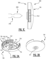
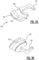
- FIGS 1A, 1B , 1C, 2A , 2B , 3A , 3B , 4A, 4B illustrate a first embodiment of an earring back 100 according to the invention.
- Earring back 100 is intended for the purpose of receiving a post 200 with at least one groove 210.
- Earring back 100 comprises a housing with a bottom shell 110 and a top shell 120, a first and a second pressing element 130, 140 between the bottom shell and the top shell, and a spring 150 for spring-mounting the first and second pressing element.
- Bottom shell 110 and top shell 120 are provided with mutually aligned openings 111, 121 for forming a passage P for post 200.
- First pressing element 130 is provided with a first stop 131 for post 200 and a first protruding part 132 which protrudes from the housing, wherein the passage P lies between first stop 131 and first protruding part 132.
- the second pressing element 140 is provided with a second stop 141 for post 200 and with a second protruding part 142 which protrudes from the housing, wherein the passage P lies between second stop 141 and second protruding part 142.
- the first and second stop lie on either side of a post 200 to be inserted, and are intended to engage in groove 210.
- Bottom shell 110 is formed on the inner side with a first internal guide part 113 for guiding first pressing element 130 and with a second internal guide part 114 for guiding the second pressing element 140, wherein the first and second internal guide part 113, 114 lie on either side of the passage for the post.
- Bottom shell 110 is further provided on an inner side thereof with, and preferably formed with, a protruding positioning part 115 for positioning the at least one spring 150.
- guide part 113 and positioning part 115 are mutually adjoining, wherein guide walls 113' fulfil a guiding function of the pressing elements and positioning walls 115' fulfil the positioning function.
- the first internal guide part 113 has a first guide wall 113' which is parallel to a second guide wall 114' of the second internal guide part 114, and is parallel to the pressing/pushing direction in which the first and second pressing elements can be pressed/pushed inward.
- the first and the second pressing element 130, 140 are provided with, and preferably formed with, respectively at least a first and a second guide wall 135, 145 against which the at least one spring acts for the purpose of pressing respectively the first and second protruding part outward.
- First guide wall 135 lies substantially between the passage P and first protruding part 132 and second guide wall 145 lies substantially between the passage P and second protruding part 142, such that the distance d between first stop 131 and second stop 141 can be increased by pressing the first and second protruding part 132, 142 inward.
- the first and the second pressing element 130, 140 are provided with, and preferably formed with, respectively at least a first and a second guide groove 136, 146 for the spring 150.
- the first guide wall 135 is a wall of the first guide groove 136 and the second guide wall 145 is a wall of the second guide groove 146.
- the first and second pressing element 130, 140 are each formed integrally.
- Bottom shell 110, including the first and second internal guide part 113, 114 and the positioning part 115, are also formed integrally.
- Spring 150 comprises a first spring-mounted leg 153 against first guide wall 135 and a second spring-mounted leg 154 against second guide wall 145.
- First and second leg 153, 154 extend substantially along a circular periphery or round U-shape around the passage P.
- Spring 150 comprises a wave-shaped part 152 which is arranged against positioning part 115.
- First and second spring-mounted leg 153, 154 and wave-shaped part 152 are formed integrally.
- First and second guide wall 135, 145 are configured to support first and second leg 153, 154 at two contact points P1, P2 each in the different positions of the first and second pressing elements 130, 140.
- Protruding positioning part 115 comprises a recess with positioning walls 115' in which a part of spring 150 is received.
- Spring 150 is a wire spring.
- First pressing element 130 extends substantially U-shaped around the passage with a first leg which forms the first stop 131.
- Second pressing element 140 extends substantially U-shaped around the passage with a second leg which forms the second stop 141.
- First leg 131 lies partially in the U-shaped part of second pressing element 140 and second leg 141 lies partially in the U-shaped part of first pressing element 130.
- First stop 131 lies opposite second stop 141 as seen in a pressing direction of the first and second pressing element 130, 140, which pressing direction is perpendicular to an axis of the passage P in which the post can be received.
- First and second pressing element 130, 140 are pressed in, the distance between the first and second stop 131, 141 will increase so that a post 200 can be inserted.
- first and second pressing element 130, 140 are released, first and second stop 131, 141 move toward each other for fixedly clamping post 200 therebetween.
- First and second stop 131, 141 are preferably arranged symmetrically relative to the axis of the passage P.
- First and second stop 131, 141 preferably have the same thickness as measured in the direction of the axis A of the passage.
- First and second pressing element 130, 140 are embodied such that when the first and second protruding element are pressed inward, first pressing element 130 comes to a stop against second stop 141 and second pressing element 140 comes to a stop against first stop 131.
- Bottom shell 110 is provided with a first and a second stepped peripheral part 116, 117 on which top shell 120 is mounted.
- First and second pressing element 130, 140 extend between the first and second stepped peripheral part 116, 117.
- Earring back 100 according to the first embodiment can be assembled by means of the following steps:
- the top shell and the bottom shell can be manufactured from metal by turning and/or milling.
- the first and the second pressing element can be manufactured by lasering.
- the spring 150 is arranged against the at least one protruding positioning part 115, and spring 150 is arranged on the first and second pressing element such that the spring acts against the first and the second guide wall and presses them outward.
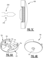
- Figures 5A, 5B , 5C, 6A , 6B , 7A , 7B , 8A, 8B illustrate a second embodiment of a back according to the invention.
- the back according to the second embodiment is similar to the back according to the first embodiment, with the difference that the positioning element for positioning the spring is formed by a pin, wherein a spiral-shaped part 151 is arranged around the pin.
- the other parts of the back are identical or similar and will not be described again.
- Figure 9 illustrates a third embodiment of a back.
- similar parts are designated with the same reference numerals, and only the differences will be discussed below.
- two springs 150a, 150b are provided instead of one spring.
- the two springs are provided with a spiral-shaped part 151a, 151b.
- the first and second pressing element are guided only by the peripheral parts 116, 117, and no internal guide parts are provided.
- the two springs of the embodiment of figure 9 can fulfil the same function as the singular spring of the first and second embodiment.
- Figure 10 shows a fourth embodiment of a back.
- one single spring 150 is used, which has the shape of a round U.
- Two positioning elements 115a, 115b are provided for the purpose of positioning the spring 150. These positioning elements 115a, 115b are formed integrally with bottom shell 110.
- the first and second pressing element are here also guided only by peripheral parts 116, 117.
- at least two additional internal guide elements are preferably provided for the purpose of guiding the movement of the first and second pressing element 130, 140.
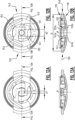
- FIGS 11 , 12A and 12B, 13A and 13B illustrate schematically a fifth embodiment of a back, which is similar to the embodiment of figures 1A-1C . Similar components are designated with the same reference numerals and will not be further elucidated here.
- first stop 131 lies opposite second stop 141 as seen in a pressing direction R of the first and second pressing element 130, 140, which pressing direction R is perpendicular to an axis A of the passage P in which the post can be received.
- first and second pressing element 130, 140 are pressed in, the distance between the first and second stop 131, 141 will increase so that a post 200 can be inserted.
- first and second pressing element 130, 140 are released, first and second stop 131, 141 move toward each other for fixedly clamping the post therebetween.
- First and second stop 131, 141 are preferably arranged symmetrically relative to the axis of the passage P.
- First and second stop 131, 141 preferably lie in the same plane.
- the lower surface 131b, 141b of the first and second stop 131, 141 preferably also lie in the same plane.
- First and second stop 131, 141 preferably have the same thickness d as measured in the direction of the axis A of the passage P, see figures 13A and 13B .
- This thickness d is preferably smaller than 0.6 mm, more preferably smaller than 0.5 mm.
- the distance a2 between the first and second stop 131, 141 can for instance lie between 1.0 mm and 2.0 mm, see figure 12B .
- the distance a1 can for instance lie between 0.2 mm and 0.6 mm, see figure 12A .
- first and second pressing element 130, 140 are embodied such that when the first and second protruding element are pressed inward, first pressing element 130 comes to a stop against second stop 141 and second pressing element 140 comes to a stop against first stop 131, see figure 12B .
- first stop 131 has an inner side which is directed toward the passage and is intended to come into contact with a post 200, and an outer side which is directed toward the protruding part 142 of second pressing element 140, wherein the outer side of first stop 131 is intended to form a stop for second pressing element 140.
- second stop 141 wherein second stop 141 has an outer side which is directed toward the protruding part 132 of first pressing element 130, wherein the outer side of second stop 141 is intended to form a stop for the first pressing element 130.
- Spring 150 comprises a first spring-mounted leg 153 against first guide wall 135 and a second spring-mounted leg 154 against second guide wall 145.
- First and second leg 153, 154 extend substantially V-shaped around the passage P.
- Spring 150 is preferably manufactured from metal, for instance titanium.
- the diameter of spring 150 is preferably smaller than 1 millimetre, more preferably smaller than 0.5 mm.
- the length of the spring preferably lies between 7 and 10 mm, more preferably between 6 and 11 mm.
- the diameter D of the bottom shell preferably lies between 5 mm and 9 mm, more preferably between 6 mm and 8 mm.
Landscapes
- Adornments (AREA)
Claims (15)
- Ohrring- oder Broschen-Rückteil (100) zur Aufnahme eines mit zumindest einer Nut (210) versehenen Stiftes (200), aufweisend:ein Gehäuse mit einer unteren Schale (110) und einer oberen Schale (120), wobei die untere Schale und die obere Schale, zur Bildung eines Durchgangs (P) für den Stift, mit zueinander ausgerichteten Öffnungen (111, 121) versehen sind;ein erstes und ein zweites Drückelement (130, 140) zwischen der unteren Schale und der oberen Schale, wobei das erste Drückelement (130) mit einem ersten Anschlag (131) für den Stift und einem aus dem Gehäuse herausragenden ersten vorstehenden Teil (132) versehen ist, wobei sich der Durchgang zwischen dem ersten Anschlag und dem ersten vorstehenden Teil befindet, und wobei das zweite Drückelement (140) mit einem zweiten Anschlag (141) für den Stift und mit einem aus dem Gehäuse herausragenden zweiten vorstehenden Teil (142) versehen ist, wobei sich der Durchgang zwischen dem zweiten Anschlag und dem zweiten vorstehenden Teil befindet, wobei der erste und der zweite Anschlag auf beiden Seiten eines einzuführenden Stiftes zu liegen kommen;zumindest eine Feder (150; 150a, 150b) zur federnden Lagerung des ersten und zweiten Drückelements;wobei die untere Schale (110), zum Führen des ersten Drückelements (130) an der Innenseite, mit einem ersten inneren Führungselement (113), und zum Führen des zweiten Drückelements (140) mit einem zweiten inneren Führungselement (114) ausgebildet ist, wobei das erste und das zweite innere Führungselement (113, 114) auf beiden Seiten des Durchgangs für den Stift angeordnet sind,wobei das erste und das zweite Drückelement (130, 140) mit zumindest einer ersten bzw. einer zweiten Führungswand (135, 145) versehen sind, gegen die die zumindest eine Feder wirkt, um den ersten bzw. zweiten vorstehenden Teil nach außen zu drücken, wobei die erste Führungswand (135) im Wesentlichen zwischen dem Durchgang und dem ersten vorstehenden Teil zu liegen kommt und die zweite Führungswand (145) im Wesentlichen zwischen dem Durchgang und dem zweiten vorstehenden Teil zu liegen kommt, so dass durch Drücken des ersten und zweiten vorstehenden Teils nach innen der Abstand (d) zwischen dem ersten Anschlag und dem zweiten Anschlag vergrößert werden kann;wobei das erste und das zweite Drückelement (130, 140) zur Aufnahme der zumindest einen Feder jeweils mit zumindest einer ersten und einer zweiten Führungsnut (136, 146) versehen ist, wobei die erste Führungswand (135) eine Wand der ersten Führungsnut (136) und die zweite Führungswand (145) eine Wand der zweiten Führungsnut (146) darstellt.
- Rückteil (100) nach dem vorherigen Anspruch, wobei die untere Schale (110) zur Positionierung der zumindest einen Feder (150) an der Innenseite mit zumindest einem vorstehenden Positionierungselement (115; 115a, 115b) versehen und vorzugsweise mit diesem ausgebildet ist.
- Rückteil (100) nach einem der vorherigen Ansprüche, wobei das erste innere Führungselement (113) eine erste Führungswand aufweist, welche parallel zu einer zweiten Führungswand des zweiten inneren Führungselements (114) verläuft.
- Rückteil (100) nach einem der vorherigen Ansprüche, wobei das erste und das zweite Drückelement (130, 140) jeweils einstückig ausgebildet sind.
- Rückteil (100) nach einem der vorherigen Ansprüche, wobei die untere Schale (110), einschließlich des ersten und zweiten inneren Führungselements und des optionalen zumindest einen Positionierungselements, einstückig ausgebildet ist.
- Rückteil (100) nach einem der vorherigen Ansprüche, wobei die zumindest eine Feder aus einer einzigen Feder (150) besteht.
- Rückteil (100) nach einem der vorherigen Ansprüche, wobei die zumindest eine Feder einen ersten, gegen die erste Führungswand (135) federnd gelagerten Schenkel (153) und einen zweiten, gegen die zweite Führungswand (145) federnd gelagerten Schenkel (154) aufweist.
- Rückteil (100) nach dem vorherigen Anspruch, optional nach Anspruch 7, wobei sich der erste und der zweite Schenkel (153, 154) im Wesentlichen entlang einer V-Form, einer kreisförmigen Peripherie oder einer runden U-Form um den Durchgang (P) erstrecken.
- Rückteil (100) nach einem der vorherigen Ansprüche, wobei sich das erste Drückelement mit einem den ersten Anschlag bildenden ersten Schenkel im Wesentlichen U-förmig um den Durchgang erstreckt, und wobei sich das zweite Drückelement mit einem den zweiten Anschlag bildenden zweiten Schenkel im Wesentlichen U-förmig um den Durchgang erstreckt, wobei der erste Schenkel (131) teilweise in dem U-förmigen Teil des zweiten Drückelementes (140) angeordnet ist und der zweite Schenkel (141) teilweise in dem U-förmigen Teil des ersten Drückelementes (130) angeordnet ist.
- Rückteil (100) nach einem der vorherigen Ansprüche, wobei die Feder eine Drahtfeder darstellt.
- Rückteil (100) nach einem der vorherigen Ansprüche, wobei die untere Schale mit einem ersten und einem zweiten abgestuften Umfangsteil (116, 117) versehen ist, auf dem die obere Schale montiert ist, wobei sich das erste und das zweite Drückelement zwischen dem ersten und dem zweiten abgestuften Umfangsteil erstrecken.
- Verfahren zur Herstellung eines Rückteils (100) zur Aufnahme eines mit zumindest einer Nut (210) versehenen Stiftes (200), aufweisend:Vorsehen einer unteren Schale (110) und einer oberen Schale (120), wobei, zum Bilden eines Durchgangs (P) für den Stift, die untere Schale und die obere Schale mit zueinander ausgerichteten Öffnungen (111, 121) versehen sind; wobei die untere Schale (110) auf der Innenseite zum Führen eines ersten Drückelements (130) mit einem ersten inneren Führungselement (113), und zum Führen eines zweiten Drückelements (140) mit einem zweiten inneren Führungselement (114) ausgebildet ist, wobei das erste und das zweite innere Führungselement (113, 114) auf beiden Seiten des Durchgangs für den Stift angeordnet sind;Anordnen eines ersten und eines zweiten Drückelements (130, 140) in der untere Schale zwischen dem ersten und dem zweiten inneren Führungselement, wobei das erste Drückelement (130) mit einem ersten Anschlag (131) für den Stift und einem ersten von der unteren Schale vorstehenden Teil (132) versehen ist, wobei sich der Durchgang zwischen dem ersten Anschlag und dem ersten vorstehenden Teil befindet, und wobei das zweite Drückelement (140) mit einem zweiten Anschlag (141) für den Stift und mit einem zweiten von der unteren Schale vorstehenden Teil (142) versehen ist, wobei sich der Durchgang zwischen dem zweiten Anschlag und dem zweiten vorstehenden Teil befindet, wobei der erste und der zweite Anschlag auf beiden Seiten eines einzuführenden Stiftes zu liegen kommt;Anordnen zumindest einer komprimierten Feder (150) zwischen dem ersten und zweiten Drückelement, so dass die zumindest eine Feder gegen das erste und zweite Drückelement wirkt und diese nach außen drückt;Anordnen der oberen Schale über der zumindest einen Feder und Verbinden der oberen Schale mit der unteren Schale; wobei das erste und das zweite Drückelement (130, 140), für die zumindest eine Feder, jeweils mit zumindest einer ersten und einer zweiten Führungswand (135, 145) versehen sind, wobei die erste Führungswand (135) im Wesentlichen zwischen dem Durchgang und dem ersten vorstehenden Teil zu liegen kommt, und die zweite Führungswand (145) im Wesentlichen zwischen dem Durchgang und dem zweiten vorstehenden Teil zu liegen kommt; und wobei die zumindest eine Feder (150) zwischen dem ersten und zweiten Drückelement so angeordnet ist, dass sie gegen die erste und die zweite Führungswand wirkt und diese nach außen drückt;wobei das erste und das zweite Drückelement (130, 140) zur Aufnahme der zumindest einen Feder jeweils mit zumindest einer ersten und einer zweiten Führungsnut (136, 146) versehen ist, wobei die erste Führungswand (135) eine Wand der ersten Führungsnut (136) und die zweite Führungswand (145) eine Wand der zweiten Führungsnut (146) darstellt.
- Verfahren nach dem vorherigen Anspruch, wobei die obere Schale und die untere Schale durch Drehen und/oder Fräsen aus Metall hergestellt werden; und/oder
wobei das erste und das zweite Drückelement durch Lasern hergestellt werden. - Verfahren nach Anspruch 12 oder 13, wobei die zumindest eine Feder eine Einzelfeder darstellt, die als Drahtfeder ausgebildet ist.
- Rückteil nach einem der Ansprüche 1 bis 11, wobei der erste Anschlag dem zweiten Anschlag gegenüberliegt, gesehen in einer Pressrichtung des ersten und zweiten Presselements, welche Pressrichtung senkrecht zu einer Achse des Durchgangs ist, in dem der Stifte aufgenommen werden kann.
Applications Claiming Priority (3)
| Application Number | Priority Date | Filing Date | Title |
|---|---|---|---|
| BE20195047A BE1026997B1 (nl) | 2019-01-28 | 2019-01-28 | Verbeterde oorbel- of brochesluiting |
| PCT/IB2019/059613 WO2020157551A1 (en) | 2019-01-28 | 2019-11-08 | Improved earring or brooch back |
| EP19813942.0A EP3917354B1 (de) | 2019-01-28 | 2019-11-08 | Verbesserte rückseite für ohrring oder brosche |
Related Parent Applications (1)
| Application Number | Title | Priority Date | Filing Date |
|---|---|---|---|
| EP19813942.0A Division EP3917354B1 (de) | 2019-01-28 | 2019-11-08 | Verbesserte rückseite für ohrring oder brosche |
Publications (4)
| Publication Number | Publication Date |
|---|---|
| EP4268664A2 EP4268664A2 (de) | 2023-11-01 |
| EP4268664A3 EP4268664A3 (de) | 2023-12-13 |
| EP4268664B1 true EP4268664B1 (de) | 2025-01-01 |
| EP4268664C0 EP4268664C0 (de) | 2025-01-01 |
Family
ID=65268708
Family Applications (2)
| Application Number | Title | Priority Date | Filing Date |
|---|---|---|---|
| EP23198168.9A Active EP4268664B1 (de) | 2019-01-28 | 2019-11-08 | Verbesserter ohrring oder broschenrücken |
| EP19813942.0A Active EP3917354B1 (de) | 2019-01-28 | 2019-11-08 | Verbesserte rückseite für ohrring oder brosche |
Family Applications After (1)
| Application Number | Title | Priority Date | Filing Date |
|---|---|---|---|
| EP19813942.0A Active EP3917354B1 (de) | 2019-01-28 | 2019-11-08 | Verbesserte rückseite für ohrring oder brosche |
Country Status (6)
| Country | Link |
|---|---|
| US (2) | US11871819B2 (de) |
| EP (2) | EP4268664B1 (de) |
| CN (1) | CN113329658B (de) |
| BE (1) | BE1026997B1 (de) |
| ES (2) | ES3017135T3 (de) |
| WO (1) | WO2020157551A1 (de) |
Families Citing this family (2)
| Publication number | Priority date | Publication date | Assignee | Title |
|---|---|---|---|---|
| WO2021079301A1 (en) * | 2019-10-24 | 2021-04-29 | KUSHNIR, Roman | Earring device |
| CN113455792A (zh) * | 2021-07-07 | 2021-10-01 | 广州市天丰珠宝有限公司 | 一种扶手挤筘式飞碟迫贵金属耳迫 |
Family Cites Families (15)
| Publication number | Priority date | Publication date | Assignee | Title |
|---|---|---|---|---|
| FR454459A (fr) | 1912-03-04 | 1913-07-05 | Eugen Filipek | Bouton à tige formant bouton à pression |
| US1265869A (en) * | 1917-06-25 | 1918-05-14 | Louis Arkin | Fastener. |
| US1380177A (en) * | 1920-04-10 | 1921-05-31 | Arkin Louis | Fastener |
| FR2474838A1 (fr) * | 1980-02-01 | 1981-08-07 | Villa Sante | Boucle d'oreille |
| DE3516622A1 (de) * | 1985-05-09 | 1986-11-13 | Hascher, Erich, 7530 Pforzheim | Sicherung fuer schmuckstuecke und dergleichen |
| FR2788947B1 (fr) * | 1999-01-28 | 2001-04-20 | Zlatko Djukic | Dispositif d'arret pour le maintien d'un bijou en position |
| BR8100036U (pt) | 2001-01-31 | 2002-10-15 | Duck Soo Chung | Disposição introduzida em fecho para bijuterias, jóias ou diversos em geral |
| JP2003250613A (ja) * | 2002-03-04 | 2003-09-09 | Jewelry Hoseki No Shiro:Kk | 装身用装飾具のキャッチ |
| US6557220B1 (en) * | 2002-05-31 | 2003-05-06 | B. A. Ballou & Co., Inc. | Security clutch with self-centering spring |
| WO2007043179A1 (ja) * | 2005-10-07 | 2007-04-19 | Yugen Kaisha Houseki-No-Angel | ピン留め式の留め具 |
| KR101147189B1 (ko) | 2008-11-15 | 2012-05-25 | 백경학 | 귀걸이 |
| KR101113143B1 (ko) | 2009-03-10 | 2012-02-16 | 백경학 | 귀걸이 |
| KR101202235B1 (ko) * | 2010-09-13 | 2012-11-16 | 박현균 | 귀걸이 체결구조 |
| KR20130006622U (ko) * | 2012-05-09 | 2013-11-19 | 코아쥬얼리 주식회사 | 핀형 귀걸이 |
| CN108497633A (zh) * | 2018-05-25 | 2018-09-07 | 蔡汉荣 | 插孔钉式锁定结构 |
-
2019
- 2019-01-28 BE BE20195047A patent/BE1026997B1/nl active IP Right Grant
- 2019-11-08 EP EP23198168.9A patent/EP4268664B1/de active Active
- 2019-11-08 US US17/424,239 patent/US11871819B2/en active Active
- 2019-11-08 EP EP19813942.0A patent/EP3917354B1/de active Active
- 2019-11-08 ES ES23198168T patent/ES3017135T3/es active Active
- 2019-11-08 WO PCT/IB2019/059613 patent/WO2020157551A1/en not_active Ceased
- 2019-11-08 CN CN201980089693.7A patent/CN113329658B/zh active Active
- 2019-11-08 ES ES19813942T patent/ES2962770T3/es active Active
-
2023
- 2023-12-18 US US18/543,642 patent/US12317975B2/en active Active
Also Published As
| Publication number | Publication date |
|---|---|
| CN113329658B (zh) | 2024-04-23 |
| US12317975B2 (en) | 2025-06-03 |
| BE1026997A1 (nl) | 2020-08-20 |
| CN113329658A (zh) | 2021-08-31 |
| BE1026997B1 (nl) | 2020-08-27 |
| US11871819B2 (en) | 2024-01-16 |
| WO2020157551A1 (en) | 2020-08-06 |
| EP3917354A1 (de) | 2021-12-08 |
| EP3917354C0 (de) | 2023-09-27 |
| EP3917354B1 (de) | 2023-09-27 |
| ES3017135T3 (en) | 2025-05-12 |
| US20220061476A1 (en) | 2022-03-03 |
| US20240130487A1 (en) | 2024-04-25 |
| EP4268664C0 (de) | 2025-01-01 |
| EP4268664A3 (de) | 2023-12-13 |
| EP4268664A2 (de) | 2023-11-01 |
| ES2962770T3 (es) | 2024-03-21 |
Similar Documents
| Publication | Publication Date | Title |
|---|---|---|
| US12317975B2 (en) | Earring or brooch back | |
| DE69518392T2 (de) | Mittlere verschluss für metallarmbänder | |
| KR102384138B1 (ko) | 안전 클러치 | |
| JP2002242994A (ja) | リンクプレートチェーン | |
| EP1102554B1 (de) | Scharnier, insbesondere für schmuckstück | |
| HK40050391A (en) | Improved earring or brooch back | |
| FR3023073A1 (fr) | Borne de connecteur et connecteur comprenant celle-ci | |
| US20090134559A1 (en) | Spring Assembly | |
| JP5033389B2 (ja) | ジョイント装置及びこのジョイント装置を有する収納装置 | |
| JP3690165B2 (ja) | ピラー端子 | |
| HK40050391B (zh) | 改善的耳环或胸针的背部 | |
| US4638627A (en) | Wristlet having links | |
| JPH08308617A (ja) | 帯状装身具の中留 | |
| US20220167716A1 (en) | Clamping structure for personal ornament | |
| NL2028412B1 (en) | Lock assembly for an article of jewellery such as a bracelet | |
| FR3083058A1 (fr) | Fermoir a boucle d’oreille | |
| KR200277366Y1 (ko) | 사슬 체인의 연결구조 | |
| JP2003203541A (ja) | 板バネ及びこれを備えたマイクロスイッチ | |
| JPH0727853Y2 (ja) | 時計バンド駒調整機能付き連結構造 | |
| JP2002514444A (ja) | ブレスレット | |
| WO2025196611A1 (en) | Improved lobster clasp for a piece of jewellery | |
| JP2642871B2 (ja) | ヘアクリップ | |
| JPH0417309A (ja) | ソレノイドのフレーム組付け方法 | |
| JPH01258321A (ja) | 電磁リレー用接点 | |
| JP2019063251A (ja) | 装身具用留め具及びこれを用いた装身具 |
Legal Events
| Date | Code | Title | Description |
|---|---|---|---|
| PUAI | Public reference made under article 153(3) epc to a published international application that has entered the european phase |
Free format text: ORIGINAL CODE: 0009012 |
|
| STAA | Information on the status of an ep patent application or granted ep patent |
Free format text: STATUS: THE APPLICATION HAS BEEN PUBLISHED |
|
| AC | Divisional application: reference to earlier application |
Ref document number: 3917354 Country of ref document: EP Kind code of ref document: P |
|
| AK | Designated contracting states |
Kind code of ref document: A2 Designated state(s): AL AT BE BG CH CY CZ DE DK EE ES FI FR GB GR HR HU IE IS IT LI LT LU LV MC MK MT NL NO PL PT RO RS SE SI SK SM TR |
|
| PUAL | Search report despatched |
Free format text: ORIGINAL CODE: 0009013 |
|
| AK | Designated contracting states |
Kind code of ref document: A3 Designated state(s): AL AT BE BG CH CY CZ DE DK EE ES FI FR GB GR HR HU IE IS IT LI LT LU LV MC MK MT NL NO PL PT RO RS SE SI SK SM TR |
|
| RIC1 | Information provided on ipc code assigned before grant |
Ipc: A44C 7/00 20060101AFI20231106BHEP |
|
| STAA | Information on the status of an ep patent application or granted ep patent |
Free format text: STATUS: REQUEST FOR EXAMINATION WAS MADE |
|
| 17P | Request for examination filed |
Effective date: 20240516 |
|
| RBV | Designated contracting states (corrected) |
Designated state(s): AL AT BE BG CH CY CZ DE DK EE ES FI FR GB GR HR HU IE IS IT LI LT LU LV MC MK MT NL NO PL PT RO RS SE SI SK SM TR |
|
| GRAP | Despatch of communication of intention to grant a patent |
Free format text: ORIGINAL CODE: EPIDOSNIGR1 |
|
| STAA | Information on the status of an ep patent application or granted ep patent |
Free format text: STATUS: GRANT OF PATENT IS INTENDED |
|
| INTG | Intention to grant announced |
Effective date: 20240723 |
|
| GRAS | Grant fee paid |
Free format text: ORIGINAL CODE: EPIDOSNIGR3 |
|
| GRAA | (expected) grant |
Free format text: ORIGINAL CODE: 0009210 |
|
| STAA | Information on the status of an ep patent application or granted ep patent |
Free format text: STATUS: THE PATENT HAS BEEN GRANTED |
|
| AC | Divisional application: reference to earlier application |
Ref document number: 3917354 Country of ref document: EP Kind code of ref document: P |
|
| AK | Designated contracting states |
Kind code of ref document: B1 Designated state(s): AL AT BE BG CH CY CZ DE DK EE ES FI FR GB GR HR HU IE IS IT LI LT LU LV MC MK MT NL NO PL PT RO RS SE SI SK SM TR |
|
| REG | Reference to a national code |
Ref country code: GB Ref legal event code: FG4D |
|
| REG | Reference to a national code |
Ref country code: CH Ref legal event code: EP |
|
| REG | Reference to a national code |
Ref country code: DE Ref legal event code: R096 Ref document number: 602019064517 Country of ref document: DE |
|
| REG | Reference to a national code |
Ref country code: IE Ref legal event code: FG4D |
|
| U01 | Request for unitary effect filed |
Effective date: 20250130 |
|
| U07 | Unitary effect registered |
Designated state(s): AT BE BG DE DK EE FI FR IT LT LU LV MT NL PT RO SE SI Effective date: 20250206 |
|
| REG | Reference to a national code |
Ref country code: ES Ref legal event code: FG2A Ref document number: 3017135 Country of ref document: ES Kind code of ref document: T3 Effective date: 20250512 |
|
| PG25 | Lapsed in a contracting state [announced via postgrant information from national office to epo] |
Ref country code: PL Free format text: LAPSE BECAUSE OF FAILURE TO SUBMIT A TRANSLATION OF THE DESCRIPTION OR TO PAY THE FEE WITHIN THE PRESCRIBED TIME-LIMIT Effective date: 20250101 |
|
| PG25 | Lapsed in a contracting state [announced via postgrant information from national office to epo] |
Ref country code: IS Free format text: LAPSE BECAUSE OF FAILURE TO SUBMIT A TRANSLATION OF THE DESCRIPTION OR TO PAY THE FEE WITHIN THE PRESCRIBED TIME-LIMIT Effective date: 20250501 Ref country code: NO Free format text: LAPSE BECAUSE OF FAILURE TO SUBMIT A TRANSLATION OF THE DESCRIPTION OR TO PAY THE FEE WITHIN THE PRESCRIBED TIME-LIMIT Effective date: 20250401 |
|
| PG25 | Lapsed in a contracting state [announced via postgrant information from national office to epo] |
Ref country code: HR Free format text: LAPSE BECAUSE OF FAILURE TO SUBMIT A TRANSLATION OF THE DESCRIPTION OR TO PAY THE FEE WITHIN THE PRESCRIBED TIME-LIMIT Effective date: 20250101 |
|
| PG25 | Lapsed in a contracting state [announced via postgrant information from national office to epo] |
Ref country code: GR Free format text: LAPSE BECAUSE OF FAILURE TO SUBMIT A TRANSLATION OF THE DESCRIPTION OR TO PAY THE FEE WITHIN THE PRESCRIBED TIME-LIMIT Effective date: 20250402 |
|
| PG25 | Lapsed in a contracting state [announced via postgrant information from national office to epo] |
Ref country code: CZ Free format text: LAPSE BECAUSE OF FAILURE TO SUBMIT A TRANSLATION OF THE DESCRIPTION OR TO PAY THE FEE WITHIN THE PRESCRIBED TIME-LIMIT Effective date: 20250101 |
|
| PG25 | Lapsed in a contracting state [announced via postgrant information from national office to epo] |
Ref country code: SM Free format text: LAPSE BECAUSE OF FAILURE TO SUBMIT A TRANSLATION OF THE DESCRIPTION OR TO PAY THE FEE WITHIN THE PRESCRIBED TIME-LIMIT Effective date: 20250101 |
|
| PG25 | Lapsed in a contracting state [announced via postgrant information from national office to epo] |
Ref country code: SK Free format text: LAPSE BECAUSE OF FAILURE TO SUBMIT A TRANSLATION OF THE DESCRIPTION OR TO PAY THE FEE WITHIN THE PRESCRIBED TIME-LIMIT Effective date: 20250101 |
|
| PLBE | No opposition filed within time limit |
Free format text: ORIGINAL CODE: 0009261 |
|
| STAA | Information on the status of an ep patent application or granted ep patent |
Free format text: STATUS: NO OPPOSITION FILED WITHIN TIME LIMIT |
|
| REG | Reference to a national code |
Ref country code: CH Ref legal event code: L10 Free format text: ST27 STATUS EVENT CODE: U-0-0-L10-L00 (AS PROVIDED BY THE NATIONAL OFFICE) Effective date: 20251112 |
|
| REG | Reference to a national code |
Ref country code: CH Ref legal event code: U11 Free format text: ST27 STATUS EVENT CODE: U-0-0-U10-U11 (AS PROVIDED BY THE NATIONAL OFFICE) Effective date: 20251201 |
|
| 26N | No opposition filed |
Effective date: 20251002 |
|
| U20 | Renewal fee for the european patent with unitary effect paid |
Year of fee payment: 7 Effective date: 20251126 |
|
| PGFP | Annual fee paid to national office [announced via postgrant information from national office to epo] |
Ref country code: GB Payment date: 20251127 Year of fee payment: 7 |
|
| PGFP | Annual fee paid to national office [announced via postgrant information from national office to epo] |
Ref country code: CH Payment date: 20251201 Year of fee payment: 7 |
|
| PGFP | Annual fee paid to national office [announced via postgrant information from national office to epo] |
Ref country code: ES Payment date: 20251201 Year of fee payment: 7 |