EP4268655A1 - Helm mit luftweg - Google Patents
Helm mit luftweg Download PDFInfo
- Publication number
- EP4268655A1 EP4268655A1 EP23170369.5A EP23170369A EP4268655A1 EP 4268655 A1 EP4268655 A1 EP 4268655A1 EP 23170369 A EP23170369 A EP 23170369A EP 4268655 A1 EP4268655 A1 EP 4268655A1
- Authority
- EP
- European Patent Office
- Prior art keywords
- helmet
- outer shell
- air
- air trip
- trip
- Prior art date
- Legal status (The legal status is an assumption and is not a legal conclusion. Google has not performed a legal analysis and makes no representation as to the accuracy of the status listed.)
- Granted
Links
Images


Classifications
-
- A—HUMAN NECESSITIES
- A42—HEADWEAR
- A42B—HATS; HEAD COVERINGS
- A42B3/00—Helmets; Helmet covers ; Other protective head coverings
- A42B3/04—Parts, details or accessories of helmets
- A42B3/0493—Aerodynamic helmets; Air guiding means therefor
-
- A—HUMAN NECESSITIES
- A42—HEADWEAR
- A42B—HATS; HEAD COVERINGS
- A42B3/00—Helmets; Helmet covers ; Other protective head coverings
- A42B3/04—Parts, details or accessories of helmets
- A42B3/10—Linings
- A42B3/12—Cushioning devices
- A42B3/121—Cushioning devices with at least one layer or pad containing a fluid
Definitions
- a cycling helmet is often worn by bicyclists as a safety precaution to help prevent injury in the event of a cycling accident.
- Traditional cycling helmets come in a large variety of different shapes and can be composed of numerous different materials, and these characteristics can have a large effect on the overall aerodynamics of the helmet.
- the cycling helmet used also contributes to the air resistance that results from riding the bicycle.
- many modern helmets are designed to have aerodynamic shapes that are intended to result in reduced air resistance when worn during cycling. The reduced air resistance results in increased cycling speed and an overall more comfortable cycling experience.
- An illustrative helmet includes an energy absorbing layer and an outer shell mounted to the energy absorbing layer.
- the outer shell of the helmet includes an air trip in the form of a continuous groove that extends from a bottom left side of the helmet to a bottom right side of the helmet.
- the continuous groove has a u-shaped cross-section.
- the helmet includes a front and a back, and the air trip is positioned closer to the front of the outer shell than a position of a natural laminar-to-turbulent airflow transition region of the outer shell.
- the air trip has a first curved transition that transitions from the outer shell into a front portion of the air trip, and a second curved transition that transitions from the outer shell into a back portion of the air trip.
- the first curved transition has a first radius of curvature that differs from a second radius of curvature of a bottom of the groove.
- the first curved transition has a first radius of curvature and the second curved transition has a second radius of curvature, where the first radius of curvature is the same as the second radius of curvature.
- the air trip is at an angle of 90 degrees relative to an outer surface of the outer shell of the helmet.
- the air trip can be at an angle of greater than or less than 90 degrees relative to the outer shell of the helmet.
- a thickness of the outer shell is constant over the entire outer shell, including at the air trip.
- An illustrative method of making a helmet includes forming an outer shell with an air trip, where the air trip comprises a continuous groove that extends from a bottom left side of the outer shell to a bottom right side of the outer shell.
- the method also includes forming an energy absorbing layer that includes an energy absorbing layer groove that is configured to receive the air trip.
- the method further includes mounting the energy absorbing layer to the outer shell.
- forming the air trip comprises forming the continuous groove to have a u-shaped cross section.
- the method can also include determining a location on the outer shell of a natural laminar-to-turbulent airflow transition region.
- forming the air trip comprises positioning the air trip at a location on the outer shell that is closer to a front of the helmet than the natural laminar-to-turbulent airflow transition region.
- forming the air trip includes forming a first curved transition that transitions from the outer shell into a front portion of the air trip and forming a second curved transition that transitions from the outer shell into a back portion of the air trip.
- the first curved transition is formed with a first radius of curvature and a bottom of the groove is formed with a second radius of curvature that differs from the first radius of curvature.
- the first curved transition is formed to have a first radius of curvature and the second curved transition is formed to have a second radius of curvature, where the first radius of curvature is the same as the second radius of curvature.
- forming the air trip includes positioning the air trip at an angle of 90 degrees relative to an outer surface of the outer shell of the helmet.
- forming the air trip can include positioning the air trip at an angle of less than or greater than 90 degrees relative to an outer surface of the outer shell of the helmet.
- the method can further include forming the outer shell such that a thickness of the outer shell is constant over the entire outer shell, including at the air trip.
- the speed at which a bicycle travels depends on a large number of variables, including the type of bicycle frame, the type of tires mounted to the bicycle frame, the air pressure in the tires, the size of the rider, the environment in which the bicycle is being ridden, the weather, the amount of effort put into pedaling, etc.
- Another factor that can significantly impact cycling speed is air resistance. Air resistance results from contact between air in the ambient environment and the combined volume of the rider, bicycle, clothing, etc. as the rider propels the bicycle within the environment. An oncoming wind can increase the amount of air resistance experienced by the rider.
- a helmet that includes an air trip (or turbulator) that is used to significantly reduce the effect of air resistance on the helmet.
- the air trip is a continuous groove formed in an outer shell of the helmet such that the groove is perpendicular to the airflow direction as the helmet wearer rides the bicycle.
- the air trip runs from a bottom of a first (left) side of the helmet to a bottom of a second (right) side of the helmet.
- the air trip operates by moving a laminar-to-turbulent airflow transition point of the oncoming air such that the generated turbulent air flow has a significantly lesser resistive effect on the helmet. This principle is described in more detail with reference to Fig. 1 .
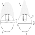
- Fig. 1 depicts results of a helmet air trip resistance test conducted to validate the air trip concept in accordance with an illustrative embodiment. Specifically, the upper portion of Fig. 1 depicts the effects of oncoming air contacting a smooth helmet 100, which does not include an air trip. In the actual tests, the oncoming air (referred to as air or airflow for simplicity) was actually a smoke/air gas mixture that was used so that the gaseous response could be visualized. Additionally, the test was conducted in an air tunnel such that a rate of the oncoming airflow could be precisely controlled.
- the smooth helmet 100 is shown as a top view that depicts the dome (top) portion of the outer shell of the helmet. The oncoming airflow is generally laminar prior to contacting the smooth helmet 100.
- the transition region 105 (shown via a dashed line) is essentially a continuous region that runs in a ring about a perimeter of the smooth helmet 100. As shown, the transition region 105 is at or slightly forward of the center of the smooth helmet 100.
- the turbulent airflow generated at the transition region 105 separates from the smooth helmet 100 at a separation region 110 (also shown with a dashed line), which is located to the rear (i.e., with the initial point of contact of the airflow and the smooth helmet 100 being forward) of the transition region 105.
- the separation region 110 is also a continuous region that runs in a ring about a perimeter of the smooth helmet 100.
- the upper portion of Fig. 1 also depicts a wake 115 generated by the turbulent air flow that separated from the smooth helmet 100. As shown, the generated wake 115 is larger than a diameter of the smooth helmet 100. Such a large wake creates significant drag, which in the context of a cycling helmet, can significantly reduce the speed of the rider.
- the lower portion of Fig. 1 depicts an air trip helmet 125 of the same general size/shape/mass/etc. as the smooth helmet 100.
- the air trip helmet 125 includes an air trip 130 out an outer surface thereof.
- the air trip 130 is a continuous groove that runs in a ring about a perimeter of the air trip helmet 125.
- the air trip 130 is positioned at an angle relative to an outer surface of the air trip helmet 125 such that it is perpendicular to the airflow.
- perpendicular it is meant that a line perpendicular to and extending outward from a center of the bottom of the groove (that forms the air trip 130) is perpendicular to the airflow.
- the air trip 130 is located forward of the previously identified natural transition region 105 such that the air trip 130 is closer to the initial point of contact between the airflow and the air trip helmet 125 than is the natural transition region of the air trip helmet 125.
- the oncoming air is tripped (i.e., caused to transition from laminar flow to turbulent flow) earlier than it otherwise would have been.
- Being caused to transition at this more forward location causes a more rearward separation region 135 (shown via dashed line) for the air trip helmet 125, as compared to the smooth helmet 100 depicted in the upper portion of Fig. 1 .
- the more rearward separation region 135 results in a wake 140 that is significantly smaller than the wake generated by the smooth helmet 100.
- the air trip helmet 125 has significantly less drag than the smooth helmet 100, which in the context of a cycling helmet can increase the rider speed and result in a more comfortable experience.
- the inventors determined that placing the air trip forward of the natural transition point of the helmet resulted in the greatest reduction in wake.
- the inventors also determined through experimentation that a shelf or ledge (i.e., drop off) formed in the outer shell of the helmet does not provide anywhere near the same level of wake reduction as the proposed air trip in the form of a continuous groove. The reason for this is that a shelf/ledge does not cause the laminar airflow to transition from laminar flow to turbulent flow at a location that is forward of the normal/natural laminar-to-turbulent transition region.
- a shelf/ledge does appear to move the laminar-to-turbulent transition region (on the helmet) of the airflow forward, and therefore does not significantly decrease wake or drag.
- the inventors determined that an air trip that does not fully extend from the bottom of the first side of the helmet to the bottom of the second side of the helmet is much less effective.
- the inventors also determined through experimentation that an air vent or other through hole in the helmet does not have the same effect as the proposed air trip because such vents/holes do not alter laminar-to-turbulent transition region of the helmet in a way that decreases wake.
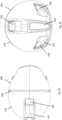
- Figs. 2A-2H depict various views of a helmet 200 with an air trip 205 to provide reduced wake and drag, and increased speed.
- Fig. 2A is a plan view of the helmet with the air trip 205 in accordance with an illustrative embodiment.
- Fig. 2B is a rear view of the helmet 200 in accordance with an illustrative embodiment.
- Fig. 2C is a bottom (or interior) view of the helmet 200 in accordance with an illustrative embodiment.
- Fig. 2D is a side view of the helmet 200 in accordance with an illustrative embodiment.
- Fig. 2E is a bottom right side perspective view of the helmet 200 in accordance with an illustrative embodiment.
- Fig. 2A is a plan view of the helmet with the air trip 205 in accordance with an illustrative embodiment.
- Fig. 2B is a rear view of the helmet 200 in accordance with an illustrative embodiment.
- Fig. 2C is
- FIG. 2F is a bottom left side perspective view of the helmet 200 in accordance with an illustrative embodiment.
- Fig. 2G is a bottom rear perspective view of helmet 200 showing a center line A in accordance with an illustrative embodiment.
- Fig. 2H is a cross-sectional view of the helmet 200 along the center line A of Fig. 2G in accordance with an illustrative embodiment.
- the air trip 205 makes the helmet 200 more aerodynamic to help the rider go faster.
- the air trip 205 is a groove recessed into the helmet 200.
- the air trip 205 is located just in front of where the air would normally transition from laminar to turbulent flow (i.e., in front of the normal or natural laminar-to-turbulent airflow transition region of the helmet). Additionally, the air trip 205 is positioned perpendicular to the airflow direction.
- the air trip 205 works as a boundary layer control device to force the air to transition from laminar flow to turbulent flow at the groove. This transition adds energy to the air flow, allowing the air flow to stay attached further back on the helmet and reducing the size of the wake.
- the air trip 205 also makes the helmet 200 more aerodynamic in different rider positions and different rider speeds.
- the air trip 205 can be designed to provide the greatest reduction of drag at a speed of 26 miles per hour (mph).
- the air trip 205 may be designed to provide the greatest reduction of drag at a different speed, such as 20 mph, 22 mph, 24 mph, 28 mph, etc.
- the air trip 205 is formed in an outer shell 210 of the helmet 200.
- the outer shell 210 of the helmet 200 can be made from plastic, resin, fiber, polycarbonate, polyethylene, terephthalate (PET), acrylonitrile butadiene styrene, polyethylene (PE), polyvinyl chloride (PVC), vinyl nitrile (VN), fiberglass, carbon fiber, or other similar material.
- the outer shell 210 provides a rigid outer layer.
- the outer shell 210 can be formed through stamping, molding, vacuum forming, or any other known fabrication technique.
- Mounted to the outer shell 210 is an energy absorbing layer 215.
- the energy absorbing layer 215 can be formed from a closed cell foam such as expanded polystyrene (EPS) in one embodiment.
- the energy absorbing layer 215 can be formed from an energy absorbing layer with multi-directional flexibility.
- Such an energy absorbing material which can be made from polycarbonate or a similar material, is able to bend, compress, stretch, and shift in multiple directions without shearing.
- the energy absorbing layer 215 can be formed in part by a closed cell foam layer and in part by one or more energy absorbing inserts that are supported by the closed cell foam layer.
- the energy absorbing layer 215 can be mounted to the outer shell 210 via an adhesive, through co-molding, etc.
- the energy absorbing layer 215 includes one or more embedded mounts (e.g., mushroom plugs, threaded openings, clips, etc.) that are used to secure a fit system to the helmet 200.
- the fit system can include a yoke and straps for securing the helmet 200 to a user's head.
- the helmet 200 also includes vents 220 that are used to assist with ventilation and rider comfort. As shown, the vents 220 are formed in the outer shell 210 of the helmet at locations positioned to the rear of the air trip 205. As best depicted in Fig.
- the vents 220 formed in the helmet 200 include a vent positioned on the top center of the helmet 200, a vent positioned on the back center of the helmet 200, a vent positioned on the back left of the helmet 200, and a vent positioned on the back right of the helmet 200.
- fewer or additional vents may be used, and the vent(s) may be positioned at different locations on the helmet 200.
- Fig. 3A is a close-up cross-sectional view of the air trip in accordance with an illustrative embodiment. While Fig. 3A includes example dimensions (in millimeters) that were determined to be optimal through experimentation and testing, it is to be understood that different dimensions may be used for the air trip in alternative embodiments.
- the air trip has a u-shaped cross-section with a curved bottom that flattens out at its center, a first curved transition 315 from a front portion of the helmet to the air trip, and a second curved transition 320 from a rear portion of the helmet to the air trip.
- An example radius of curvature of the curved bottom of the air trip can be 2.5 mm.
- a radius of curvature of the first curved transition 315 and the second curved transition 320 can be 2.25 mm. In alternative embodiments, different radii of curvature may be used.
- all 3 radii of curvature may be the same, at 2.25 mm, 2.5 mm, or a different value such as 1.5 mm, 2 mm, 2.75 mm, 3 mm, 3.5 mm, etc.
- the first curved transition 315 can have a radius of curvature that differs from that of the second curved transition 320.
- a depth of the groove that forms the air trip can be 4.5 mm in one embodiment, and an inner width of the groove can be 5 mm.
- an outer width between the start of the first curved transition 315 and the start of the second curved transition 320 can be 10.2 mm.
- different depths e.g., 3.5 mm, 3.75 mm.
- inner widths e.g., 4 mm, 4.5 mm, 5.5 mm, 6 mm, etc.
- outer widths e.g., 9 mm, 9.5 mm, 10.5 mm, 11 mm, 12 mm, etc.
- the groove that forms the air trip is positioned at an angle relative to an exterior surface of the outer shell.
- the angle at which the air trip is positioned can be based at least in part on rider style, and different helmets can have air trips positioned at different angles to accommodate different riders.
- the angle of the air trip is controlled such that the air trip is perpendicular to oncoming air while the rider is in position to operate the bicycle.
- the angle of the air trip can be conceptualized by initially considering a tangent line 300 that is tangent to a bottom of the center of the air trip and a line 305 that extends perpendicular to the tangent line and that includes the center of the bottom of the air trip.
- the line 305 intersects a line 310 that extends along the outer surface of the outer shell from a start of the first curved transition 315 of the air trip to a start of the second curved transition 320 of the air trip.
- the angle between the line 305 and the line 310 is 90 degrees, which means that the air trip has an angle of 90 degrees relative to the outer surface of the outer shell.
- the angle of the air trip can be altered to ensure that the oncoming air contacts the air trip in a perpendicular manner.
- the air trip can be positioned at an angle such that the tangent line 300 and the line 305 (perpendicular to the tangent line) from Fig. 3A are both rotated in a counterclockwise direction such that the air trip angle ⁇ (i.e., the angle between the line 305 and the line 310) is less than 90 degrees.
- Fig. 3B depicts a configuration in which the air trip angle is less than 90 degrees in accordance with an illustrative embodiment.
- the air trip angle ⁇ can be 70 degrees, 75 degrees, 80 degrees, 85 degrees, etc.
- the air trip can be positioned such that the tangent line 300 and the line 305 (perpendicular to the tangent line) from Fig. 3A are both rotated in a clockwise direction such that the air trip angle ⁇ (i.e., the angle between the line 305 and the line 310) is greater than 90 degrees.
- Fig. 3C depicts a configuration in which the air trip angle is greater than 90 degrees in accordance with an illustrative embodiment. In such an embodiment, the air trip angle ⁇ can be 95 degrees, 100 degrees, 110 degrees, 115 degrees, etc.
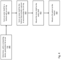
- Fig. 4 is a flow diagram depicting operations performed to make a helmet with an air trip in accordance with an illustrative embodiment. In alternative embodiments, fewer, additional, and/or different operations may be performed. Also, the use of a flow diagram is not meant to be limiting with respect to the order of operations performed.
- a computing device is used to determine parameters for an air trip to be used on a helmet.
- the computing device can include a processor, a memory, a user interface (e.g., mouse, keyboard, display) to receive user commands and present results, a transceiver (e.g., receiver and transmitter) for communication with remote devices and systems, etc.
- the memory can be used to store computer-readable instructions that act to execute any of the design, testing, and analysis operations described herein.
- the processor can execute the computer-readable instructions to implement the operations.
- the parameters for the air determined by the computer can include a location of the air trip on the helmet (which can be determined based on an identified location of the natural laminar-to-turbulent airflow transition region on the helmet), an inner width of the air trip, an outer width of the air trip, a depth of the air trip, a radius of curvature of a curved bottom of the air trip, a radius of curvature of a first curved transition of the air trip, a radius of curvature of a second curved transition of the air trip, etc.
- the parameters can also include an angle of the air trip, as discussed herein.
- the parameters can be determined through computational fluid dynamic analyses, wind tunnel testing, trial-and-error testing, etc.
- the parameters can be based on helmet shape, a determined riding/head position for a given cyclist (or for a group of cyclists that all ride in similar positions), the type of bicycle with which the helmet is intended to be used, a desired riding speed, etc.
- an outer shell for the helmet is formed with the air trip, based on the determined parameters for the air trip.
- the outer shell is formed via molding, and the air trip is molded into the outer shell as a continuous groove that extends from a bottom left side of the helmet to a bottom right side of the helmet.
- the air trip is positioned on the helmet forward of a natural laminar-to-turbulent flow transition region of the helmet.
- a thickness of the outer shell remains the same over the entire outer shell, including at the air trip.
- the outer shell may not be used, and the helmet can be formed using just the energy absorbing layer with the air trip formed in the energy absorbing layer.
- an energy absorbing layer for the helmet is formed such that the energy absorbing layer includes a groove to accommodate the air trip.
- the groove in the energy absorbing layer receives the air trip such that the energy absorbing layer and outer shell can be tightly secured to one another.
- the energy absorbing layer can be formed from molding, or using any other technique known in the art.
- the energy absorbing layer can include one or more embedded mounts (mushroom plugs, clips, etc.) that can be used to secure items (e.g., a fit system) to the helmet.
- the energy absorbing layer can also include multiple materials in some embodiments, such as a closed cell foam layer that surrounds inserts of energy absorbing material.
- the energy absorbing layer is mounted to the outer shell.
- the mounting can be performed using an adhesive, or any other technique.
- a fit system is mounted to the helmet such that the helmet can be secured to the rider's head.
- the fit system can be mounted by attaching it to the mounts embedded in the energy absorbing layer.
Landscapes
- Physics & Mathematics (AREA)
- Fluid Mechanics (AREA)
- Helmets And Other Head Coverings (AREA)
Applications Claiming Priority (1)
| Application Number | Priority Date | Filing Date | Title |
|---|---|---|---|
| US17/733,061 US20230346066A1 (en) | 2022-04-29 | 2022-04-29 | Helmet with an air trip |
Publications (3)
| Publication Number | Publication Date |
|---|---|
| EP4268655A1 true EP4268655A1 (de) | 2023-11-01 |
| EP4268655C0 EP4268655C0 (de) | 2025-11-19 |
| EP4268655B1 EP4268655B1 (de) | 2025-11-19 |
Family
ID=86272213
Family Applications (1)
| Application Number | Title | Priority Date | Filing Date |
|---|---|---|---|
| EP23170369.5A Active EP4268655B1 (de) | 2022-04-29 | 2023-04-27 | Helm mit luftweg |
Country Status (2)
| Country | Link |
|---|---|
| US (1) | US20230346066A1 (de) |
| EP (1) | EP4268655B1 (de) |
Families Citing this family (4)
| Publication number | Priority date | Publication date | Assignee | Title |
|---|---|---|---|---|
| USD1084608S1 (en) * | 2021-12-28 | 2025-07-22 | Specialized Bicycle Components, Inc. | Bicycle helmet |
| JP1755206S (ja) * | 2023-05-30 | 2023-10-12 | ヘルメット | |
| USD1083308S1 (en) * | 2023-07-11 | 2025-07-15 | Poc Sweden Ab | Helmet |
| USD1108026S1 (en) * | 2024-05-31 | 2025-12-30 | Oakley, Inc. | Helmet |
Citations (3)
| Publication number | Priority date | Publication date | Assignee | Title |
|---|---|---|---|---|
| FR2645719A1 (fr) * | 1989-04-18 | 1990-10-19 | Guichard Philippe | Casque aerodynamique |
| DE9209357U1 (de) * | 1992-07-11 | 1992-09-10 | Institut für Forschung und Entwicklung von Sportgeräten (FES) e.V., O-1160 Berlin | Sturzhelm, insbesondere für Radsport |
| US5271102A (en) * | 1990-06-11 | 1993-12-21 | Feuling James J | Helmet with fluid flow termination surface |
Family Cites Families (4)
| Publication number | Priority date | Publication date | Assignee | Title |
|---|---|---|---|---|
| US3280402A (en) * | 1964-10-01 | 1966-10-25 | Schuberth Werk Kg Fa | Protective headgear |
| US4586197A (en) * | 1985-01-31 | 1986-05-06 | Hubbard Stirling J | Aerodynamically stabilized motorcyclist helmet |
| US5023958A (en) * | 1989-09-01 | 1991-06-18 | Rotzin Stephen A | Aerodynamic bicycle helmet |
| US20130340151A1 (en) * | 2012-06-22 | 2013-12-26 | Specialized Bicycle Components, Inc | Bicycle helmet with vent |
-
2022
- 2022-04-29 US US17/733,061 patent/US20230346066A1/en active Pending
-
2023
- 2023-04-27 EP EP23170369.5A patent/EP4268655B1/de active Active
Patent Citations (3)
| Publication number | Priority date | Publication date | Assignee | Title |
|---|---|---|---|---|
| FR2645719A1 (fr) * | 1989-04-18 | 1990-10-19 | Guichard Philippe | Casque aerodynamique |
| US5271102A (en) * | 1990-06-11 | 1993-12-21 | Feuling James J | Helmet with fluid flow termination surface |
| DE9209357U1 (de) * | 1992-07-11 | 1992-09-10 | Institut für Forschung und Entwicklung von Sportgeräten (FES) e.V., O-1160 Berlin | Sturzhelm, insbesondere für Radsport |
Also Published As
| Publication number | Publication date |
|---|---|
| EP4268655C0 (de) | 2025-11-19 |
| EP4268655B1 (de) | 2025-11-19 |
| US20230346066A1 (en) | 2023-11-02 |
Similar Documents
| Publication | Publication Date | Title |
|---|---|---|
| EP4268655B1 (de) | Helm mit luftweg | |
| EP2442682B1 (de) | Aerodynamische abdeckung für fahrradpedal und pedalplatte | |
| CN110785096B (zh) | 头盔 | |
| US9585432B2 (en) | Sport helmet | |
| US10918153B2 (en) | Helmet with airflow ventilation through an earpad | |
| EP0261299B1 (de) | Schutzhelm | |
| EP3446585A1 (de) | Clip-freie helmvisiere | |
| EP1754422B1 (de) | Lüftungselement für Sturzhelm, das sich beim Sturz vom Helm löst | |
| JP2017509809A (ja) | 適応性フィットヘルメット、及び顧客の頭部にヘルメットをフィットさせるための方法 | |
| CN204949670U (zh) | 一种新型头盔 | |
| EP3138429B1 (de) | Aerodynamische steuerungsvorrichtung und helm damit | |
| US20130340151A1 (en) | Bicycle helmet with vent | |
| EP1839510A1 (de) | Befestigungsvorrichtung für einen Helmgurt | |
| CN110352020B (zh) | 集成肩垫的头盔 | |
| US20170143069A1 (en) | Helmet providing position feedback | |
| EP4136997A1 (de) | Helm mit verstellbarem sitzsystem | |
| US20240334996A1 (en) | Protective helmet | |
| US11103024B2 (en) | Helmet with magnetically-operated air vent | |
| US20150033456A1 (en) | Helmet | |
| EP2692617B1 (de) | Sattelfahrzeug | |
| JP3006981U (ja) | ヘルメット | |
| JP2023059843A (ja) | ヘルメット | |
| JPS6359406A (ja) | 自転車用ヘルメツト | |
| JPH1150327A (ja) | 乗車用ヘルメットの換気装置 | |
| JPH10331021A (ja) | ヘルメット |
Legal Events
| Date | Code | Title | Description |
|---|---|---|---|
| PUAI | Public reference made under article 153(3) epc to a published international application that has entered the european phase |
Free format text: ORIGINAL CODE: 0009012 |
|
| STAA | Information on the status of an ep patent application or granted ep patent |
Free format text: STATUS: THE APPLICATION HAS BEEN PUBLISHED |
|
| AK | Designated contracting states |
Kind code of ref document: A1 Designated state(s): AL AT BE BG CH CY CZ DE DK EE ES FI FR GB GR HR HU IE IS IT LI LT LU LV MC ME MK MT NL NO PL PT RO RS SE SI SK SM TR |
|
| STAA | Information on the status of an ep patent application or granted ep patent |
Free format text: STATUS: REQUEST FOR EXAMINATION WAS MADE |
|
| 17P | Request for examination filed |
Effective date: 20240429 |
|
| RBV | Designated contracting states (corrected) |
Designated state(s): AL AT BE BG CH CY CZ DE DK EE ES FI FR GB GR HR HU IE IS IT LI LT LU LV MC ME MK MT NL NO PL PT RO RS SE SI SK SM TR |
|
| GRAP | Despatch of communication of intention to grant a patent |
Free format text: ORIGINAL CODE: EPIDOSNIGR1 |
|
| STAA | Information on the status of an ep patent application or granted ep patent |
Free format text: STATUS: GRANT OF PATENT IS INTENDED |
|
| INTG | Intention to grant announced |
Effective date: 20250625 |
|
| GRAS | Grant fee paid |
Free format text: ORIGINAL CODE: EPIDOSNIGR3 |
|
| GRAA | (expected) grant |
Free format text: ORIGINAL CODE: 0009210 |
|
| STAA | Information on the status of an ep patent application or granted ep patent |
Free format text: STATUS: THE PATENT HAS BEEN GRANTED |
|
| AK | Designated contracting states |
Kind code of ref document: B1 Designated state(s): AL AT BE BG CH CY CZ DE DK EE ES FI FR GB GR HR HU IE IS IT LI LT LU LV MC ME MK MT NL NO PL PT RO RS SE SI SK SM TR |
|
| REG | Reference to a national code |
Ref country code: CH Ref legal event code: F10 Free format text: ST27 STATUS EVENT CODE: U-0-0-F10-F00 (AS PROVIDED BY THE NATIONAL OFFICE) Effective date: 20251119 Ref country code: GB Ref legal event code: FG4D |
|
| REG | Reference to a national code |
Ref country code: DE Ref legal event code: R096 Ref document number: 602023008662 Country of ref document: DE |
|
| REG | Reference to a national code |
Ref country code: IE Ref legal event code: FG4D |
|
| U01 | Request for unitary effect filed |
Effective date: 20251120 |
|
| U07 | Unitary effect registered |
Designated state(s): AT BE BG DE DK EE FI FR IT LT LU LV MT NL PT RO SE SI Effective date: 20251127 |
|
| PG25 | Lapsed in a contracting state [announced via postgrant information from national office to epo] |
Ref country code: ES Free format text: LAPSE BECAUSE OF FAILURE TO SUBMIT A TRANSLATION OF THE DESCRIPTION OR TO PAY THE FEE WITHIN THE PRESCRIBED TIME-LIMIT Effective date: 20251119 |
|
| PG25 | Lapsed in a contracting state [announced via postgrant information from national office to epo] |
Ref country code: NO Free format text: LAPSE BECAUSE OF FAILURE TO SUBMIT A TRANSLATION OF THE DESCRIPTION OR TO PAY THE FEE WITHIN THE PRESCRIBED TIME-LIMIT Effective date: 20260219 |
|
| PG25 | Lapsed in a contracting state [announced via postgrant information from national office to epo] |
Ref country code: HR Free format text: LAPSE BECAUSE OF FAILURE TO SUBMIT A TRANSLATION OF THE DESCRIPTION OR TO PAY THE FEE WITHIN THE PRESCRIBED TIME-LIMIT Effective date: 20251119 |
|
| PG25 | Lapsed in a contracting state [announced via postgrant information from national office to epo] |
Ref country code: RS Free format text: LAPSE BECAUSE OF FAILURE TO SUBMIT A TRANSLATION OF THE DESCRIPTION OR TO PAY THE FEE WITHIN THE PRESCRIBED TIME-LIMIT Effective date: 20260219 |
|
| PG25 | Lapsed in a contracting state [announced via postgrant information from national office to epo] |
Ref country code: IS Free format text: LAPSE BECAUSE OF FAILURE TO SUBMIT A TRANSLATION OF THE DESCRIPTION OR TO PAY THE FEE WITHIN THE PRESCRIBED TIME-LIMIT Effective date: 20260319 |