EP4265864A1 - Accessoire d'entretoisement - Google Patents
Accessoire d'entretoisement Download PDFInfo
- Publication number
- EP4265864A1 EP4265864A1 EP23168539.7A EP23168539A EP4265864A1 EP 4265864 A1 EP4265864 A1 EP 4265864A1 EP 23168539 A EP23168539 A EP 23168539A EP 4265864 A1 EP4265864 A1 EP 4265864A1
- Authority
- EP
- European Patent Office
- Prior art keywords
- rod
- sealing element
- accessory
- bracing
- bracing accessory
- Prior art date
- Legal status (The legal status is an assumption and is not a legal conclusion. Google has not performed a legal analysis and makes no representation as to the accuracy of the status listed.)
- Granted
Links
Images

Classifications
-
- E—FIXED CONSTRUCTIONS
- E04—BUILDING
- E04B—GENERAL BUILDING CONSTRUCTIONS; WALLS, e.g. PARTITIONS; ROOFS; FLOORS; CEILINGS; INSULATION OR OTHER PROTECTION OF BUILDINGS
- E04B1/00—Constructions in general; Structures which are not restricted either to walls, e.g. partitions, or floors or ceilings or roofs
- E04B1/38—Connections for building structures in general
- E04B1/388—Separate connecting elements
-
- E—FIXED CONSTRUCTIONS
- E04—BUILDING
- E04F—FINISHING WORK ON BUILDINGS, e.g. STAIRS, FLOORS
- E04F13/00—Coverings or linings, e.g. for walls or ceilings
- E04F13/07—Coverings or linings, e.g. for walls or ceilings composed of covering or lining elements; Sub-structures therefor; Fastening means therefor
- E04F13/08—Coverings or linings, e.g. for walls or ceilings composed of covering or lining elements; Sub-structures therefor; Fastening means therefor composed of a plurality of similar covering or lining elements
- E04F13/0801—Separate fastening elements
- E04F13/0803—Separate fastening elements with load-supporting elongated furring elements between wall and covering elements
- E04F13/0805—Separate fastening elements with load-supporting elongated furring elements between wall and covering elements with additional fastening elements between furring elements and the wall
- E04F13/0807—Separate fastening elements with load-supporting elongated furring elements between wall and covering elements with additional fastening elements between furring elements and the wall adjustable perpendicular to the wall
-
- E—FIXED CONSTRUCTIONS
- E04—BUILDING
- E04B—GENERAL BUILDING CONSTRUCTIONS; WALLS, e.g. PARTITIONS; ROOFS; FLOORS; CEILINGS; INSULATION OR OTHER PROTECTION OF BUILDINGS
- E04B1/00—Constructions in general; Structures which are not restricted either to walls, e.g. partitions, or floors or ceilings or roofs
- E04B1/62—Insulation or other protection; Elements or use of specified material therefor
- E04B1/74—Heat, sound or noise insulation, absorption, or reflection; Other building methods affording favourable thermal or acoustical conditions, e.g. accumulating of heat within walls
- E04B1/76—Heat, sound or noise insulation, absorption, or reflection; Other building methods affording favourable thermal or acoustical conditions, e.g. accumulating of heat within walls specifically with respect to heat only
- E04B1/7675—Insulating linings for the interior face of exterior walls
-
- E—FIXED CONSTRUCTIONS
- E04—BUILDING
- E04F—FINISHING WORK ON BUILDINGS, e.g. STAIRS, FLOORS
- E04F13/00—Coverings or linings, e.g. for walls or ceilings
- E04F13/07—Coverings or linings, e.g. for walls or ceilings composed of covering or lining elements; Sub-structures therefor; Fastening means therefor
- E04F13/08—Coverings or linings, e.g. for walls or ceilings composed of covering or lining elements; Sub-structures therefor; Fastening means therefor composed of a plurality of similar covering or lining elements
- E04F13/14—Coverings or linings, e.g. for walls or ceilings composed of covering or lining elements; Sub-structures therefor; Fastening means therefor composed of a plurality of similar covering or lining elements stone or stone-like materials, e.g. ceramics concrete; of glass or with an outer layer of stone or stone-like materials or glass
Definitions
- the present invention generally relates to the lining of walls for insulation or aesthetic purposes. It relates more particularly to a bracing accessory arranged between a wall to be lined and a facing, in order to keep the latter at a distance from the wall to be lined.
- a facing 2 is attached to a lining frame which is itself fixed to structural elements 1A of the wall 1 to be lined, at a given distance from it.
- a thermal and/or acoustic insulation pad (often called insulation complex) is inserted between the wall 1 to be lined and the facing 2.
- the insulation pad typically includes, on the one hand, one or more layers of an insulating product 3, such as mineral wool (glass, rock), a biosourced insulation such as wood fiber or a cellular reflective insulation, in the form of unfoldable panels or rolls and, on the other hand, at least one sealing membrane 4, that is to say a vapor barrier and/or vapor barrier membrane.
- This membrane 4 is most often inserted between the insulation product 3 and the facing 2, typically attached to the facing, and/or possibly inserted between two layers of the insulating product. It can alternatively be integral with the insulating product 3, or attached separately between the latter and the facing 2.
- bracing accessories 5 commonly called “hangers” for ceiling and roof lining, and “supports » for wall lining.
- Each bracing accessory comprises a main body in the form of a rod 5A extending transversely to the wall 1 to be lined and to the facing 2.
- a first end of the accessory is provided with a cantilever fixing 5B to A structural element 1A of the wall 1 to be lined, while a second end is provided with a fixing 5C to a furring 6 of a lining frame.
- the insulation gasket is plugged onto the rods 5A of the bracing accessories 5, which causes multiple piercing of the insulation product 3 and the membrane 4.
- This piercing is particularly detrimental in that concerns the membrane 4, because its sealing function, permanent or selective, is then altered.
- the piercing of the membrane 4 can also constitute an incipient tear likely to propagate if tension is exerted on the membrane.
- the publication FR2925929A1 describes the implementation of a pair of jaws which, after locking by clipping in a groove arranged at the second end of the rod of a hanger, grip a sealing membrane near its point of perforation by the rod , in order to ensure the continuity of the seal.
- Such a hanger although efficient, nevertheless has some disadvantages, including the irreversible nature of its attachment, unless the jaws are destroyed.
- the proposed technique aims to provide a technical solution to the drawbacks described above. More particularly, in at least one embodiment, the proposed technique relates to a bracing accessory adapted to fixing at least one insulating product on a wall to be lined, comprising a rod whose first end is adapted to be fixed to a structural element of said wall, and a second end of which is adapted to pass right through said insulating product and a sealing membrane, said bracing accessory being characterized in that it comprises an element of seal comprising a hole, preferably through, the periphery of which has a shape complementary to the section of the rod and is made up of an elastic material adapted to allow reversible elastic fixing by friction of said sealing element on the rod and in that said rod is of substantially planar shape, preferably metallic.
- reversible elastic fixation designates the non-definitive joining of one part to another by elastic deformation.
- the latter is either inserted directly onto the rod (mineral wool, cellular reflective insulation), or attached to the latter (rigid panels of wood fiber insulation), so that the rod is slipped between two consecutive panels of insulation.
- the second end of the rod passes right through said insulating product, within the meaning of the invention.
- the rod preferably passes through the sealing element right through, at the level of the hole provided for this purpose.
- an operator inserts the sealing element around the rod via the hole provided for this purpose, then slides said sealing element against the membrane , the elastic properties of the sealing element allowing it to deform elastically to fit the periphery of the rod while exerting a compressive force on the latter, under the effect of the elastic return.
- the sealing element is then elastically fixed on the rod by opposing resistance by friction, that is to say of a tribological nature, to its withdrawal.
- Such a sealing element nevertheless remains removable if sufficient traction force is exerted by an operator.
- the elastic nature of the material present at the interface between the rod and the sealing element allows the latter to perfectly match the surface of the rod, and thus to maximize the contact surface and the sealing properties sought after. this interface.
- the invention is thus based on an inventive concept consisting of providing a bracing element which is both easy to use and removable, while providing satisfactory airtightness around the rod.
- the implementation of a reversible elastic fixing of the sealing accessory on the rod also makes it possible to adapt the positioning of the sealing accessory according to the needs of the operator, for example the thickness of the insulation product(s) and especially the final positioning of the waterproofing membrane. In other words, it is not necessary at the time of manufacturing the bracing accessory to predefine a fixing zone of the sealing element on the rod.
- said rod is said to have a "substantially planar" shape in the sense that it extends mainly in the same theoretical plane, while preferably presenting slight folds at the level of its lateral edges and/or the embossing lines, in order to increase its rigidity.
- a rod of substantially flat shape has the advantage of offering an increased contact surface to a sealing accessory, thus facilitating the implementation of a fixing with satisfactory sealing and reliability.
- said sealing element comprises a rise in which said hole is formed, and which preferably extends along the axis of the rod over a distance greater than 2 mm, preferably greater than 5 mm, preferably greater than 10 mm.
- said rise extends from a flat base, preferably of circular, oval, square or diamond shape, preferably coated with an adhesive and/or gripping coating, said flat base being adapted for come into abutment against the sealing membrane when inserting the sealing element onto the rod.
- the elastic material constituting at least the periphery of the hole, if not the entirety of said sealing element has a Shore A hardness of between 20 and 100, preferably between 30 and 80, and preferably belongs to the group including elastomers, for example rubber, butyl, compounds including styrene, butadiene or ethylene, compounds including polyester, polyproprylene or EPDM, polyurethane or thermoplastic olefins.
- elastomers for example rubber, butyl, compounds including styrene, butadiene or ethylene, compounds including polyester, polyproprylene or EPDM, polyurethane or thermoplastic olefins.
- the entirety of said sealing element is made up of said elastic material.
- the manufacture of such a one-piece sealing element is easier to carry out, in comparison with a sealing element formed from a plurality of different materials.
- said sealing element comprises at least one so-called rigid material which has a flexural modulus greater than 100 MPa, preferably greater than 1000 MPa, and preferably belongs to the group comprising metals and thermoplastics, and which constitutes said flat base and/or the periphery of the rise.
- said sealing element comprises a reversible locking member of said sealing element on the rod, preferably a key.
- an additional reversible locking member makes it possible, in addition to the reversible elastic fixation by friction already provided by the sealing element at the level of its hole, to reinforce the fixation of the sealing element on the rod, so that it can, for example, better support the weight of the insulating product.
- said sealing element is formed of two jaws adapted to grip the rod in a reversible elastic fixing configuration by friction of said sealing element on the rod.
- the two jaws are pivotally linked.
- the two jaws are two separate pieces, preferably linked by a hinge.
- the two jaws are part of the same part which has a folding line adapted to allow the pivoting of one jaw relative to the other.
- said rod comprises at its second end a tip, which is preferentially foldable between a so-called plug-in configuration, in which said tip is arranged in the extension of the rod, and a configuration in which all or part of the tip is tilted outside the axis of the rod.
- the tip at the end of the rod makes it easier to plug in the insulating product(s) and the membrane. Its post-skewering lateral tilting, however, makes it possible to avoid exposing an operator to this tip, once installed, and possibly to allow the clipping of a furring.
- said rod comprises at its second end a device for fixing to a fur, which preferably comprises two grooves arranged at the periphery of the rod, in a theoretical plane orthogonal to the axis of the rod.
- the rod of the bracing accessory can thus be fixed directly to a furring, in order to ensure a satisfactory mechanical connection, and independent of the sealing element.
- said rod comprises at least one member for holding the insulating product which projects from the rod, and which preferably comprises a tooth or a flap.
- Such a holding member makes it possible to retain the insulating panel, for example when it tends to slide on the rod under its own weight.
- said rod comprises a rough surface adapted to come into contact with the periphery of the hole of said sealing element.
- said bracing accessory comprises a cup adapted to be arranged between said insulating product and the membrane and to form a counter-support to said sealing element in order to pinch the membrane around its insertion opening .
- said cup is adapted to be mounted in a sliding pivot around the rod.
- said cup is fixed to the rod by a reversible elastic fixation by friction and/or a reversible locking member.
- the invention also relates to an assembly comprising a wall to be lined provided with a structural element to which is fixed at least one such bracing accessory, which passes right through at least one insulating product and at least one membrane waterproofing.
- an insulating panel is pre-equipped with a sealing membrane or is devoid of one, said membrane then being plugged separately onto the rod of the bracing accessory.
- said at least one bracing accessory is attached to a furring, itself attached to a facing.
- said assembly comprises at least one acoustic damping member at the interface between the bracing accessory and the fur.
- said acoustic damping member is arranged between the end of the rod close to its bend and the fur, in order to limit the propagation of sound waves and possible clicking noises between the rod and fur.
- the invention also relates to a method of fixing at least one insulating product on a wall to be lined, comprising at least the following steps, in this order:
- a sealing membrane is inserted onto the second end of the rod, and the sealing element of said bracing accessory.
- the invention also relates to a method of lining a wall, comprising the implementation of a method of fixing at least one such insulating product and the mounting of at least one furring on said bracing accessory , and a facing on said fur.
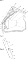
- FIG. 1 there figure 1 is a perspective view, cut away, of the interior of a building whose roof and walls are insulated by means of a lining assembly known from the state of the art,
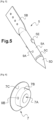
- FIG. 2 there figure 2 is a schematic perspective view of the rod of a bracing accessory according to a first embodiment of the invention
- FIG. 3 is a schematic perspective view of a sealing element of a bracing accessory according to a first embodiment of the invention
- FIG. 4 there Figure 4 is a schematic perspective view of an assembly formed of a wall to be lined, a bracing accessory and a furring, according to a first embodiment of the invention
- FIG. 5 is a schematic perspective view of the rod of a bracing accessory according to a second embodiment of the invention.
- FIG. 6 is a schematic perspective view of a sealing element of a bracing accessory according to a second embodiment of the invention.
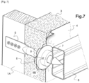
- FIG. 7 is a schematic perspective view of an assembly formed of a wall to be lined, a bracing accessory and a furring, according to a second embodiment of the invention.
- FIGS. 2 And 3 respectively represent a rod 5A and a sealing element 7 of a bracing accessory 5 according to a first embodiment of the invention in which the rod 5A of the accessory 5 is of substantially planar shape, and is of metallic.
- Figure 4 represents an assembly formed by a wall to be lined 1, such a bracing accessory 5 and a furring 6.
- a first end of the rod 5A of the bracing accessory 5 is first fixed to a structural element 1A of the wall 1. More precisely, and as illustrated by Figure 4 , this fixing is implemented via perforations made in a plate-shaped portion 5B of the rod 5A, in which screws are engaged.
- such fixing of said rod to said structural element can be ensured by any equivalent fixing system, for example by means of a head provided at said first end of the rod, and adapted to be fixed in a furring itself secured to the wall to be lined.
- bracing accessory 5 is fixed to the wall 1, and as illustrated by the Figure 4 , we place at least one insulating product 3 against the wall 1, so that said rod 5A passes right through the latter.
- the insulating product 3 is either plugged directly onto the rod 2A, or attached to the latter, so that the rod 2A is slipped between two consecutive insulating panels 3.
- Figure 4 leaves the field open to these two alternative embodiments, the apparent section of the insulating product 3 having to be considered as a cut in the first case, or as the edge of the insulating product 3 in the second case, to which the rod would be attached.
- This tooth can be in the thickness of the insulating product or just below.
- a sealing membrane 4 is then inserted onto the rod 5A.
- the use of a point 5D at the second end of the rod 5A facilitates the perforation and subsequent insertion of the membrane 4.
- the membrane 4 is either secured to the insulating product 3 during its manufacture, in which case the latter are plugged in at the same time, or produced separately, in which case the installation of the insulating product 3 and of the membrane 4 is produced in two distinct stages.
- a sealing element 7 of said bracing accessory 5 is subsequently plugged onto the rod. More precisely, and as illustrated by the Figure 3 , such a sealing element comprises a base 7C of circular shape, at the center of which is provided a through hole 7A extended by a rise 7B of a height greater than 10 mm, along an axis orthogonal to this flat base 7C.
- said hole 7A is a slot, in order to present a shape complementary to the section of the rod, of substantially planar shape.
- the flat base 7C and most of the rise 7B of the sealing element 7 are made of a so-called rigid thermoplastic material, the flexural modulus of which is greater than 100 MPa. Only slot 7A is coated with soft rubber, whose shore A hardness is between 30 and 80.
- the sealing element 7 When plugging in the sealing element 7, an operator inserts the sealing element 7 around the rod 5A via the slot 7A provided for this purpose, then slides said sealing element 7 and in particular its flat base 7C against the membrane 4.
- the exterior face of the base 7C of the sealing element 7, that is to say the face intended to be oriented towards the membrane 4 is coated with an adhesive, in order to reinforce its waterproofing power.
- the elastic properties of the rubber constituting the interior of the slot 7A allow it to deform elastically to fit the circumference of the rod 5A while exerting a compressive force on the latter, under the effect of the elastic return.
- the sealing element 7 is also elastically fixed on the rod 5A by opposing resistance by friction, that is to say of a tribological nature, to its withdrawal.
- Such a sealing element 7 nevertheless remains removable if sufficient traction force is exerted by an operator.
- the elastic nature of the rubber used at the interface between the rod 5A and the sealing element 7 also allows the latter to perfectly match the surface of the rod 7A, and thus to maximize the contact surface and the sealing properties sought at this interface.
- the end of the tip 5D is tilted outside the axis of the rod (5A), along a folding line illustrated by dotted lines on the Figure 1 .
- a fur 6 is subsequently inserted into two dedicated grooves 5C provided at the rear of the tip 5D.
- an acoustic damping member is arranged at the level of its grooves, or between the end of the rod 5A close to its fold and the fur, in order to limit the propagation of sound waves and possible clicking noises between the rod 5A and the fur 6.
- the lining process can finally be completed by fixing a facing 2 (not shown on the Figure 4 , but visible on the figure 1 ) on the fur 6, for example by screwing.
- the facing 2 is thus kept at a distance from the wall 1 via the bracing accessory 5.
- FIGS. 5 and 6 respectively represent a rod 5A and a sealing element 7 of a bracing accessory 5 according to a second embodiment, which differs mainly from the first embodiment in that the rod 5A has a solid tubular shape and is made of a thermoplastic material.
- the rod 5A has at a first end a plate 5B adapted to be screwed to a structural element 1A of the wall 1.
- fixing 5B can be ensured by any equivalent system, for example a perforated plate arranged along the rod, following the axis of the rod.
- the implementation on the rod 5A of a flap 5E makes it possible to maintain the insulating product 3 on the rod, in particular during the step of mounting the insulating product 3.
- the insulating product 3 and the sealing membrane 4 are supplied separately, and separated from each other in the final assembly by a cup 8 mounted in a pivot sliding on the rod 5A.
- said cup 8 has a geometry similar to that of the sealing element 7, with which it forms a counter-support in order to pinch the membrane 4 around its insertion opening.
- said cup can however have any geometric shape adapted to fulfill this counter-support function, and present any type of mechanical connection with the rod, for example an irreversible fixing, a reversible elastic fixing by friction or a reversible fixing by screwing, or bayonet type.
- the cup 8 can provide a complementary function of retaining the insulating product 3, in order to reduce the stresses exerted by the latter on the sealing element 7.
- a sealing element 7 comprises, in addition to a flat base of conical shape 7C, a through hole 7A of cylindrical shape, extended by a rise of tubular shape 7B with a height greater than 10 mm, along an orthogonal axis to this flat base 7C.
- the perimeter of hole 7A is coated with a soft rubber.
- the complementarity of shape and the elastic properties of the rubber constituting the interior of the hole 7A allow it to deform elastically to fit the perimeter of the rod 5A while exerting a compressive force on the latter , under the effect of elastic return. Satisfactory sealing at this interface, as well as reversible fixing by friction, are thus ensured.
- a blind hole 9A is made around the periphery of the rod 9A, to, in collaboration with a through hole made in the rise 9B of the sealing element 7, allow the passage of a key 9.
- This makes it possible to reinforce the fixing of the sealing element 7 on the rod 9A, so that it can, for example, better support the weight of the insulating product.
- the rod 5A may present on part of its periphery a surface with increased roughness, in order to reinforce the fixing of the sealing accessory on the rod, by increasing the resistance by friction to the disengagement of this last.
- the doubling process can be completed by fixing a furring 6 then a facing 2.
- the facing 2 is thus kept at a distance from the wall 1 via the bracing accessory 5.
Landscapes
- Engineering & Computer Science (AREA)
- Architecture (AREA)
- Civil Engineering (AREA)
- Structural Engineering (AREA)
- Physics & Mathematics (AREA)
- Electromagnetism (AREA)
- Acoustics & Sound (AREA)
- Chemical & Material Sciences (AREA)
- Ceramic Engineering (AREA)
- Building Environments (AREA)
- Finishing Walls (AREA)
Abstract
Description
- La présente invention concerne de manière générale le doublage de parois à des fins d'isolation ou d'esthétique. Elle a plus particulièrement trait à un accessoire d'entretoisement agencé entre une paroi à doubler et un parement, afin de maintenir ce dernier à distance de la paroi à doubler.
- Tel qu'illustré par la
Figure 1 , le doublage par l'intérieur d'une paroi 1 telle qu'un mur, un plafond ou un toit d'un bâtiment est fréquemment pratiqué, en rénovation ou en construction neuve, pour obtenir ou améliorer l'isolation acoustique ou thermique du bâtiment ou d'une pièce spécifique. A cet effet, un parement 2 est rapporté sur une ossature de doublage qui est elle-même fixée à des éléments de structure 1A de la paroi 1 à doubler, à distance donnée de celle-ci. Une garniture d'isolation thermique et/ou acoustique (souvent appelée complexe d'isolation) est insérée entre la paroi 1 à doubler et le parement 2. - La garniture d'isolation inclut typiquement, d'une part, une ou plusieurs couches d'un produit isolant 3, tel que de la laine minérale (verre, roche), un isolant biosourcé comme la fibre de bois ou un isolant réflecteur alvéolaire, sous la forme de panneaux ou de rouleaux dépliables et, d'autre part, au moins une membrane d'étanchéité 4, c'est-à-dire une membrane pare-vapeur et/ou freine-vapeur. Cette membrane 4 est le plus souvent intercalée entre le produit d'isolation 3 et le parement 2, typiquement accolée au parement, et/ou éventuellement intercalée entre deux couches du produit isolant. Elle peut alternativement être solidaire du produit isolant 3, ou rapportée séparément entre ce dernier et le parement 2.
- La fixation de l'ossature de doublage aux éléments de structure 1A de la paroi 1 à doubler est réalisée au moyen d'accessoires d'entretoisement 5 régulièrement espacés, communément nommés « suspentes » pour le doublage de plafond et de toit, et « appuis » pour le doublage de mur. Chaque accessoire d'entretoisement comporte un corps principal en forme de tige 5A s'étendant transversalement à la paroi 1 à doubler et au parement 2. Une première extrémité de l'accessoire est pourvue d'une fixation 5B en porte-à-faux à un élément de structure 1A de la paroi 1 à doubler, tandis qu'une deuxième extrémité est pourvue d'une fixation 5C à une fourrure 6 d'une ossature de doublage.
- Lors de l'installation, la garniture d'isolation est embrochée sur les tiges 5A des accessoires d'entretoisement 5, ce qui provoque un percement multiple du produit d'isolation 3 et de la membrane 4. Ce percement est particulièrement préjudiciable en ce qui concerne la membrane 4, car sa fonction d'étanchéité, permanente ou sélective, est alors altérée. Le percement de la membrane 4 peut en outre constituer une amorce de déchirure de nature à se propager si une tension est exercée sur la membrane.
- La publication
FR2925929A1 - Une telle suspente, bien que performante, présente néanmoins quelques inconvénients, dont le caractère irréversible de sa fixation, sauf à détruire les mâchoires.
- L'invention vise à fournir une solution technique aux inconvénients décrits ci-dessus. Plus particulièrement, dans au moins un mode de réalisation, la technique proposée se rapporte à un accessoire d'entretoisement adapté à la fixation d'au moins un produit isolant sur une paroi à doubler, comprenant une tige dont une première extrémité est adaptée pour être fixée à un élément de structure de ladite paroi, et dont une deuxième extrémité est adaptée pour traverser de part en part ledit produit isolant et une membrane d'étanchéité, ledit accessoire d'entretoisement étant caractérisé en ce qu'il comprend un élément d'étanchéité comprenant un trou, préférentiellement traversant, dont le pourtour présente une forme complémentaire de la section de la tige et est constitué d'un matériau élastique adapté pour permettre une fixation élastique réversible par frottement dudit élément d'étanchéité sur la tige et en ce que ladite tige est de forme sensiblement plane, de préférence métallique.
- L'expression « fixation élastique réversible » désigne la solidarisation non définitive d'une pièce à une autre par déformation élastique. Suite à la fixation de l'accessoire d'entretoisement sur la paroi à doubler et en fonction de la densité du produit isolant mis en oeuvre, ce dernier est soit embroché directement sur la tige (laine minérale, isolant réflecteur alvéolaire), soit accolé à cette dernière (panneaux rigides d'isolant en fibre de bois), de sorte que la tige est glissée entre deux panneaux consécutifs d'isolant. Dans les deux cas, la deuxième extrémité de la tige traverse de part en part ledit produit isolant, au sens de l'invention. Par analogie, la tige traverse préférentiellement l'élément d'étanchéité de part en part, au niveau du trou ménagé à cet effet. Suite à l'embrochement de la membrane d'étanchéité sur la deuxième extrémité de la tige, un opérateur insère l'élément d'étanchéité autour de la tige via le trou prévu à cet effet, puis glisse ledit élément d'étanchéité contre la membrane, les propriétés élastiques de l'élément d'étanchéité lui permettant de se déformer élastiquement pour épouser le pourtour de la tige tout en exerçant sur cette dernière un effort de compression, sous l'effet du rappel élastique. L'élément d'étanchéité est alors fixé élastiquement sur la tige en opposant une résistance par frottement, c'est-à-dire de nature tribologique, à son retrait. Un tel élément d'étanchéité reste néanmoins démontable si une force de traction suffisante est exercée par un opérateur. Le caractère élastique du matériau présent à l'interface entre la tige et l'élément d'étanchéité permet à ce dernier d'épouser parfaitement la surface de la tige, et ainsi de maximiser la surface de contact et les propriétés d'étanchéité recherchées à cette interface.
- L'invention repose ainsi sur un concept inventif consistant à fournir un élément d'entretoisement qui soit à la fois simple d'utilisation et démontable, tout en offrant autour de la tige une étanchéité satisfaisante à l'air. La mise en oeuvre d'une fixation élastique réversible de l'accessoire d'étanchéité sur la tige permet de plus d'adapter le positionnement de l'accessoire d'étanchéité en fonction des besoins de l'opérateur, par exemple de l'épaisseur du ou des produits d'isolation et surtout du positionnement final de la membrane d'étanchéité. En d'autres termes, il n'est pas nécessaire au moment de la fabrication de l'accessoire d'entretoisement de prédéfinir une zone de fixation de l'élément d'étanchéité sur la tige.
- Au sens de l'invention, ladite tige est dite de forme « sensiblement plane » au sens qu'elle s'étend en majorité dans un même plan théorique, tout en présentant préférentiellement de légères pliures au niveau de ses bords latéraux et/ou des lignes d'embossage, afin d'accroître sa rigidité. Une tige de forme sensiblement plane a pour avantage d'offrir une surface de contact accrue à un accessoire d'étanchéité, facilitant ainsi la mise en oeuvre d'une fixation à l'étanchéité et à la fiabilité satisfaisantes.
- Selon un mode de réalisation particulier, ledit élément d'étanchéité comprend une remontée dans laquelle ledit trou est formé, et qui préférentiellement s'étend selon l'axe de la tige sur une distance supérieure à 2 mm, préférentiellement supérieure à 5 mm, préférentiellement supérieure à 10 mm.
- Une telle remontée permet d'accroître la surface de contact entre l'élément d'étanchéité et la tige, et ainsi de renforcer l'étanchéité à cette interface.
- Selon un mode de réalisation particulier, ladite remontée s'étend à partir d'une base plane, préférentiellement de forme circulaire, ovale, carrée ou en losange, préférentiellement revêtue d'un revêtement adhésif et/ou agrippant, ladite base plane étant adaptée pour venir en butée contre la membrane d'étanchéité lors de l'insertion de l'élément d'étanchéité sur la tige.
- En venant au contact de la membrane d'étanchéité, selon un plan orthogonal à l'axe de la tige, une telle base plane permet de recouvrir les éventuelles déchirures de la membrane autour de son ouverture d'embrochement, et ainsi de renforcer son pouvoir d'étanchéité.
- Selon un mode de réalisation particulier, le matériau élastique constituant au moins le pourtour du trou, sinon l'intégralité dudit élément d'étanchéité, présente une dureté Shore A comprise entre 20 et 100, préférentiellement entre 30 et 80, et appartient préférentiellement au groupe comprenant les élastomères, par exemple le caoutchouc, le butyle, des composés incluant du styrène, du butadiène ou de l'éthylène, des composés incluant du polyester, du polyproprylène ou de l'EPDM, du polyuréthane ou des oléfines thermoplastiques.
- La sélection d'un tel matériau élastique permet, au niveau du trou, la mise en oeuvre aisée d'une fixation fiable, étanche et réversible.
- Selon un mode de réalisation particulier, l'intégralité dudit élément d'étanchéité est constituée dudit matériau élastique. La fabrication d'un tel élément d'étanchéité monobloc est plus aisée à réaliser, en comparaison avec un élément d'étanchéité formé d'une pluralité de matériaux différents.
- Selon un mode de réalisation particulier, ledit élément d'étanchéité comprend au moins un matériau dit rigide qui présente un module de flexion supérieur à 100 MPa, préférentiellement supérieur à 1 000 MPa, et appartient préférentiellement au groupe comprenant les métaux et les thermoplastiques, et qui constitue ladite base plane et/ou la périphérie de la remontée.
- La sélection d'un tel matériau relativement rigide, en comparaison avec le matériau élastique disposé sur le pourtour du trou traversant, permet d'améliorer le contact de ladite base plane avec la membrane et/ou de faciliter la préhension dudit accessoire d'étanchéité par un opérateur.
- Selon un mode de réalisation particulier, ledit élément d'étanchéité comprend un organe de verrouillage réversible dudit élément d'étanchéité sur la tige, préférentiellement une clavette.
- La mise en oeuvre d'un organe additionnel de verrouillage réversible permet, en complément de la fixation élastique réversible par frottement déjà assurée par l'élément d'étanchéité au niveau de son trou, de renforcer la fixation de l'élément d'étanchéité sur la tige, de sorte qu'il puisse par exemple mieux supporter le poids du produit isolant.
- Selon un mode de réalisation particulier, ledit élément d'étanchéité est formé de deux mâchoires adaptées pour enserrer la tige dans une configuration de fixation élastique réversible par frottement dudit élément d'étanchéité sur la tige.
- La mise en oeuvre de telles mâchoires permet de fixer ledit élément d'étanchéité directement sur la tige, sans qu'il soit nécessaire de faire coulisser ce dernier à partir de la deuxième extrémité de la tige, et en particulier au travers de sa pointe.
- Selon un mode de réalisation particulier, les deux mâchoires sont liées en pivotement.
- Selon un mode de réalisation particulier, les deux mâchoires sont deux pièces distinctes, préférentiellement liées par une charnière. Selon un mode de réalisation particulier alternatif, les deux mâchoires font partie d'une même pièce qui présente une ligne de pliage adaptée pour permettre le pivotement d'une mâchoire par rapport à l'autre.
- Selon un mode de réalisation particulier, ladite tige comprend à sa deuxième extrémité une pointe, qui est préférentiellement pliable entre une configuration dite d'embrochage, dans laquelle ladite pointe est agencée dans le prolongement de la tige, et une configuration dans laquelle tout ou partie de la pointe est basculée en dehors de l'axe de la tige.
- La pointe en bout de tige permet de faciliter l'embrochage du ou des produits isolants et de la membrane. Son basculement latéral post-embrochement permet en revanche d'éviter d'exposer un opérateur à cette pointe, une fois installée, et éventuellement de permettre le clipsage d'une fourrure.
- Selon un mode de réalisation particulier, ladite tige comprend à sa deuxième extrémité un dispositif de fixation à une fourrure, qui comprend préférentiellement deux rainures agencées en périphérie de la tige, dans un plan théorique orthogonal à l'axe de la tige.
- La tige de l'accessoire d'entretoisement peut ainsi être fixée directement à une fourrure, afin d'assurer une liaison mécanique satisfaisante, et indépendante de l'élément d'étanchéité.
- Selon un mode de réalisation particulier, ladite tige comprend au moins un organe de maintien du produit isolant qui fait saillie sur la tige, et qui comprend préférentiellement une dent ou un volet.
- Un tel organe de maintien permet de retenir le panneau isolant par exemple lorsque celui-ci tend à glisser sur la tige sous son propre poids
- Selon un mode de réalisation particulier, ladite tige comprend une surface rugueuse adaptée pour entrer en contact avec le pourtour du trou dudit élément d'étanchéité.
- Une telle surface à la rugosité augmentée, en comparaison avec le reste de la tige, permet de renforcer la fixation de l'accessoire d'étanchéité à la tige, en augmentant la résistance par frottement au désengagement de ce dernier.
- Selon un mode de réalisation particulier, ledit accessoire d'entretoisement comprend une coupelle adaptée pour être agencée entre ledit produit isolant et la membrane et pour former un contre-appui audit élément d'étanchéité afin de pincer la membrane autour de son ouverture d'embrochement.
- Selon un mode de réalisation particulier, ladite coupelle est adaptée pour être montée en pivot glissant autour de la tige.
- Selon des modes de réalisations alternatifs, ladite coupelle est fixée à la tige par une fixation élastique réversible par frottement et/ou un organe de verrouillage réversible.
- L'invention se rapporte aussi à un ensemble comprenant une paroi à doubler pourvue d'un élément de structure auquel est fixé au moins un tel accessoire d'entretoisement, qui traverse de part en part au moins un produit isolant et au moins une membrane d'étanchéité.
- Selon des modes de réalisations alternatifs, un panneau isolant est prééquipé d'une membrane d'étanchéité ou en est dépourvu, ladite membrane étant alors embrochée séparément sur la tige de l'accessoire d'entretoisement.
- Selon un mode de réalisation particulier, ledit au moins un accessoire d'entretoisement est fixé à une fourrure, elle-même fixée à un parement.
- Selon un mode de réalisation particulier, ledit ensemble comprend au moins un organe d'amortissement acoustique à l'interface entre l'accessoire d'entretoisement et la fourrure.
- Selon un mode de réalisation particulier, ledit organe d'amortissement acoustique est agencé entre l'extrémité de la tige proche de sa pliure et la fourrure, afin de limiter la propagation d'ondes sonores et d'éventuels bruits de cliquetis entre la tige et la fourrure.
- L'invention se rapporte aussi à un procédé de fixation d'au moins un produit isolant sur une paroi à doubler, comprenant au moins les étapes suivantes, dans cet ordre :
- - on fixe la première extrémité de la tige d'un tel accessoire d'entretoisement à un élément de structure de ladite paroi,
- - on dispose au moins un produit isolant contre la paroi, de sorte que ladite tige le traverse de part en part,
- - on embroche sur la deuxième extrémité de la tige une membrane d'étanchéité, et l'élément d'étanchéité dudit accessoire d'entretoisement.
- L'invention se rapporte aussi à un procédé de doublage d'une paroi, comprenant la mise en oeuvre d'un procédé de fixation d'au moins un tel produit isolant et le montage d'au moins une fourrure sur ledit accessoire d'entretoisement, et d'un parement sur ladite fourrure.
- D'autres caractéristiques et avantages de l'invention apparaîtront à la lecture de la description suivante de modes de réalisation particuliers, donnés à titre de simples exemples illustratifs et non limitatifs, et des figures annexées, pour lesquelles :
- [
Fig. 1 ] lafigure 1 est une vue en perspective, avec arraché, de l'intérieur d'un bâtiment dont la toiture et les murs sont isolés au moyen d'un ensemble de doublage connu de l'état de la technique, - [
Fig. 2 ] lafigure 2 est une vue schématique en perspective de la tige d'un accessoire d'entretoisement selon un premier mode de réalisation de l'invention, - [
Fig. 3 ] lafigure 3 est une vue schématique en perspective d'un élément d'étanchéité d'un accessoire d'entretoisement selon un premier mode de réalisation de l'invention, - [
Fig. 4 ] lafigure 4 est une vue schématique en perspective d'un ensemble formé d'une paroi à doubler, d'un accessoire d'entretoisement et d'une fourrure, selon un premier mode de réalisation de l'invention, - [
Fig. 5 ] lafigure 5 est une vue schématique en perspective de la tige d'un accessoire d'entretoisement selon un deuxième mode de réalisation de l'invention, - [
Fig. 6 ] lafigure 6 est une vue schématique en perspective d'un élément d'étanchéité d'un accessoire d'entretoisement selon un deuxième mode de réalisation de l'invention, - [
Fig. 7 ] lafigure 7 est une vue schématique en perspective d'un ensemble formé d'une paroi à doubler, d'un accessoire d'entretoisement et d'une fourrure, selon un deuxième mode de réalisation de l'invention, - Les différents éléments illustrés par les figures ne sont pas nécessairement représentés à l'échelle réelle, l'accent étant davantage porté sur la représentation du fonctionnement général de l'invention. Sur les différentes figures, sauf indication contraire, les numéros de référence qui sont identiques représentent des éléments similaires ou identiques.
- Plusieurs modes de réalisation particuliers de l'invention sont présentés par la suite. Il est entendu que la présente invention n'est nullement limitée par ces modes de réalisation particuliers et que d'autres modes de réalisation peuvent parfaitement être mis en oeuvre.
- Les
Figures 2 et3 représentent respectivement une tige 5A et un élément d'étanchéité 7 d'un accessoirement d'entretoisement 5 selon un premier mode de réalisation de l'invention dans lequel la tige 5A de l'accessoire 5 est de forme sensiblement plane, et est de nature métallique. LaFigure 4 représente un ensemble formé par une paroi à doubler 1, un tel accessoire d'entretoisement 5 et une fourrure 6. - Dans le cadre d'un procédé de doublage selon ce premier mode de réalisation, une première extrémité de la tige 5A de l'accessoire d'entretoisement 5 est d'abord fixée à un élément de structure 1A de la paroi 1. Plus précisément, et tel qu'illustré par la
Figure 4 , cette fixation est mise en oeuvre via des perforations ménagées dans une portion en forme de platine 5B de la tige 5A, dans lesquelles sont engagées des vis. - Selon des modes de réalisations alternatifs, une telle fixation de ladite tige audit élément de structure peut être assurée par tout système de fixation équivalent, par exemple au moyen d'une tête ménagée à ladite première extrémité de la tige, et adaptée pour être fixée dans une fourrure elle-même solidarisée à la paroi à doubler.
- Une fois l'accessoire d'entretoisement 5 fixée à la paroi 1, et tel qu'illustré par la
Figure 4 , on dispose au moins un produit isolant 3 contre la paroi 1, de sorte que ladite tige 5A le traverse de part en part ce dernier. - Selon des modes de réalisations alternatifs, le produit isolant 3 est soit embroché directement sur la tige 2A, soit accolé à cette dernière, de sorte que la tige 2A est glissée entre deux panneaux 3 consécutifs d'isolant. La
Figure 4 laisse le champ libre à ces deux modes de réalisations alternatifs, la section apparente du produit isolant 3 devant être considérée comme une coupe dans le premier cas, ou comme le bord du produit isolant 3 dans le deuxième cas, auquel la tige serait accolée. - A noter la mise en oeuvre sur la tige d'une dent 5E qui permet de maintenir le produit isolant sur la tige, en particulier au cours de cette étape de montage du produit isolant 3. Cette dent peut être dans l'épaisseur du produit isolant ou juste en dessous.
- On embroche par la suite sur la tige 5A une membrane d'étanchéité 4. La mise en oeuvre d'une pointe 5D à la deuxième extrémité de la tige 5A facilite la perforation et l'embrochement subséquent de la membrane 4.
- A noter que selon des modes de réalisations alternatifs, la membrane 4 est soit solidarisée au produit isolant 3 lors de sa fabrication, auquel cas ces derniers sont embrochés en même temps, soit produite séparément, auquel cas la mise en place du produit isolant 3 et de la membrane 4 est réalisée en deux étapes distinctes.
- Un élément d'étanchéité 7 dudit accessoire d'entretoisement 5 est par la suite embroché sur la tige. Plus précisément, et tel qu'illustré par la
Figure 3 , un tel élément d'étanchéité comprend une base 7C de forme circulaire, au centre de laquelle est ménagé un trou traversant 7A prolongé par une remontée 7B d'une hauteur supérieure à 10 mm, selon un axe orthogonal à cette base plane 7C. Selon ce premier mode de réalisation, ledit trou 7A est une fente, afin de présenter une forme complémentaire de la section de la tige, de forme sensiblement plane. La base plane 7C et la majeure partie de la remontée 7B de l'élément d'étanchéité 7 sont constitués d'un matériau thermoplastique dit rigide, dont le module de flexion est supérieur à 100 MPa. Seule la fente 7A est revêtue d'un caoutchouc mou, dont la dureté shore A est comprise entre 30 et 80. - Lors de l'embrochement de l'élément d'étanchéité 7, un opérateur insère l'élément d'étanchéité 7 autour de la tige 5A via la fente 7A prévu à cet effet, puis glisse ledit élément d'étanchéité 7 et en particulier sa base plane 7C contre la membrane 4. Selon ce premier mode de réalisation, la face extérieure de la base 7C de l'élément d'étanchéité 7, c'est-à-dire la face destinée à être orientée vers la membrane 4, est revêtue d'un adhésif, afin de renforcer son pouvoir d'étanchéité. Les propriétés élastiques du caoutchouc constituant l'intérieur de la fente 7A lui permettent de se déformer élastiquement pour épouser le pourtour de la tige 5A tout en exerçant sur cette dernière un effort de compression, sous l'effet du rappel élastique. L'élément d'étanchéité 7 est de plus fixé élastiquement sur la tige 5A en opposant une résistance par frottement, c'est-à-dire de nature tribologique, à son retrait. Un tel élément d'étanchéité 7 reste néanmoins démontable si une force de traction suffisante est exercée par un opérateur. Le caractère élastique du caoutchouc mis en oeuvre à l'interface entre la tige 5A et l'élément d'étanchéité 7 permet de plus à ce dernier d'épouser parfaitement la surface de la tige 7A, et ainsi de maximiser la surface de contact et les propriétés d'étanchéité recherchées à cette interface.
- Au préalable du montage d'une fourrure 6, et tel qu'illustré par la
Figure 4 , l'extrémité de la pointe 5D est basculée en dehors de l'axe de la tige (5A), le long d'une ligne de pliage illustré par des pointillés sur laFigure 1 . Une fourrure 6 est par la suite insérée dans deux rainures dédiées 5C ménagées à l'arrière de la pointe 5D. Selon un mode de réalisation particulier (non représenté), un organe d'amortissement acoustique est agencé au niveau de ses rainures, ou entre l'extrémité de la tige 5A proche de sa pliure et la fourrure, afin de limiter la propagation d'ondes sonores et d'éventuels bruits de cliquetis entre la tige 5A et la fourrure 6. - Le procédé de doublage peut enfin être complété par la fixation d'un parement 2 (non représenté sur la
Figure 4 , mais visible sur lafigure 1 ) sur la fourrure 6, par exemple par vissage. Le parement 2 est ainsi maintenu à distance de la paroi 1 par l'intermédiaire de l'accessoire d'entretoisement 5. - Les
Figures 5 et 6 représentent respectivement une tige 5A et un élément d'étanchéité 7 d'un accessoirement d'entretoisement 5 selon un deuxième mode de réalisation, qui se distingue principalement du premier mode de réalisation en ce que la tige 5A présente une forme tubulaire pleine et est constituée d'un matériau thermoplastique. Selon ce deuxième mode de réalisation, la tige 5A présente à une première extrémité une platine 5B adaptée pour être vissée à un élément de structure 1A de la paroi 1. Selon des modes de réalisations alternatifs non illustrés, une telle fixation 5B peut être assurée par tout système équivalent, par exemple une platine perforée agencée le long de la tige, suivant l'axe de la tige. La mise en oeuvre sur la tige 5A d'un volet 5E permet de maintenir le produit isolant 3 sur la tige, en particulier au cours de l'étape de montage du produit isolant 3. - Selon ce deuxième mode de réalisation, et tel qu'illustré à la
Figure 7 , le produit isolant 3 et la membrane d'étanchéité 4 sont fournis séparément, et séparé l'un de l'autre dans le montage final par une coupelle 8 montée en pivot glissant sur la tige 5A. Selon ce deuxième mode de réalisation, ladite coupelle 8 présente une géométrie similaire à celle de l'élément d'étanchéité 7, avec laquelle elle forme un contre-appui afin de pincer la membrane 4 autour de son ouverture d'embrochement. Selon des modes de réalisations alternatifs, ladite coupelle peut cependant présenter toute forme géométrique adaptée à remplir cette fonction de contre-appui, et présenter tout type de liaison mécanique avec la tige, par exemple une fixation irréversible, une fixation élastique réversible par frottement ou une fixation réversible par vissage, ou de type baïonnette. Dans ce dernier cas, la coupelle 8 peut assurer une fonction complémentaire de retenue du produit isolant 3, afin de réduire les contraintes exercées par ce dernier sur l'élément d'étanchéité 7. - Tel qu'illustré par les
Figures 6 et7 , un élément d'étanchéité 7 comprend, en plus d'une base plane de forme conique 7C, un trou traversant 7A de forme cylindrique, prolongé par une remontée de forme tubulaire 7B d'une hauteur supérieure à 10 mm, selon un axe orthogonal à cette base plane 7C. De même que dans le premier mode de réalisation, le pourtour du trou 7A est revêtu d'un caoutchouc mou. De manière analogue au premier mode de réalisation, la complémentarité de forme et les propriétés élastiques du caoutchouc constituant l'intérieur du trou 7A lui permettent de se déformer élastiquement pour épouser le pourtour de la tige 5A tout en exerçant sur cette dernière un effort de compression, sous l'effet du rappel élastique. Une étanchéité satisfaisante à cette interface, ainsi qu'une fixation réversible par frottement sont ainsi assurés. De manière complémentaire et non essentielle, un trou borgne 9A est réalisé sur le pourtour de la tige 9A, pour, en collaboration avec un trou traversant réalisé dans la remontée 9B de l'élément d'étanchéité 7, permettre le passage d'une clavette 9. Cela permet de renforcer la fixation de l'élément d'étanchéité 7 sur la tige 9A, de sorte qu'il puisse par exemple mieux supporter le poids du produit isolant. De manière complémentaire ou alternative, la tige 5A peut présenter sur une partie de son pourtour une surface à la rugosité augmentée, afin de renforcer la fixation de l'accessoire d'étanchéité sur la tige, en augmentant la résistance par frottement au désengagement de ce dernier. - Après embrochement de l'élément d'étanchéité, et de manière analogue au premier mode de réalisation, le procédé de doublage peut être complété par fixation d'une fourrure 6 puis d'un parement 2. Le parement 2 est ainsi maintenu à distance de la paroi 1 par l'intermédiaire de l'accessoire d'entretoisement 5.
Claims (18)
- Accessoire d'entretoisement (5) adapté à la fixation d'au moins un produit isolant (3) sur une paroi à doubler (1), comprenant une tige (5A) dont une première extrémité est adaptée pour être fixée à un élément de structure de ladite paroi (1), et dont une deuxième extrémité est adaptée pour traverser de part en part ledit produit isolant (3) et une membrane d'étanchéité (4), ledit accessoire d'entretoisement (5) étant caractérisé en ce qu'il comprend un élément d'étanchéité (7) comprenant un trou (7A), préférentiellement traversant, dont le pourtour présente une forme complémentaire de la section de la tige (5A) et est constitué d'un matériau élastique adapté pour permettre une fixation élastique réversible par frottement dudit élément d'étanchéité (7) sur la tige (5A), et en ce que ladite tige (5A) est de forme sensiblement plane, de préférence métallique.
- Accessoire d'entretoisement (5) selon la revendication 1, caractérisé en ce que ledit élément d'étanchéité (7) comprend une remontée (7B) dans laquelle ledit trou (7A) est formé, et qui préférentiellement s'étend selon l'axe de la tige (5A) sur une distance supérieure à 2 mm, préférentiellement supérieure à 5 mm, préférentiellement supérieure à 10 mm.
- Accessoire d'entretoisement (5) selon la revendication 2, caractérisé en ce que ladite remontée (7B) s'étend à partir d'une base (7C) plane, préférentiellement de forme circulaire, ovale, carrée ou en losange, préférentiellement revêtue d'un revêtement adhésif et/ou agrippant, ladite base plane étant adaptée pour venir en butée contre la membrane d'étanchéité (4) lors de l'insertion de l'élément d'étanchéité (7) sur la tige (5A).
- Accessoire d'entretoisement (5) selon l'une des revendications 1 à 3, caractérisé en ce que le matériau élastique constituant au moins le pourtour du trou (7A), sinon l'intégralité dudit élément d'étanchéité, présente une dureté Shore A comprise entre 20 et 100, préférentiellement entre 30 et 80, et appartient préférentiellement au groupe comprenant les élastomères, par exemple le caoutchouc, le butyle, des composés incluant du styrène, du butadiène ou de l'éthylène, des composés incluant du polyester, du polyproprylène ou de l'EPDM, du polyuréthane ou des oléfines thermoplastiques.
- Accessoire d'entretoisement (5) selon l'une des revendications 1 à 4, caractérisée en ce que ledit élément d'étanchéité (7) comprend au moins un matériau dit rigide qui présente un module de flexion supérieur à 100 MPa, préférentiellement supérieur à 1 000 MPa, et appartient préférentiellement au groupe comprenant les métaux et les thermoplastiques, et qui constitue ladite base plane et/ou la périphérie de la remontée.
- Accessoire d'entretoisement (5) selon l'une des revendications 1 à 5, caractérisé en ce que ledit élément d'étanchéité (7) comprend un organe de verrouillage réversible (9) dudit élément d'étanchéité (7) sur la tige (5A), préférentiellement une clavette.
- Accessoire d'entretoisement (5) selon l'une des revendications 1 à 6, caractérisé en ce que ledit élément d'étanchéité (7) est formé de deux mâchoires adaptées pour enserrer la tige (5A) dans une configuration de fixation élastique réversible par frottement dudit élément d'étanchéité (7) sur la tige (5A).
- Accessoire d'entretoisement (5) selon l'une des revendications 1 à 7, caractérisé en ce que ladite tige (5A) comprend à sa deuxième extrémité une pointe (5D), qui est préférentiellement pliable entre une configuration dite d'embrochage, dans laquelle ladite pointe (5D) est agencée dans le prolongement de la tige (5A), et une configuration dans laquelle tout ou partie de la pointe (5D) est basculée en dehors de l'axe de la tige (5A).
- Accessoire d'entretoisement (5) selon l'une des revendications 1 à 8, caractérisé en ce que ladite tige (5A) comprend à sa deuxième extrémité un dispositif de fixation à une fourrure (6), qui comprend préférentiellement deux rainures agencées en périphérie de la tige, dans un plan théorique orthogonal à l'axe de la tige.
- Accessoire d'entretoisement (5) selon l'une des revendications 1 à 9, caractérisé en ce que ladite tige (5A) comprend au moins un organe de maintien (5E) du produit isolant (3) qui fait saillie sur la tige (5A), et qui comprend préférentiellement une dent ou un volet.
- Accessoire d'entretoisement (5) selon l'une des revendications 1 à 10, caractérisé en ce que ladite tige (5A) comprend une surface rugueuse adaptée pour entrer en contact avec le pourtour du trou (7A) dudit élément d'étanchéité (7).
- Accessoire d'entretoisement (5) selon l'une des revendications 1 à 11, caractérisée en ce qu'il comprend une coupelle (8) adaptée pour être agencée entre ledit produit isolant (3) et la membrane (4) et pour former un contre-appui audit élément d'étanchéité (7) afin de pincer la membrane (4) autour de son ouverture d'embrochement.
- Accessoire d'entretoisement (5) selon l'une des revendications 1 à 12, caractérisé en ce que ladite tige (5A) comprend des pliures au niveau de ses bords latéraux et/ou des lignes d'embossage.
- Ensemble comprenant une paroi (1) à doubler pourvue d'un élément de structure (1A) auquel est fixé au moins un accessoire d'entretoisement (5) selon l'une des revendications 1 à 13, qui traverse de part en part au moins un produit isolant (3) et au moins une membrane d'étanchéité (4).
- Ensemble selon la revendication 14, caractérisé en ce que ledit au moins un accessoire d'entretoisement selon l'une des revendications 1 à 13 est fixé à une fourrure (6), elle-même fixée à un parement (2).
- Ensemble selon l'une des revendications 14 et 15, caractérisé en ce qu'il comprend au moins un organe d'amortissement acoustique à l'interface entre l'accessoire d'entretoisement (5) et la fourrure (6).
- Procédé de fixation d'au moins un produit isolant (3) sur une paroi à doubler (1), comprenant au moins les étapes suivantes, dans cet ordre :- on fixe la première extrémité de la tige (5A) d'un accessoire d'entretoisement (5) selon l'une des revendications 1 à 13 à un élément de structure (1A) de ladite paroi,- on dispose au moins un produit isolant (3) contre la paroi (1), de sorte que ladite tige (5A) le traverse de part en part,- on embroche sur la deuxième extrémité de la tige (5A) une membrane d'étanchéité (4), et l'élément d'étanchéité (7) dudit accessoire d'entretoisement (5).
- Procédé de doublage d'une paroi (1), comprenant la mise en oeuvre d'un procédé de fixation d'au moins un produit isolant (3) selon la revendication 17, et le montage d'au moins une fourrure (6) sur ledit accessoire d'entretoisement (5), et d'un parement (2) sur ladite fourrure (6).
Applications Claiming Priority (1)
| Application Number | Priority Date | Filing Date | Title |
|---|---|---|---|
| FR2203760A FR3134832A1 (fr) | 2022-04-22 | 2022-04-22 | Accessoire d’entretoisement |
Publications (3)
| Publication Number | Publication Date |
|---|---|
| EP4265864A1 true EP4265864A1 (fr) | 2023-10-25 |
| EP4265864B1 EP4265864B1 (fr) | 2026-02-18 |
| EP4265864C0 EP4265864C0 (fr) | 2026-02-18 |
Family
ID=82019770
Family Applications (1)
| Application Number | Title | Priority Date | Filing Date |
|---|---|---|---|
| EP23168539.7A Active EP4265864B1 (fr) | 2022-04-22 | 2023-04-18 | Accessoire d'entretoisement |
Country Status (5)
| Country | Link |
|---|---|
| US (1) | US20230340776A1 (fr) |
| EP (1) | EP4265864B1 (fr) |
| JP (1) | JP2023160806A (fr) |
| CA (1) | CA3197458A1 (fr) |
| FR (1) | FR3134832A1 (fr) |
Citations (6)
| Publication number | Priority date | Publication date | Assignee | Title |
|---|---|---|---|---|
| FR2661207A1 (fr) * | 1990-04-18 | 1991-10-25 | Lebraut Richard | Dispositif de fixation de revetements divers sur des murs et des combles. |
| FR2826390A1 (fr) * | 2001-06-21 | 2002-12-27 | Pflerderer | Dispositif de fixation pour un revetement isolant de batiment |
| FR2925929A1 (fr) | 2007-12-28 | 2009-07-03 | Saint Gobain Isover Sa | Accessoire d'entretoisement pour le doublage d'une paroi, comportant des machoires de pincement d'une membrane isolante et dispositif de doublage de paroi comportant un tel accessoire |
| EP3190242A1 (fr) * | 2016-01-11 | 2017-07-12 | Saint-Gobain Isover | Systeme d'etancheite pour membrane |
| FR3050747A1 (fr) * | 2016-04-28 | 2017-11-03 | Plastiform's | Dispositif d'entretoisement pour parement mural. |
| FR3068998A1 (fr) * | 2017-07-13 | 2019-01-18 | Ateliers Lr Etanco | Systeme simplifie d'etancheite a l'air pour un mur double d'un isolant. |
-
2022
- 2022-04-22 FR FR2203760A patent/FR3134832A1/fr not_active Withdrawn
-
2023
- 2023-04-18 EP EP23168539.7A patent/EP4265864B1/fr active Active
- 2023-04-19 US US18/303,231 patent/US20230340776A1/en active Pending
- 2023-04-19 CA CA3197458A patent/CA3197458A1/fr active Pending
- 2023-04-21 JP JP2023070078A patent/JP2023160806A/ja active Pending
Patent Citations (6)
| Publication number | Priority date | Publication date | Assignee | Title |
|---|---|---|---|---|
| FR2661207A1 (fr) * | 1990-04-18 | 1991-10-25 | Lebraut Richard | Dispositif de fixation de revetements divers sur des murs et des combles. |
| FR2826390A1 (fr) * | 2001-06-21 | 2002-12-27 | Pflerderer | Dispositif de fixation pour un revetement isolant de batiment |
| FR2925929A1 (fr) | 2007-12-28 | 2009-07-03 | Saint Gobain Isover Sa | Accessoire d'entretoisement pour le doublage d'une paroi, comportant des machoires de pincement d'une membrane isolante et dispositif de doublage de paroi comportant un tel accessoire |
| EP3190242A1 (fr) * | 2016-01-11 | 2017-07-12 | Saint-Gobain Isover | Systeme d'etancheite pour membrane |
| FR3050747A1 (fr) * | 2016-04-28 | 2017-11-03 | Plastiform's | Dispositif d'entretoisement pour parement mural. |
| FR3068998A1 (fr) * | 2017-07-13 | 2019-01-18 | Ateliers Lr Etanco | Systeme simplifie d'etancheite a l'air pour un mur double d'un isolant. |
Also Published As
| Publication number | Publication date |
|---|---|
| JP2023160806A (ja) | 2023-11-02 |
| US20230340776A1 (en) | 2023-10-26 |
| EP4265864B1 (fr) | 2026-02-18 |
| FR3134832A1 (fr) | 2023-10-27 |
| EP4265864C0 (fr) | 2026-02-18 |
| CA3197458A1 (fr) | 2023-10-22 |
Similar Documents
| Publication | Publication Date | Title |
|---|---|---|
| EP0354082B1 (fr) | Coulisse de guidage de glace mobile, notamment de glace ou vitre d'automobile | |
| FR2861353A1 (fr) | Tableau de bord comportant un ensemble de porte de coussin gonflable de securite modulaire | |
| EP1300335A1 (fr) | Aéronef à carénage ventral et joint pour un tel aéronef | |
| CA2491186C (fr) | Tole, comportant des moyens de fixation a un support et un joint d'etancheite | |
| EP2121454B1 (fr) | Systeme de fixation de fausses parois non parfaitement tendues | |
| EP4265864B1 (fr) | Accessoire d'entretoisement | |
| EP3789575B1 (fr) | Profilé dormant à réception de bardage | |
| FR2994448A1 (fr) | Dispositif pour la fixation d'un element d'ossature a distance d'un element de structure d'une paroi. | |
| EP0962742B1 (fr) | Dispositif de découpe de pièces non metalliques au moyen d'un tube à expansion pyrotechnique | |
| WO2007147986A1 (fr) | Feuille d'etancheite pour une porte de vehicule automobile | |
| FR2909153A1 (fr) | Dispositif pour la fixation d'un element | |
| EP2597222B1 (fr) | Fausse paroi comportant des toiles tendues reunies par une lisse separateur | |
| EP2463455B1 (fr) | Dispositif de support et de fixation d'un accessoire de construction tel qu'un crochet de gouttière, à une couverture de toit | |
| EP2446155A1 (fr) | Dispositif de fixation a ecrou plastique | |
| FR2966211A1 (fr) | Equerre de fixation et mode de pose | |
| EP3822427B1 (fr) | Accessoire d'entretoisement pour le doublage d'une paroi | |
| FR3087470A1 (fr) | Ensemble comportant un profile de dormant et une piece de fixation pour la reception d'un profile d'habillage | |
| FR3018484A1 (fr) | Joint d'etancheite acoustique pour planche de bord de vehicule automobile | |
| FR2497545A1 (fr) | Dispositif pour la fixation d'un element d'installation sur une porte ou un panneau en glace | |
| FR2799495A1 (fr) | Joint pour porte coupe feu et procede pour conferer une etancheite et une resistance ameliorees au feu | |
| FR2929303A1 (fr) | Dispositif de support d'ossature de parement d'un batiment | |
| FR2769886A1 (fr) | Dispositif de fermeture perfectionne pour tableau de bord de vehicule automobile | |
| EP3835508A1 (fr) | Dispositif de fixation pour une isolation sous toiture | |
| FR3041567A1 (fr) | Assemblage d'une roue et d'un enjoliveur | |
| BE1018281A6 (fr) | Dispositif d'ancrage ameliore pour systeme de securite anti-chute. |
Legal Events
| Date | Code | Title | Description |
|---|---|---|---|
| PUAI | Public reference made under article 153(3) epc to a published international application that has entered the european phase |
Free format text: ORIGINAL CODE: 0009012 |
|
| STAA | Information on the status of an ep patent application or granted ep patent |
Free format text: STATUS: THE APPLICATION HAS BEEN PUBLISHED |
|
| AK | Designated contracting states |
Kind code of ref document: A1 Designated state(s): AL AT BE BG CH CY CZ DE DK EE ES FI FR GB GR HR HU IE IS IT LI LT LU LV MC ME MK MT NL NO PL PT RO RS SE SI SK SM TR |
|
| STAA | Information on the status of an ep patent application or granted ep patent |
Free format text: STATUS: REQUEST FOR EXAMINATION WAS MADE |
|
| 17P | Request for examination filed |
Effective date: 20240425 |
|
| RBV | Designated contracting states (corrected) |
Designated state(s): AL AT BE BG CH CY CZ DE DK EE ES FI FR GB GR HR HU IE IS IT LI LT LU LV MC ME MK MT NL NO PL PT RO RS SE SI SK SM TR |
|
| GRAP | Despatch of communication of intention to grant a patent |
Free format text: ORIGINAL CODE: EPIDOSNIGR1 |
|
| STAA | Information on the status of an ep patent application or granted ep patent |
Free format text: STATUS: GRANT OF PATENT IS INTENDED |
|
| INTG | Intention to grant announced |
Effective date: 20251009 |
|
| GRAS | Grant fee paid |
Free format text: ORIGINAL CODE: EPIDOSNIGR3 |
|
| GRAA | (expected) grant |
Free format text: ORIGINAL CODE: 0009210 |
|
| STAA | Information on the status of an ep patent application or granted ep patent |
Free format text: STATUS: THE PATENT HAS BEEN GRANTED |
|
| AK | Designated contracting states |
Kind code of ref document: B1 Designated state(s): AL AT BE BG CH CY CZ DE DK EE ES FI FR GB GR HR HU IE IS IT LI LT LU LV MC ME MK MT NL NO PL PT RO RS SE SI SK SM TR |
|
| REG | Reference to a national code |
Ref country code: CH Ref legal event code: F10 Free format text: ST27 STATUS EVENT CODE: U-0-0-F10-F00 (AS PROVIDED BY THE NATIONAL OFFICE) Effective date: 20260218 Ref country code: GB Ref legal event code: FG4D Free format text: NOT ENGLISH |
|
| REG | Reference to a national code |
Ref country code: DE Ref legal event code: R096 Ref document number: 602023012051 Country of ref document: DE |
|
| REG | Reference to a national code |
Ref country code: IE Ref legal event code: FG4D Free format text: LANGUAGE OF EP DOCUMENT: FRENCH |
|
| U01 | Request for unitary effect filed |
Effective date: 20260225 |
|
| U07 | Unitary effect registered |
Designated state(s): AT BE BG DE DK EE FI FR IT LT LU LV MT NL PT RO SE SI Effective date: 20260302 |
|
| PGFP | Annual fee paid to national office [announced via postgrant information from national office to epo] |
Ref country code: IE Payment date: 20260310 Year of fee payment: 4 |
|
| U20 | Renewal fee for the european patent with unitary effect paid |
Year of fee payment: 4 Effective date: 20260310 |