EP4265761A1 - Tôle d'acier inoxydable pour séparateur de pile à combustible - Google Patents
Tôle d'acier inoxydable pour séparateur de pile à combustible Download PDFInfo
- Publication number
- EP4265761A1 EP4265761A1 EP21906566.1A EP21906566A EP4265761A1 EP 4265761 A1 EP4265761 A1 EP 4265761A1 EP 21906566 A EP21906566 A EP 21906566A EP 4265761 A1 EP4265761 A1 EP 4265761A1
- Authority
- EP
- European Patent Office
- Prior art keywords
- less
- stainless steel
- steel sheet
- treatment
- metal
- Prior art date
- Legal status (The legal status is an assumption and is not a legal conclusion. Google has not performed a legal analysis and makes no representation as to the accuracy of the status listed.)
- Pending
Links
Images


Classifications
-
- C—CHEMISTRY; METALLURGY
- C22—METALLURGY; FERROUS OR NON-FERROUS ALLOYS; TREATMENT OF ALLOYS OR NON-FERROUS METALS
- C22C—ALLOYS
- C22C38/00—Ferrous alloys, e.g. steel alloys
- C22C38/02—Ferrous alloys, e.g. steel alloys containing silicon
-
- C—CHEMISTRY; METALLURGY
- C22—METALLURGY; FERROUS OR NON-FERROUS ALLOYS; TREATMENT OF ALLOYS OR NON-FERROUS METALS
- C22C—ALLOYS
- C22C38/00—Ferrous alloys, e.g. steel alloys
- C22C38/18—Ferrous alloys, e.g. steel alloys containing chromium
- C22C38/40—Ferrous alloys, e.g. steel alloys containing chromium with nickel
- C22C38/58—Ferrous alloys, e.g. steel alloys containing chromium with nickel with more than 1.5% by weight of manganese
-
- C—CHEMISTRY; METALLURGY
- C22—METALLURGY; FERROUS OR NON-FERROUS ALLOYS; TREATMENT OF ALLOYS OR NON-FERROUS METALS
- C22C—ALLOYS
- C22C38/00—Ferrous alloys, e.g. steel alloys
- C22C38/001—Ferrous alloys, e.g. steel alloys containing N
-
- C—CHEMISTRY; METALLURGY
- C22—METALLURGY; FERROUS OR NON-FERROUS ALLOYS; TREATMENT OF ALLOYS OR NON-FERROUS METALS
- C22C—ALLOYS
- C22C38/00—Ferrous alloys, e.g. steel alloys
- C22C38/04—Ferrous alloys, e.g. steel alloys containing manganese
-
- C—CHEMISTRY; METALLURGY
- C22—METALLURGY; FERROUS OR NON-FERROUS ALLOYS; TREATMENT OF ALLOYS OR NON-FERROUS METALS
- C22C—ALLOYS
- C22C38/00—Ferrous alloys, e.g. steel alloys
- C22C38/06—Ferrous alloys, e.g. steel alloys containing aluminium
-
- C—CHEMISTRY; METALLURGY
- C22—METALLURGY; FERROUS OR NON-FERROUS ALLOYS; TREATMENT OF ALLOYS OR NON-FERROUS METALS
- C22C—ALLOYS
- C22C38/00—Ferrous alloys, e.g. steel alloys
- C22C38/18—Ferrous alloys, e.g. steel alloys containing chromium
- C22C38/40—Ferrous alloys, e.g. steel alloys containing chromium with nickel
- C22C38/42—Ferrous alloys, e.g. steel alloys containing chromium with nickel with copper
-
- C—CHEMISTRY; METALLURGY
- C22—METALLURGY; FERROUS OR NON-FERROUS ALLOYS; TREATMENT OF ALLOYS OR NON-FERROUS METALS
- C22C—ALLOYS
- C22C38/00—Ferrous alloys, e.g. steel alloys
- C22C38/18—Ferrous alloys, e.g. steel alloys containing chromium
- C22C38/40—Ferrous alloys, e.g. steel alloys containing chromium with nickel
- C22C38/44—Ferrous alloys, e.g. steel alloys containing chromium with nickel with molybdenum or tungsten
-
- C—CHEMISTRY; METALLURGY
- C22—METALLURGY; FERROUS OR NON-FERROUS ALLOYS; TREATMENT OF ALLOYS OR NON-FERROUS METALS
- C22C—ALLOYS
- C22C38/00—Ferrous alloys, e.g. steel alloys
- C22C38/18—Ferrous alloys, e.g. steel alloys containing chromium
- C22C38/40—Ferrous alloys, e.g. steel alloys containing chromium with nickel
- C22C38/48—Ferrous alloys, e.g. steel alloys containing chromium with nickel with niobium or tantalum
-
- C—CHEMISTRY; METALLURGY
- C22—METALLURGY; FERROUS OR NON-FERROUS ALLOYS; TREATMENT OF ALLOYS OR NON-FERROUS METALS
- C22C—ALLOYS
- C22C38/00—Ferrous alloys, e.g. steel alloys
- C22C38/18—Ferrous alloys, e.g. steel alloys containing chromium
- C22C38/40—Ferrous alloys, e.g. steel alloys containing chromium with nickel
- C22C38/50—Ferrous alloys, e.g. steel alloys containing chromium with nickel with titanium or zirconium
-
- C—CHEMISTRY; METALLURGY
- C23—COATING METALLIC MATERIAL; COATING MATERIAL WITH METALLIC MATERIAL; CHEMICAL SURFACE TREATMENT; DIFFUSION TREATMENT OF METALLIC MATERIAL; COATING BY VACUUM EVAPORATION, BY SPUTTERING, BY ION IMPLANTATION OR BY CHEMICAL VAPOUR DEPOSITION, IN GENERAL; INHIBITING CORROSION OF METALLIC MATERIAL OR INCRUSTATION IN GENERAL
- C23F—NON-MECHANICAL REMOVAL OF METALLIC MATERIAL FROM SURFACE; INHIBITING CORROSION OF METALLIC MATERIAL OR INCRUSTATION IN GENERAL; MULTI-STEP PROCESSES FOR SURFACE TREATMENT OF METALLIC MATERIAL INVOLVING AT LEAST ONE PROCESS PROVIDED FOR IN CLASS C23 AND AT LEAST ONE PROCESS COVERED BY SUBCLASS C21D OR C22F OR CLASS C25
- C23F1/00—Etching metallic material by chemical means
- C23F1/10—Etching compositions
- C23F1/14—Aqueous compositions
- C23F1/16—Acidic compositions
- C23F1/28—Acidic compositions for etching iron group metals
-
- H—ELECTRICITY
- H01—ELECTRIC ELEMENTS
- H01M—PROCESSES OR MEANS, e.g. BATTERIES, FOR THE DIRECT CONVERSION OF CHEMICAL ENERGY INTO ELECTRICAL ENERGY
- H01M8/00—Fuel cells; Manufacture thereof
- H01M8/02—Details
- H01M8/0202—Collectors; Separators, e.g. bipolar separators; Interconnectors
- H01M8/0204—Non-porous and characterised by the material
- H01M8/0206—Metals or alloys
- H01M8/0208—Alloys
- H01M8/021—Alloys based on iron
-
- H—ELECTRICITY
- H01—ELECTRIC ELEMENTS
- H01M—PROCESSES OR MEANS, e.g. BATTERIES, FOR THE DIRECT CONVERSION OF CHEMICAL ENERGY INTO ELECTRICAL ENERGY
- H01M8/00—Fuel cells; Manufacture thereof
- H01M8/10—Fuel cells with solid electrolytes
-
- Y—GENERAL TAGGING OF NEW TECHNOLOGICAL DEVELOPMENTS; GENERAL TAGGING OF CROSS-SECTIONAL TECHNOLOGIES SPANNING OVER SEVERAL SECTIONS OF THE IPC; TECHNICAL SUBJECTS COVERED BY FORMER USPC CROSS-REFERENCE ART COLLECTIONS [XRACs] AND DIGESTS
- Y02—TECHNOLOGIES OR APPLICATIONS FOR MITIGATION OR ADAPTATION AGAINST CLIMATE CHANGE
- Y02E—REDUCTION OF GREENHOUSE GAS [GHG] EMISSIONS, RELATED TO ENERGY GENERATION, TRANSMISSION OR DISTRIBUTION
- Y02E60/00—Enabling technologies; Technologies with a potential or indirect contribution to GHG emissions mitigation
- Y02E60/30—Hydrogen technology
- Y02E60/50—Fuel cells
Definitions
- This disclosure relates to a stainless steel sheet for fuel cell separators.
- the fuel cells that have excellent power generation efficiency and emit no CO 2 are being developed for global environment protection.
- the fuel cells generate electricity from hydrogen and oxygen through an electrochemical reaction.
- the fuel cells have sandwich-like basic structures and include an electrolyte membrane (ion-exchange membrane), two electrodes (fuel electrode and air electrode), diffusion layers for O 2 (air) and H 2 , and two separators (Bipolar plates).
- the fuel cells are classified into phosphoric acid fuel cells, molten carbonate fuel cells, solid oxide fuel cells, alkaline fuel cells, and proton-exchange membrane fuel cells or polymer electrolyte fuel cells (PEFC), according to the type of electrolyte membrane to be used, which are each being developed.
- the polymer electrolyte fuel cells are particularly expected to be used as power sources in electric vehicles, home or industrial stationary generators, and portable small generators.
- the polymer electrolyte fuel cell extracts electricity from hydrogen and oxygen via a polymer membrane.
- a membrane-electrode joined body is sandwiched by gas diffusion layers (e.g., carbon papers) and separators to form a single component (so-called single cell). Then, an electromotive force is generated between the separator on the side of the fuel electrode and the separator on the side of the air electrode.
- the above membrane-electrode joined body is called a membrane-electrode assembly (MEA), which integrates a polymer membrane and electrode materials such as carbon black with a platinum-based catalyst loaded on the front and back surfaces of the membrane.
- MEA membrane-electrode assembly
- the above membrane-electrode joined body has a thickness of several 10 ⁇ m to several 100 ⁇ m.
- the gas diffusion layers are often integrated with the membrane-electrode joined body.
- the durability is determined by corrosion resistance. The reason is that elution of metal ions due to separator corrosion decreases the proton conductivity of the polymer membrane (electrolyte membrane) to decrease power generation performance.
- the contact resistance between the separator and the gas diffusion layer is desirably as low as possible. The reason is that an increase in the contact resistance between the separator and the gas diffusion layer decreases power generation efficiency of the polymer electrolyte fuel cell. That is, a lower contact resistance between the separator and the gas diffusion layer contributes to better power generation performance.
- PTL 1 discloses a technique of using, as separators, a metal such as stainless steel or a titanium alloy that easily forms a passive film.
- a metal such as stainless steel or a titanium alloy that easily forms a passive film.
- the technique disclosed in PTL 1 causes an increase in contact resistance due to the formation of the passive film. This results in a decrease in power generation efficiency.
- the metal material disclosed in PTL 1 thus has problems such as high contact resistance as compared with the graphite material.
- PTL 2 discloses: a "ferritic stainless steel excellent in corrosion resistance and electric conductivity, the ferritic stainless steel containing, by mass%, C: 0.001 % or more and 0.05 % or less, Si: 0.001 % or more and 0.5 % or less, Mn: 0.001 % or more and 1.0 % or less, Al: 0.001 % or more and 0.5 % or less, N: 0.001 % or more and 0.05 % or less, Cr: 17 % or more and 23 % or less, Mo: 0.1 % or less and the balance being Fe and inevitable impurities, and the ferritic stainless steel having a film on the surface of the stainless steel, said film is obtained by immersing the stainless steel in a solution for an immersion treatment, said solution mainly contains hydrofluoric acid or nitric hydrofluoric acid, and in said solution the relationship represented by the following expression [1] is satisfied, where [HF] denotes the concentration of
- PTL 3 discloses: a "method of producing a stainless steel for fuel cell separators, comprising: subjecting stainless steel containing 16 mass% or more Cr to electrolysis; and then immersing the stainless steel in a fluorine-containing solution".
- PTL 4 discloses: a "stainless steel for fuel cell separators wherein the stainless steel contains, by mass, C: 0.03 % or less, Si: 1.0 % or less, Mn: 1.0 % or less, S: 0.01 % or less, P: 0.05 % or less, Al: 0.20 % or less, N: 0.03 % or less, Cr: 16 % or more and 40 % or less, and one or more of Ni: 20 % or less, Cu: 0.6 % or less and Mo: 2.5 % or less, the balance being Fe and inevitable impurities, and wherein according to photoelectron spectroscopy, the surface of the stainless steel contains fluorine and satisfies the following relation: chemical form other than metal (Cr + Fe) / metal form (Cr + Fe) ⁇ 3.0".
- PTL 5 discloses: a "stainless steel having a low surface contact resistance for fuel cell separators and a Cr content in the range of 16 mass% to 40 mass%, wherein the stainless steel includes a region having a fine textured structure on its surface, the area percentage of the region being 50 % or more".
- the fuel cell separator contacts the gas diffusion layer made of a carbon paper, a carbon cloth, or the like, with applying a predetermined load.
- the gas diffusion layer made of a carbon paper, a carbon cloth, or the like.
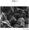
- many fine recessed and projected parts are formed on the surface of the steel sheet. These fine recessed and projected parts increase the contact area between the separator (stainless steel sheet) and the gas diffusion layer. This results in a decrease in contact resistance.
- recessed parts and sharp-tipped projected parts are formed on the surface of the stainless steel sheet of this disclosure. Therefore, as illustrated in FIG.
- [chemical form other than metal (Cr + Fe)] / [metal form (Cr + Fe)] is the ratio of the total Cr and Fe present in the chemical form other than metal to the total Cr and Fe present in the metal form on the steel sheet surface.
- [metal form (Cr + Fe)] is a total atomic concentration of Cr and Fe present in the metal form
- [chemical form other than metal (Cr + Fe)] is a total atomic concentration of Cr and Fe present in the chemical form other than metal, which are measured when analyzing the steel sheet surface by X-ray photoelectron spectroscopy.
- recessed parts and sharp-tipped projected parts are formed on the surface of the stainless steel sheet of this disclosure. Therefore, when the separator (stainless steel sheet) contacts the gas diffusion layer, the tips of the projected parts formed on the surface of the stainless steel sheet of this disclosure pierce the carbon fiber of the gas diffusion layer. Then, these parts (where the tips of the projected parts pierce the carbon fiber of the gas diffusion layer) become current paths to decrease the contact resistance. However, during etching by the first immersion treatment, a large amount of smut (a mixture of C, N, S, O, Fe, Cr, Ni, and Cu as major constituent elements) is generated and adheres to the steel sheet surface, as the steel sheet is dissolved.
- smut a mixture of C, N, S, O, Fe, Cr, Ni, and Cu as major constituent elements
- the steel sheet as subjected to the first immersion treatment incurs an increase in contact resistance due to the effect of such smut.
- the second immersion treatment performing (B) or (C) above, i.e., using an aqueous solution containing nitric acid as the treatment solution, makes it possible to particularly effectively remove the smut adhered to the steel sheet surface.
- the amount of smut on the steel sheet surface is correlated with [chemical form other than metal (Cr + Fe)] / [metal form (Cr + Fe)].
- a lower [chemical form other than metal (Cr + Fe)] / [metal form (Cr + Fe)] means that the smut is sufficiently removed. Therefore, controlling [chemical form other than metal (Cr + Fe)] / [metal form (Cr + Fe)] to 8.0 or less further reduces the contact resistance.
- the average grain size of the stainless steel sheet is preferably 10 ⁇ m or more and that the average grain size of the stainless steel sheet is preferably 40 ⁇ m or less.
- the following describes a stainless steel sheet for fuel cell separators according to one of the disclosed embodiments.
- it is important to form a textured structure having recessed parts and projected parts on the surface to control the textured shape.
- Parameter Sa specified in ISO 25178 0.15 ⁇ m or more and 0.50 ⁇ m or less
- Sa is one of surface roughness parameters specified in ISO 25178 and represents an arithmetic mean height.
- the arithmetic mean height is the mean of the absolute values of difference in height of respective points relative to the mean plane of the surface and is a parameter commonly used in evaluating surface roughness.
- Sa is 0.15 ⁇ m or more.
- Sa is preferably 0.20 ⁇ m or more.
- Sa is 0.50 ⁇ m or less.
- Sa is preferably 0.48 ⁇ m or less, more preferably 0.45 ⁇ m or less, and further preferably 0.40 ⁇ m or less.
- a parameter Ssk (skewness) specified in ISO 25178 is one of surface roughness parameters and represents the symmetry of height distribution. As illustrated in FIG. 2 , a positive value (more than 0) for Ssk (skewness) indicates that the tips (upper ends) of the projected parts (mountains) are sharp and the tips (lower ends) of the recessed parts (valleys) are wide (close to flat). On the other hand, a negative value (less than 0) for Ssk indicates that the tips (upper ends) of the projected parts (mountains) are wide (close to flat) and the tips (lower ends) of the recessed parts (valleys) are sharp.
- Ssk is more than 0.
- Ssk is preferably 0.10 or more. No particular upper limit is placed on Ssk.
- Ssk is preferably 1.0 or less because an excessive increase in Ssk may result in a decrease in the number of projected parts, which in turn increases the contact resistance.
- Sa and Ssk may be measured in accordance with ISO 25178. For example, a laser microscope may be used as a measurement device.
- Sa may be 0.15 ⁇ m or more and 0.50 ⁇ m or less, and Ssk may be more than 0, on at least one surface (surface on the side in contact with the gas diffusion layer).
- Sa is 0.15 ⁇ m or more and 0.50 ⁇ m or less, and Ssk is more than 0, on both sides.
- [chemical form other than metal (Cr + Fe)] / [metal form (Cr + Fe)] can further enhance the contact resistance reduction effect in a fuel cell separator use environment. Therefore, [chemical form other than metal (Cr + Fe)] / [metal form (Cr + Fe)] is preferably 8.0 or less. [chemical form other than metal (Cr + Fe)] / [metal form (Cr + Fe)] is preferably 7.0 or less, more preferably 6.0 or less, and further preferably 5.0 or less.
- [chemical form other than metal (Cr + Fe)] / [metal form (Cr + Fe)] is more than 8.0, smut removal on the steel sheet surface is not sufficient and further contact resistance reduction effect is not obtained. No particular lower limit is placed on [chemical form other than metal (Cr + Fe)] / [metal form (Cr + Fe)].
- [chemical form other than metal (Cr + Fe)] / [metal form (Cr + Fe)] is preferably 2.0 or more because an excessive reduction increases the treatment time.
- the chemical form other than metal denotes oxide and hydroxide.
- Cr includes CrO 2 , Cr 2 O 3 , CrOOH, Cr(OH) 3 , and CrO 3 .
- Fe includes FeO, Fe 3 O 4 , Fe 2 O 3 , and FeOOH.
- the steel sheet surface is measured by X-ray photoelectron spectroscopy (hereinafter, also referred to as XPS), and the obtained Cr peaks are separated into peaks of Cr present in the metal form and peaks of Cr present in the chemical form other than metal.
- the obtained Fe peaks are separated into peaks of Fe present in the metal form and peaks of Fe present in the chemical form other than metal.
- the sum of the atomic concentrations of Cr present in the chemical form other than metal and Fe present in the chemical form other than metal which is calculated from the above, is divided by the sum of the atomic concentrations of Cr present in the metal form and Fe present in the metal form to determine [chemical form other than metal (Cr + Fe)] / [metal form (Cr + Fe)].
- a 10 mm square sample is cut from the steel sheet, and the sample is measured with an X-ray photoelectron spectrometer (X-tool made by ULVAC-PHI) using an Al-K ⁇ monochrome X-ray source at an extraction angle of 45 degrees. Then, the Cr and Fe peaks obtained from the measurement are separated into peaks present in the metal form and peaks present in the chemical form other than metal each for Cr and Fe.
- X-tool made by ULVAC-PHI
- the sum of the atomic concentrations of Cr present in the chemical form other than metal and Fe present in the chemical form other than metal is divided by the sum of the atomic concentrations of Cr present in the metal form and Fe present in the metal form to determine [chemical form other than metal (Cr + Fe)] / [metal form (Cr + Fe).
- the peak separation is performed by removing the background of the spectrum by Shirley method and using a Gauss-Lorentz complex function (proportion of Lorentz function: 30 %).
- the average grain size is preferably 10 ⁇ m or more, and the average grain size is preferably 40 ⁇ m or less.
- Average grain size 10 ⁇ m or more and 40 ⁇ m or less
- a stainless steel sheet as rolled that has not been annealed has a uniform, non-recrystallized deformed microstructure.
- a stainless steel sheet as rolled is subjected to a first immersion treatment described below, dissolution uniformly progresses in the stainless steel sheet.
- the boundaries of respective recrystallized crystal grains are the initiation points for dissolution. Therefore, when such an annealed stainless steel sheet is subjected to the first immersion treatment described below, dissolution non-uniformly progresses in the stainless steel sheet.
- the desired surface characteristics (Sa and Ssk) of the stainless steel sheet is obtained with a smaller amount of dissolution by appropriately controlling the size of the crystal grains in the stainless steel sheet, specifically, by controlling the average grain size to the range of 10 ⁇ m or more and 40 ⁇ m or less. If the amount of dissolution can be reduced, many advantages can be obtained, such as shorter treatment time (immersion time) in the first immersion treatment, lower treatment temperature, lower treatment liquid consumption, and lower cost of disposing used treatment liquid, as well as higher product yield rate.
- the average grain size of the stainless steel foil is preferably 10 ⁇ m or more, and the average grain size of the stainless steel foil is preferably 40 ⁇ m or less.
- the average grain size of the stainless steel sheet is determined by electron backscatter diffraction (EBSD) analysis.
- the stainless steel sheet is embedded in resin and its surface is polished so that the cross section parallel to the rolling direction of the stainless steel sheet is exposed. Then, the EBSD analysis is performed to calculate the average grain size based on the Area Fraction method.
- the field of view area for performing the EBSD analysis is desirably 0.025 mm 2 or more.
- the width of the field of view is desirably 0.25 mm or more.
- Other conditions may be in accordance with conventional methods.
- the grain size of each crystal grain is determined by calculating the equivalent circle diameter from the area of each crystal grain determined by the Area Fraction method.
- the stainless steel sheet for fuel cell separators is not particularly limited, but preferably has a chemical composition (hereinafter, also referred to as a "preferred chemical composition”) containing, by mass%, C: 0.100 % or less, Si: 2.00 % or less, Mn: 3.00 % or less, P: 0.050 % or less, S: 0.010 % or less, Cr: 15.0 % or more and 25.0 % or less, Ni: 0.01 % or more and 30.0 % or less, Al: 0.500 % or less, and N: 0.100 % or less, and optionally containing one or two or more selected from:
- a lower C content is preferable, and the C content is preferably 0.100 % or less.
- the C content is more preferably 0.060 % or less. No particular lower limit is placed on the C content. However, the lower limit is preferably 0.001 %.
- Si is an element useful for deoxidization and added at a step of smelting steel.
- the effect is preferably obtained through a Si content of 0.01 % or more.
- an excessive Si content hardens the steel and tends to decrease ductility. Therefore, the Si content is preferably 2.00 % or less.
- the Si content is more preferably 1.00 % or less.
- Mn is an element useful for deoxidation and added at a step of smelting steel.
- the effect is preferably obtained through a Mn content of 0.01 % or more. If the Mn content is more than 3.00 %, however, the corrosion resistance tends to decrease. Therefore, the Mn content is preferably 3.00 % or less.
- the Mn content is more preferably 1.50 % or less, and further preferably 1.00 % or less.
- the P content is desirably low. If the P content is 0.050 % or less, however, the ductility does not decrease markedly. Therefore, the P content is preferably 0.050 % or less. The P content is more preferably 0.040 % or less. No particular lower limit is placed on the P content. However, excessive dephosphorization incurs higher cost. Therefore, the P content is preferably 0.010 % or more.
- S is an element that combines with Mn to form MnS, decreasing corrosion resistance. If the S content is 0.010 % or less, however, the corrosion resistance does not decrease markedly. Therefore, the S content is preferably 0.010 % or less. No particular lower limit is placed on the S content. However, excessive desulfurization incurs higher cost. Therefore, the S content is preferably 0.001 % or more.
- the Cr content is preferably 15.0 % or more in order to ensure the corrosion resistance. That is, if the Cr content is less than 15.0 %, the stainless steel sheet has difficulty in withstanding long-term use as a fuel cell separator in terms of the corrosion resistance.
- the Cr content is more preferably 18.0 % or more.
- the Cr content is preferably 25.0 % or less.
- the Cr content is more preferably 23.0 % or less, and further preferably 21.0 % or less.
- Ni 0.01 % or more and 30.0 % or less
- Ni is an element useful for improving the corrosion resistance of stainless steel.
- Austenitic stainless steel or ferrite-austenite dual phase stainless steel generally contains a fixed amount of Ni. If the Ni content is more than 30.0 %, however, hot workability decreases. Therefore, the Ni content is preferably 30.0 % or less. The Ni content is more preferably 20.0 % or less. Further, the Ni content is preferably 0.01% or more.
- the lower limit of the Ni content in austenitic stainless steel or ferrite-austenite dual phase stainless steel is preferably 2.00 %.
- the Ni content is preferably 2.00 % or less, and more preferably 1.00 % or less.
- the lower limit of the Ni content in ferritic stainless steel is preferably 0.01 %.
- Al is an element used for deoxidation. The effect is preferably obtained through an Al content of 0.001 % or more. If the Al content is more than 0.500 %, however, the ductility may decrease. Therefore, the Al content is preferably 0.500 % or less. The Al content is more preferably 0.010 % or less, and further preferably 0.005 % or less.
- the N content is preferably 0.100 % or less.
- the N content is more preferably 0.050 % or less, and further preferably 0.030 % or less. No particular lower limit is placed on the N content. However, excessive denitrogenation incurs higher cost. Therefore, the N content is preferably 0.002 % or more.
- Cu is an element useful for promoting the formation of the austenite phase and improving the corrosion resistance of stainless steel.
- the effect is preferably obtained through a Cu content of 0.01 % or more. If the Cu content is more than 2.50 %, however, the hot workability decreases to incur a decrease in productivity. Therefore, when Cu is added, the Cu content is 2.50 % or less.
- the Cu content is preferably 1.00 % or less.
- Mo is an element useful for preventing local corrosion such as crevice corrosion of stainless steel.
- the effect is preferably obtained through a Mo content of 0.01 % or more. If the Mo content is more than 4.00 %, however, stainless steel embrittles. Therefore, when Mo is added, the Mo content is 4.00 % or less.
- the Mo content is preferably 2.50 % or less.
- Ti, Nb, and Zr contribute to improved intergranular corrosion resistance, and therefore these elements can be added alone or in combination.
- the effect is preferably obtained through a content of each element of 0.01 % or more. If the total content of these elements is more than 1.00 %, however, the ductility tends to decrease. Therefore, when Ti, Nb, and Zr are added, the total content of these elements is 1.00 % or less. No particular lower limit is placed on the total content of Ti, Nb, and Zr. However, the total content of Ti, Nb, and Zr is preferably 0.01 % or more.
- the components other than those described above are Fe and inevitable impurities.
- the stainless steel sheet for fuel cell separators may be any one of a ferritic stainless steel sheet, an austenitic stainless steel sheet, and a ferrite-austenitic dual phase stainless steel sheet.
- the austenitic stainless steel sheet is preferable.
- the microstructure of the ferritic stainless steel sheet may be a single-phase microstructure of a ferrite phase, or it may contain precipitates with a volume fraction of 1 % or less as the balance other than the ferrite phase.
- the microstructure of the austenitic stainless steel sheet may be a single-phase microstructure of an austenite phase, or it may contain precipitates with a volume fraction of 1 % or less as the balance other than the austenite phase.
- the microstructure of the ferrite-austenite dual phase stainless steel sheet may consist of a ferrite phase and an austenite phase, or it may contain precipitates with a volume fraction of 1 % or less as the balance other than the ferrite phase and the austenite phase.
- the above precipitates include, for example, one or two or more selected from the group consisting of intermetallic compounds, carbides, nitrides, and sulfides.
- the identification of each phase may be performed in accordance with conventional methods.
- the thickness of the stainless steel sheet for fuel cell separators according to one of the embodiments is preferably in the range of 0.03 mm to 0.30 mm. If the sheet thickness is less than 0.03 mm, the production efficiency of a metal sheet material decreases. On the other hand, if the sheet thickness is more than 0.30 mm, the installation space and weight when stacking fuel cells increase.
- the thickness of the stainless steel sheet for fuel cell separators according to one of the embodiments is more preferably 0.05 mm or more. Further, the thickness of the stainless steel sheet for fuel cell separators according to one of the embodiments is more preferably 0.15 mm or less.
- the following describes a method of producing a stainless steel sheet for fuel cell separators according to one of the embodiments.
- the preparation process is a process to prepare a stainless steel sheet to be used as a material (hereinafter, also referred to as a "material stainless steel sheet").
- the method of preparing the material stainless steel sheet is not particularly limited.
- a material stainless steel sheet having the above chemical composition may be prepared as follows.
- the material stainless steel sheet having the above chemical composition can be prepared by hot rolling a steel slab having the above chemical composition to obtain a hot-rolled sheet, optionally subjecting the hot-rolled sheet to hot-rolled sheet annealing and acid cleaning, thereafter, cold rolling the hot-rolled sheet to obtain a cold-rolled sheet with a desired sheet thickness, and further optionally subjecting the cold-rolled sheet to cold-rolled sheet annealing.
- Conditions for hot rolling, cold rolling, hot-rolled sheet annealing, cold-rolled sheet annealing, and the like are not particularly limited, and may be in accordance with conventional methods. After cold-rolled sheet annealing, the cold-rolled sheet may be subjected to acid cleaning and skin pass. Cold-rolled sheet annealing can also be bright annealing.
- finish annealing which is the final annealing in cold-rolled sheet annealing, in particular, the finish annealing temperature and the finish annealing time.
- finish annealing temperature in the range of 1050 °C to 1250 °C and the finish annealing time in the range of 20 seconds to 90 seconds.
- the finish annealing temperature in the range of 750 °C to 1050 °C and the finish annealing time in the range of 20 seconds to 90 seconds.
- the material stainless steel sheet prepared as described above is subjected to immersion treatment (etching treatment) using an acidic aqueous solution containing: hydrogen peroxide of 0.1 mass% or more and 5.0 mass% or less, copper ion of 1.0 mass% or more and 10.0 mass% or less, and halide ion of 5.0 mass% or more and 20.0 mass% or less, with pH of 1.0 or less, as a treatment solution, with a treatment temperature of 30 °C or more and 50 °C or less and a treatment time of 40 seconds or more and 120 seconds or less, respectively.
- etching treatment an acidic aqueous solution containing: hydrogen peroxide of 0.1 mass% or more and 5.0 mass% or less, copper ion of 1.0 mass% or more and 10.0 mass% or less, and halide ion of 5.0 mass% or more and 20.0 mass% or less, with pH of 1.0 or less, as a treatment solution, with a treatment temperature of 30 °C or more and 50 °C or less
- Applying the etching treatment according to the above conditions enables to precisely control the amount of dissolution of the stainless steel sheet and, in turn, the shape of the textured structure formed on the steel sheet surface as described above.
- the following describes the etching treatment conditions.
- the amount of dissolution of the stainless steel sheet during the etching treatment varies depending on the type and temperature of the treatment solution used in the etching treatment, as well as the treatment time. Thus, it is important to appropriately control these conditions to achieve the desired surface characteristics (For example, because there are parts that are likely to dissolve and parts that are unlikely to dissolve on the steel sheet surface, the etching treatment forms recessed parts and projected parts on the steel sheet surface.
- Hydrogen peroxide 0.1 mass% or more and 5.0 mass% or less
- the concentration of hydrogen peroxide is less than 0.1 mass%, the power to remove copper-containing products precipitated on the steel sheet surface is reduced, making continuous etching treatment impossible.
- the concentration of hydrogen peroxide is more than 5.0 mass%, the effect is saturated. Therefore, the concentration of hydrogen peroxide is preferably 0.1 mass% or more, and the concentration of hydrogen peroxide is preferably 5.0 mass% or less.
- Copper ion 1.0 mass% or more and 10.0 mass% or less
- the concentration of copper ions is less than 1.0 mass%, the etching power is reduced, making it impossible to form the predetermined textured structure shape on the steel sheet surface.
- the concentration of copper ions is more than 10.0 mass%, more products adhere to the steel sheet surface, making it impossible to sufficiently remove the smut even with the second immersion treatment in the next process. Therefore, the concentration of copper ions is preferably 1.0 mass% or more, and the concentration of copper ions is preferably 10.0 mass% or less.
- the concentration of copper ions is preferably 2.0 mass% or more, and further preferably 5.0 mass% or more.
- Halide ion 5.0 mass% or more and 20.0 mass% or less
- the concentration of halide ions is preferably 5.0 mass% or more, and the concentration of halide ions is preferably 20.0 mass% or less.
- the concentration of halide ions is preferably 10.0 mass% or more. Further, the concentration of halide ions is preferably 15.0 mass% or less.
- the type of halide ion source is not particularly limited. However, for example, hydrogen halides or alkali metal halides are preferable, and hydrochloric acid or sodium chloride is more preferable.
- the pH of the treatment solution is 1.0 or less.
- the pH of the treatment solution is desirably lower, and more preferably 0.1 or less.
- the above aqueous solution can be prepared by uniformly stirring a hydrogen peroxide aqueous solution, a copper compound capable of supplying copper ions, a halide component capable of supplying halide ions, and water.
- Treatment temperature (temperature of treatment solution): 30 °C or more and 50 °C or less
- the treatment temperature is less than 30 °C, the etching force is reduced to incur an increase in treatment time.
- the treatment temperature is more than 50 °C, the stability of the treatment solution decreases. Therefore, the treatment temperature is 30 °C or more and 50 °C or less.
- Treatment time 40 seconds or more and 120 seconds or less
- the treatment time is less than 40 seconds, a sufficient amount of etching cannot be obtained.
- the treatment time is more than 120 seconds, making it impossible to form the predetermined textured structure shape on the steel sheet surface. This also reduces the productivity. Therefore, the treatment time is 40 seconds or more and 120 seconds or less.
- the amount of etching varies depending on the type of stainless steel. Thus, it is more preferable to adjust the treatment time within the range of 40 seconds to 120 seconds, depending on the type of steel.
- Conditions other than the above are not particularly limited and may be in accordance with conventional methods.
- the above describes the treatment in which the material stainless steel sheet is immersed in the aqueous solution, a treatment solution.
- the above aqueous solution to be a treatment solution can be, for example, dropped or sprayed.
- the treatment time is the contact time between the material stainless steel sheet and the aqueous solution.
- the material stainless steel sheet is further subjected to:
- the acidic aqueous solution containing hydrogen peroxide is a mixed aqueous solution of hydrogen peroxide and sulfuric acid.
- the solution containing nitric acid is a nitric acid aqueous solution.
- the concentration of hydrogen peroxide is preferably 0.5 mass% or more and the concentration of sulfuric acid is preferably 1.0 mass% or more, and the concentration of hydrogen peroxide is preferably 10.0 mass% or less and the concentration of sulfuric acid is preferably 10.0 mass% or less.
- the concentration of nitric acid is preferably 1.0 mass% or more, and the concentration of nitric acid is preferably 40.0 mass% or less.
- the component other than hydrogen peroxide and sulfuric acid in the mixed aqueous solution of hydrogen peroxide and sulfuric acid, and the component other than nitric acid in the nitric acid aqueous solution, are basically water.
- the treatment temperature (temperature of the treatment solution) in the second immersion treatment is preferably 30 °C or more and the treatment temperature (temperature of the treatment solution) in the second immersion treatment is preferably 60 °C or less, in any cases of (A) to (C) above.
- the treatment time is preferably 5 seconds or more and the treatment time is preferably 120 seconds or less, in any cases of (A) to (C) above.
- the treatment time is more preferably 30 seconds or more.
- the treatment time is more preferably 90 seconds or less.
- performing the immersion treatment using an aqueous solution containing nitric acid can more effectively dissolve (remove) the smut formed during the first immersion treatment (etching treatment), thereby further enhancing the contact resistance reduction effect.
- the second immersion treatment if necessary, scrubbing the surface of the stainless steel sheet as a treated material with a non-woven fabric wiper or the like facilitates the removal of smut, which will stably obtain further contact resistance reduction effect.
- the above describes the treatment in which the material stainless steel sheet is immersed in the aqueous solution, a treatment solution.
- the above aqueous solution to be a treatment solution can be, for example, dropped or sprayed.
- the treatment time is the contact time between the material stainless steel sheet and the aqueous solution.
- the second immersion treatment may be applied after the stainless steel sheet is processed into a separator shape.
- a surface-coating layer may be further formed on the steel sheet surface.
- the surface-coating layer to be formed is not particularly limited. However, it is preferable to use a material that has excellent corrosion resistance and conductivity in the fuel cell separator use environment. For example, it is preferable to use a metal layer, an alloy layer, a metal oxide layer, a metal carbide layer, a metal nitride layer, a carbon material layer, a conductive polymer layer, an organic resin layer containing a conductive substance, or a mixed layer thereof.
- metal layer examples include metal layers of Au, Ag, Cu, Pt, Pd, W, Sn, Ti, Al, Zr, Nb, Ta, Ru, Ir, and Ni.
- a metal layer of Au or Pt is particularly preferable.
- the alloy layer examples include Sn alloy layers of Ni-Sn (Ni 3 Sn 2 , Ni 3 Sn 4 ), Cu-Sn (CusSn, Cu 6 Sn 5 ), Fe-Sn (FeSn, FeSn 2 ), Sn-Ag, and Sn-Co, and alloy layers of Ni-W, Ni-Cr, and Ti-Ta.
- An alloy layer of Ni-Sn or Fe-Sn is particularly preferable.
- the metal oxide layer examples include metal oxide layers of SnO 2 , ZrO 2 , TiO 2 , WO 3 , SiO 2 , Al 2 O 3 , Nb 2 O 5 , IrO 2 , RuO 2 , PdO 2 , Ta 2 O 5 , Mo 2 O 5 , and Cr 2 O 3 .
- a metal oxide layer of TiO 2 or SnO 2 is particularly preferable.
- metal nitride layer and the metal carbide layer examples include metal nitride layers and metal carbide layers of TiN, CrN, TiCN, TiAlN, AlCrN, TiC, WC, SiC, B 4 C, molybdenum nitride, CrC, TaC, and ZrN.
- a metal nitride layer of TiN is particularly preferable.
- Examples of the carbon material layer include carbon material layers of graphite, amorphous carbon, diamond-like carbon, carbon black, fullerene, and carbon nanotube.
- a carbon material layer of graphite or diamond-like carbon is particularly preferable.
- Examples of the conductive polymer layer include conductive polymer layers of polyaniline and polypyrrole.
- the organic resin layer containing a conductive substance contains at least one of conductive substances selected from metals, alloys, metal oxides, metal nitrides, metal carbides, carbon materials, or conductive polymers that constitute the above metal layer, alloy layer, metal oxide layer, metal nitride layer, metal carbide layer, carbon material layer, and conductive polymer layer, and contains at least one of organic resins selected from an epoxy resin, a phenol resin, a polyamide-imide resin, a polyester resin, a polyphenylene sulfide resin, a polyamide resin, a urethane resin, an acrylic resin, a polyethylene resin, a polypropylene resin, a carbodiimide resin, or a phenol epoxy resin.
- a graphite-dispersed phenol resin or a carbon black-dispersed epoxy resin is preferable.
- a metal and a carbon material are preferable.
- the content of the conductive substance is not particularly limited, as long as predetermined conductivity is obtained in a separator for polymer electrolyte fuel cells.
- Examples of the above mixed layer include a mixed layer of a TiN-dispersed Ni-Sn alloy.
- the above treatment may be performed after the stainless steel sheet is processed into a separator shape.
- Material stainless steel sheets obtained by bright annealing after cold rolling
- a thickness of 0.10 mm having the chemical compositions of Steel No. A to G presented in Table 1 (the balance being Fe and inevitable impurities) were prepared.
- the prepared stainless steel sheets were then subjected to the first immersion treatment (etching treatment) and the second immersion treatment (smut removal treatment) under the conditions presented in Tables 2 and 3 to obtain stainless steel sheets for fuel cell separators.
- the stainless steel sheets were immersed in pure water to stop the reaction.
- the copper ion and the chloride ion are derived from copper sulfate pentahydrate and hydrochloric acid, respectively.
- the copper ion and the chloride ion are derived from copper sulfate pentahydrate and hydrochloric acid, respectively.
- the copper ion and the chloride ion are derived from copper sulfate pentahydrate and hydrochloric acid, respectively.
- the copper ion and the chloride ion are derived from copper sulfate pentahydrate and hydrochloric acid, respectively.
- the thus obtained stainless steel sheets for fuel cell separators were measured for Sa and Ssk in accordance with ISO 25178.
- a laser microscope VK-X250/X260 made by Keyence
- a test specimen was taken from each of the stainless steel sheets for fuel cell separators, and the surface profile data of a 50 ⁇ m ⁇ 50 ⁇ m area on each side of the test specimen was measured with the above laser microscope using an objective lens with a magnification of 150 ⁇ .
- the obtained data was analyzed using analysis software "Multi-file Analysis Application" provided with the device to obtain Sa and Ssk on each side of the test specimen.
- the image was processed by removing and interpolating areas where the light intensity was outside the threshold range (0.00 to 99.5), smoothing with a Gaussian function and setting a cut level to remove noise and the like. Then, a plane was set as the reference plane for measurement by reference plane setting, and the curved surface was corrected to a plane by quadratic surface correction.
- the filter type was Gaussian, and the cutoff wavelength specified by the S-filter was 0.5 ⁇ m.
- the measurement results are presented in Tables 2 and 3.
- the values of Sa and Ssk were almost the same on both sides for any test specimens. Thus, the values of Sa and Ssk measured on one side of the test specimen are representatively presented in Tables 2 and 3. For reference, the steel sheet of Steel No.
- the first immersion treatment etching treatment
- the second immersion treatment smut removal treatment
- the thickness of each of the thus obtained stainless steel sheets for fuel cell separators was measured with a micrometer.
- the thickness reduction quantity due to the immersion treatment was then calculated by subtracting the thickness of the stainless steel sheet for fuel cell separators measured after the immersion treatment from the thickness of the material stainless steel sheet measured before the immersion treatment.
- Sa and Ssk were also measured in the same manner as in Example 1.
- the average grain size was measured in the above manner. The measurement results are presented in Table 4. "Unmeasurable" in the column of Average grain size in Table 4 means that no crystal grain boundaries were observed in the electron backscatter diffraction (EBSD) analysis and the average grain size could not be measured.
- EBSD electron backscatter diffraction
- Example 2 The same manner as in Example 1 was used to calculate [chemical form other than metal (Cr + Fe)] / [metal form (Cr + Fe)]. The results are presented in Table 4.
- Each chemical composition of the finally obtained stainless steel sheets for fuel cell separators was substantially the same as the chemical composition of each Steel No. presented in Table 1, and each satisfied the above range of preferred chemical compositions.
Landscapes
- Chemical & Material Sciences (AREA)
- Engineering & Computer Science (AREA)
- Materials Engineering (AREA)
- Mechanical Engineering (AREA)
- Metallurgy (AREA)
- Organic Chemistry (AREA)
- Chemical Kinetics & Catalysis (AREA)
- General Chemical & Material Sciences (AREA)
- Life Sciences & Earth Sciences (AREA)
- Sustainable Energy (AREA)
- Sustainable Development (AREA)
- Electrochemistry (AREA)
- Manufacturing & Machinery (AREA)
- Fuel Cell (AREA)
Applications Claiming Priority (2)
| Application Number | Priority Date | Filing Date | Title |
|---|---|---|---|
| JP2020207212 | 2020-12-15 | ||
| PCT/JP2021/045803 WO2022131204A1 (fr) | 2020-12-15 | 2021-12-13 | Tôle d'acier inoxydable pour séparateur de pile à combustible |
Publications (2)
| Publication Number | Publication Date |
|---|---|
| EP4265761A1 true EP4265761A1 (fr) | 2023-10-25 |
| EP4265761A4 EP4265761A4 (fr) | 2024-05-29 |
Family
ID=82059178
Family Applications (1)
| Application Number | Title | Priority Date | Filing Date |
|---|---|---|---|
| EP21906566.1A Pending EP4265761A4 (fr) | 2020-12-15 | 2021-12-13 | Tôle d'acier inoxydable pour séparateur de pile à combustible |
Country Status (6)
| Country | Link |
|---|---|
| US (1) | US20240006621A1 (fr) |
| EP (1) | EP4265761A4 (fr) |
| JP (1) | JP7226648B2 (fr) |
| KR (1) | KR102880076B1 (fr) |
| CN (1) | CN116635551A (fr) |
| WO (1) | WO2022131204A1 (fr) |
Cited By (1)
| Publication number | Priority date | Publication date | Assignee | Title |
|---|---|---|---|---|
| EP4245877A4 (fr) * | 2020-12-15 | 2024-04-17 | JFE Steel Corporation | Tôle d'acier contenant du chrome pour collecteurs de courant pour batteries rechargeables à électrolyte non aqueux |
Families Citing this family (1)
| Publication number | Priority date | Publication date | Assignee | Title |
|---|---|---|---|---|
| KR20240098332A (ko) * | 2022-12-21 | 2024-06-28 | 주식회사 포스코 | 오스테나이트계 스테인리스강 및 이의 제조방법 |
Family Cites Families (21)
| Publication number | Priority date | Publication date | Assignee | Title |
|---|---|---|---|---|
| JPS5819950B2 (ja) * | 1980-11-06 | 1983-04-20 | 新日本製鐵株式会社 | 太陽熱選択吸収板の製造法 |
| JP3460346B2 (ja) | 1994-12-26 | 2003-10-27 | 富士電機株式会社 | 固体高分子電解質型燃料電池 |
| KR100259299B1 (en) * | 1998-04-21 | 2000-06-15 | Lg Electronics Inc | Shadow mask of color cathode ray tube and method for fabricating the same |
| JP4629914B2 (ja) | 2001-06-04 | 2011-02-09 | 日新製鋼株式会社 | 低温型燃料電池用セパレータ及びその製造方法 |
| JP4173376B2 (ja) * | 2003-01-14 | 2008-10-29 | 新日鉄マテリアルズ株式会社 | 拡散接合性の良好な排気ガス浄化用メタル担体用耐熱ステンレス鋼箔およびメタル担体 |
| JP2005089800A (ja) * | 2003-09-16 | 2005-04-07 | Jfe Steel Kk | 固体高分子型燃料電池セパレータ用ステンレス鋼およびそれを用いた固体高分子型燃料電池 |
| JP5109234B2 (ja) * | 2004-03-18 | 2012-12-26 | Jfeスチール株式会社 | 固体高分子型燃料電池セパレータ用金属材料,それを用いた燃料電池用セパレータ,その燃料電池および固体高分子型燃料電池セパレータ用金属材料の表面粗さ調整処理方法 |
| KR100993412B1 (ko) * | 2008-12-29 | 2010-11-09 | 주식회사 포스코 | 고분자 연료전지 분리판용 스테인리스강 및 그 제조방법 |
| JP2011038166A (ja) * | 2009-08-13 | 2011-02-24 | Nisshin Steel Co Ltd | 燃料電池用通電部材およびその製造方法 |
| JP5768641B2 (ja) | 2010-10-08 | 2015-08-26 | Jfeスチール株式会社 | 耐食性および電気伝導性に優れたフェライト系ステンレス鋼およびその製造方法、ならびに固体高分子型燃料電池セパレータおよび固体高分子型燃料電池 |
| JP6144006B2 (ja) | 2011-01-17 | 2017-06-07 | Jfeスチール株式会社 | 燃料電池セパレータ用ステンレス鋼の製造方法、燃料電池セパレータ用ステンレス鋼、燃料電池セパレータ、ならびに燃料電池 |
| JP5218612B2 (ja) | 2011-07-29 | 2013-06-26 | Jfeスチール株式会社 | 燃料電池セパレータ用ステンレス鋼 |
| EP2770567B1 (fr) | 2011-11-30 | 2016-09-21 | JFE Steel Corporation | Acier inoxydable destiné à des séparateurs de pile à combustible |
| JP5850185B2 (ja) * | 2013-02-01 | 2016-02-03 | 新日鐵住金株式会社 | 対カーボン接触導電性と耐久性に優れた燃料電池セパレータ用チタン材又はチタン合金材、これを用いた燃料電池セパレータ、及び、燃料電池 |
| WO2017212656A1 (fr) * | 2016-06-10 | 2017-12-14 | Jfeスチール株式会社 | Tôle d'acier inoxydable pour séparateurs de pile à combustible, et son procédé de production |
| KR102404291B1 (ko) * | 2017-04-25 | 2022-05-31 | 제이에프이 스틸 가부시키가이샤 | 연료 전지의 세퍼레이터용의 스테인리스 강판 및 그 제조 방법 |
| JP6937635B2 (ja) * | 2017-08-14 | 2021-09-22 | 日鉄ステンレス株式会社 | 発色用ステンレス鋼板とその製造方法 |
| KR102391553B1 (ko) | 2017-10-25 | 2022-04-27 | 제이에프이 스틸 가부시키가이샤 | 연료 전지의 세퍼레이터용 스테인리스 강판의 제조 방법 |
| KR102752484B1 (ko) * | 2019-01-21 | 2025-01-09 | 제이에프이 스틸 가부시키가이샤 | 연료 전지의 세퍼레이터용의 오스테나이트계 스테인리스 강판 |
| JP7281929B2 (ja) * | 2019-03-19 | 2023-05-26 | 日鉄ステンレス株式会社 | ステンレス鋼板およびステンレス鋼板の製造方法 |
| US20240063399A1 (en) * | 2020-12-15 | 2024-02-22 | Jfe Steel Corporation | Chromium-containing steel sheet for current collector of nonaqueous electrolyte secondary battery |
-
2021
- 2021-12-13 EP EP21906566.1A patent/EP4265761A4/fr active Pending
- 2021-12-13 US US18/255,740 patent/US20240006621A1/en active Pending
- 2021-12-13 KR KR1020237023845A patent/KR102880076B1/ko active Active
- 2021-12-13 WO PCT/JP2021/045803 patent/WO2022131204A1/fr not_active Ceased
- 2021-12-13 JP JP2022511392A patent/JP7226648B2/ja active Active
- 2021-12-13 CN CN202180084000.2A patent/CN116635551A/zh active Pending
Cited By (1)
| Publication number | Priority date | Publication date | Assignee | Title |
|---|---|---|---|---|
| EP4245877A4 (fr) * | 2020-12-15 | 2024-04-17 | JFE Steel Corporation | Tôle d'acier contenant du chrome pour collecteurs de courant pour batteries rechargeables à électrolyte non aqueux |
Also Published As
| Publication number | Publication date |
|---|---|
| JP7226648B2 (ja) | 2023-02-21 |
| CN116635551A (zh) | 2023-08-22 |
| WO2022131204A1 (fr) | 2022-06-23 |
| EP4265761A4 (fr) | 2024-05-29 |
| KR20230118962A (ko) | 2023-08-14 |
| US20240006621A1 (en) | 2024-01-04 |
| JPWO2022131204A1 (fr) | 2022-06-23 |
| KR102880076B1 (ko) | 2025-10-31 |
Similar Documents
| Publication | Publication Date | Title |
|---|---|---|
| JP6763501B1 (ja) | 燃料電池のセパレータ用のオーステナイト系ステンレス鋼板およびその製造方法 | |
| EP2458038B1 (fr) | Acier inoxydable pour pile à combustible présentant une excellente résistance à la corrosion et son procédé de production | |
| KR102315735B1 (ko) | 연료 전지의 세퍼레이터용의 스테인리스 강판 및 그 제조 방법 | |
| EP1046723B1 (fr) | Plaque bipolaire pour la production de pile à combustible avec les electrodes polymères | |
| TWI474539B (zh) | 燃料電池隔板用不鏽鋼 | |
| CN111263996B (zh) | 燃料电池的隔板用不锈钢板的制造方法 | |
| EP2460900A1 (fr) | Acier inoxydable pour des séparateurs de pile à combustible qui présente une excellente conductivité et une excellente ductilité et son procédé de fabrication | |
| JPWO2015111653A1 (ja) | 表面の導電性を有するチタン材又はチタン合金材とその製造方法、及び、これを用いた燃料電池セパレータと燃料電池 | |
| EP3998362A1 (fr) | Tôle d'acier inoxydable ferritique pour collecteurs de courant pour batteries à électrolyte solide à base de sulfure, et son procédé de fabrication | |
| JP6414369B1 (ja) | 燃料電池のセパレータ用鋼板の基材ステンレス鋼板およびその製造方法 | |
| JP5192908B2 (ja) | 燃料電池セパレータ用チタン基材、および、燃料電池セパレータ、ならびに燃料電池セパレータの製造方法 | |
| EP4265761A1 (fr) | Tôle d'acier inoxydable pour séparateur de pile à combustible | |
| Mori et al. | Effect of surface composition on contact resistivity and corrosion resistance of 316L stainless steel | |
| JP7608395B2 (ja) | 燃料電池のセパレータ用のステンレス鋼板の製造方法 | |
| JP2020024883A (ja) | 燃料電池のセパレータ用鋼板の基材ステンレス鋼板およびその製造方法 |
Legal Events
| Date | Code | Title | Description |
|---|---|---|---|
| STAA | Information on the status of an ep patent application or granted ep patent |
Free format text: STATUS: THE INTERNATIONAL PUBLICATION HAS BEEN MADE |
|
| PUAI | Public reference made under article 153(3) epc to a published international application that has entered the european phase |
Free format text: ORIGINAL CODE: 0009012 |
|
| STAA | Information on the status of an ep patent application or granted ep patent |
Free format text: STATUS: REQUEST FOR EXAMINATION WAS MADE |
|
| 17P | Request for examination filed |
Effective date: 20230707 |
|
| AK | Designated contracting states |
Kind code of ref document: A1 Designated state(s): AL AT BE BG CH CY CZ DE DK EE ES FI FR GB GR HR HU IE IS IT LI LT LU LV MC MK MT NL NO PL PT RO RS SE SI SK SM TR |
|
| DAV | Request for validation of the european patent (deleted) | ||
| DAX | Request for extension of the european patent (deleted) | ||
| A4 | Supplementary search report drawn up and despatched |
Effective date: 20240430 |
|
| RIC1 | Information provided on ipc code assigned before grant |
Ipc: C22C 38/50 20060101ALI20240426BHEP Ipc: C22C 38/48 20060101ALI20240426BHEP Ipc: C22C 38/44 20060101ALI20240426BHEP Ipc: C22C 38/42 20060101ALI20240426BHEP Ipc: C22C 38/06 20060101ALI20240426BHEP Ipc: C22C 38/04 20060101ALI20240426BHEP Ipc: C22C 38/02 20060101ALI20240426BHEP Ipc: C23F 1/28 20060101ALI20240426BHEP Ipc: C23F 1/16 20060101ALI20240426BHEP Ipc: H01M 8/10 20160101ALI20240426BHEP Ipc: H01M 8/021 20160101ALI20240426BHEP Ipc: C22C 38/58 20060101ALI20240426BHEP Ipc: C22C 38/00 20060101AFI20240426BHEP |