EP4265478B1 - Verbesserte modulare lichthalterungsgruppe und entsprechendes montageverfahren - Google Patents
Verbesserte modulare lichthalterungsgruppe und entsprechendes montageverfahren Download PDFInfo
- Publication number
- EP4265478B1 EP4265478B1 EP23162370.3A EP23162370A EP4265478B1 EP 4265478 B1 EP4265478 B1 EP 4265478B1 EP 23162370 A EP23162370 A EP 23162370A EP 4265478 B1 EP4265478 B1 EP 4265478B1
- Authority
- EP
- European Patent Office
- Prior art keywords
- bracket group
- light bracket
- central module
- module
- transverse
- Prior art date
- Legal status (The legal status is an assumption and is not a legal conclusion. Google has not performed a legal analysis and makes no representation as to the accuracy of the status listed.)
- Active
Links
Images






Classifications
-
- B—PERFORMING OPERATIONS; TRANSPORTING
- B60—VEHICLES IN GENERAL
- B60Q—ARRANGEMENT OF SIGNALLING OR LIGHTING DEVICES, THE MOUNTING OR SUPPORTING THEREOF OR CIRCUITS THEREFOR, FOR VEHICLES IN GENERAL
- B60Q1/00—Arrangement of optical signalling or lighting devices, the mounting or supporting thereof or circuits therefor
- B60Q1/26—Arrangement of optical signalling or lighting devices, the mounting or supporting thereof or circuits therefor the devices being primarily intended to indicate the vehicle, or parts thereof, or to give signals, to other traffic
- B60Q1/2619—Arrangement of optical signalling or lighting devices, the mounting or supporting thereof or circuits therefor the devices being primarily intended to indicate the vehicle, or parts thereof, or to give signals, to other traffic built in the vehicle body
- B60Q1/2649—Arrangement of optical signalling or lighting devices, the mounting or supporting thereof or circuits therefor the devices being primarily intended to indicate the vehicle, or parts thereof, or to give signals, to other traffic built in the vehicle body with provision for pre-mounting or temporary holding the device before or during final mounting
-
- B—PERFORMING OPERATIONS; TRANSPORTING
- B60—VEHICLES IN GENERAL
- B60Q—ARRANGEMENT OF SIGNALLING OR LIGHTING DEVICES, THE MOUNTING OR SUPPORTING THEREOF OR CIRCUITS THEREFOR, FOR VEHICLES IN GENERAL
- B60Q1/00—Arrangement of optical signalling or lighting devices, the mounting or supporting thereof or circuits therefor
- B60Q1/26—Arrangement of optical signalling or lighting devices, the mounting or supporting thereof or circuits therefor the devices being primarily intended to indicate the vehicle, or parts thereof, or to give signals, to other traffic
- B60Q1/30—Arrangement of optical signalling or lighting devices, the mounting or supporting thereof or circuits therefor the devices being primarily intended to indicate the vehicle, or parts thereof, or to give signals, to other traffic for indicating rear of vehicle, e.g. by means of reflecting surfaces
-
- B—PERFORMING OPERATIONS; TRANSPORTING
- B60—VEHICLES IN GENERAL
- B60Q—ARRANGEMENT OF SIGNALLING OR LIGHTING DEVICES, THE MOUNTING OR SUPPORTING THEREOF OR CIRCUITS THEREFOR, FOR VEHICLES IN GENERAL
- B60Q1/00—Arrangement of optical signalling or lighting devices, the mounting or supporting thereof or circuits therefor
- B60Q1/26—Arrangement of optical signalling or lighting devices, the mounting or supporting thereof or circuits therefor the devices being primarily intended to indicate the vehicle, or parts thereof, or to give signals, to other traffic
- B60Q1/30—Arrangement of optical signalling or lighting devices, the mounting or supporting thereof or circuits therefor the devices being primarily intended to indicate the vehicle, or parts thereof, or to give signals, to other traffic for indicating rear of vehicle, e.g. by means of reflecting surfaces
- B60Q1/305—Indicating devices for towed vehicles
-
- B—PERFORMING OPERATIONS; TRANSPORTING
- B60—VEHICLES IN GENERAL
- B60R—VEHICLES, VEHICLE FITTINGS, OR VEHICLE PARTS, NOT OTHERWISE PROVIDED FOR
- B60R13/00—Elements for body-finishing, identifying, or decorating; Arrangements or adaptations for advertising purposes
- B60R13/10—Registration, licensing, or like devices
- B60R13/105—Licence- or registration plates, provided with mounting means, e.g. frames, holders, retainers, brackets
-
- B—PERFORMING OPERATIONS; TRANSPORTING
- B60—VEHICLES IN GENERAL
- B60Q—ARRANGEMENT OF SIGNALLING OR LIGHTING DEVICES, THE MOUNTING OR SUPPORTING THEREOF OR CIRCUITS THEREFOR, FOR VEHICLES IN GENERAL
- B60Q1/00—Arrangement of optical signalling or lighting devices, the mounting or supporting thereof or circuits therefor
- B60Q1/26—Arrangement of optical signalling or lighting devices, the mounting or supporting thereof or circuits therefor the devices being primarily intended to indicate the vehicle, or parts thereof, or to give signals, to other traffic
- B60Q1/56—Arrangement of optical signalling or lighting devices, the mounting or supporting thereof or circuits therefor the devices being primarily intended to indicate the vehicle, or parts thereof, or to give signals, to other traffic for illuminating registrations or the like, e.g. for licence plates
-
- B—PERFORMING OPERATIONS; TRANSPORTING
- B60—VEHICLES IN GENERAL
- B60Q—ARRANGEMENT OF SIGNALLING OR LIGHTING DEVICES, THE MOUNTING OR SUPPORTING THEREOF OR CIRCUITS THEREFOR, FOR VEHICLES IN GENERAL
- B60Q2800/00—Features related to particular types of vehicles not otherwise provided for
- B60Q2800/20—Utility vehicles, e.g. for agriculture, construction work
Definitions
- the present invention relates to an improved light bracket group, in particular for industrial vehicles such as trucks, lorries, trailers, vans, and the like, and the related mounting method.
- Said light bracket groups comprise both the supports of the rear lights of the vehicle, usually arranged at the side ends of the group so as to integrate the position, braking and direction signalling functions, while having the vehicle plate with related lighting devices in the central position.
- Such known solutions can be in one piece, i.e., consisting of a single module which is fixed to the chassis of the vehicle by specific support brackets.
- Solutions of light bracket groups in several parts are also known, in particular a central structural portion supporting the plate and the related lighting devices, and two side portions, each supporting the rear lights with position, braking, and direction signalling functions.
- the known solutions are not modular and adjustable given that they provide for making specific sizes of side portions which are fixed to the central portion in a unique, non-adjustable manner. This means that, in any case, in order to change the size of the light bracket, different sizes, i.e., widths, of the central portion and/or the side portions need to be made, typically by moulding. Solutions according to cited prior art are disclosed, for example, by FR 2735733 A1 .
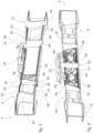
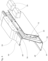
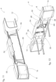
- reference numeral 4 indicates as a whole an overall view of a light bracket group for industrial vehicles.
- the light bracket group 4 comprises a pair of side modules 8, 12 having a main transverse extension X-X; each of said side modules 8, 12 supports at least one light 16 having signalling and/or lighting functions of the industrial vehicle.
- the light can comprise a direction indicator, a position light, a stop light, a reverse light, a side-marker, and the like.
- the light bracket group 4 further comprises a central module 20 arranged in an intermediate and contiguous position with respect to said side modules 8, 12.
- the central module 20 supports at least one identification plate of the industrial vehicle and preferably a lighting device 24 of said plate. Moreover, the central module 20 can also support further lighting and/or signalling lights and covers thereof.
- Each side module 8, 12 is provided with fixing means (not shown) to a chassis of the industrial vehicle, in particular to a bracket of said chassis.
- Said fixing means typically comprise screws, bolts, and the like.
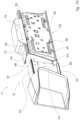
- the central module 20 in turn is fixed to the side modules 8, 12 by removable fixing means 28. Therefore, the central module 20 is not fixed to the chassis of the industrial vehicle, rather it is hooked and fixed to the side modules 8, 12, as better specified below.
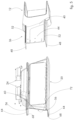
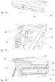
- the side modules 8, 12, at inner transverse ends 32, 36 facing the central module 20, have, with respect to a section plane perpendicular to said main transverse extension X-X, a body 40 with a "C"-shaped section having a vertical stretch 44 and two side edges 48 substantially perpendicular to the vertical stretch 44.
- the side edges 48 have raised profiles 52 which form transverse sliding rails for corresponding transverse seats 56 of the central module 20.
- said transverse seats 56 of the central module 20 are configured to achieve a shape coupling with said raised profiles 52 of the side edges 48.
- the central module 20 with respect to a section plane perpendicular to the main transverse extension X-X, comprises a "C"-shaped section having a vertical element 60 and a pair of horizontal branches 64 delimiting said transverse seats 56.
- said horizontal branches 64 of the central module 20 end with hooking appendages 68 configured to form a hook with free ends of the side edges 48 of the inner transverse ends 32, 36 of the side modules 8, 12.
- the inner transverse ends 32, 36 of the side modules 8, 12 are constrained with undercuts between the hooking appendages 68 and the transverse seats 56 of the central module 20.
- the vertical element 60 of the central module 20 comprises stiffening ribs 76 at a rear face 80 thereof.
- said stiffening ribs 76 are arranged along directions mutually crossed and angled with respect to the main transverse extension X-X.
- the removable fixing means 28 can comprise screws or pins engaged in slotted holes 84 parallel to said main transverse extension X-X.
- said screws or pins comprise elastically expandable heads or portions.
- each side module 8, 12 is fixed to the rear chassis of the industrial vehicle.
- each side module 8, 12 it is possible to fix each side module 8, 12 to a rear chassis of the industrial vehicle, this being followed by associating the central module 20 in an intermediate position between the side modules 8, 12 and fixing it to the inner transverse ends 32, 36 of said side modules 8, 12.
- Such a method provides for an elastically deformation of the central module 20 until it can be hooked at the back on the inner transverse ends 32, 36 of the side modules 8, 12, with particular reference to the hooking appendages 68.
- first side module 8 it is possible to fix a first side module 8 to a rear chassis of the industrial vehicle and associate the central module 20 with a first inner transverse end 32 of said first side module 8; this being followed by the step of fixing a second side module 12 to the rear chassis of the industrial vehicle and associating it, at a second transverse end 36 thereof, with said central module 20.
- the present invention allows overcoming the drawbacks presented in the prior art.
- the present invention allows obtaining the modularity of the components forming the light bracket group, which can thus be adapted to any transverse size of the industrial vehicle.
- the side modules do not vibrate and do not make noise when travelling, given that they are directly fixed to the chassis of the industrial vehicle.
- the central module which normally has the greater extension within the group, has no structural features that make it compact, and generally the entire light bracket group is significantly lighter than the solutions of the prior art.
- the mounting of the light bracket group is also practical and quick.
- the solution further allows replacing individual modules due to breaks, for example, or even disassembling individual modules for maintenance operations, for example.
Landscapes
- Engineering & Computer Science (AREA)
- Mechanical Engineering (AREA)
- Lighting Device Outwards From Vehicle And Optical Signal (AREA)
Claims (11)
- Lampenhaltergruppe (4) für Industriefahrzeuge, umfassend:- ein Paar von seitlichen Modulen (8, 12), welche eine transversale Haupterstreckung (X-X) aufweisen, wobei die seitlichen Module (8, 12) wenigstens eine Lampe haltern, welche Signal- und/oder Leuchtfunktionen des Industriefahrzeugs aufweist,- ein zentrales Modul (20), welches in Bezug auf die seitlichen Module (8, 12) in einer mittleren und angrenzenden Position angeordnet ist, wobei das zentrale Modul (20) wenigstens ein Identifikationsschild des Industriefahrzeugs haltert,- wobei jedes seitliche Modul (8, 12) mit Befestigungsmitteln für ein Chassis des Industriefahrzeugs bereitgestellt ist,- wobei das zentrale Modul (20) durch lösbare Befestigungsmittel (28) an den seitlichen Modulen (8, 12) befestigt ist,wobei die seitlichen Module (8, 12) an den inneren transversalen Enden (32, 36), welche dem zentralen Modul (20) zugewandt sind, in Bezug auf eine zu der transversalen Haupterstreckung (X-X) senkrechte Schnittebene einen Körper (40) mit einem "C"-Querschnitt aufweisen, welcher einen Abschnitt (44) vertikaler Ausdehnung und zwei seitliche Ränder (48) aufweist, welche im Wesentlichen senkrecht zu dem Abschnitt (44) vertikaler Ausdehnung sind, wobei die seitlichen Ränder (48) erhabene Profile (52) aufweisen, welche transversale Gleitschienen für entsprechende transversale Aufnahmen (56) des zentralen Moduls (20) schaffen,dadurch gekennzeichnet, dassdas zentrale Modul (20) in Bezug auf eine zu der transversalen Haupterstreckung (X-X) senkrechte Schnittebene einen "C"-Querschnitt umfasst, welcher ein vertikales Element (60) und ein Paar von horizontalen Abzweigungen (64) aufweist, welche die transversalen Aufnahmen (56) begrenzen,wobei in Bezug auf eine zu der transversalen Haupterstreckung (X-X) senkrechte Schnittebene die horizontalen Abzweigungen (64) des zentralen Moduls (20) mit Hakenfortsätzen (68) enden, welche dazu eingerichtet sind, einen Haken mit freien Enden der seitlichen Ränder (48) der inneren transversalen Enden (32, 36) der seitlichen Module (8, 12) zu schaffen.
- Lampenhaltergruppe (4) für Industriefahrzeuge nach Anspruch 1, wobei die transversalen Aufnahmen (56) des zentralen Moduls (20) dazu eingerichtet sind, eine Formkopplung mit den erhabenen Profilen (52) zu schaffen.
- Lampenhaltergruppe (4) für Industriefahrzeuge nach einem der vorhergehenden Ansprüche, wobei das zentrale Modul (20) zwischen dem vertikalen Element (60) und den Hakenfortsätzen (68) ein Volumen (72) begrenzt, welches dazu eingerichtet ist, die inneren transversalen Enden (32, 36) der seitlichen Module (8, 12) aufzunehmen.
- Lampenhaltergruppe (4) für Industriefahrzeuge nach Anspruch 1, 2 oder 3, wobei in der Baugruppenkonfiguration die inneren transversalen Enden (32, 36) der seitlichen Module (8, 12) mit Hinterschneidungen zwischen den Hakenfortsätzen (68) und den transversalen Aufnahmen (56) des zentralen Moduls (20) in Zwangsverbindung stehen.
- Lampenhaltergruppe (4) für Industriefahrzeuge nach einem der Ansprüche 1 bis 4, wobei ein vertikales Element (60) des zentralen Moduls (20) an einer hinteren Fläche davon Versteifungsrippen (76) umfasst.
- Lampenhaltergruppe (4) für Industriefahrzeuge nach Anspruch 5, wobei die Versteifungsrippen (76) entlang in Bezug auf die transversale Haupterstreckung (X-X) gekreuzten und winklig angeordneten Richtungen angeordnet sind.
- Lampenhaltergruppe (4) für Industriefahrzeuge nach einem der Ansprüche 1 bis 6, wobei die lösbaren Befestigungsmittel (28) Schrauben oder Stifte umfassen, welche in Langlöcher (84) eingreifen, die parallel zu der transversalen Haupterstreckung (X-X) sind.
- Lampenhaltergruppe (4) für Industriefahrzeuge nach Anspruch 7, wobei die Schrauben oder Stifte elastisch ausdehnbare Köpfe oder Abschnitte umfassen.
- Verfahren zum Montieren einer Lampenhaltergruppe (4) für Industriefahrzeuge, umfassend die folgenden Schritte:- Vorbereiten einer Lampenhaltergruppe (4) nach einem der Ansprüche 1 bis 8,- Zuordnen und Befestigen des zentralen Moduls (20) zwischen den seitlichen Modulen (8, 12) im Voraus, um die gesamte transversale Breite der Lampenhaltergruppe (4) anzupassen,- Befestigen jedes seitlichen Moduls (8, 12) an einem hinteren Chassis des Industriefahrzeugs.
- Verfahren zum Montieren einer Lampenhaltergruppe (4) für Industriefahrzeuge, umfassend die folgenden Schritte:- Vorbereiten einer Lampenhaltergruppe (4) nach einem der Ansprüche 1 bis 8,- Befestigen jedes seitlichen Moduls (8, 12) an einem hinteren Chassis des Industriefahrzeugs,- Zuordnen des zentralen Moduls (20) in einer Zwischenposition zwischen den seitlichen Modulen (8, 12) und Befestigen desselben an den inneren transversalen Enden (32, 36) der seitlichen Module (8, 12).
- Verfahren zum Montieren einer Lampenhaltergruppe (4) für Industriefahrzeuge, umfassend die folgenden Schritte:- Vorbereiten einer Lampenhaltergruppe (4) nach einem der Ansprüche 1 bis 8,- Befestigen eines ersten seitlichen Moduls (8) an einem hinteren Chassis des Industriefahrzeugs,- Zuordnen des zentralen Moduls (20) einem ersten inneren transversalen Ende (32) des ersten seitlichen Moduls (8),- Befestigen eines zweiten seitlichen Moduls (12) an einem hinteren Chassis des Industriefahrzeugs und Zuordnen desselben, an einem zweiten transversalen Ende (36) davon, dem zentralen Modul (20).
Applications Claiming Priority (1)
| Application Number | Priority Date | Filing Date | Title |
|---|---|---|---|
| IT102022000007709A IT202200007709A1 (it) | 2022-04-19 | 2022-04-19 | Gruppo portafanali modulare perfezionato e relativo metodo di montaggio |
Publications (2)
| Publication Number | Publication Date |
|---|---|
| EP4265478A1 EP4265478A1 (de) | 2023-10-25 |
| EP4265478B1 true EP4265478B1 (de) | 2024-12-04 |
Family
ID=82385537
Family Applications (1)
| Application Number | Title | Priority Date | Filing Date |
|---|---|---|---|
| EP23162370.3A Active EP4265478B1 (de) | 2022-04-19 | 2023-03-16 | Verbesserte modulare lichthalterungsgruppe und entsprechendes montageverfahren |
Country Status (3)
| Country | Link |
|---|---|
| EP (1) | EP4265478B1 (de) |
| IT (1) | IT202200007709A1 (de) |
| PL (1) | PL4265478T3 (de) |
Family Cites Families (4)
| Publication number | Priority date | Publication date | Assignee | Title |
|---|---|---|---|---|
| US3083292A (en) * | 1961-01-27 | 1963-03-26 | Charles A Roe | Trailer light support |
| FR2735733B1 (fr) * | 1995-06-22 | 1997-09-05 | Bernard Michel | Porte feux amovible et pliant pour remorque |
| NL1001182C2 (nl) * | 1995-09-13 | 1997-03-20 | Felua Groep | Verlichtingsarmatuur voor een voertuig. |
| ITTV20100043U1 (it) * | 2010-09-21 | 2012-03-22 | Lago Accessori S R L | Struttura di paraurti posteriore per veicoli |
-
2022
- 2022-04-19 IT IT102022000007709A patent/IT202200007709A1/it unknown
-
2023
- 2023-03-16 EP EP23162370.3A patent/EP4265478B1/de active Active
- 2023-03-16 PL PL23162370.3T patent/PL4265478T3/pl unknown
Also Published As
| Publication number | Publication date |
|---|---|
| IT202200007709A1 (it) | 2023-10-19 |
| EP4265478A1 (de) | 2023-10-25 |
| PL4265478T3 (pl) | 2025-04-28 |
Similar Documents
| Publication | Publication Date | Title |
|---|---|---|
| US10821903B2 (en) | Modular rail and step system | |
| CN202053950U (zh) | 机动车辆和用于机动车辆的外部后视镜 | |
| US7644966B2 (en) | Vehicle bumper fascia retainer | |
| US20110006553A1 (en) | Winch Carrier and Grille Guard Mounting System | |
| JP3740124B2 (ja) | コンバーチブル乗用車用車体およびモジュラーユニット | |
| US8184847B2 (en) | Vehicle speaker mounting system | |
| US11358520B2 (en) | Vehicle taillight assembly | |
| CN103661676A (zh) | 用于车辆的定位及加固结构 | |
| DE60220252D1 (de) | Frontanordnung für schwer-nutzfahrzeug | |
| EP4265478B1 (de) | Verbesserte modulare lichthalterungsgruppe und entsprechendes montageverfahren | |
| US10914448B2 (en) | Vehicle lamp installation method and assembly | |
| US20240375600A1 (en) | Bumper with selectively attachable light bars | |
| JPH06503776A (ja) | 車両ボディの懸架ばねのマウント | |
| US20050110245A1 (en) | Instrument panel adapter for airbag mount | |
| CN115743014B (zh) | 前保蒙皮总成、前保险杠总成及车辆 | |
| EP0604237A1 (de) | Kraftfahrzeugstossfängerbefestigung | |
| JP2003127811A (ja) | ラジエータグリルの取付構造 | |
| CN107792192A (zh) | 侧面部件以及具有侧面部件的车辆 | |
| JPH0270915A (ja) | 自動車の前部分 | |
| JPH03213472A (ja) | 自動車の前部車体構造及びその組立方法 | |
| JP2002096760A (ja) | 車両フロントエンドモジュール装置 | |
| US20260001502A1 (en) | Front bumper assembly | |
| US11001321B2 (en) | Apparatus for supporting a component mounting plate between trailer beams | |
| US20210016714A1 (en) | Running Board | |
| KR100380052B1 (ko) | 차량용 통합 빔 구조 |
Legal Events
| Date | Code | Title | Description |
|---|---|---|---|
| STAA | Information on the status of an ep patent application or granted ep patent |
Free format text: STATUS: THE APPLICATION HAS BEEN PUBLISHED |
|
| PUAI | Public reference made under article 153(3) epc to a published international application that has entered the european phase |
Free format text: ORIGINAL CODE: 0009012 |
|
| AK | Designated contracting states |
Kind code of ref document: A1 Designated state(s): AL AT BE BG CH CY CZ DE DK EE ES FI FR GB GR HR HU IE IS IT LI LT LU LV MC ME MK MT NL NO PL PT RO RS SE SI SK SM TR |
|
| P01 | Opt-out of the competence of the unified patent court (upc) registered |
Effective date: 20231213 |
|
| STAA | Information on the status of an ep patent application or granted ep patent |
Free format text: STATUS: REQUEST FOR EXAMINATION WAS MADE |
|
| 17P | Request for examination filed |
Effective date: 20240321 |
|
| RBV | Designated contracting states (corrected) |
Designated state(s): AL AT BE BG CH CY CZ DE DK EE ES FI FR GB GR HR HU IE IS IT LI LT LU LV MC ME MK MT NL NO PL PT RO RS SE SI SK SM TR |
|
| GRAP | Despatch of communication of intention to grant a patent |
Free format text: ORIGINAL CODE: EPIDOSNIGR1 |
|
| STAA | Information on the status of an ep patent application or granted ep patent |
Free format text: STATUS: GRANT OF PATENT IS INTENDED |
|
| INTG | Intention to grant announced |
Effective date: 20240724 |
|
| GRAS | Grant fee paid |
Free format text: ORIGINAL CODE: EPIDOSNIGR3 |
|
| GRAA | (expected) grant |
Free format text: ORIGINAL CODE: 0009210 |
|
| STAA | Information on the status of an ep patent application or granted ep patent |
Free format text: STATUS: THE PATENT HAS BEEN GRANTED |
|
| AK | Designated contracting states |
Kind code of ref document: B1 Designated state(s): AL AT BE BG CH CY CZ DE DK EE ES FI FR GB GR HR HU IE IS IT LI LT LU LV MC ME MK MT NL NO PL PT RO RS SE SI SK SM TR |
|
| REG | Reference to a national code |
Ref country code: CH Ref legal event code: EP |
|
| REG | Reference to a national code |
Ref country code: DE Ref legal event code: R096 Ref document number: 602023001213 Country of ref document: DE |
|
| REG | Reference to a national code |
Ref country code: IE Ref legal event code: FG4D |
|
| REG | Reference to a national code |
Ref country code: NL Ref legal event code: FP |
|
| REG | Reference to a national code |
Ref country code: LT Ref legal event code: MG9D |
|
| PG25 | Lapsed in a contracting state [announced via postgrant information from national office to epo] |
Ref country code: HR Free format text: LAPSE BECAUSE OF FAILURE TO SUBMIT A TRANSLATION OF THE DESCRIPTION OR TO PAY THE FEE WITHIN THE PRESCRIBED TIME-LIMIT Effective date: 20241204 |
|
| PG25 | Lapsed in a contracting state [announced via postgrant information from national office to epo] |
Ref country code: FI Free format text: LAPSE BECAUSE OF FAILURE TO SUBMIT A TRANSLATION OF THE DESCRIPTION OR TO PAY THE FEE WITHIN THE PRESCRIBED TIME-LIMIT Effective date: 20241204 |
|
| PG25 | Lapsed in a contracting state [announced via postgrant information from national office to epo] |
Ref country code: BG Free format text: LAPSE BECAUSE OF FAILURE TO SUBMIT A TRANSLATION OF THE DESCRIPTION OR TO PAY THE FEE WITHIN THE PRESCRIBED TIME-LIMIT Effective date: 20241204 |
|
| PG25 | Lapsed in a contracting state [announced via postgrant information from national office to epo] |
Ref country code: ES Free format text: LAPSE BECAUSE OF FAILURE TO SUBMIT A TRANSLATION OF THE DESCRIPTION OR TO PAY THE FEE WITHIN THE PRESCRIBED TIME-LIMIT Effective date: 20241204 |
|
| PG25 | Lapsed in a contracting state [announced via postgrant information from national office to epo] |
Ref country code: NO Free format text: LAPSE BECAUSE OF FAILURE TO SUBMIT A TRANSLATION OF THE DESCRIPTION OR TO PAY THE FEE WITHIN THE PRESCRIBED TIME-LIMIT Effective date: 20250304 |
|
| PG25 | Lapsed in a contracting state [announced via postgrant information from national office to epo] |
Ref country code: GR Free format text: LAPSE BECAUSE OF FAILURE TO SUBMIT A TRANSLATION OF THE DESCRIPTION OR TO PAY THE FEE WITHIN THE PRESCRIBED TIME-LIMIT Effective date: 20250305 Ref country code: LV Free format text: LAPSE BECAUSE OF FAILURE TO SUBMIT A TRANSLATION OF THE DESCRIPTION OR TO PAY THE FEE WITHIN THE PRESCRIBED TIME-LIMIT Effective date: 20241204 |
|
| PG25 | Lapsed in a contracting state [announced via postgrant information from national office to epo] |
Ref country code: RS Free format text: LAPSE BECAUSE OF FAILURE TO SUBMIT A TRANSLATION OF THE DESCRIPTION OR TO PAY THE FEE WITHIN THE PRESCRIBED TIME-LIMIT Effective date: 20250304 |
|
| REG | Reference to a national code |
Ref country code: AT Ref legal event code: MK05 Ref document number: 1747844 Country of ref document: AT Kind code of ref document: T Effective date: 20241204 |
|
| PG25 | Lapsed in a contracting state [announced via postgrant information from national office to epo] |
Ref country code: SM Free format text: LAPSE BECAUSE OF FAILURE TO SUBMIT A TRANSLATION OF THE DESCRIPTION OR TO PAY THE FEE WITHIN THE PRESCRIBED TIME-LIMIT Effective date: 20241204 |
|
| PG25 | Lapsed in a contracting state [announced via postgrant information from national office to epo] |
Ref country code: IS Free format text: LAPSE BECAUSE OF FAILURE TO SUBMIT A TRANSLATION OF THE DESCRIPTION OR TO PAY THE FEE WITHIN THE PRESCRIBED TIME-LIMIT Effective date: 20250404 |
|
| PGFP | Annual fee paid to national office [announced via postgrant information from national office to epo] |
Ref country code: IT Payment date: 20250331 Year of fee payment: 3 |
|
| PG25 | Lapsed in a contracting state [announced via postgrant information from national office to epo] |
Ref country code: PT Free format text: LAPSE BECAUSE OF FAILURE TO SUBMIT A TRANSLATION OF THE DESCRIPTION OR TO PAY THE FEE WITHIN THE PRESCRIBED TIME-LIMIT Effective date: 20250404 |
|
| PG25 | Lapsed in a contracting state [announced via postgrant information from national office to epo] |
Ref country code: EE Free format text: LAPSE BECAUSE OF FAILURE TO SUBMIT A TRANSLATION OF THE DESCRIPTION OR TO PAY THE FEE WITHIN THE PRESCRIBED TIME-LIMIT Effective date: 20241204 |
|
| PG25 | Lapsed in a contracting state [announced via postgrant information from national office to epo] |
Ref country code: AT Free format text: LAPSE BECAUSE OF FAILURE TO SUBMIT A TRANSLATION OF THE DESCRIPTION OR TO PAY THE FEE WITHIN THE PRESCRIBED TIME-LIMIT Effective date: 20241204 Ref country code: RO Free format text: LAPSE BECAUSE OF FAILURE TO SUBMIT A TRANSLATION OF THE DESCRIPTION OR TO PAY THE FEE WITHIN THE PRESCRIBED TIME-LIMIT Effective date: 20241204 |
|
| PG25 | Lapsed in a contracting state [announced via postgrant information from national office to epo] |
Ref country code: SK Free format text: LAPSE BECAUSE OF FAILURE TO SUBMIT A TRANSLATION OF THE DESCRIPTION OR TO PAY THE FEE WITHIN THE PRESCRIBED TIME-LIMIT Effective date: 20241204 |
|
| PG25 | Lapsed in a contracting state [announced via postgrant information from national office to epo] |
Ref country code: CZ Free format text: LAPSE BECAUSE OF FAILURE TO SUBMIT A TRANSLATION OF THE DESCRIPTION OR TO PAY THE FEE WITHIN THE PRESCRIBED TIME-LIMIT Effective date: 20241204 |
|
| REG | Reference to a national code |
Ref country code: DE Ref legal event code: R097 Ref document number: 602023001213 Country of ref document: DE |
|
| PG25 | Lapsed in a contracting state [announced via postgrant information from national office to epo] |
Ref country code: SE Free format text: LAPSE BECAUSE OF FAILURE TO SUBMIT A TRANSLATION OF THE DESCRIPTION OR TO PAY THE FEE WITHIN THE PRESCRIBED TIME-LIMIT Effective date: 20241204 |
|
| PG25 | Lapsed in a contracting state [announced via postgrant information from national office to epo] |
Ref country code: DK Free format text: LAPSE BECAUSE OF FAILURE TO SUBMIT A TRANSLATION OF THE DESCRIPTION OR TO PAY THE FEE WITHIN THE PRESCRIBED TIME-LIMIT Effective date: 20241204 |
|
| PLBE | No opposition filed within time limit |
Free format text: ORIGINAL CODE: 0009261 |
|
| STAA | Information on the status of an ep patent application or granted ep patent |
Free format text: STATUS: NO OPPOSITION FILED WITHIN TIME LIMIT |
|
| PG25 | Lapsed in a contracting state [announced via postgrant information from national office to epo] |
Ref country code: MC Free format text: LAPSE BECAUSE OF FAILURE TO SUBMIT A TRANSLATION OF THE DESCRIPTION OR TO PAY THE FEE WITHIN THE PRESCRIBED TIME-LIMIT Effective date: 20241204 |
|
| 26N | No opposition filed |
Effective date: 20250905 |
|
| PG25 | Lapsed in a contracting state [announced via postgrant information from national office to epo] |
Ref country code: LU Free format text: LAPSE BECAUSE OF NON-PAYMENT OF DUE FEES Effective date: 20250316 |
|
| PG25 | Lapsed in a contracting state [announced via postgrant information from national office to epo] |
Ref country code: FR Free format text: LAPSE BECAUSE OF NON-PAYMENT OF DUE FEES Effective date: 20250331 |
|
| PG25 | Lapsed in a contracting state [announced via postgrant information from national office to epo] |
Ref country code: IE Free format text: LAPSE BECAUSE OF NON-PAYMENT OF DUE FEES Effective date: 20250316 |
|
| PGFP | Annual fee paid to national office [announced via postgrant information from national office to epo] |
Ref country code: DE Payment date: 20260325 Year of fee payment: 4 |
|
| PGFP | Annual fee paid to national office [announced via postgrant information from national office to epo] |
Ref country code: BE Payment date: 20260319 Year of fee payment: 4 |
|
| PGFP | Annual fee paid to national office [announced via postgrant information from national office to epo] |
Ref country code: NL Payment date: 20260323 Year of fee payment: 4 |
|
| PGFP | Annual fee paid to national office [announced via postgrant information from national office to epo] |
Ref country code: PL Payment date: 20260303 Year of fee payment: 4 |