EP4263303B1 - Anhängerbremssteuerungssystem - Google Patents
Anhängerbremssteuerungssystem Download PDFInfo
- Publication number
- EP4263303B1 EP4263303B1 EP21819590.7A EP21819590A EP4263303B1 EP 4263303 B1 EP4263303 B1 EP 4263303B1 EP 21819590 A EP21819590 A EP 21819590A EP 4263303 B1 EP4263303 B1 EP 4263303B1
- Authority
- EP
- European Patent Office
- Prior art keywords
- brake
- trailer
- valve
- control
- vehicle
- Prior art date
- Legal status (The legal status is an assumption and is not a legal conclusion. Google has not performed a legal analysis and makes no representation as to the accuracy of the status listed.)
- Active
Links
Images

Classifications
-
- B—PERFORMING OPERATIONS; TRANSPORTING
- B60—VEHICLES IN GENERAL
- B60T—VEHICLE BRAKE CONTROL SYSTEMS OR PARTS THEREOF; BRAKE CONTROL SYSTEMS OR PARTS THEREOF, IN GENERAL; ARRANGEMENT OF BRAKING ELEMENTS ON VEHICLES IN GENERAL; PORTABLE DEVICES FOR PREVENTING UNWANTED MOVEMENT OF VEHICLES; VEHICLE MODIFICATIONS TO FACILITATE COOLING OF BRAKES
- B60T11/00—Transmitting braking action from initiating means to ultimate brake actuator without power assistance or drive or where such assistance or drive is irrelevant
- B60T11/10—Transmitting braking action from initiating means to ultimate brake actuator without power assistance or drive or where such assistance or drive is irrelevant transmitting by fluid means, e.g. hydraulic
- B60T11/108—Transmitting braking action from initiating means to ultimate brake actuator without power assistance or drive or where such assistance or drive is irrelevant transmitting by fluid means, e.g. hydraulic to a trailer fluid system
-
- B—PERFORMING OPERATIONS; TRANSPORTING
- B60—VEHICLES IN GENERAL
- B60T—VEHICLE BRAKE CONTROL SYSTEMS OR PARTS THEREOF; BRAKE CONTROL SYSTEMS OR PARTS THEREOF, IN GENERAL; ARRANGEMENT OF BRAKING ELEMENTS ON VEHICLES IN GENERAL; PORTABLE DEVICES FOR PREVENTING UNWANTED MOVEMENT OF VEHICLES; VEHICLE MODIFICATIONS TO FACILITATE COOLING OF BRAKES
- B60T13/00—Transmitting braking action from initiating means to ultimate brake actuator with power assistance or drive; Brake systems incorporating such transmitting means, e.g. air-pressure brake systems
- B60T13/10—Transmitting braking action from initiating means to ultimate brake actuator with power assistance or drive; Brake systems incorporating such transmitting means, e.g. air-pressure brake systems with fluid assistance, drive, or release
- B60T13/24—Transmitting braking action from initiating means to ultimate brake actuator with power assistance or drive; Brake systems incorporating such transmitting means, e.g. air-pressure brake systems with fluid assistance, drive, or release the fluid being gaseous
- B60T13/26—Compressed-air systems
- B60T13/268—Compressed-air systems using accumulators or reservoirs
-
- B—PERFORMING OPERATIONS; TRANSPORTING
- B60—VEHICLES IN GENERAL
- B60T—VEHICLE BRAKE CONTROL SYSTEMS OR PARTS THEREOF; BRAKE CONTROL SYSTEMS OR PARTS THEREOF, IN GENERAL; ARRANGEMENT OF BRAKING ELEMENTS ON VEHICLES IN GENERAL; PORTABLE DEVICES FOR PREVENTING UNWANTED MOVEMENT OF VEHICLES; VEHICLE MODIFICATIONS TO FACILITATE COOLING OF BRAKES
- B60T13/00—Transmitting braking action from initiating means to ultimate brake actuator with power assistance or drive; Brake systems incorporating such transmitting means, e.g. air-pressure brake systems
- B60T13/10—Transmitting braking action from initiating means to ultimate brake actuator with power assistance or drive; Brake systems incorporating such transmitting means, e.g. air-pressure brake systems with fluid assistance, drive, or release
- B60T13/58—Combined or convertible systems
- B60T13/581—Combined or convertible systems both hydraulic and pneumatic
-
- B—PERFORMING OPERATIONS; TRANSPORTING
- B60—VEHICLES IN GENERAL
- B60T—VEHICLE BRAKE CONTROL SYSTEMS OR PARTS THEREOF; BRAKE CONTROL SYSTEMS OR PARTS THEREOF, IN GENERAL; ARRANGEMENT OF BRAKING ELEMENTS ON VEHICLES IN GENERAL; PORTABLE DEVICES FOR PREVENTING UNWANTED MOVEMENT OF VEHICLES; VEHICLE MODIFICATIONS TO FACILITATE COOLING OF BRAKES
- B60T17/00—Component parts, details, or accessories of power brake systems not covered by groups B60T8/00, B60T13/00 or B60T15/00, or presenting other characteristic features
- B60T17/18—Safety devices; Monitoring
- B60T17/22—Devices for monitoring or checking brake systems; Signal devices
-
- B—PERFORMING OPERATIONS; TRANSPORTING
- B60—VEHICLES IN GENERAL
- B60T—VEHICLE BRAKE CONTROL SYSTEMS OR PARTS THEREOF; BRAKE CONTROL SYSTEMS OR PARTS THEREOF, IN GENERAL; ARRANGEMENT OF BRAKING ELEMENTS ON VEHICLES IN GENERAL; PORTABLE DEVICES FOR PREVENTING UNWANTED MOVEMENT OF VEHICLES; VEHICLE MODIFICATIONS TO FACILITATE COOLING OF BRAKES
- B60T7/00—Brake-action initiating means
- B60T7/12—Brake-action initiating means for automatic initiation; for initiation not subject to will of driver or passenger
- B60T7/20—Brake-action initiating means for automatic initiation; for initiation not subject to will of driver or passenger specially for trailers, e.g. in case of uncoupling of or overrunning by trailer
-
- B—PERFORMING OPERATIONS; TRANSPORTING
- B60—VEHICLES IN GENERAL
- B60T—VEHICLE BRAKE CONTROL SYSTEMS OR PARTS THEREOF; BRAKE CONTROL SYSTEMS OR PARTS THEREOF, IN GENERAL; ARRANGEMENT OF BRAKING ELEMENTS ON VEHICLES IN GENERAL; PORTABLE DEVICES FOR PREVENTING UNWANTED MOVEMENT OF VEHICLES; VEHICLE MODIFICATIONS TO FACILITATE COOLING OF BRAKES
- B60T8/00—Arrangements for adjusting wheel-braking force to meet varying vehicular or ground-surface conditions, e.g. limiting or varying distribution of braking force
- B60T8/17—Using electrical or electronic regulation means to control braking
- B60T8/1701—Braking or traction control means specially adapted for particular types of vehicles
-
- B—PERFORMING OPERATIONS; TRANSPORTING
- B60—VEHICLES IN GENERAL
- B60T—VEHICLE BRAKE CONTROL SYSTEMS OR PARTS THEREOF; BRAKE CONTROL SYSTEMS OR PARTS THEREOF, IN GENERAL; ARRANGEMENT OF BRAKING ELEMENTS ON VEHICLES IN GENERAL; PORTABLE DEVICES FOR PREVENTING UNWANTED MOVEMENT OF VEHICLES; VEHICLE MODIFICATIONS TO FACILITATE COOLING OF BRAKES
- B60T8/00—Arrangements for adjusting wheel-braking force to meet varying vehicular or ground-surface conditions, e.g. limiting or varying distribution of braking force
- B60T8/32—Arrangements for adjusting wheel-braking force to meet varying vehicular or ground-surface conditions, e.g. limiting or varying distribution of braking force responsive to a speed condition, e.g. acceleration or deceleration
- B60T8/34—Arrangements for adjusting wheel-braking force to meet varying vehicular or ground-surface conditions, e.g. limiting or varying distribution of braking force responsive to a speed condition, e.g. acceleration or deceleration having a fluid pressure regulator responsive to a speed condition
- B60T8/36—Arrangements for adjusting wheel-braking force to meet varying vehicular or ground-surface conditions, e.g. limiting or varying distribution of braking force responsive to a speed condition, e.g. acceleration or deceleration having a fluid pressure regulator responsive to a speed condition including a pilot valve responding to an electromagnetic force
- B60T8/3605—Arrangements for adjusting wheel-braking force to meet varying vehicular or ground-surface conditions, e.g. limiting or varying distribution of braking force responsive to a speed condition, e.g. acceleration or deceleration having a fluid pressure regulator responsive to a speed condition including a pilot valve responding to an electromagnetic force wherein the pilot valve is mounted in a circuit controlling the working fluid system
-
- B—PERFORMING OPERATIONS; TRANSPORTING
- B60—VEHICLES IN GENERAL
- B60T—VEHICLE BRAKE CONTROL SYSTEMS OR PARTS THEREOF; BRAKE CONTROL SYSTEMS OR PARTS THEREOF, IN GENERAL; ARRANGEMENT OF BRAKING ELEMENTS ON VEHICLES IN GENERAL; PORTABLE DEVICES FOR PREVENTING UNWANTED MOVEMENT OF VEHICLES; VEHICLE MODIFICATIONS TO FACILITATE COOLING OF BRAKES
- B60T13/00—Transmitting braking action from initiating means to ultimate brake actuator with power assistance or drive; Brake systems incorporating such transmitting means, e.g. air-pressure brake systems
- B60T13/10—Transmitting braking action from initiating means to ultimate brake actuator with power assistance or drive; Brake systems incorporating such transmitting means, e.g. air-pressure brake systems with fluid assistance, drive, or release
- B60T13/66—Electrical control in fluid-pressure brake systems
- B60T13/68—Electrical control in fluid-pressure brake systems by electrically-controlled valves
- B60T13/683—Electrical control in fluid-pressure brake systems by electrically-controlled valves in pneumatic systems or parts thereof
-
- B—PERFORMING OPERATIONS; TRANSPORTING
- B60—VEHICLES IN GENERAL
- B60T—VEHICLE BRAKE CONTROL SYSTEMS OR PARTS THEREOF; BRAKE CONTROL SYSTEMS OR PARTS THEREOF, IN GENERAL; ARRANGEMENT OF BRAKING ELEMENTS ON VEHICLES IN GENERAL; PORTABLE DEVICES FOR PREVENTING UNWANTED MOVEMENT OF VEHICLES; VEHICLE MODIFICATIONS TO FACILITATE COOLING OF BRAKES
- B60T2270/00—Further aspects of brake control systems not otherwise provided for
- B60T2270/88—Pressure measurement in brake systems
Definitions
- the present invention relates to a trailer brake control system for a vehicle.
- the invention relates in particular to a trailer brake control system for an agricultural vehicle such as a tractor.
- trailers for the transportation of goods and materials.
- trailers may be provided with braking systems to allow for safe control of the trailer, and to prevent jack-knifing or skidding of the trailer when braking.
- the brake system on the trailer is coupled to an output from a trailer brake control system forming part of the towing vehicle brake system and which provides a fluid pressure signal for actuating the brakes on the trailer.
- the fluid pressure forwarded to the brakes of both the towing vehicle and the trailer is not determined solely in response to pressure applied to a brake pedal. Rather, the pressure forwarded to the brakes is adjusted by an electronic control unit (ECU).
- ECU electronice control unit
- the ECU can be programmed to regulate the applied brake force taking into account inputs provided by various sensors which are indicative of the operative conditions of the vehicle and trailer and other factors.
- Electronic trailer brake control systems are especially advantageous in avoiding jack-knifing.
- an electronic trailer brake control system can be configured to activate the brakes on the trailer when a potential jack-knifing situation is detected.
- trucks are usually equipped with dual service brake systems wherein two separate circuits are activated independently when the brake pedal is depressed.
- a first circuit may thereby act on e.g. the right front wheel and the left rear wheel (or the left wheels of tandem rear axle) while a second circuit acts the left front wheel and the right rear wheel (or the right wheels of tandem rear axle). If one of the circuits fail, the other circuit can still provide sufficient brake force to the safely decelerate the vehicle.
- Electronic trailer brake control systems are less commonly used on agricultural vehicles, such as tractors, for a number of reasons:
- a vehicle brake system comprising:
- the electronic trailer brake control system is able to control actuation of the service brake function on a trailer towed by the vehicle. Actuation of the electronic trailer brake control system generates a fluid pressure at the trailer control coupling which is forwarded as a service brake demand to the brake system on the trailer.
- the electronic trailer brake control system can be used to reduce the risk of jack-knifing, for example.
- tractor as used herein should be understood as encompassing any suitable unpowered vehicle or implement with a suitable braking system which can be controlled through the brake system of the towing vehicle when suitably coupled.
- the electronic trailer brake control system comprises an electronic control system including an electronic control unit (ECU) or controller, the ECU being configured in use to actuate the control valve in order to supply pressurised fluid indicative of a service brake demand for the trailer to the trailer brake control coupling in dependence on one or more operational conditions of the vehicle and/or a trailer towed by the vehicle being met.
- the ECU may be configured in use to actuate the control valve in order to supply pressurised fluid indicative of a service brake demand for the trailer to the trailer brake control coupling in dependence on one or more operational conditions of the vehicle and/or a trailer towed by the vehicle indicative of a PUSH condition being met.
- the control valve may comprise a solenoid valve actuatable under control of the electronic control system and operative to cause a pressurised fluid indicative of a service brake demand for the trailer to be forwarded to the trailer brake control coupling.
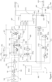
- the air supply system 100 comprises an air compressor 110, an air drier unit 120 and a prioritisation valve arrangement 130.
- the air compressor 110 driven by the combustion engine of the vehicle (or any prime mover such as an electric motor) supplies air into the air drier unit 120, which includes a reservoir to store compressed air and a granule cartridge to extract water from the air.
- compressed air is passed through the prioritisation valve arrangement 130 which is configured to prioritise supply to primary consumers of the vehicle over the supply to secondary consumers.
- Primary consumers include safety critical systems such as the park brake system 300, the trailer brake control system 400, and the electronic trailer brake system 500.
- Secondary consumers are not shown for clarity reasons but might include a tyre pressure control system (TPCS) or a cleaning system for an engine air filter, for example.
- TPCS tyre pressure control system
- the prioritisation valve arrangement 130 is operative to maintain the integrity of the primary consumers in the event that the air supply is not capable of meeting all demands.
- the tractor air supply system 100 as shown in Figure 2 is an illustrative example only and could be replaced by any other suitable air supply system.
- an air supply system such as that described in the Applicant's published patent application WO 2011/001261 , which comprises an additional higher flow rate compressor could be adopted.
- the service brake system 200 includes a service brake circuit 221 with a brake master cylinder 210 operated by a brake pedal 212 depressed by the foot of an operator to generate a fluid pressure in the service brake circuit 221.
- the fluid pressure generated in the service brake circuit 221 is dependent on the pressure applied by the operator to brake pedal and is indicative of a brake demand by the operator. This fluid pressure will, therefore, be referred to as a Service Brake Demand Signal (SBDS).
- SBDS Service Brake Demand Signal
- the service brake circuit 221 may include brake boosters supplied with hydraulic fluid under pressure by a hydraulic pump (not shown) so that the hydraulic pressure applied at the brake actuators is higher than that produced by the operator pressing on the brake pedal.
- Figure 2 shows a single service brake circuit 221, there may be more than one service brake circuit in a brake system 10 according to the invention.
- the service brake system 200 could have two separate service brake circuits 221 each operatively connected with a separate brake master cylinder which are actuated from a single brake pedal 212. This provides for redundancy in case one of the circuits fails.
- a first service brake circuit may be hydraulically connected to the brake actuators on the rear axle 5 while a second service brake circuit is hydraulically connected to the brake actuators of the front axle 4.
- the other circuit can still be pressurised to provide braking capability.
- the park brake system 300 as illustrated is actuated mechanically by the park brake lever.
- alternative park brake systems could be employed.
- a pneumatic park brake system which allows for electronic control of the park brake such as that described in the applicant's published patent EP2982555 B1 could be used.
- the brakes on the trailer are pneumatic.
- the lever is operatively connected with a park brake valve 320.
- the park brake valve 320 is connected to joint supply line 172 and is configured to selectively connect or disconnect the joint supply line 172 with a park brake circuit 330.
- the park brake circuit 330 provides a park brake demand signal PBDS for actuating the brakes on the trailer as will be described in detail below.
- references herein to a "brake demand” or “brake demand signal” in relation to a pneumatic or hydraulic line or circuit should be understood as referring to a pressure of the fluid in the line or circuit which is indicative of a required braking force.
- the trailer brake control system 400 is provided with a trailer brake valve 410 to control application of the brakes on a trailer in dependence on brake demand signal SBDS or PBDS received from the service brake system 200 and/or the park brake circuit 330.
- Trailer brake valve 410 also forwards compressed air to the air supply of the trailer.
- the pneumatic system of the trailer (not shown) is connected via standardized trailer couplings 420, 430. These include a trailer supply coupling 420 and a trailer brake control coupling 430.
- the trailer supply coupling 420 is usually colour coded red and provides general air supply to the trailer including its brake system and any other consumers.
- the trailer brake control coupling 430 is usually colour coded yellow and is provided to forward a trailer service brake demand signal TSBDS to the trailer brake system.
- the brake system on the trailer may have combined brake units which have a first, service brake actuator responsive to applied air pressure to apply a braking force to provide a service brake function and a second, park brake actuator which is spring biased to apply a braking force to provide a park brake function.
- the park brake actuator is held in a brake released position by air pressure from the internal air supply reservoir on the trailer when the park brakes are deactivated. If the internal air supply reservoir on the trailer is discharged, the spring load applies the full brake force.
- the trailer supply coupling 420 is normally connected to the internal air supply reservoir on the trailer via a brake valve on the trailer. The pressure applied to the brake valve on the trailer through the trailer supply coupling 420 provides the park brake functionality on the trailer.
- the trailer brake control coupling 430 is also connected to the brake valve on the trailer.
- the trailer service brake demand fluid pressure signal TSBDS provided through the brake control coupling 430 pilot-controls the brake valve of the trailer to generate a controlled brake pressure forwarded to the service brake actuators of the combined brake units which apply a corresponding service brake force to the wheels of the trailer.
- the trailer brake valve has six ports 401a to 401f.
- the third port 410c is operatively connected to first service brake circuit 221 via first service brake input line 445. This port receives the service brake demand signal (hydraulic fluid pressure) SBDS from the service brake circuit 221 and will be referred to as a service brake demand input port.
- service brake demand signal hydraulic fluid pressure
- the fourth port 410d is operatively connected to the park brake circuit 330 via park brake demand input line 450 and a first shuttle valve 472 to receive a park brake demand signal (air pressure) PBDS from the park brake circuit 330.
- the fourth port 410d will be referred to as a park brake demand input port.
- the park brake valve 320 is operatively connected with the park brake lever 310 and is configured to selectively connect or disconnect the joint supply line 172 with the park brake circuit 330 in response to actuation of the park brake lever 310.
- the park brake valve 320 is movable between a first position 320a as shown in Figure 2 in which the park brake circuit 330 is connected with the joint supply line 172 and so is pressurised. If the park brake lever 310 is moved to a park brake on position, this moves the park brake valve to a second position 320b in which the park brake circuit 330 is vented to ambient and so depressurised.
- the pressure in the park brake circuit is forward to the park brake demand input port 410d as a park brake demand signal PBDS through the first shuttle valve 472 and the park brake demand input line 450.
- the park brake valve 320 is biased to the first position 320a so that the park brake circuit 330 and the park brake demand input line 450 are pressurised in the event that the connection between the park brake leaver and the valve fails. This ensures that the service brakes on the trailer are not unintentionally applied in these circumstances.
- the service brake demand signal SBDS and the park brake demand signal PBDS control an internal relay of valve 410 (not shown in detail) which generates a trailer service brake demand signal (air pressure) TSBDS which is forwarded to the trailer brake control coupling 430 through the fifth port 410e to control the service brake functionality of the trailer.
- the fifth port 410e will be referred to as the trailer service brake demand output port.
- the trailer brake valve 410 provides a TSBDS output at port 410e which is inversely proportional to the air pressure at port 410d, this will result in a high pressure TSBDS at the port 410e which is forwarded to the brake valve on the trailer so that the service brake actuators on the trailer are actuated to apply a high braking force. Accordingly, the service brake actuators are activated to provide a braking force when the park brakes are applied on the towing vehicle, provided the trailer remains pneumatically coupled to the towing vehicle.
- the ability to generate a TSBDS through port 410e by use of the park brake system 300 on the vehicle is beneficial in providing an emergency braking arrangement in the event the service brakes on the vehicle should fail.
- the driver can attempt to slow the vehicle by applying the park brakes on the towing vehicle using the lever 310.
- This moves the park brake valve 320 to a position in between first position 320a and second position 320b to manually reduce the air pressure in the park brake circuit 330.
- the trailer brake valve 410 provides a TSBDS output at port 410e which is inversely proportional to the reducing air pressure in the park brake circuit 330 so that the service brake actuators on the trailer are actuated in a controlled manner to provide a braking force.
- a sixth port 410f is used to provide a pre-pressurisation function.
- the hydraulic service brake circuit 221 works with relative low volumes of fluid in comparison with the pneumatic brake systems.
- a pre-pressurisation system 600 is operative to provide a basic level of air pressurisation to the trailer service brake demand output port 410e when the brake pedal is depressed, prior to the hydraulic pressure in the service brake circuit 221 building up.
- the pre-pressurisation port 410f is connected with the joint supply line 172 though a pre-pressurisation valve 610 and a pre-pressurisation pressure relief valve 620.
- the valve 610 is a solenoid valve which is biased to a first position 610a, as shown in Figure 2 , in which a pre-pressurisation line 630 to the pre-pressurisation port is not connected with the joint supply line.
- the pre-presurisation valve 610 When activated, the pre-presurisation valve 610 is moved to a second position in which the pre-pressurisation line 630 is connected with the joint supply line.
- This pressurises the pre-pressurisation line 630 and the fluid pressured applied at port 410f controls an internal relay of valve 410 (not shown in detail) which generates pre-pressurisation trailer service brake demand signal (air pressure) at the trailer service brake demand outlet port 410e.
- Actuation of the pre-presurisation valve 610 is controlled by the ECU in response to a signal from a brake pedal switch 214.
- the switch 214 sends a signal to the ECU to indicate that a service brake demand is being generated.
- the ECU 12 actuates the pre-presurisation valve 610 to pre-pressurise the service brakes on the trailer.
- the pre-pressurisation valve 620 is deactivated and moves back to its first position.
- the pre-pressurisation pressure relief valve 620 is included to limit the pressure applied at the pre-pressurisation port when the valve 610 is open.
- the trailer brake valve 410 may have provision for responding to critical driving situations in case of breakaway at trailer couplings 420,430. Furthermore, the trailer brake valve 410 may have provision to adjust the advancement of the trailer brake so that when the service brake on the vehicle is activated only slightly, a slightly higher pressure is applied to the trailer to ensure that the trailer brakes are operated prior to the service brake of the tractor. This reduces the risk of the trailer pushing the tractor which could lead to jack-knifing. In known arrangements, the degree of advancement can be set manually at the trailer brake valve 410.
- Trailer brake valves 410 of the type described and which produce a fluid pressure output at the trailer brake demand output port which is dependent on the fluid pressure applied at a brake demand input port are well known in the art and details of the valve will not be described further.
- the trailer brake control system 400 is provided with an additional control circuit 470 operative to inhibit operation of the trailer brakes when activated. This is provided so that the driver is able to test whether the towing vehicle is capable of holding the trailer using only the brakes on the towing vehicle. During the test, the vehicle is not allowed to move.
- RVBR vehicle braking requirements
- the additional control circuit 470 comprises a test valve 471 connected to the air supply system via the joint supply line 172 and to a first inlet of the first shuttle valve 472 by a test control line 473.
- a second inlet to the first shuttle valve 472 is connected to the park brake circuit 330.
- the output side of the first shuttle valve 472 is connected to port 410d of the trailer brake valve 410 via the park brake demand (PBDS) input line 450.
- PBDS park brake demand
- the first shuttle valve 472 provides a pneumatic OR functionality (i.e., logic control) to forward either of the pressure in the park brake circuit 330 or the pressure in control line 473, whichever is at greater pressure.
- the test valve 417 is solenoid controlled and connected to the ECU.
- the valve is biased by a spring to a first position 471a (as shown in Figure 2 ) in which the test control line 473 is discharged to ambient.
- the first shuttle valve 472 blocks test control line 473 (as shown in Figure 1 ) so that only the pressure (PBDS) coming from park brake circuit 330 is forwarded to park brake demand input line 450 and thereby the park brake demand input port 410d of trailer brake valve 410.
- the test valve 417 is energized to move to the second position 471b in which the control line 473 is connected to joint supply line 172.
- the pressure applied at the park brake demand input port 410d remains high even if the park brakes are applied on the vehicle and the pressure in the park brake circuit 330 reduced to zero. This inhibits actuation of the service brake function of the trailer brakes when the park brakes on the vehicle are applied so that the test can be performed as required.
- the vehicle brake system 10 as so far described comprising the service brake system 200, the park brake system 300, the trailer brake control system 400 and the EU control circuit 470 is known in the art and actuation of the trailer brakes is dependent on the operator initiating a brake demand using either the service brake system 200 or the park brake system 300.
- a brake system comprising these components, optionally excluding the EU control circuit where not required, can be adopted if electronic trailer brake control functionality is not required.
- such a brake system may be sufficient for some type of implements or vehicles which do not exceed a certain maximum speed and can be offered at relatively low cost.
- the brake system 10 can be modified to provide electronic trailer brake functionality if required as discussed below.
- the vehicle brake system 10 is additionally provided with an electronic trailer brake control system 500.
- the electronic trailer brake control system 500 comprises a fluid circuit having a control valve 510, a piloted relay valve 512, a second shuttle valve 520, and an electronic control system including an ECU 12.
- the electronic trailer brake control system 500 is operative under control of the ECU to selectively open or close a fluid connection between the joint supply line 172 and the trailer brake control coupling 430.
- the trailer control coupling 430 is connected to an outlet of the second shuttle valve 520 by a trailer service brake demand fluid line 460.
- the trailer service brake demand output port 410e is connected to a first inlet of the second shuttle valve 520 by a trailer service brake demand output port line 462.
- the other inlet to the second shuttle valve 520 is fluidly connectable to the joint supply line 172 by the piloted relay valve 512 via an electronic trailer brake control system output line 555.
- the second shuttle valve 520 provides a pneumatic OR functionality (i.e., logic control) to forward either the pressure in the trailer service brake demand output port line 462 or the pressure in the electronic trailer brake control system output line 555 (whichever is at the highest pressure) to the trailer brake control coupling 430.
- the piloted relay valve 512 is biased to a first position, as shown in Figure 2 , in which the electronic trailer brake control system output line 555, and hence the second inlet to the shuttle valve is not connected to the joint supply line 172 and is vented to ambient. With the piloted relay valve 512 in this position, if a TSBDS (fluid pressure) is felt in the trailer service brake demand output port line 462, this will be forward by the shuttle valve to the trailer control coupling 430 and the shuttle valve inlet to the piloted relay valve blocked. The piloted relay valve 512 can be moved to a second open position in which the electronic trailer brake control system output line 555, and hence the second inlet to the shuttle valve 520, is connected to the joint supply line 172 and pressurised.
- TSBDS fluid pressure
- the fluid pressure in the electronic trailer brake control system output line 555 will be forwarded by the shuttle valve to the trailer brake control coupling 430 and the first inlet of the shuttle valve coupled to the trailer service brake demand output port 410e blocked (assuming that there is no TSBDS felt in the trailer service brake demand output port line 462 or that if there is, it is at a lower pressure than the pressure in the electronic trailer brake control system output line 555).
- the fluid pressure forwarded to the trailer brake control coupling 430 will be forwarded from the coupling to the brake valve on the trailer as a service brake demand signal and will result in the service brakes on the trailer being actuated.
- the piloted relay valve 512 is a proportional valve capable of being activated to vary the pressure applied in the electronic trailer brake control system output line 555.
- Actuation of the piloted relay valve 512 is regulated by the control valve 510, which is operative to selectively apply fluid pressure at a control port 512a of the piloted valve to move the piloted valve from its first position to its second position.
- the control valve 510 has an outlet port connected to the control port 512a of the piloted relay valve 512 by a pilot line 515 and an inlet port connected to the joint supply line 172.
- the control valve is a solenoid valve and is biased by a spring to a first position 510a, as shown in Figure 2 , in which the pilot line is disconnected from joint supply line 172 and so is not pressurised.
- a pressure relief valve 530 may be provided to limit the pressure applied by the control valve to the control port 512a of the relay valve.
- the pressure relief valve 430 may limit the pressure applied by the control valve to the control port 512a to around 3 bar, for example.
- a discharge valve 540 may be connected to pilot line 515.
- the discharge valve 540 is a solenoid valve and is operative to vent the pilot line 515 to atmosphere in a first position 540a, to which it is biased by a spring.
- the discharge valve is energized by the ECU to move to a second position 540b in which the pilot line 515 is not vented to atmosphere when the control valve 510 is energized to the second position 510b to connect the pilot line 515 to the joint supply line and hence air supply 100.
- the discharge valve provides additional safety as pressurised air trapped in pilot line 515 could hold the relay valve open and result in actuation of the trailer service brakes when not intended, even if control valve 510 is in the first position 510a.
- the control valve 510 and the discharge valve 540 are controlled by the ECU so that both are moved to their first positions and the pilot line 515 vented when the ECU is not operative to apply the service brakes on the trailer and to move to their second positions to allow the pilot line 515 to be pressurised when the service brakes on the trailer are to be applied.
- valves 510, 540 are biased to their first positions, this provides a fail-safe system which ensures the pilot line 515 is vented and the relay valve 512 returned to its first position so that the service brakes on the trailer are not applied if the electrical supply to the control and discharge valves 510, 540 fails.
- the control valve 510 may be configure to vent the pilot line to ambient when in its first position 510a.
- the electronic trailer brake control system 500 is operative to apply the service brake function of the trailer in certain circumstances when the service brake circuit 221 of the towing vehicle is either not pressurised or only pressurised to a limited amount.
- the electronic trailer brake system 500 is operative in particular to apply the service brake function of the trailer to reduce the risk of jack-knifing, for example when the towing vehicle is under engine braking as described in further detail below.
- Jack-knifing occurs when the trailer pushes the towing vehicle (known as PUSH mode or condition) rather than the towing vehicle pulling the trailer (PULL mode or condition).
- PUSH mode or condition a PUSH condition exists if the torque input to the vehicle wheels driven by the inertia of the trailer is greater than the nominal torque supplied by the engine or other prime mover (in certain conditions). This condition may be detected by monitoring one or more parameters available on the vehicle and or trailer.
- a known parameter used to detect PUSH condition in trucks is the difference of the set engine speed and the current engine speed.
- EP2269880B1 and EP3216333A2 disclose arrangements for determining when an agricultural vehicle such as a tractor is in a PUSH condition.
- a further known system for detecting PUSH condition in a tractor is described in Applicant's unpublished patent application GB 1918835.8 . In this system, the vehicle has a continuously-variable hydrostatic transmission.
- the vehicle transmission includes a first pressure sensor arranged to measure a fluid pressure at a predetermined point within the transmission, and a rotation sensor arranged to determine a rotation direction of a predetermined component in a driveline of the vehicle.
- a first pressure sensor arranged to measure a fluid pressure at a predetermined point within the transmission
- a rotation sensor arranged to determine a rotation direction of a predetermined component in a driveline of the vehicle.
- Input from a PUSH condition detection system or sensors for use in detecting a PUSH condition is provided to the ECU as indicated at 600. If a PUSH condition is detected, the electronic pilot trailer brake system 500 is utilized to avoid Jack-knifing. In response to a determination that a PUSH condition exists, the ECU energizes the control valve 510 and the discharge valve 540 moving them to their second positions 510b, 540b.
- the ECU can be configured to apply the service brakes on a trailer being towed by the vehicle in dependence on one or more operational conditions of the vehicle and/or trailer other than a PUSH condition being met if appropriate.
- the system can be configured such that the trailer service brake demand signal output from the electronic trailer brake control system 500 fed to the trailer control coupling 430 is limited to a pressure below the general maximum pressure limit in the brake system described above so that the electronic trailer brake control system 500 does not initiate a full braking of the trailer, which could result in unsafe driving conditions.
- the pressure may be limited to 2 to 4 bar, more especially 3 bar, for example. This can be achieved in a number of ways.
- a pressure sensor 560 is installed in the trailer service brake demand fluid line 460 from the second shuttle valve 520 to trailer brake control coupling 430 for determining the fluid pressure (TSBDS) applied to the trailer.
- the pressure sensor 560 provides an input to the ECU and forms part of a closed-loop control for the brake pressure signal TSBDS enabling the ECU to regulate control valve 510 and hence piloted relay valve 512 to limit the pressure provided to the trailer control coupling 430.
- the piloted relay valve 512 is a proportional valve, it can be controlled to set the pressure forwarded to the trailer service brake demand fluid line 460. If the electronic connection fails (say due to cable brake), the ECU can be configured to de-energize the control valve 510 and discharge valve 540 so that the electronic trailer brake function is deactivated and the vehicle is in a safe state.
- the electronic control functions of the electronic trailer brake system 500 may be provided by a vehicle ECU or by separate ECU dedicated to the system 500. Use of a dedicated ECU would avoid the need to provide electrical interfaces in a vehicle ECU for this optional feature. In this case, the vehicle ECU and the electronic pilot trailer brake system 500 ECU would communicate via a CAN BUS interface.
- the ECU may be programmable and comprise a processor and memory as is well known in the art.
Landscapes
- Engineering & Computer Science (AREA)
- Transportation (AREA)
- Mechanical Engineering (AREA)
- Physics & Mathematics (AREA)
- Electromagnetism (AREA)
- Fluid Mechanics (AREA)
- Regulating Braking Force (AREA)
- Valves And Accessory Devices For Braking Systems (AREA)
Claims (15)
- Ein Fahrzeugbremssystem (10) mit:a) einer Quelle mit druckbeaufschlagtem Fluid (100);b) einem Betriebsbremssystem (200) mit mindestens einem Betriebsbrems-Fluidkreis (221), der eingerichtet ist zur Weiterleitung einer Betriebsbremsanforderung eines Benutzers;c) einem Anhängerbrems-Steuersystem für eine Verbindung mit einem Anhänger, der von dem Fahrzeug gezogen wird, wobei das Anhängerbrems-Steuersystem eine Anhängerbrems-Steuerkupplung (430) und ein Anhängerbremsventil (410) aufweist, welches aufweist:dadurch gekennzeichnet, dass das Bremssystem ein elektronisches Anhängerbrems-Steuersystem (500) aufweist mit einem Steuerventil (510), das betreibbar ist für eine selektive Verbindung der Anhängerbrems-Steuerkupplung (430) mit der Quelle des druckbeaufschlagten Fluids (100), wobei das elektronische Anhängerbrems-Steuersystem im Betrieb betreibbar ist, um der Anhängerbrems-Steuerkupplung selektiv druckbeaufschlagtes Fluid, welches eine Bremsanforderung für den Anhänger indiziert, bereitzustellen.i) einen Bremsanforderung-Eingangsanschluss (410c, 410d) für ein Empfangen eines Fluiddrucks, der eine Bremsanforderung indiziert; undii) einen Anhängerbremsanforderung-Ausgangsanschluss (410e) für eine Verbindung mit der Anhängerbrems-Steuerkupplung, wobei das Anhängerbremsventil eingerichtet ist, um einen Fluiddruck-Ausgangs an dem Anhängerbremsanforderungs-Ausgangsanschluss bereitzustellen, der abhängig ist von dem Fluiddruck, der an dem Bremsanforderung-Eingangsanschluss wirkt;
- Ein Fahrzeugbremssystem (10) nach Anspruch 1, wobei das elektronische Anhängerbrems-Steuersystem (500) ein elektronisches Steuersystem mit einer elektronischen Steuereinheit (ECU) (12) aufweist, wobei die ECU eingerichtet ist für eine Verwendung zur Betätigung des Steuerventils (510), um der Anhängerbrems-Steuerkupplung (430) druckbeaufschlagtes Fluid, das eine Bremsanforderung indiziert, in Abhängigkeit davon, dass mindestens eine Betriebsbedingung des Fahrzeugs und/oder eines Anhängers, der von dem Fahrzeug gezogen wird, erfüllt ist, bereitzustellen.
- Ein Fahrzeugbremssystem (10) nach Anspruch 2, wobei die ECU (12) eingerichtet ist für eine Verwendung zur Betätigung des Steuerventils (510), um der Anhängerbrems-Steuerkupplung (430) druckbeaufschlagtes Fluid, welches eine Bremsanforderung für den Anhänger indiziert, in Abhängigkeit davon, dass mindestens eine Betriebsbedingung des Fahrzeugs und/oder eines Anhängers, der von dem Fahrzeug gezogen wird, einen Schubzustand indiziert, bereitzustellen.
- Ein Fahrzeugbremssystem (10) nach einem der vorhergehenden Ansprüche, wobei das Steuerventil (510) ein elektronisch betätigbares Magnetventil ist, welches betreibbar ist, um zu verursachen, dass bei Aktivierung ein druckbeaufschlagtes Fluid, welches eine Bremsanforderung für den Anhänger indiziert, an die Anhängerbrems-Steuerkupplung (430) weitergeleitet wird.
- Ein Fahrzeugbremssystem (10) nach einem der vorhergehenden Ansprüche, wobei der Anhängerbremsanforderung-Ausgangsanschluss (410e) und eine Ausgangsfluidleitung (555) des elektronischen Anhängerbrems-Steuersystems über ein Wechselventil (520) fluidisch mit der Anhängerbrems-Steuerkupplung (430) verbindbar sind.
- Ein Fahrzeugbremssystem (10) nach Anspruch 5, wobei das elektronische Anhängerbrems-Steuersystem (500) ein vorgesteuertes Relaisventil (512) aufweist, welches betreibbar ist, um selektiv einen Einlass des Wechselventils (520) mit der Quelle des druckbeaufschlagten Fluids (100) zu verbinden, wobei der Betrieb des vorgesteuerten Relaisventils durch das Steuerventil (510) gesteuert wird.
- Ein Fahrzeugbremssystem (10) nach Anspruch 6, wobei das Steuerventil (510) einen Einlassanschluss, der fluidisch mit der Quelle des druckbeaufschlagten Fluids (100) gekoppelt ist, und einen Auslassanschluss, der mit einem Steueranschluss (512a) des vorgesteuerten Relaisventils (512) verbunden ist, aufweist, wobei das Steuerventil zwischen einer unwirksamen Stellung (510a), in der der Einlassanschluss und der Auslassanschluss getrennt sind, und mindestens einer wirksamen Stellung (510b), in der der Einlassanschluss und der Auslassanschluss fluidisch miteinander verbunden sind, bewegbar ist und der Steueranschluss des vorgesteuerten Relaisventils mit der Quelle des druckbeaufschlagten Fluids (100) verbunden ist.
- Ein Fahrzeugbremssystem (10) nach Anspruch 6 oder Anspruch 7, wobei das vorgesteuerte Relaisventil (512) mit oder in einer Fluidleitung zwischen der Quelle des druckbeaufschlagten Fluids (100) und dem Einlass des Wechselventils (520) verbunden oder angeordnet ist, wobei das vorgesteuerte Ventil in die nicht wirksame Stellung beaufschlagt ist, in der der Einlass des Wechselventils nicht mit der Quelle des druckbeaufschlagten Fluids verbunden ist, und in mindestens eine wirksame Stellung bewegbar ist, in der zur Überwindung der beaufschlagenden Kraft der Einlass des Wechselventils in Abhängigkeit von der Applikation eines fluidischen Drucks an dem Steueranschluss über das vorgesteuerte Ventil mit der Quelle des druckbeaufschlagten Fluids verbunden ist.
- Ein Fahrzeugbremssystem (10) nach einem der Ansprüche 6 bis 8, wobei das vorgesteuerte Ventil (512) ein Proportionalventil ist, welches derart eingerichtet ist, dass, bei Verwendung der Druck des Fluids, der an die Anhängerbrems-Steuerkupplung (430) geleitet wird, abhängig ist von dem fluidischen Druck, der an einem Steueranschluss des vorgesteuerten Ventils appliziert ist.
- Ein Fahrzeugbremssystem (10) nach einem der vorhergehenden Ansprüche, wobei das elektronische Anhängerbrems-Steuersystem (500) eingerichtet ist zur Bereitstellung von Fluid für die Anhängerbrems-Steuerkupplung (430) mit einem Druck, der unterhalb eines Maximaldrucks des Anhänger-Betriebsbremssystems liegt.
- Ein Fahrzeugbremssystem (10) nach Anspruch 10, wobei ein Druckbegrenzungsventil (530) in der Leitung zwischen der Quelle des druckbeaufschlagten Fluids (100) und dem Steuerventil (510) vorgesehen ist, um das fluidische Druckniveau durch das Steuerventil zu begrenzen.
- Ein Fahrzeugbremssystem (10) nach einem der vorhergehenden Ansprüche, wobei das System einen Drucksensor (560) zur Überwachung des Drucks des Fluids, welches an die Anhängerbrems-Steuerkupplung (430) geleitet wird, aufweist, wobei das elektronische Anhängerbrems-Steuersystem betreibbar ist, um in Abhängigkeit von einem Ausgang des Drucksensors den Druck des Fluids, welches an der Anhängerbrems-Kupplung bereitgestellt wird, bei einem vorbestimmten Niveau zu halten.
- Ein Fahrzeugbremssystem (10) nach einem der Ansprüche 6 bis 9, wobei ein Druckentlastungsventil (540) in einer Fluidleitung zwischen dem Steuerventil (510) und einem Steueranschluss des vorgesteuerten Relaisventils (512) angeordnet oder verbunden ist.
- Ein Fahrzeugbremssystem (10) nach einem der vorhergehenden Ansprüche, wobei das Betriebsbremssystem ein hydraulisches Bremssystem (200) oder ein pneumatisches Bremssystem ist, und die Quelle des druckbeaufschlagten Fluids (100) eine Quelle mit Druckluft ist.
- Ein landwirtschaftliches Fahrzeug (1) mit einem Fahrzeugbremssystem (10) nach einem der vorhergehenden Ansprüche.
Applications Claiming Priority (2)
| Application Number | Priority Date | Filing Date | Title |
|---|---|---|---|
| GBGB2019736.4A GB202019736D0 (en) | 2020-12-15 | 2020-12-15 | Trailer brake control system |
| PCT/IB2021/061028 WO2022130076A1 (en) | 2020-12-15 | 2021-11-27 | Trailer brake control system |
Publications (2)
| Publication Number | Publication Date |
|---|---|
| EP4263303A1 EP4263303A1 (de) | 2023-10-25 |
| EP4263303B1 true EP4263303B1 (de) | 2025-01-01 |
Family
ID=74188772
Family Applications (1)
| Application Number | Title | Priority Date | Filing Date |
|---|---|---|---|
| EP21819590.7A Active EP4263303B1 (de) | 2020-12-15 | 2021-11-27 | Anhängerbremssteuerungssystem |
Country Status (4)
| Country | Link |
|---|---|
| US (1) | US20240001900A1 (de) |
| EP (1) | EP4263303B1 (de) |
| GB (1) | GB202019736D0 (de) |
| WO (1) | WO2022130076A1 (de) |
Families Citing this family (1)
| Publication number | Priority date | Publication date | Assignee | Title |
|---|---|---|---|---|
| DE102021122322B4 (de) * | 2021-08-30 | 2024-05-08 | Zf Cv Systems Global Gmbh | Anhängersteuerventil eines Zugfahrzeugs |
Citations (17)
| Publication number | Priority date | Publication date | Assignee | Title |
|---|---|---|---|---|
| DE102008048208A1 (de) | 2008-09-20 | 2010-04-29 | Haldex Brake Products Gmbh | Bremseinrichtung für ein hydraulisch gebremstes Zugfahrzeug mit pneumatisch gebremstem Anhänger |
| DE102009050793A1 (de) | 2009-10-27 | 2011-04-28 | Robert Bosch Gmbh | Adaptives Bremssystem für Lastanhänger |
| DE102011053707A1 (de) | 2011-09-16 | 2013-03-21 | Haldex Brake Products Gmbh | Druckluftaufbereitungseinheit |
| DE102013000275A1 (de) | 2013-01-09 | 2014-07-10 | Wabco Gmbh | Verfahren und Vorrichtung zur Steuerung einer Druckluft-Bremsanlage eines Fahrzeuggespanns |
| DE102014100069A1 (de) | 2014-01-07 | 2015-07-09 | Knorr-Bremse Systeme für Nutzfahrzeuge GmbH | Verfahren zum Steuern einer Bremseinrichtung einer Zugfahrzeug-Anhängerkombination und Bremseinrichtung gesteuert nach dem Verfahren |
| EP2269880B1 (de) | 2009-07-03 | 2015-07-29 | Dipl. Ing. Tietjen GmbH | Abbremsung einer Zugfahrzeug-Anhänger-Kombination |
| US20150239441A1 (en) | 2014-02-27 | 2015-08-27 | Wabco Gmbh | Brake Module for a Hydraulically Braked Towing Vehicle Coupleable to a Pneumatically Braked Trailer Vehicle |
| DE102015112490A1 (de) | 2015-07-30 | 2017-02-02 | Knorr-Bremse Systeme für Nutzfahrzeuge GmbH | Elektro-pneumatische Steuereinrichtung einer elektro-pneumatischen Bremsanlage einer Zugfahrzeug-Anhängerkombination |
| DE202016102061U1 (de) | 2016-04-20 | 2017-07-21 | Haldex Brake Products Aktiebolag | Anhängersteuerventil |
| EP3275746A1 (de) | 2016-07-28 | 2018-01-31 | Deere & Company | Steuerschaltung einer anhängerbremse und verfahren zur steuerung davon |
| EP3284643A1 (de) | 2016-07-28 | 2018-02-21 | Deere & Company | Kreislauf einer hydraulischen anhängerbremse zur verstellbaren verstärkung und verbesserten stabilität |
| EP3536570A1 (de) | 2018-02-23 | 2019-09-11 | WABCO GmbH | Bremsanlage für einen fahrzeugzug sowie damit ausgestattete zugmaschine |
| DE102018002488A1 (de) | 2018-03-26 | 2019-09-26 | Wabco Europe Bvba | Bremssystem eines Fahrzeugzuges |
| WO2019204091A1 (en) | 2018-04-17 | 2019-10-24 | Bendix Commercial Vehicle Systems Llc | Apparatus and method for trailer service brake control |
| IT201800007776A1 (it) | 2018-08-02 | 2020-02-02 | Cnh Ind Italia Spa | Valvola idraulica intelligente di freno di rimorchio |
| US20200079341A1 (en) | 2017-03-21 | 2020-03-12 | Wabco Gmbh | Electropneumatic hand brake (eph) having integrated tcv (european and scandinavian control) |
| EP3650292A1 (de) | 2018-11-07 | 2020-05-13 | WABCO GmbH | Verfahren zur funktionsüberprüfung eines druckmittelbetriebenen elektronischen bremssystems eines fahrzeugs |
Family Cites Families (5)
| Publication number | Priority date | Publication date | Assignee | Title |
|---|---|---|---|---|
| DE102010034745A1 (de) * | 2009-12-18 | 2011-06-22 | WABCO GmbH, 30453 | Verfahren zum Signalisieren eines Bremsvorgangs an einem Anhängefahrzeug, Steuereinrichtung hierfür sowie Lichtanlage, Anhängefahrzeugbremsanlage und Anhängefahrzeug mit dieser Steuereinrichtung |
| GB2471478A (en) | 2009-06-30 | 2011-01-05 | Agco Gmbh | A vehicle tyre inflation system |
| GB201413204D0 (en) | 2014-07-25 | 2014-09-10 | Agco Int Gmbh | Parking brake |
| DE102016104453A1 (de) | 2016-03-11 | 2017-09-14 | Claas Tractor Sas | Landwirtschaftlicher Zug mit einem Zugfahrzeug und Anhänger |
| DE102019100869A1 (de) * | 2019-01-15 | 2020-07-16 | Wabco Gmbh | Ventilanordnung eines hydraulisch gebremsten Zugfahrzeugs zur Steuerung des Bremsdruckes eines pneumatisch gebremsten Anhängerfahrzeugs |
-
2020
- 2020-12-15 GB GBGB2019736.4A patent/GB202019736D0/en not_active Ceased
-
2021
- 2021-11-27 EP EP21819590.7A patent/EP4263303B1/de active Active
- 2021-11-27 WO PCT/IB2021/061028 patent/WO2022130076A1/en not_active Ceased
- 2021-11-27 US US18/253,812 patent/US20240001900A1/en active Pending
Patent Citations (19)
| Publication number | Priority date | Publication date | Assignee | Title |
|---|---|---|---|---|
| EP2165901B1 (de) | 2008-09-20 | 2011-09-07 | Haldex Brake Products GmbH | Bremseinrichtung für ein hydraulisch gebremstes Zugfahrzeug mit pneumatisch gebremstem Anhänger |
| DE102008048208A1 (de) | 2008-09-20 | 2010-04-29 | Haldex Brake Products Gmbh | Bremseinrichtung für ein hydraulisch gebremstes Zugfahrzeug mit pneumatisch gebremstem Anhänger |
| EP2269880B1 (de) | 2009-07-03 | 2015-07-29 | Dipl. Ing. Tietjen GmbH | Abbremsung einer Zugfahrzeug-Anhänger-Kombination |
| DE102009050793A1 (de) | 2009-10-27 | 2011-04-28 | Robert Bosch Gmbh | Adaptives Bremssystem für Lastanhänger |
| DE102011053707A1 (de) | 2011-09-16 | 2013-03-21 | Haldex Brake Products Gmbh | Druckluftaufbereitungseinheit |
| EP2570318B1 (de) | 2011-09-16 | 2018-05-02 | Haldex Brake Products Aktiebolag | Druckluftaufbereitungseinheit |
| DE102013000275A1 (de) | 2013-01-09 | 2014-07-10 | Wabco Gmbh | Verfahren und Vorrichtung zur Steuerung einer Druckluft-Bremsanlage eines Fahrzeuggespanns |
| DE102014100069A1 (de) | 2014-01-07 | 2015-07-09 | Knorr-Bremse Systeme für Nutzfahrzeuge GmbH | Verfahren zum Steuern einer Bremseinrichtung einer Zugfahrzeug-Anhängerkombination und Bremseinrichtung gesteuert nach dem Verfahren |
| US20150239441A1 (en) | 2014-02-27 | 2015-08-27 | Wabco Gmbh | Brake Module for a Hydraulically Braked Towing Vehicle Coupleable to a Pneumatically Braked Trailer Vehicle |
| DE102015112490A1 (de) | 2015-07-30 | 2017-02-02 | Knorr-Bremse Systeme für Nutzfahrzeuge GmbH | Elektro-pneumatische Steuereinrichtung einer elektro-pneumatischen Bremsanlage einer Zugfahrzeug-Anhängerkombination |
| DE202016102061U1 (de) | 2016-04-20 | 2017-07-21 | Haldex Brake Products Aktiebolag | Anhängersteuerventil |
| EP3275746A1 (de) | 2016-07-28 | 2018-01-31 | Deere & Company | Steuerschaltung einer anhängerbremse und verfahren zur steuerung davon |
| EP3284643A1 (de) | 2016-07-28 | 2018-02-21 | Deere & Company | Kreislauf einer hydraulischen anhängerbremse zur verstellbaren verstärkung und verbesserten stabilität |
| US20200079341A1 (en) | 2017-03-21 | 2020-03-12 | Wabco Gmbh | Electropneumatic hand brake (eph) having integrated tcv (european and scandinavian control) |
| EP3536570A1 (de) | 2018-02-23 | 2019-09-11 | WABCO GmbH | Bremsanlage für einen fahrzeugzug sowie damit ausgestattete zugmaschine |
| DE102018002488A1 (de) | 2018-03-26 | 2019-09-26 | Wabco Europe Bvba | Bremssystem eines Fahrzeugzuges |
| WO2019204091A1 (en) | 2018-04-17 | 2019-10-24 | Bendix Commercial Vehicle Systems Llc | Apparatus and method for trailer service brake control |
| IT201800007776A1 (it) | 2018-08-02 | 2020-02-02 | Cnh Ind Italia Spa | Valvola idraulica intelligente di freno di rimorchio |
| EP3650292A1 (de) | 2018-11-07 | 2020-05-13 | WABCO GmbH | Verfahren zur funktionsüberprüfung eines druckmittelbetriebenen elektronischen bremssystems eines fahrzeugs |
Non-Patent Citations (1)
| Title |
|---|
| ANONYMOUS: "EBS3 – ELEKTRONISCHES BREMSSYSTEM SYSTEMBESCHREIBUNG", WABCO STANDARD BROCHURE EBS3 – ELEKTRONISCHES BREMSSYSTEM - SYSTEMBESCHREIBUNG, WABCO STANDARD GMBH, HANNOVER, DE, 1 December 2016 (2016-12-01), Hannover, DE, pages 1 - 44, XP055949074 |
Also Published As
| Publication number | Publication date |
|---|---|
| GB202019736D0 (en) | 2021-01-27 |
| WO2022130076A1 (en) | 2022-06-23 |
| EP4263303A1 (de) | 2023-10-25 |
| US20240001900A1 (en) | 2024-01-04 |
Similar Documents
| Publication | Publication Date | Title |
|---|---|---|
| EP2750949B1 (de) | Fahrzeugbremssystem | |
| AU640331B2 (en) | Trailer brake control | |
| US7520572B2 (en) | Use of ECU to control brake valve actuator | |
| RU2741457C2 (ru) | Гидравлический контур управления тормозами прицепа с двойным трубопроводом и способ его управления | |
| EP4263301B1 (de) | Anhängerbremssteuersystem | |
| EP3275747B1 (de) | Pneumatische anhängerbremsenschaltung mit losbrecherkennung und verfahren dafür | |
| EP3284643B1 (de) | Kreislauf einer hydraulischen anhängerbremse zur verstellbaren verstärkung und verbesserten stabilität | |
| US5033798A (en) | Trailer brake anti-swing system and method | |
| US5005130A (en) | Trailer swing control | |
| WO2010031722A1 (en) | Braking system | |
| GB2509806B (en) | Electrohydraulic antilock brake system with isolation valve | |
| GB2490925A (en) | Vehicle braking system | |
| EP4263303B1 (de) | Anhängerbremssteuerungssystem | |
| US5029948A (en) | Trailer anti-swing system and method | |
| EP4077074B1 (de) | Anhängerbremssteuersystem | |
| EP0435086A2 (de) | Verfahren und Vorrichtung zur Verhinderung von Anhängerpendelschwingungen | |
| RU2394708C2 (ru) | Тормозная система с пневматическим приводом для автомобиля | |
| EP3954589B1 (de) | Fahrzeugbremssystem | |
| US12454258B2 (en) | Trailer control valve of a towing vehicle | |
| KR20250096829A (ko) | 이중 중복 모드 및 제동 슬립 제어를 포함하는 전자 공압식 구조 유닛 및 전자 공압식 브레이크 장치 | |
| WO2025195754A1 (en) | Park release valve arrangement, brake arrangement, full trailer | |
| JPS5851502B2 (ja) | レンケツシヤノセイドウリヨクセイギヨソウチ |
Legal Events
| Date | Code | Title | Description |
|---|---|---|---|
| STAA | Information on the status of an ep patent application or granted ep patent |
Free format text: STATUS: UNKNOWN |
|
| STAA | Information on the status of an ep patent application or granted ep patent |
Free format text: STATUS: THE INTERNATIONAL PUBLICATION HAS BEEN MADE |
|
| PUAI | Public reference made under article 153(3) epc to a published international application that has entered the european phase |
Free format text: ORIGINAL CODE: 0009012 |
|
| STAA | Information on the status of an ep patent application or granted ep patent |
Free format text: STATUS: REQUEST FOR EXAMINATION WAS MADE |
|
| 17P | Request for examination filed |
Effective date: 20230717 |
|
| AK | Designated contracting states |
Kind code of ref document: A1 Designated state(s): AL AT BE BG CH CY CZ DE DK EE ES FI FR GB GR HR HU IE IS IT LI LT LU LV MC MK MT NL NO PL PT RO RS SE SI SK SM TR |
|
| DAV | Request for validation of the european patent (deleted) | ||
| DAX | Request for extension of the european patent (deleted) | ||
| GRAP | Despatch of communication of intention to grant a patent |
Free format text: ORIGINAL CODE: EPIDOSNIGR1 |
|
| STAA | Information on the status of an ep patent application or granted ep patent |
Free format text: STATUS: GRANT OF PATENT IS INTENDED |
|
| INTG | Intention to grant announced |
Effective date: 20240923 |
|
| GRAS | Grant fee paid |
Free format text: ORIGINAL CODE: EPIDOSNIGR3 |
|
| GRAA | (expected) grant |
Free format text: ORIGINAL CODE: 0009210 |
|
| STAA | Information on the status of an ep patent application or granted ep patent |
Free format text: STATUS: THE PATENT HAS BEEN GRANTED |
|
| AK | Designated contracting states |
Kind code of ref document: B1 Designated state(s): AL AT BE BG CH CY CZ DE DK EE ES FI FR GB GR HR HU IE IS IT LI LT LU LV MC MK MT NL NO PL PT RO RS SE SI SK SM TR |
|
| REG | Reference to a national code |
Ref country code: GB Ref legal event code: FG4D |
|
| REG | Reference to a national code |
Ref country code: DE Ref legal event code: R096 Ref document number: 602021024405 Country of ref document: DE |
|
| REG | Reference to a national code |
Ref country code: CH Ref legal event code: EP |
|
| REG | Reference to a national code |
Ref country code: IE Ref legal event code: FG4D |
|
| REG | Reference to a national code |
Ref country code: LT Ref legal event code: MG9D |
|
| REG | Reference to a national code |
Ref country code: NL Ref legal event code: MP Effective date: 20250101 |
|
| REG | Reference to a national code |
Ref country code: AT Ref legal event code: MK05 Ref document number: 1755949 Country of ref document: AT Kind code of ref document: T Effective date: 20250101 |
|
| PG25 | Lapsed in a contracting state [announced via postgrant information from national office to epo] |
Ref country code: NL Free format text: LAPSE BECAUSE OF FAILURE TO SUBMIT A TRANSLATION OF THE DESCRIPTION OR TO PAY THE FEE WITHIN THE PRESCRIBED TIME-LIMIT Effective date: 20250101 |
|
| PG25 | Lapsed in a contracting state [announced via postgrant information from national office to epo] |
Ref country code: FI Free format text: LAPSE BECAUSE OF FAILURE TO SUBMIT A TRANSLATION OF THE DESCRIPTION OR TO PAY THE FEE WITHIN THE PRESCRIBED TIME-LIMIT Effective date: 20250101 |
|
| PG25 | Lapsed in a contracting state [announced via postgrant information from national office to epo] |
Ref country code: PL Free format text: LAPSE BECAUSE OF FAILURE TO SUBMIT A TRANSLATION OF THE DESCRIPTION OR TO PAY THE FEE WITHIN THE PRESCRIBED TIME-LIMIT Effective date: 20250101 |
|
| PG25 | Lapsed in a contracting state [announced via postgrant information from national office to epo] |
Ref country code: ES Free format text: LAPSE BECAUSE OF FAILURE TO SUBMIT A TRANSLATION OF THE DESCRIPTION OR TO PAY THE FEE WITHIN THE PRESCRIBED TIME-LIMIT Effective date: 20250101 |
|
| PG25 | Lapsed in a contracting state [announced via postgrant information from national office to epo] |
Ref country code: IS Free format text: LAPSE BECAUSE OF FAILURE TO SUBMIT A TRANSLATION OF THE DESCRIPTION OR TO PAY THE FEE WITHIN THE PRESCRIBED TIME-LIMIT Effective date: 20250501 Ref country code: NO Free format text: LAPSE BECAUSE OF FAILURE TO SUBMIT A TRANSLATION OF THE DESCRIPTION OR TO PAY THE FEE WITHIN THE PRESCRIBED TIME-LIMIT Effective date: 20250401 |
|
| PG25 | Lapsed in a contracting state [announced via postgrant information from national office to epo] |
Ref country code: HR Free format text: LAPSE BECAUSE OF FAILURE TO SUBMIT A TRANSLATION OF THE DESCRIPTION OR TO PAY THE FEE WITHIN THE PRESCRIBED TIME-LIMIT Effective date: 20250101 |
|
| PG25 | Lapsed in a contracting state [announced via postgrant information from national office to epo] |
Ref country code: PT Free format text: LAPSE BECAUSE OF FAILURE TO SUBMIT A TRANSLATION OF THE DESCRIPTION OR TO PAY THE FEE WITHIN THE PRESCRIBED TIME-LIMIT Effective date: 20250502 Ref country code: LV Free format text: LAPSE BECAUSE OF FAILURE TO SUBMIT A TRANSLATION OF THE DESCRIPTION OR TO PAY THE FEE WITHIN THE PRESCRIBED TIME-LIMIT Effective date: 20250101 |
|
| PG25 | Lapsed in a contracting state [announced via postgrant information from national office to epo] |
Ref country code: BG Free format text: LAPSE BECAUSE OF FAILURE TO SUBMIT A TRANSLATION OF THE DESCRIPTION OR TO PAY THE FEE WITHIN THE PRESCRIBED TIME-LIMIT Effective date: 20250101 Ref country code: GR Free format text: LAPSE BECAUSE OF FAILURE TO SUBMIT A TRANSLATION OF THE DESCRIPTION OR TO PAY THE FEE WITHIN THE PRESCRIBED TIME-LIMIT Effective date: 20250402 |
|
| PG25 | Lapsed in a contracting state [announced via postgrant information from national office to epo] |
Ref country code: AT Free format text: LAPSE BECAUSE OF FAILURE TO SUBMIT A TRANSLATION OF THE DESCRIPTION OR TO PAY THE FEE WITHIN THE PRESCRIBED TIME-LIMIT Effective date: 20250101 |
|
| PG25 | Lapsed in a contracting state [announced via postgrant information from national office to epo] |
Ref country code: CZ Free format text: LAPSE BECAUSE OF FAILURE TO SUBMIT A TRANSLATION OF THE DESCRIPTION OR TO PAY THE FEE WITHIN THE PRESCRIBED TIME-LIMIT Effective date: 20250101 |
|
| PG25 | Lapsed in a contracting state [announced via postgrant information from national office to epo] |
Ref country code: SE Free format text: LAPSE BECAUSE OF FAILURE TO SUBMIT A TRANSLATION OF THE DESCRIPTION OR TO PAY THE FEE WITHIN THE PRESCRIBED TIME-LIMIT Effective date: 20250101 |
|
| REG | Reference to a national code |
Ref country code: DE Ref legal event code: R026 Ref document number: 602021024405 Country of ref document: DE |
|
| PG25 | Lapsed in a contracting state [announced via postgrant information from national office to epo] |
Ref country code: SM Free format text: LAPSE BECAUSE OF FAILURE TO SUBMIT A TRANSLATION OF THE DESCRIPTION OR TO PAY THE FEE WITHIN THE PRESCRIBED TIME-LIMIT Effective date: 20250101 |
|
| PG25 | Lapsed in a contracting state [announced via postgrant information from national office to epo] |
Ref country code: DK Free format text: LAPSE BECAUSE OF FAILURE TO SUBMIT A TRANSLATION OF THE DESCRIPTION OR TO PAY THE FEE WITHIN THE PRESCRIBED TIME-LIMIT Effective date: 20250101 |
|
| PLBI | Opposition filed |
Free format text: ORIGINAL CODE: 0009260 |
|
| PG25 | Lapsed in a contracting state [announced via postgrant information from national office to epo] |
Ref country code: IT Free format text: LAPSE BECAUSE OF FAILURE TO SUBMIT A TRANSLATION OF THE DESCRIPTION OR TO PAY THE FEE WITHIN THE PRESCRIBED TIME-LIMIT Effective date: 20250101 |
|
| PLAX | Notice of opposition and request to file observation + time limit sent |
Free format text: ORIGINAL CODE: EPIDOSNOBS2 |
|
| PG25 | Lapsed in a contracting state [announced via postgrant information from national office to epo] |
Ref country code: EE Free format text: LAPSE BECAUSE OF FAILURE TO SUBMIT A TRANSLATION OF THE DESCRIPTION OR TO PAY THE FEE WITHIN THE PRESCRIBED TIME-LIMIT Effective date: 20250101 |
|
| PG25 | Lapsed in a contracting state [announced via postgrant information from national office to epo] |
Ref country code: RO Free format text: LAPSE BECAUSE OF FAILURE TO SUBMIT A TRANSLATION OF THE DESCRIPTION OR TO PAY THE FEE WITHIN THE PRESCRIBED TIME-LIMIT Effective date: 20250101 |
|
| PG25 | Lapsed in a contracting state [announced via postgrant information from national office to epo] |
Ref country code: SK Free format text: LAPSE BECAUSE OF FAILURE TO SUBMIT A TRANSLATION OF THE DESCRIPTION OR TO PAY THE FEE WITHIN THE PRESCRIBED TIME-LIMIT Effective date: 20250101 |
|
| 26 | Opposition filed |
Opponent name: ZF FRIEDRICHSHAFEN AG Effective date: 20251001 Opponent name: HALDEX AB Effective date: 20251001 |