EP4263301B1 - Anhängerbremssteuersystem - Google Patents
Anhängerbremssteuersystem Download PDFInfo
- Publication number
- EP4263301B1 EP4263301B1 EP21819591.5A EP21819591A EP4263301B1 EP 4263301 B1 EP4263301 B1 EP 4263301B1 EP 21819591 A EP21819591 A EP 21819591A EP 4263301 B1 EP4263301 B1 EP 4263301B1
- Authority
- EP
- European Patent Office
- Prior art keywords
- brake
- trailer
- valve
- service
- vehicle
- Prior art date
- Legal status (The legal status is an assumption and is not a legal conclusion. Google has not performed a legal analysis and makes no representation as to the accuracy of the status listed.)
- Active
Links
Images

Classifications
-
- B—PERFORMING OPERATIONS; TRANSPORTING
- B60—VEHICLES IN GENERAL
- B60T—VEHICLE BRAKE CONTROL SYSTEMS OR PARTS THEREOF; BRAKE CONTROL SYSTEMS OR PARTS THEREOF, IN GENERAL; ARRANGEMENT OF BRAKING ELEMENTS ON VEHICLES IN GENERAL; PORTABLE DEVICES FOR PREVENTING UNWANTED MOVEMENT OF VEHICLES; VEHICLE MODIFICATIONS TO FACILITATE COOLING OF BRAKES
- B60T7/00—Brake-action initiating means
- B60T7/02—Brake-action initiating means for personal initiation
- B60T7/04—Brake-action initiating means for personal initiation foot actuated
- B60T7/042—Brake-action initiating means for personal initiation foot actuated by electrical means, e.g. using travel or force sensors
-
- B—PERFORMING OPERATIONS; TRANSPORTING
- B60—VEHICLES IN GENERAL
- B60T—VEHICLE BRAKE CONTROL SYSTEMS OR PARTS THEREOF; BRAKE CONTROL SYSTEMS OR PARTS THEREOF, IN GENERAL; ARRANGEMENT OF BRAKING ELEMENTS ON VEHICLES IN GENERAL; PORTABLE DEVICES FOR PREVENTING UNWANTED MOVEMENT OF VEHICLES; VEHICLE MODIFICATIONS TO FACILITATE COOLING OF BRAKES
- B60T13/00—Transmitting braking action from initiating means to ultimate brake actuator with power assistance or drive; Brake systems incorporating such transmitting means, e.g. air-pressure brake systems
- B60T13/10—Transmitting braking action from initiating means to ultimate brake actuator with power assistance or drive; Brake systems incorporating such transmitting means, e.g. air-pressure brake systems with fluid assistance, drive, or release
- B60T13/66—Electrical control in fluid-pressure brake systems
- B60T13/662—Electrical control in fluid-pressure brake systems characterised by specified functions of the control system components
-
- B—PERFORMING OPERATIONS; TRANSPORTING
- B60—VEHICLES IN GENERAL
- B60T—VEHICLE BRAKE CONTROL SYSTEMS OR PARTS THEREOF; BRAKE CONTROL SYSTEMS OR PARTS THEREOF, IN GENERAL; ARRANGEMENT OF BRAKING ELEMENTS ON VEHICLES IN GENERAL; PORTABLE DEVICES FOR PREVENTING UNWANTED MOVEMENT OF VEHICLES; VEHICLE MODIFICATIONS TO FACILITATE COOLING OF BRAKES
- B60T13/00—Transmitting braking action from initiating means to ultimate brake actuator with power assistance or drive; Brake systems incorporating such transmitting means, e.g. air-pressure brake systems
- B60T13/10—Transmitting braking action from initiating means to ultimate brake actuator with power assistance or drive; Brake systems incorporating such transmitting means, e.g. air-pressure brake systems with fluid assistance, drive, or release
- B60T13/66—Electrical control in fluid-pressure brake systems
- B60T13/68—Electrical control in fluid-pressure brake systems by electrically-controlled valves
- B60T13/686—Electrical control in fluid-pressure brake systems by electrically-controlled valves in hydraulic systems or parts thereof
-
- B—PERFORMING OPERATIONS; TRANSPORTING
- B60—VEHICLES IN GENERAL
- B60T—VEHICLE BRAKE CONTROL SYSTEMS OR PARTS THEREOF; BRAKE CONTROL SYSTEMS OR PARTS THEREOF, IN GENERAL; ARRANGEMENT OF BRAKING ELEMENTS ON VEHICLES IN GENERAL; PORTABLE DEVICES FOR PREVENTING UNWANTED MOVEMENT OF VEHICLES; VEHICLE MODIFICATIONS TO FACILITATE COOLING OF BRAKES
- B60T15/00—Construction arrangement, or operation of valves incorporated in power brake systems and not covered by groups B60T11/00 or B60T13/00
- B60T15/02—Application and release valves
- B60T15/36—Other control devices or valves characterised by definite functions
- B60T15/46—Other control devices or valves characterised by definite functions for retarding braking action to prevent rear vehicles of a vehicle train overtaking the forward ones
-
- B—PERFORMING OPERATIONS; TRANSPORTING
- B60—VEHICLES IN GENERAL
- B60T—VEHICLE BRAKE CONTROL SYSTEMS OR PARTS THEREOF; BRAKE CONTROL SYSTEMS OR PARTS THEREOF, IN GENERAL; ARRANGEMENT OF BRAKING ELEMENTS ON VEHICLES IN GENERAL; PORTABLE DEVICES FOR PREVENTING UNWANTED MOVEMENT OF VEHICLES; VEHICLE MODIFICATIONS TO FACILITATE COOLING OF BRAKES
- B60T7/00—Brake-action initiating means
- B60T7/02—Brake-action initiating means for personal initiation
- B60T7/08—Brake-action initiating means for personal initiation hand actuated
- B60T7/085—Brake-action initiating means for personal initiation hand actuated by electrical means, e.g. travel, force sensors
-
- B—PERFORMING OPERATIONS; TRANSPORTING
- B60—VEHICLES IN GENERAL
- B60T—VEHICLE BRAKE CONTROL SYSTEMS OR PARTS THEREOF; BRAKE CONTROL SYSTEMS OR PARTS THEREOF, IN GENERAL; ARRANGEMENT OF BRAKING ELEMENTS ON VEHICLES IN GENERAL; PORTABLE DEVICES FOR PREVENTING UNWANTED MOVEMENT OF VEHICLES; VEHICLE MODIFICATIONS TO FACILITATE COOLING OF BRAKES
- B60T7/00—Brake-action initiating means
- B60T7/12—Brake-action initiating means for automatic initiation; for initiation not subject to will of driver or passenger
- B60T7/20—Brake-action initiating means for automatic initiation; for initiation not subject to will of driver or passenger specially for trailers, e.g. in case of uncoupling of or overrunning by trailer
-
- B—PERFORMING OPERATIONS; TRANSPORTING
- B60—VEHICLES IN GENERAL
- B60T—VEHICLE BRAKE CONTROL SYSTEMS OR PARTS THEREOF; BRAKE CONTROL SYSTEMS OR PARTS THEREOF, IN GENERAL; ARRANGEMENT OF BRAKING ELEMENTS ON VEHICLES IN GENERAL; PORTABLE DEVICES FOR PREVENTING UNWANTED MOVEMENT OF VEHICLES; VEHICLE MODIFICATIONS TO FACILITATE COOLING OF BRAKES
- B60T8/00—Arrangements for adjusting wheel-braking force to meet varying vehicular or ground-surface conditions, e.g. limiting or varying distribution of braking force
- B60T8/17—Using electrical or electronic regulation means to control braking
- B60T8/1701—Braking or traction control means specially adapted for particular types of vehicles
- B60T8/1708—Braking or traction control means specially adapted for particular types of vehicles for lorries or tractor-trailer combinations
-
- B—PERFORMING OPERATIONS; TRANSPORTING
- B60—VEHICLES IN GENERAL
- B60T—VEHICLE BRAKE CONTROL SYSTEMS OR PARTS THEREOF; BRAKE CONTROL SYSTEMS OR PARTS THEREOF, IN GENERAL; ARRANGEMENT OF BRAKING ELEMENTS ON VEHICLES IN GENERAL; PORTABLE DEVICES FOR PREVENTING UNWANTED MOVEMENT OF VEHICLES; VEHICLE MODIFICATIONS TO FACILITATE COOLING OF BRAKES
- B60T8/00—Arrangements for adjusting wheel-braking force to meet varying vehicular or ground-surface conditions, e.g. limiting or varying distribution of braking force
- B60T8/18—Arrangements for adjusting wheel-braking force to meet varying vehicular or ground-surface conditions, e.g. limiting or varying distribution of braking force responsive to vehicle weight or load, e.g. load distribution
- B60T8/1887—Arrangements for adjusting wheel-braking force to meet varying vehicular or ground-surface conditions, e.g. limiting or varying distribution of braking force responsive to vehicle weight or load, e.g. load distribution especially adapted for tractor-trailer combinations
-
- B—PERFORMING OPERATIONS; TRANSPORTING
- B60—VEHICLES IN GENERAL
- B60T—VEHICLE BRAKE CONTROL SYSTEMS OR PARTS THEREOF; BRAKE CONTROL SYSTEMS OR PARTS THEREOF, IN GENERAL; ARRANGEMENT OF BRAKING ELEMENTS ON VEHICLES IN GENERAL; PORTABLE DEVICES FOR PREVENTING UNWANTED MOVEMENT OF VEHICLES; VEHICLE MODIFICATIONS TO FACILITATE COOLING OF BRAKES
- B60T8/00—Arrangements for adjusting wheel-braking force to meet varying vehicular or ground-surface conditions, e.g. limiting or varying distribution of braking force
- B60T8/24—Arrangements for adjusting wheel-braking force to meet varying vehicular or ground-surface conditions, e.g. limiting or varying distribution of braking force responsive to vehicle inclination or change of direction, e.g. negotiating bends
- B60T8/248—Trailer sway, e.g. for preventing jackknifing
-
- B—PERFORMING OPERATIONS; TRANSPORTING
- B60—VEHICLES IN GENERAL
- B60T—VEHICLE BRAKE CONTROL SYSTEMS OR PARTS THEREOF; BRAKE CONTROL SYSTEMS OR PARTS THEREOF, IN GENERAL; ARRANGEMENT OF BRAKING ELEMENTS ON VEHICLES IN GENERAL; PORTABLE DEVICES FOR PREVENTING UNWANTED MOVEMENT OF VEHICLES; VEHICLE MODIFICATIONS TO FACILITATE COOLING OF BRAKES
- B60T8/00—Arrangements for adjusting wheel-braking force to meet varying vehicular or ground-surface conditions, e.g. limiting or varying distribution of braking force
- B60T8/32—Arrangements for adjusting wheel-braking force to meet varying vehicular or ground-surface conditions, e.g. limiting or varying distribution of braking force responsive to a speed condition, e.g. acceleration or deceleration
- B60T8/321—Arrangements for adjusting wheel-braking force to meet varying vehicular or ground-surface conditions, e.g. limiting or varying distribution of braking force responsive to a speed condition, e.g. acceleration or deceleration deceleration
- B60T8/323—Systems specially adapted for tractor-trailer combinations
-
- B—PERFORMING OPERATIONS; TRANSPORTING
- B60—VEHICLES IN GENERAL
- B60T—VEHICLE BRAKE CONTROL SYSTEMS OR PARTS THEREOF; BRAKE CONTROL SYSTEMS OR PARTS THEREOF, IN GENERAL; ARRANGEMENT OF BRAKING ELEMENTS ON VEHICLES IN GENERAL; PORTABLE DEVICES FOR PREVENTING UNWANTED MOVEMENT OF VEHICLES; VEHICLE MODIFICATIONS TO FACILITATE COOLING OF BRAKES
- B60T8/00—Arrangements for adjusting wheel-braking force to meet varying vehicular or ground-surface conditions, e.g. limiting or varying distribution of braking force
- B60T8/32—Arrangements for adjusting wheel-braking force to meet varying vehicular or ground-surface conditions, e.g. limiting or varying distribution of braking force responsive to a speed condition, e.g. acceleration or deceleration
- B60T8/321—Arrangements for adjusting wheel-braking force to meet varying vehicular or ground-surface conditions, e.g. limiting or varying distribution of braking force responsive to a speed condition, e.g. acceleration or deceleration deceleration
- B60T8/3255—Systems in which the braking action is dependent on brake pedal data
-
- B—PERFORMING OPERATIONS; TRANSPORTING
- B60—VEHICLES IN GENERAL
- B60T—VEHICLE BRAKE CONTROL SYSTEMS OR PARTS THEREOF; BRAKE CONTROL SYSTEMS OR PARTS THEREOF, IN GENERAL; ARRANGEMENT OF BRAKING ELEMENTS ON VEHICLES IN GENERAL; PORTABLE DEVICES FOR PREVENTING UNWANTED MOVEMENT OF VEHICLES; VEHICLE MODIFICATIONS TO FACILITATE COOLING OF BRAKES
- B60T8/00—Arrangements for adjusting wheel-braking force to meet varying vehicular or ground-surface conditions, e.g. limiting or varying distribution of braking force
- B60T8/32—Arrangements for adjusting wheel-braking force to meet varying vehicular or ground-surface conditions, e.g. limiting or varying distribution of braking force responsive to a speed condition, e.g. acceleration or deceleration
- B60T8/34—Arrangements for adjusting wheel-braking force to meet varying vehicular or ground-surface conditions, e.g. limiting or varying distribution of braking force responsive to a speed condition, e.g. acceleration or deceleration having a fluid pressure regulator responsive to a speed condition
- B60T8/343—Systems characterised by their lay-out
- B60T8/344—Hydraulic systems
-
- B—PERFORMING OPERATIONS; TRANSPORTING
- B60—VEHICLES IN GENERAL
- B60T—VEHICLE BRAKE CONTROL SYSTEMS OR PARTS THEREOF; BRAKE CONTROL SYSTEMS OR PARTS THEREOF, IN GENERAL; ARRANGEMENT OF BRAKING ELEMENTS ON VEHICLES IN GENERAL; PORTABLE DEVICES FOR PREVENTING UNWANTED MOVEMENT OF VEHICLES; VEHICLE MODIFICATIONS TO FACILITATE COOLING OF BRAKES
- B60T8/00—Arrangements for adjusting wheel-braking force to meet varying vehicular or ground-surface conditions, e.g. limiting or varying distribution of braking force
- B60T8/32—Arrangements for adjusting wheel-braking force to meet varying vehicular or ground-surface conditions, e.g. limiting or varying distribution of braking force responsive to a speed condition, e.g. acceleration or deceleration
- B60T8/34—Arrangements for adjusting wheel-braking force to meet varying vehicular or ground-surface conditions, e.g. limiting or varying distribution of braking force responsive to a speed condition, e.g. acceleration or deceleration having a fluid pressure regulator responsive to a speed condition
- B60T8/36—Arrangements for adjusting wheel-braking force to meet varying vehicular or ground-surface conditions, e.g. limiting or varying distribution of braking force responsive to a speed condition, e.g. acceleration or deceleration having a fluid pressure regulator responsive to a speed condition including a pilot valve responding to an electromagnetic force
- B60T8/3605—Arrangements for adjusting wheel-braking force to meet varying vehicular or ground-surface conditions, e.g. limiting or varying distribution of braking force responsive to a speed condition, e.g. acceleration or deceleration having a fluid pressure regulator responsive to a speed condition including a pilot valve responding to an electromagnetic force wherein the pilot valve is mounted in a circuit controlling the working fluid system
-
- B—PERFORMING OPERATIONS; TRANSPORTING
- B60—VEHICLES IN GENERAL
- B60T—VEHICLE BRAKE CONTROL SYSTEMS OR PARTS THEREOF; BRAKE CONTROL SYSTEMS OR PARTS THEREOF, IN GENERAL; ARRANGEMENT OF BRAKING ELEMENTS ON VEHICLES IN GENERAL; PORTABLE DEVICES FOR PREVENTING UNWANTED MOVEMENT OF VEHICLES; VEHICLE MODIFICATIONS TO FACILITATE COOLING OF BRAKES
- B60T2230/00—Monitoring, detecting special vehicle behaviour; Counteracting thereof
- B60T2230/06—Tractor-trailer swaying
Definitions
- the present invention relates to a trailer brake control system for a vehicle.
- the invention relates in particular to a trailer brake control system for an agricultural vehicle such as a tractor.
- trailers for the transportation of goods and materials.
- trailers may be provided with braking systems to allow for safe control of the trailer, and to prevent jack-knifing or skidding of the trailer when braking.
- the brake system on the trailer is coupled to an output from a trailer brake control system forming part of the towing vehicle brake system and which provides a fluid pressure signal for actuating the brakes on the trailer.
- the fluid pressure forwarded to the brakes of both the towing vehicle and the trailer is not determined solely in response to pressure applied to a brake pedal. Rather, the pressure forwarded to the brakes is adjusted by an electronic control unit (ECU).
- ECU electronice control unit
- the ECU can be programmed to regulate the applied brake force taking into account inputs provided by various sensors which are indicative of the operative conditions of the vehicle and trailer and other factors.
- Electronic trailer brake control systems are especially advantageous in avoiding jack-knifing.
- an electronic trailer brake control system can be configured to activate the brakes on the trailer when a potential jack-knifing situation is detected.
- trucks are usually equipped with dual service brake systems wherein two separate circuits are activated independently when the brake pedal is depressed.
- a first circuit may thereby act on e.g. the right front wheel and the left rear wheel (or the left wheels of tandem rear axle) while a second circuit acts the left front wheel and the right rear wheel (or the right wheels of tandem rear axle). If one of the circuits fail, the other circuit can still provide sufficient brake force to the safely decelerate the vehicle.
- Electronic trailer brake control systems are less commonly used on agricultural vehicles, such as tractors, for a number of reasons:
- the system comprises a pressure sensor for monitoring the pressure of the fluid output from the trailer brake demand output port, the ECU being configured to control operation of the electronic trailer brake control system in dependence on an output from the pressure sensor in order to maintain the pressure of the fluid supplied to said brake demand input port at a predetermined level.
- the control valve may be a proportional valve.
- a pressure discharge valve may be operatively connected in a fluid line between the control valve and the brake demand input port, the discharge valve being operative in a first position to depressurise the fluid line.
- the control valve is a pilot valve
- the outlet of the control valve being connected to a control port of a piloted valve
- a pressure discharge valve may be operatively connected in a fluid line between the control valve and the piloted valve, the discharge valve being operative in a first position to depressurise the fluid line.
- the electronic trailer brake control system may be configured to connect the pressure discharge valve to ambient and depressurise the fluid line when the control valve is in an inoperative position.
- the service brake system has a first service brake circuit and a second service brake circuit , each service brake circuit for forwarding fluid pressure indicative of a service brake demand of an operator, the trailer brake valve having a first service brake demand inlet port and a second service brake demand input port, the pressure output at trailer brake demand output port being dependent on the pressure applied at the first service brake demand input port and/or on the pressure applied at the second service brake demand input port, wherein one of the first and second service brake demand ports constitutes said brake demand input port and is operatively connected with its respective service brake circuit and an output from the electronic trailer brake control system through a shuttle valve.
- the electronic trailer brake control system may be connected with the source of hydraulic fluid under pressure through the trailer brake valve.
- the trailer brake valve has a fluid supply input port fluidly connected with the source hydraulic fluid under pressure, the trailer brake valve having a fluid supply output port operatively connected with the fluid supply input port, the electronic trailer brake control system valve being fluidly connected with said fluid supply output port by a control system supply line.
- the control system supply line may be connected with an inlet side of the control valve. Where present, an inlet side of the piloted valve may be connected with the control system supply line.
- the source of pressurised hydraulic fluid may be a hydraulic pump.
- an agricultural vehicle comprising a vehicle brake system according to the above aspects of the invention.
- the agricultural vehicle may be a tractor.
- circuit as used herein is not limited to a closed loop arrangement of lines and may refer to arrangements as simple as a single line linking two components or consumers.
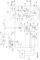
- FIG. 1 shows a representation of an agricultural vehicle 1, in the form of a tractor.
- the tractor 1 comprises a chassis 2, a cab 3, a front axle 4, and a rear axle 5 and is adapted to tow a range of different trailers.
- the tractor 1 has a brake system 10 which is connectable to a brake system on a trailer to control the trailer brakes.
- FIG. 2 illustrates a first embodiment of a brake system 10 in accordance with the invention installed on the tractor 1 and which comprises electronic control unit ECU 12.
- the brake system 10 includes a service brake system indicated generally at 200.
- the service brake system 200 includes a service brake circuit 221 with a brake master cylinder 210 operated by a brake pedal 212 depressed by the foot of an operator to generate a fluid pressure in the service brake circuit 221.
- the fluid pressure generated in the service brake circuit 221 is dependent on the pressure applied by the operator to brake pedal and is indicative of a brake demand by the operator. This fluid pressure will, therefore, be referred to as a Service Brake Demand Signal (SBDS).
- SBDS Service Brake Demand Signal
- references herein to a "brake demand” or “brake demand signal” in relation to a hydraulic line or circuit should be understood as referring to a pressure of the fluid in the line or circuit which is indicative of a required braking force.
- the hydraulic system of the trailer (not shown) is connected with the hydraulic system of the vehicle via standardized trailer couplings 420, 430. These include a supplementary trailer coupling 420 and a trailer brake control coupling 430.
- the supplementary trailer coupling 420 provides fluid supply to the trailer park brake system.
- the trailer brake control coupling 430 is provided to forward a trailer service brake demand signal TSBDS to the trailer brake system to provide a service brake functionality on the trailer.
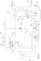
- the brake system 10' as shown in Figure 3 is substantially the same as that shown in Figure 2 and described above. Accordingly, only the differences between the brake system 10' in Figure 3 and that of Figure 2 will be described in detail.
- the service brake pilot line 515 is connected directly to an outlet port of the control valve 510 so that when the valve is activated and moved to its second position 510b, the service brake pilot line 515 is connected with the control system supply line 514 through the control valve 510, and hence is pressurised by the supply of pressurised hydraulic fluid from the pump 110.
- the control valve 510 has an additional outlet port through which the service brake pilot line 515 is connected to the hydraulic fluid tank 112 (ambient) via the control system return line 524 when the valve is in its first position 510a.
- the discharge valve is connected with the service brake pilot line 515.
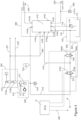
- FIG. 4 illustrates a further embodiment of a brake system 10" according to the invention.
- the trailer brake valve 410" has an additional service brake demand input port 410i.
- the trailer brake valve 410" is configured such that a service brake demand signal SBDS applied to either of the service brake demand ports 410e or 410i will generate a trailer service brake demand signal (fluid pressure) TSBDS which is forwarded to the trailer brake control coupling 430 through the trailer brake demand output port 410f.
- the service brake system 200 has two separate service brake circuits 221, 222, each operatively connected with a separate brake master cylinder 210a, 210b which are actuated from a single brake pedal 212. This provides for redundancy in case one of the circuits fails.
- the first service brake circuit 221 may be hydraulically connected to the brake actuators on the rear axle 5 while the second service brake circuit 222 is hydraulically connected to the brake actuators of the front axle 4.
- the other circuit 221, 222 can still be pressurised to provide braking capability.
- the assignment of the service brake circuits 221, 222 to respective vehicle wheels or axles may vary.
- an alternative configuration may have a diagonal assignment so that brakes on the front left wheel and rear right wheel may be actuated by a first service brake circuit 221 while those on the front right wheel and rear left wheel may be actuated by a second service brake circuit 222.
- the circuits may be arranged to actuate the brakes on opposite sides of the tractor, which may be required to provide a brake steering functionality.
- the fluid pressures in first and second service brake circuits 221, 222 represent service brake demand signals SBDS1, SBDS2 generated by the driver and which are forwarded to other components.
- the brake system 10 is arranged so that only one of the service brake circuits 221, 222 is connected to the trailer brake valve 410.
- the first service brake circuit 221 is connected through service brake demand input line 445 to a first one of the service brake demand input ports 410e, which receives the service brake demand signal SBDS1. This enables the service brake pilot line 515 to be connected to the other of the service brake demand input ports 410i without the need for a shuttle valve.
- the pilot trailer brake control system 500 as shown in Figure 4 does not have a piloted relay valve 512 but uses the control valve 510 itself to connect the service brake pilot line 515 and the service brake demand input port 410i to control system supply line 514 when the valve is actuated to move to its second position, in a manner similar to that discussed above in relation to Figure 3 .
- the brake system could be modified to use a piloted relay valve 512 if required.
- the electronic trailer brake control system 500 would be configured as shown in Figure 2 , except that the service brake pilot line 515 is connected to the second service brake demand input port 410i without the need for a shuttle valve.
- the brake system 10" of Figure 4 is reliant on one of the service brake circuits 221 to provide a SBDS to the trailer brake valve 410" to actuate the service brake function on the trailer during normal driving. Whilst this is perfectly acceptable, in the event the first service brake circuit 221 were to fail, no service brake demand would be forwarded to the trailer from the second service brake circuit.
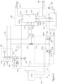
- each of the service brake circuits may be connected with a respective one of the service brake demand input ports 410e, 410i.
- the service brake pilot line 515 and one of the service brake circuits 222 are connected to one of the service brake demand input ports 410i through a shuttle valve 520 and a service brake demand input line 445a.
- Shuttle valve 520 provides a hydraulic OR functionality (i.e., logic control) to forward either the pressure in service brake circuit 222 or the pressure in service brake pilot line 515 (whichever is at the highest pressure) to the service brake demand input line 445a and to the service brake demand input port 410i of the trailer brake valve.
- the service brake pilot line 515 could alternatively be connected together with the first service brake circuit 221 to the other service brake demand input port 410e though a shuttle valve 520.
- the electronic trailer brake control system 500 as shown in Figure 5 does not have a piloted relay valve 512 but uses the control valve 510 to connect the service brake pilot line 515 and the service brake demand input port 410i to the control system supply line 514 and hence the pressurised hydraulic fluid from the pump 110 when the valve is activated.
- the brake system 10′′′ could be modified to use a piloted relay valve 512 if required.
- the brake system according to the invention and the embodiments described above provides electronic trailer braking function which can be easily incorporated into existing brake systems that currently only provide a fully hydraulic trailer brake control system.
Landscapes
- Engineering & Computer Science (AREA)
- Transportation (AREA)
- Mechanical Engineering (AREA)
- Physics & Mathematics (AREA)
- Fluid Mechanics (AREA)
- Electromagnetism (AREA)
- Regulating Braking Force (AREA)
Claims (16)
- Fahrzeugbremssystem (10; 10'; 10"; 10‴) mit:a) einer Quelle eines unter Druck stehenden Hyraulikfluids (100, 110);b) einem hydraulischen Betriebsbremssystem (200) mit mindestens einem Betriebsbremskreis (221, 222), der konfiguriert ist, um eine Betriebsbremsanforderung eines Benutzers weiterzugeben;c) einem Anhängerbremssteuersystem (400) für eine Verbindung mit einem Anhänger, der von dem Fahrzeug gezogen wird, wobei das Anhängerbremssteuersystem ein Anhängerbremsventil (410) aufweist, welches verfügt über:dadurch gekennzeichnet, dass das Bremssystem ein elektronisches Anhängerbremssteuersystem (500) aufweist mit einem Steuerventil (510), welches einer fluidischen Verbindung der Quelle des unter Druck stehenden Hydraulikfluids (100, 110) mit dem Bremsanforderungs-Eingangsanschluss dient, wobei das elektronische Anhängerbremssteuersystem während des Gebrauchs der selektiven Bereitstellung druckbeaufschlagten Hydraulikfluids dient, welches eine Bremsanforderung für den Anhänger indiziert, an dem Bremsanforderungs-Eingangsanschluss (410e, 410i).i) einen Bremsanforderungs-Eingangsanschluss (410e, 410i) für den Empfang eines Hydraulikdrucks, der eine Bremsanforderung indiziert; undii) einen Anhängerbremsanforderungs-Ausgangsanschluss (410f) für eine Verbindung mit einer Anhängerbremssteuerkupplung (430), wobei das Anhängerbremsventil konfiguriert ist zur Erzeugung eines Hydraulikfluid-Druckausgangs an dem Anhängerbremsanforderungs-Ausgangsanschluss, der abhängig ist von dem Hydraulikdruck, der an dem Bremsanforderungs-Eingangsanschluss wirkt;
- Fahrzeugbremssystem (10; 10'; 10"; 10‴) nach Anspruch 1, wobei das elektronische Anhängerbremssteuersystem (500) ein elektronisches Steuersystem aufweist mit einer elektronischen Steuereinheit (ECU 12), wobei die ECU konfiguriert ist, um im Gebrauch das elektronische Anhängerbremssteuersystem zu betätigen für eine Bereitstellung von unter Druck stehendem Hydraulikfluid, welches eine Bremsanforderung für den Anhänger indiziert, an dem Bremsanforderungs-Eingangsanschluss (410e, 410i) in Abhängigkeit davon, dass mindestens eine Betriebsbedingung des Fahrzeugs und/oder eines Anhängers, der von dem Fahrzeug gezogen wird, erfüllt ist, wobei die mindestens eine Betriebsbedingung des Fahrzeugs und/oder eines Anhängers, der von dem Fahrzeug gezogen wird, vorzugsweise indiziert, dass ein Schubzustand vorliegt.
- Fahrzeugbremssystem (10; 10'; 10"; 10‴) nach einem der vorhergehenden Ansprüche, wobei der Bremsanforderungs-Eingangsanschluss (410e, 410i) ein Betriebsbremsanforderungs-Eingangsanschluss ist, der betrieblich mit mindestens einem Betriebsbremskreis (221, 222) und einem Ausgang des elektronischen Anhängerbremssteuersystems mittels eines Wechselventils (520) verbindbar ist.
- Fahrzeugbremssystem (10; 10'; 10"; 10‴) nach einem der vorhergehenden Ansprüche, wobei das Steuerventil (510) betätigbar ist unter Steuerung durch das elektronische Steuersystem und bei Aktivierung betreibbar ist zur Herbeiführung, dass unter Druck stehendes Hydraulikfluid, welches eine Bremsanforderung für den Anhänger indiziert, weitergegeben wird an den Bremsanforderungs-Eingangsanschluss (410e, 410i).
- Fahrzeugbremssystem nach Anspruch 4, wobei das Steuerventil einen Einlass aufweist, der fluidisch mit der Quelle des unter Druck stehenden Hydraulikfluids und mit einem Fluid-Auslass verbunden ist, wobei das Steuerventil bewegbar ist zwischen einer nicht wirksamen Stellung, in der der Einlass und der Auslass voneinander getrennt sind, so dass Fluid nicht von dem Einlass durch den Auslass fließen kann, und mindestens einer wirksamen Betriebsstellung, in der der Einlass und der Auslass fluidisch verbunden sind und Fluid von dem Einlass durch den Auslass fließen kann, wobei der Auslass fluidisch mit dem Bremsanforderungs-Eingangsanschluss verbunden ist.
- Fahrzeugbremssystem (10) nach einem der Ansprüche 1 bis 4, wobei das elektronische Anhängerbremssteuersystem ein vorgesteuertes Ventil (512) aufweist, welches bei Betätigung zur Verbindung des Bremsanforderungs-Eingangsanschlusses (410e, 410i) mit der Quelle des unter Druck stehenden Hydraulikfluids (100, 110) dient, wobei die Betätigung des vorgesteuerten Ventils durch das Steuerventil gesteuert wird.
- Fahrzeugbremssystem (10; 10'; 10"; 10‴) nach Anspruch 6, wobei das Steuerventil (510) einen Einlass aufweist, der fluidisch mit der Quelle des unter Druck stehenden Hydraulikfluids (100, 110) und mit einem Fluidauslass verbunden ist, wobei das Steuerventil bewegbar ist zwischen einer nicht wirksamen Stellung (510a), in der der Einlass und der Auslass getrennt ist, so dass Fluid nicht von dem Einlass durch den Auslass fließen kann, und mindestens einer wirksamen Stellung (510b), in der der Einlass und der Auslass fluidisch verbunden sind und Fluid von dem Einlass durch den Auslass fließen kann, wobei der Auslass fluidisch mit einem Steueranschluss des vorgesteuerten Ventils verbunden ist.
- Fahrzeugbremssystem (10; 10'; 10"; 10‴) nach einem der vorhergehenden Ansprüche, wobei das elektronische Anhängerbremssteuersystem (500) konfiguriert ist zur Bereitstellung von Fluid an dem Bremsanforderungs-Eingangsanschluss (410e, 410i) mit mit einem Druck, der unter einem Maximaldruck des mindestens einen Betriebsbremskreises (221, 222) ist, und wobei vorzugsweise ein Druckbegrenzungsventil in der Leitung zwischen der Quelle des unter Druck stehenden Hydraulikfluids (11, 110) und dem Steuerventil (510) vorgesehen ist zur Begrenzung des Druckniveaus des Fluids durch das Steuerventil.
- Fahrzeugbremssystem (10; 10'; 10"; 10‴) nach einem der vorhergehenden Ansprüche, wobei das System einen Drucksensor (560) aufweist zur Überwachung des Drucks des Fluidausgangs des Anhängerbremsanforderungs-Ausgangsanschlusses (410f), wobei das elektronische Steuersystem konfiguriert ist für eine Steuerung des Betriebs des elektronischen Anhängerbremssteuersystems (500) in Abhängigkeit von einem Ausgang des Drucksensors, um den Druck des Hydraulikfluids, welches an dem Bremsanforderungs-Eingangsanschluss (410e, 410i) bereitgestellt wird, bei einem vorbestimmten Niveau zu halten.
- Fahrzeugbremssystem (10; 10'; 10"; 10‴) nach einem der vorhergehenden Ansprüche, wobei das Steuerventil (510) ein Proportionalventil ist.
- Fahrzeugbremssystem (10; 10'; 10"; 10‴) nach Anspruch 5, wobei ein Druckentlastungsventil (540) in einer Fluidleitung zwischen dem Steuerventil (510) und dem Bremsanforderungs-Eingangsanschluss angeordnet ist, wobei das Entlastungsventil in einer ersten Stellung (540a) den Druck in der Fluidleitung reduziert.
- Fahrzeugbremssystem (10; 10'; 10"; 10‴) nach Anspruch 6, wobei ein Druckentlastunsventil (540) in einer Fluidleitung zwischen dem Steuerventil (510) und dem vorgesteuerten Ventil (512) angeordnet ist, wobei das Entlastungsventil in einer ersten Stellung (540a) den Druck in der Fluidleitung reduziert.
- Fahrzeugbremssystem (10"') nach einem der vorhergehenden Ansprüche, wobei das Betriebsbremssystem einen ersten Betriebsbremskreis (221) und einen zweiten Betriebsbremskreis (222) aufweist, wobei jeder Betriebsbremskreis der Weitergabe eines Fluiddrucks dient, der eine Betriebsbremsanforderung eines Benutzers indiziert, wobei das Anhängerbremsventil (410) einen ersten Betriebsbremsanforderungs-Einlassanschluss (410e) und einen zweiten Betriebsbremsanforderungs-Eingangsanschluss (410i) aufweist, der Druckausgang an dem Anhängerbremsanforderungs-Ausgangsanschluss (410f) abhängt von dem Druck, der an dem ersten Betriebsbremsanforderungs-Eingangsanschluss wirkt, und/oder abhängt von dem Druck, der an dem zweiten Betriebsbremsanforderungs-Eingangsanschluss wirkt, wobei der erste oder zweite Betriebsbremsanforderungs-Anschluss (410i) den Bremsanforderungs-Eingangsanschluss bildet und dieser über ein Wechselventils (520) mit dem zugeordneten Betriebsbremskreis (222) und einem Ausgang des elektronischen Anhängerbremssteuersystems betrieblich verbunden ist.
- Fahrzeugbremssystem (10") nach einem der Ansprüche 1 bis 12, wobei das Betriebsbremssystem (200) einen ersten Betriebsbremskreis (221) und einen zweiten Betriebsbremskreis (222) aufweist, jeder Betriebsbremskreis der Weitergabe von Fluiddruck dient, der eine Betriebsbremsanforderung eines Benutzers indiziert, wobei das Anhängerbremsventil (410) einen ersten Betriebsbremsanforderungs-Eingangsanschluss (410e) und einen zweiten Betriebsbremsanforderungs-Eingangsanschluss (410i) aufweist, der Druckausgang des Anhängerbremsanforderungs-Ausgangsanschlusses (410f) abhängt von dem Druck, der an dem ersten Betriebsbremsanforderungs-Eingangsanschluss wirkt, und/oder abhängt von dem Druck, der an dem zweiten Betriebsbremsanforderungs-Eingangsanschluss wirkt, wobei der erste oder zweite Betriebsbremskreis (221) mit dem ersten oder zweiten Betriebsanforderungs-Eingangsanschluss (410e) verbunden ist und der andere von dem ersten und zweiten Bremsanforderungs-Eingangsanschluss (410f) mit einem Ausgang des elektronischen Anhängerbremssteuersystems (500) verbunden ist.
- Fahrzeugbremssystem (10; 10'; 10"; 10‴) nach einem der Ansprüche 1 bis 14, wobei das elektronische Anhängerbremssteuersystem (500) mit der Quelle des unter Druck stehenden Hydraulikfluids (100, 110) über das Anhängerbremsventil (410) verbunden ist.
- Landwirtschaftliches Fahrzeug (1) mit einem Fahrzeugbremssystem (10; 10'; 10"; 10‴) nach einem der vorhergehenden Ansprüche.
Applications Claiming Priority (2)
| Application Number | Priority Date | Filing Date | Title |
|---|---|---|---|
| GBGB2019737.2A GB202019737D0 (en) | 2020-12-15 | 2020-12-15 | Trailer brake control system |
| PCT/IB2021/061029 WO2022130077A1 (en) | 2020-12-15 | 2021-11-27 | Trailer brake control system |
Publications (2)
| Publication Number | Publication Date |
|---|---|
| EP4263301A1 EP4263301A1 (de) | 2023-10-25 |
| EP4263301B1 true EP4263301B1 (de) | 2025-07-09 |
Family
ID=74188763
Family Applications (1)
| Application Number | Title | Priority Date | Filing Date |
|---|---|---|---|
| EP21819591.5A Active EP4263301B1 (de) | 2020-12-15 | 2021-11-27 | Anhängerbremssteuersystem |
Country Status (4)
| Country | Link |
|---|---|
| US (1) | US20240092329A1 (de) |
| EP (1) | EP4263301B1 (de) |
| GB (1) | GB202019737D0 (de) |
| WO (1) | WO2022130077A1 (de) |
Families Citing this family (3)
| Publication number | Priority date | Publication date | Assignee | Title |
|---|---|---|---|---|
| GB2620183B (en) * | 2022-06-30 | 2024-10-09 | Bamford Excavators Ltd | A method and system for enhanced braking in a tractor unit |
| IT202300010221A1 (it) * | 2023-05-19 | 2024-11-19 | Cnh Ind Italia Spa | Sistema di frenatura ad azionamento idraulico migliorato per un veicolo da lavoro |
| IT202300020496A1 (it) * | 2023-10-04 | 2025-04-04 | Cnh Ind Italia Spa | Disposizione idraulica migliorata per un sistema trattore-rimorchio |
Citations (1)
| Publication number | Priority date | Publication date | Assignee | Title |
|---|---|---|---|---|
| EP2729334B1 (de) * | 2011-07-04 | 2018-05-02 | CNH Industrial Italia S.p.A. | Verfahren und vorrichtung zum bremsen einer traktor-anhänger-kombination |
Family Cites Families (11)
| Publication number | Priority date | Publication date | Assignee | Title |
|---|---|---|---|---|
| DE20315755U1 (de) * | 2003-10-09 | 2003-12-18 | Krenner, Josef | Bremsanlage |
| DE102009031851B4 (de) | 2009-07-03 | 2021-02-11 | Dipl. Ing. Tietjen Gmbh | Verfahren zur Abbremsung einer Zugfahrzeug-Anhänger-Kombination und Einrichtung |
| ITMO20120323A1 (it) * | 2012-12-21 | 2014-06-22 | Cnh Italia Spa | Apparato di controllo per controllare un freno di una unità trainata da un veicolo. |
| ITMO20120320A1 (it) * | 2012-12-21 | 2014-06-21 | Cnh Italia Spa | Metodo ed apparato per controllare la frenatura di una combinazione trattore rimorchio. |
| DE102014002614A1 (de) * | 2014-02-27 | 2015-08-27 | Wabco Gmbh | Bremsmodul für ein hydraulisch gebremstes Zugfahrzeug, welches mit einem pneumatisch gebremsten Anhängefahrzeug koppelbar ist. |
| WO2017076435A1 (en) * | 2015-11-03 | 2017-05-11 | Volvo Truck Corporation | A control system and method for an articulated vehicle comprising an autonomous emergency braking system |
| DE102016104453A1 (de) | 2016-03-11 | 2017-09-14 | Claas Tractor Sas | Landwirtschaftlicher Zug mit einem Zugfahrzeug und Anhänger |
| US10173652B2 (en) * | 2016-07-28 | 2019-01-08 | Deere & Company | Hydraulic trailer brake circuit for adjustable gain and improved stability |
| IT201700052010A1 (it) * | 2017-05-12 | 2018-11-12 | Safim S P A | Dispositivo di controllo di una valvola freno-rimorchio, collegabile all’impianto di frenatura di un rimorchio, per veicoli di traino con trasmissione idrostatica provvista di almeno una pompa a cilindrata variabile |
| IT201700089945A1 (it) * | 2017-08-03 | 2019-02-03 | Cnh Ind Italia Spa | Circuito di controllo freni del rimorchio di un trattore |
| DE102019002497A1 (de) * | 2019-04-05 | 2020-10-08 | Suffel Fördertechnik GmbH & Co. KG | Vorrichtung zum Beschleunigen und Verfahren zum Beschleunigen |
-
2020
- 2020-12-15 GB GBGB2019737.2A patent/GB202019737D0/en not_active Ceased
-
2021
- 2021-11-27 US US18/253,967 patent/US20240092329A1/en active Pending
- 2021-11-27 WO PCT/IB2021/061029 patent/WO2022130077A1/en not_active Ceased
- 2021-11-27 EP EP21819591.5A patent/EP4263301B1/de active Active
Patent Citations (1)
| Publication number | Priority date | Publication date | Assignee | Title |
|---|---|---|---|---|
| EP2729334B1 (de) * | 2011-07-04 | 2018-05-02 | CNH Industrial Italia S.p.A. | Verfahren und vorrichtung zum bremsen einer traktor-anhänger-kombination |
Also Published As
| Publication number | Publication date |
|---|---|
| US20240092329A1 (en) | 2024-03-21 |
| EP4263301A1 (de) | 2023-10-25 |
| WO2022130077A1 (en) | 2022-06-23 |
| GB202019737D0 (en) | 2021-01-27 |
Similar Documents
| Publication | Publication Date | Title |
|---|---|---|
| EP4263301B1 (de) | Anhängerbremssteuersystem | |
| US6059383A (en) | Braking control system for agricultural tractors | |
| US9022487B2 (en) | System and method for brake assisted turning | |
| US4708406A (en) | Hydraulic braking system with malfunction alarm junction | |
| US8616659B2 (en) | Vehicle steering and braking system | |
| EP3275747B1 (de) | Pneumatische anhängerbremsenschaltung mit losbrecherkennung und verfahren dafür | |
| US20070205656A1 (en) | Hydraulic Braking Arrangement For A Trailer | |
| EP3284643B1 (de) | Kreislauf einer hydraulischen anhängerbremse zur verstellbaren verstärkung und verbesserten stabilität | |
| GB2492124A (en) | Vehicle braking system having an electrically operable emergency braking override valve | |
| EP2337721B1 (de) | Ackerschlepper | |
| GB2509806B (en) | Electrohydraulic antilock brake system with isolation valve | |
| US5005130A (en) | Trailer swing control | |
| GB2490925A (en) | Vehicle braking system | |
| EP4263303B1 (de) | Anhängerbremssteuerungssystem | |
| CS322091A3 (en) | Fluid-pressure brake system with electrically-controlled valves | |
| EP4077074B1 (de) | Anhängerbremssteuersystem | |
| CN115626150A (zh) | 矿用车制动防抱死控制系统及其控制方法 | |
| US11724676B2 (en) | Trailer detection and control module | |
| GB2599889A (en) | A vehicle braking system | |
| US12454258B2 (en) | Trailer control valve of a towing vehicle |
Legal Events
| Date | Code | Title | Description |
|---|---|---|---|
| STAA | Information on the status of an ep patent application or granted ep patent |
Free format text: STATUS: UNKNOWN |
|
| STAA | Information on the status of an ep patent application or granted ep patent |
Free format text: STATUS: THE INTERNATIONAL PUBLICATION HAS BEEN MADE |
|
| PUAI | Public reference made under article 153(3) epc to a published international application that has entered the european phase |
Free format text: ORIGINAL CODE: 0009012 |
|
| STAA | Information on the status of an ep patent application or granted ep patent |
Free format text: STATUS: REQUEST FOR EXAMINATION WAS MADE |
|
| 17P | Request for examination filed |
Effective date: 20230717 |
|
| AK | Designated contracting states |
Kind code of ref document: A1 Designated state(s): AL AT BE BG CH CY CZ DE DK EE ES FI FR GB GR HR HU IE IS IT LI LT LU LV MC MK MT NL NO PL PT RO RS SE SI SK SM TR |
|
| DAV | Request for validation of the european patent (deleted) | ||
| DAX | Request for extension of the european patent (deleted) | ||
| GRAP | Despatch of communication of intention to grant a patent |
Free format text: ORIGINAL CODE: EPIDOSNIGR1 |
|
| STAA | Information on the status of an ep patent application or granted ep patent |
Free format text: STATUS: GRANT OF PATENT IS INTENDED |
|
| INTG | Intention to grant announced |
Effective date: 20250213 |
|
| GRAS | Grant fee paid |
Free format text: ORIGINAL CODE: EPIDOSNIGR3 |
|
| GRAA | (expected) grant |
Free format text: ORIGINAL CODE: 0009210 |
|
| STAA | Information on the status of an ep patent application or granted ep patent |
Free format text: STATUS: THE PATENT HAS BEEN GRANTED |
|
| AK | Designated contracting states |
Kind code of ref document: B1 Designated state(s): AL AT BE BG CH CY CZ DE DK EE ES FI FR GB GR HR HU IE IS IT LI LT LU LV MC MK MT NL NO PL PT RO RS SE SI SK SM TR |
|
| REG | Reference to a national code |
Ref country code: GB Ref legal event code: FG4D |
|
| REG | Reference to a national code |
Ref country code: CH Ref legal event code: EP |
|
| REG | Reference to a national code |
Ref country code: IE Ref legal event code: FG4D |
|
| REG | Reference to a national code |
Ref country code: DE Ref legal event code: R096 Ref document number: 602021033917 Country of ref document: DE |
|
| REG | Reference to a national code |
Ref country code: NL Ref legal event code: MP Effective date: 20250709 |