EP2750949B1 - Fahrzeugbremssystem - Google Patents
Fahrzeugbremssystem Download PDFInfo
- Publication number
- EP2750949B1 EP2750949B1 EP12712350.3A EP12712350A EP2750949B1 EP 2750949 B1 EP2750949 B1 EP 2750949B1 EP 12712350 A EP12712350 A EP 12712350A EP 2750949 B1 EP2750949 B1 EP 2750949B1
- Authority
- EP
- European Patent Office
- Prior art keywords
- valve
- port
- brake
- emergency
- supply
- Prior art date
- Legal status (The legal status is an assumption and is not a legal conclusion. Google has not performed a legal analysis and makes no representation as to the accuracy of the status listed.)
- Active
Links
- 239000012530 fluid Substances 0.000 claims description 92
- 238000011144 upstream manufacturing Methods 0.000 claims description 5
- 230000009471 action Effects 0.000 claims description 4
- 230000000694 effects Effects 0.000 description 4
- 230000004044 response Effects 0.000 description 3
- 230000008901 benefit Effects 0.000 description 2
- 238000000034 method Methods 0.000 description 2
- 238000013022 venting Methods 0.000 description 2
- 230000000712 assembly Effects 0.000 description 1
- 238000000429 assembly Methods 0.000 description 1
- 244000145845 chattering Species 0.000 description 1
- 238000013329 compounding Methods 0.000 description 1
- 230000006872 improvement Effects 0.000 description 1
- 230000003472 neutralizing effect Effects 0.000 description 1
- 230000009467 reduction Effects 0.000 description 1
- 230000001629 suppression Effects 0.000 description 1
- 230000000007 visual effect Effects 0.000 description 1
Images


Classifications
-
- B—PERFORMING OPERATIONS; TRANSPORTING
- B60—VEHICLES IN GENERAL
- B60T—VEHICLE BRAKE CONTROL SYSTEMS OR PARTS THEREOF; BRAKE CONTROL SYSTEMS OR PARTS THEREOF, IN GENERAL; ARRANGEMENT OF BRAKING ELEMENTS ON VEHICLES IN GENERAL; PORTABLE DEVICES FOR PREVENTING UNWANTED MOVEMENT OF VEHICLES; VEHICLE MODIFICATIONS TO FACILITATE COOLING OF BRAKES
- B60T17/00—Component parts, details, or accessories of power brake systems not covered by groups B60T8/00, B60T13/00 or B60T15/00, or presenting other characteristic features
- B60T17/18—Safety devices; Monitoring
- B60T17/22—Devices for monitoring or checking brake systems; Signal devices
- B60T17/226—Devices for monitoring or checking brake systems; Signal devices using devices being responsive to the difference between the fluid pressions in conduits of multiple braking systems
- B60T17/227—With additional functions, e.g. by-pass
-
- B—PERFORMING OPERATIONS; TRANSPORTING
- B60—VEHICLES IN GENERAL
- B60T—VEHICLE BRAKE CONTROL SYSTEMS OR PARTS THEREOF; BRAKE CONTROL SYSTEMS OR PARTS THEREOF, IN GENERAL; ARRANGEMENT OF BRAKING ELEMENTS ON VEHICLES IN GENERAL; PORTABLE DEVICES FOR PREVENTING UNWANTED MOVEMENT OF VEHICLES; VEHICLE MODIFICATIONS TO FACILITATE COOLING OF BRAKES
- B60T13/00—Transmitting braking action from initiating means to ultimate brake actuator with power assistance or drive; Brake systems incorporating such transmitting means, e.g. air-pressure brake systems
- B60T13/10—Transmitting braking action from initiating means to ultimate brake actuator with power assistance or drive; Brake systems incorporating such transmitting means, e.g. air-pressure brake systems with fluid assistance, drive, or release
- B60T13/24—Transmitting braking action from initiating means to ultimate brake actuator with power assistance or drive; Brake systems incorporating such transmitting means, e.g. air-pressure brake systems with fluid assistance, drive, or release the fluid being gaseous
- B60T13/26—Compressed-air systems
- B60T13/261—Compressed-air systems systems with both indirect application and application by springs or weights and released by compressed air
- B60T13/265—Compressed-air systems systems with both indirect application and application by springs or weights and released by compressed air dependent systems, e.g. trailer systems
-
- B—PERFORMING OPERATIONS; TRANSPORTING
- B60—VEHICLES IN GENERAL
- B60T—VEHICLE BRAKE CONTROL SYSTEMS OR PARTS THEREOF; BRAKE CONTROL SYSTEMS OR PARTS THEREOF, IN GENERAL; ARRANGEMENT OF BRAKING ELEMENTS ON VEHICLES IN GENERAL; PORTABLE DEVICES FOR PREVENTING UNWANTED MOVEMENT OF VEHICLES; VEHICLE MODIFICATIONS TO FACILITATE COOLING OF BRAKES
- B60T13/00—Transmitting braking action from initiating means to ultimate brake actuator with power assistance or drive; Brake systems incorporating such transmitting means, e.g. air-pressure brake systems
- B60T13/10—Transmitting braking action from initiating means to ultimate brake actuator with power assistance or drive; Brake systems incorporating such transmitting means, e.g. air-pressure brake systems with fluid assistance, drive, or release
- B60T13/66—Electrical control in fluid-pressure brake systems
- B60T13/68—Electrical control in fluid-pressure brake systems by electrically-controlled valves
- B60T13/686—Electrical control in fluid-pressure brake systems by electrically-controlled valves in hydraulic systems or parts thereof
-
- B—PERFORMING OPERATIONS; TRANSPORTING
- B60—VEHICLES IN GENERAL
- B60T—VEHICLE BRAKE CONTROL SYSTEMS OR PARTS THEREOF; BRAKE CONTROL SYSTEMS OR PARTS THEREOF, IN GENERAL; ARRANGEMENT OF BRAKING ELEMENTS ON VEHICLES IN GENERAL; PORTABLE DEVICES FOR PREVENTING UNWANTED MOVEMENT OF VEHICLES; VEHICLE MODIFICATIONS TO FACILITATE COOLING OF BRAKES
- B60T17/00—Component parts, details, or accessories of power brake systems not covered by groups B60T8/00, B60T13/00 or B60T15/00, or presenting other characteristic features
- B60T17/18—Safety devices; Monitoring
- B60T17/22—Devices for monitoring or checking brake systems; Signal devices
- B60T17/221—Procedure or apparatus for checking or keeping in a correct functioning condition of brake systems
-
- B—PERFORMING OPERATIONS; TRANSPORTING
- B60—VEHICLES IN GENERAL
- B60T—VEHICLE BRAKE CONTROL SYSTEMS OR PARTS THEREOF; BRAKE CONTROL SYSTEMS OR PARTS THEREOF, IN GENERAL; ARRANGEMENT OF BRAKING ELEMENTS ON VEHICLES IN GENERAL; PORTABLE DEVICES FOR PREVENTING UNWANTED MOVEMENT OF VEHICLES; VEHICLE MODIFICATIONS TO FACILITATE COOLING OF BRAKES
- B60T8/00—Arrangements for adjusting wheel-braking force to meet varying vehicular or ground-surface conditions, e.g. limiting or varying distribution of braking force
- B60T8/17—Using electrical or electronic regulation means to control braking
- B60T8/1701—Braking or traction control means specially adapted for particular types of vehicles
- B60T8/1708—Braking or traction control means specially adapted for particular types of vehicles for lorries or tractor-trailer combinations
-
- B—PERFORMING OPERATIONS; TRANSPORTING
- B60—VEHICLES IN GENERAL
- B60T—VEHICLE BRAKE CONTROL SYSTEMS OR PARTS THEREOF; BRAKE CONTROL SYSTEMS OR PARTS THEREOF, IN GENERAL; ARRANGEMENT OF BRAKING ELEMENTS ON VEHICLES IN GENERAL; PORTABLE DEVICES FOR PREVENTING UNWANTED MOVEMENT OF VEHICLES; VEHICLE MODIFICATIONS TO FACILITATE COOLING OF BRAKES
- B60T8/00—Arrangements for adjusting wheel-braking force to meet varying vehicular or ground-surface conditions, e.g. limiting or varying distribution of braking force
- B60T8/32—Arrangements for adjusting wheel-braking force to meet varying vehicular or ground-surface conditions, e.g. limiting or varying distribution of braking force responsive to a speed condition, e.g. acceleration or deceleration
- B60T8/321—Arrangements for adjusting wheel-braking force to meet varying vehicular or ground-surface conditions, e.g. limiting or varying distribution of braking force responsive to a speed condition, e.g. acceleration or deceleration deceleration
- B60T8/323—Systems specially adapted for tractor-trailer combinations
Definitions
- the present invention relates to a braking system according to the preamble of claim 1, particularly, but not exclusively to a braking system for a trailer of a road vehicle comprising a tractor and trailer combination.
- a braking system of this kind is known from WO 2011/003491 A .
- a service actuator in which air pressure on a piston or diaphragm pushes a rod which applies mechanical turning force to the input shaft of the brake
- a service/spring actuator which includes, in addition to a service actuator, a spring actuator comprising an internal coil spring which acts on the pushrod, which can be compressed when a second chamber is pressurised.
- the brakes can be applied therefore by either increasing pressure supplied to the service actuator as normal, and/or by a reducing the pressure supplied to the spring actuator.
- a common configuration for example, is a semi-trailer with three axles, the front of which has service actuators and the middle and rear of which has service/spring actuators. Other combinations are possible, however.
- an emergency apply function acts when the pneumatic supply line ('red line') to the trailer is disconnected, exhausted or severed (thereby preventing the trailer reservoir from being replenished with compressed air).
- the emergency apply function acts on either the service actuators or the spring actuators, and can be required due to a fault when the vehicle is moving.
- a shunt valve is also included to divert air from the trailer reservoir to defeat the emergency apply function in order to allow the trailer to be moved ('shunted') without connection to a towing vehicle with a compressed air supply. This may be required, for instance, at a distribution depot or ferry terminal.
- Emergency braking by the supply of pressurised fluid to the service actuators has an advantage in that this flow of fluid is normally controlled by the electronic braking system (EBS) or anti-lock braking system (ABS) of the trailer.
- EBS electronic braking system
- ABS anti-lock braking system
- the vehicle can either be immediately brought to a safe stop with the benefit of the anti-lock function, or the emergency brake application can be held off whilst the driver is warned of the situation. The driver may then bring the vehicle to a safe stop at the side of the road using normal service braking.
- the braking system is provided with a means for preventing the emergency application of the spring brake in the event of loss of pressure in the spring brake circuit, and the service braking circuit downstream of the or each modulator associated with brake actuators on one side of the vehicle is connected to the spring brake line via a shuttle valve.
- the shuttle valve is configured such that pressurised fluid is supplied to the spring brake line from this portion of the service braking circuit when the fluid pressure in the spring brake line is lower than the pressure in the service brake circuit.
- fluid from one half of the service braking circuit is used to prevent the application of the spring brake.
- the service braking circuit may then be used to apply the brakes to bring the vehicle to a halt.
- the ABS is disabled on the one side of the vehicle, however, to avoid chattering of the spring brake during an ABS intervention, but can be operated as normal on the other side of the vehicle.
- a further alternative proposal, disclosed in WO2011/003491 is alleged to be an improvement over the system disclosed in EP1538054 .
- the system acts to direct pressurised fluid from the service circuit to the spring brake circuit to release the spring brakes, whilst at the same time applying the service brakes.
- a "spring store neutralising valve” is operated to isolate the spring brake chambers.
- the EBS modulator may then use conventional ABS algorithms to modify the braking force applied by the service brakes on both sides of the vehicle without affecting the spring brake.
- a vehicle braking system comprising a brake actuator which is operable to adopt a brake apply position in which the actuator may apply a braking force to a vehicle wheel and a brake release position in which the actuator may release any braking force applied to a vehicle wheel
- the brake actuator having a spring brake chamber and a spring and being configured such that supply of pressurised fluid to the spring brake chamber causes the brake actuator to move against the biasing force of the spring to the brake release position and release of pressurised fluid from the spring brake chamber causes the brake actuator to move under the action of the spring to the brake apply position
- the system further including a supply line whereby the spring brake chamber is, in use, connected to a supply of pressurised fluid, and an emergency brake apply valve which has a control port which is connected to the supply line, the emergency brake apply valve being configured automatically to connect the spring brake chamber to a low pressure region when the pressure at the control port falls below a predetermined level
- the system further includes an electrically operable emergency braking override valve which
- the emergency brake apply valve has an input port which is connected to the supply line and a second port which is connected to the spring brake chamber, and is movable between a first position in which the input port is connected to the output port and a second position in which the input port is closed and the output port vents to a low pressure region.
- mechanical biasing means may be provided to urge the emergency brake apply valve into the second position, and movement of the emergency brake apply valve from the second position to the first position is achieved by the supply of pressurised fluid to the control input at sufficient pressure to overcome the force of the biasing means.
- the brake actuator may further include a service brake chamber, wherein supply of pressurised fluid to the service brake chamber causes the brake actuator to move to the brake apply position.
- the system may further include a control line which in use connects a source of a fluid pressure braking demand signal to the service brake chamber via a braking control valve assembly.
- the brake valve assembly may comprise at least one modulator which has a control port which is connected to the control line for receipt of a fluid pressure braking demand signal, a supply port which is connected to a source of pressurised fluid, a delivery port which is connected to the service brake chamber, and an exhaust port which vents to a low pressure region, the modulator being operable to move between a build configuration in which the supply port is connected to the delivery port whilst the exhaust port is closed, a hold configuration in which the exhaust port and the supply ports are closed and an exhaust configuration in which the delivery port is connected to the exhaust port whilst the supply port is closed.
- the vehicle braking system further comprises a pressurised fluid reservoir which is connected to the control line via a brake apply valve.
- the brake apply valve may be movable between a first configuration in which the brake apply valve substantially prevents flow of fluid from the pressurised fluid reservoir to the control line, and a second in which the brake apply valve allows flow of fluid from the pressurised fluid reservoir to the control line.
- a non-return valve may be provided in the supply line upstream of the input port of the emergency brake apply valve, the non-return valve permitting flow of fluid along the supply line to the emergency brake apply valve whilst substantially preventing flow of fluid in the opposite direction.
- the pressurised fluid reservoir may be connected to the supply line downstream of the non-return valve.
- a second non-return valve may be provided in the supply line upstream of the input port of the emergency brake apply valve, the second non-return valve also permitting flow of fluid along the supply line to the emergency brake apply valve whilst substantially preventing flow of fluid in the opposite direction.
- the pressurised fluid reservoir may be connected to the supply line between the two non-return valves.
- the emergency braking override valve has a third port which is connected to the supply line between the first port of the emergency brake apply valve and the connection to the control port of the emergency brake apply valve.
- the third port may be connected to the supply line downstream of the non-return valve. Where two non-return valves are provided, the third port is preferably connected to the supply line between the two non-return valves.
- the emergency braking override valve may be movable between a first position in which its first port is connected to its second port, whilst its third port is closed, and a second position in which its third port is connected to its second port whilst its first port is closed.
- the emergency braking override valve may be provided with mechanical biasing means to urge the emergency braking override valve into the first position, movement of the emergency braking override valve from the first position to the second position being achieved by the supply of electrical power to the emergency braking override valve.
- the emergency braking override valve is movable between a first position in which its first port is connected to its second port, and a second position in which flow of fluid between its second port and its first port is substantially prevented.
- the emergency braking override valve is preferably provided with mechanical biasing means to urge the emergency braking override valve into its first position, and movement of the emergency braking override valve from the first position to the second position being achieved by the supply of an electrical current to the emergency braking override valve.
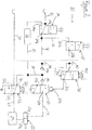
- a braking system 10 for a trailer of a vehicle comprising a tractor and a trailer or semi-trailer.
- the braking system comprises a supply line 12 which is adapted to be connected to a source of pressurised fluid, typically compressed air, on a tractor to which the trailer is coupled.
- the supply line 12 extends first input 14a of a shunt valve 14, the output 14b of the shunt valve 14 being connected to a junction between an emergency apply line 16 and a park line 18.
- the emergency apply line 16 extends to an input 20a of an emergency apply valve 20, whilst the park line 16 extends to an input 22a of a park valve 22.
- the output 20b of the emergency apply valve 20 is connected to the spring brake chamber 23a of a service / spring actuator 23 via a spring brake line 21.
- the emergency apply valve 20 is also provided with a control input 20c which is connected to an output 22b of the park valve 22.
- Two one-way check valves 24a, 24b are provided in the emergency apply line 16, both being oriented to allow flow of fluid from the shunt valve 14 to the emergency apply valve 20 but to prevent flow of fluid in the other direction along the emergency apply line 16, i.e. away from the emergency apply valve 20.
- a trailer reservoir supply line 26 extends from the emergency apply line 16 between the two check valves 24a, 24b to a pressurised fluid reservoir 28 mounted on the trailer.
- An outlet from the trailer reservoir 28 is connected to a second input 14c of the shunt valve 14.
- control line 30 which is adapted to be coupled to a braking control line on a tractor to which the trailer is coupled, the braking control line carrying a fluid pressure braking demand signal generated when a driver of the vehicle operates a brake pedal or the like to indicate a need for braking.
- the control line 30 is connected to a first input 32a of a brake apply valve 32, an output 32b of the brake apply valve 32 being connected to control input of a conventional electrical braking system (EBS) control valve assembly 25 via a service brake line 27.
- EBS control valve assembly 25 typically comprises at least a modulator and is connected to the service brake chamber 23b of a brake actuator 23.
- the modulator has a control port which is connected to the control line for receipt of a fluid pressure braking demand signal, a supply port which is connected to a source of pressurised fluid, a delivery port which is connected to the service brake chamber, and an exhaust port which vents to a low pressure region, and is operable to move between a build configuration in which the supply port is connected to the delivery port whilst the exhaust port is closed, a hold configuration in which the exhaust port and the supply ports are closed and an exhaust configuration in which the delivery port is connected to the exhaust port whilst the supply port is closed.
- the EBS control valve assembly 25 is operable to provide anti-lock braking control.
- a second input 32c of the brake apply valve 32 is connected to the trailer reservoir supply line 26.
- the system is also provided with an emergency braking override valve36 which has a first port 36a which is connected to the output 22b of the park valve 22, a second port 36b which is connected to the control input 20c of the emergency apply valve 20, and a third port 36c which is connected to the emergency apply line 16 between the first and second one-way check valves 24a, 24b.
- an emergency braking override valve36 which has a first port 36a which is connected to the output 22b of the park valve 22, a second port 36b which is connected to the control input 20c of the emergency apply valve 20, and a third port 36c which is connected to the emergency apply line 16 between the first and second one-way check valves 24a, 24b.
- the shunt valve 14 is movable between a first position (illustrated in Figure 1 ) in which the first input 14a is connected to the output 14b whilst the second input 14c is closed, and a second position in which the first input 14a is closed and the second input 14c is connected to the output 14b.
- the shunt valve 14 is adapted to be moved manually between the first and second positions.
- the emergency apply valve 20 is movable between a first position (illustrated in Figure 1 ) in which the first input 20a is connected to the output 20b and a second position in which the first input 20a is closed and the output 20b vents to a low pressure region (typically to atmosphere).
- Mechanical biasing means in this example a spring is provided to urge the emergency apply valve 20 into the second position. Movement of the emergency apply valve 20 from the second position to the first position is achieved by the supply of pressurised fluid to the control input 20c at sufficient pressure to overcome the force of the biasing means.
- the park valve 22 is movable between a first position (illustrated in Figure 1 ) in which the input 22a is connected to the output 22b and a second position in which the input 22a is closed and the output 22b vents to a low pressure region (typically to atmosphere).
- the park valve 22 is adapted to be moved manually between the first and second positions.
- the brake apply valve 32 is movable between a first position (illustrated in Figure 1 ) in which the first input 32a is connected to the output 32b, whilst the second input 32c is closed, and a second position in which the first input 32a is closed and the third input 32c is connected to the output 32b.
- the brake apply valve 32 is electrically operable, in this example, by means of a solenoid.
- Mechanical biasing means in this example a spring
- Movement of the brake apply valve 32 from the first position to the second position is achieved by the supply of an electrical current to the solenoid 32d.
- the emergency braking override valve 36 is movable between a first position (illustrated in Figures 1 to 5 ) in which its first port 36a is connected to its second port 36b, whilst its third port 36c is closed, and a second position (illustrated in Figure 6 ) in which its third port 36c is connected to its second port 36b whilst its first port 36a is closed.
- the passage of fluid from the supply line 16 to the control input 20c of the emergency apply valve 20 via the park valve 22 is therefore not affected by the emergency braking override valve36 when the emergency braking override valve 36 is in its first portion.
- the emergency braking override valve 36 is electrically operable, in this example, by means of a solenoid 36d.
- Mechanical biasing means (in this example a spring) is provided to urge the emergency braking override valve 36 into the first position. Movement of the emergency braking override valve 36 from the first position to the second position is achieved by the supply of an electrical current to the solenoid 36d.
- the braking system is operated as follows.
- the braking system When the trailer is coupled to a tractor, and there is normal service braking, the braking system is configured as shown in Figure 1 .
- the shunt valve 14 and park valve 22 are set to their first positions, and there is no supply of electrical current to the brake apply valve 32.
- the supply line 12 is connected to a source of pressurised fluid on the tractor, and pressurised fluid passes to the control input 20c of the emergency apply valve 20 via the park line 18 and the park valve 22.
- pressurised fluid at its control input 20a causes the emergency apply valve 20 to move to its first position whereby the first input 20a is connected to the output 20b.
- pressurised fluid passes along the emergency apply line 16 via the shunt valve 14, and then to the spring brake chamber 32a of the brake actuator 32b via the emergency apply valve 20 and spring brake line 21.
- the fluid pressure in the spring brake chamber 32a overcomes the biasing force of the spring and the actuator acts to release the brake.
- Pressurised fluid also passes from the tractor to the trailer reservoir 28 via the trailer reservoir supply line 26 so that the trailer reservoir 28 is charged with pressurised fluid.
- a conventional anti-lock function may be provided by means of modulating valves in the EBS valve assembly 25.
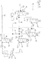
- the system 10 may be operated to provide service braking even when there is no fluid pressure braking demand signal by the supply of an electrical current to the solenoid 32d of the brake apply valve 32.
- This causes the brake apply valve 32 to move to its second position in which the first input 32a is closed and the second input 32c is connected to the output 32b, as illustrated in Figure 2 .
- Pressurised fluid then passes from the supply line 12 through the shunt valve 14 to the emergency apply line 16, through the first one way check valve 24a to the trailer reservoir supply line 26, then on to the EBS control valve assembly 25 via the brake apply valve 32.
- the service brake chamber 23b of the actuator 23 may therefore be pressurised autonomously, i.e. without driver initiated braking demand, or with a higher pressure than provided by the fluid pressure braking demand signal.
- Such automonous service braking may be required in an automatic stability control system.
- the spring brake When operating in normal service braking mode, the spring brake can be applied by moving the park valve 22 from its first position to its second position, as illustrated in Figure 3 .
- This causes fluid pressure at the control input 20c of the emergency apply valve 20 to be vented to atmosphere at the park valve 22, and the emergency apply valve 20 to move under the action of its biasing means to its second position in which its output 20b vents to atmosphere, and its input 20a is closed.
- Pressure is therefore released from the spring brake chamber 23a of the brake actuator 23 at the emergency apply valve 20 and the actuator 23 moves in response to the spring force to apply the brake.
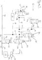
- the braking system adopts the configuration shown in Figure 4 .
- the release of pressure from the supply line 12 and the park line 18 causes the emergency apply valve 20 to move under the action of the biasing means to its second position in which the output is exhausted to atmosphere and the input 20a is closed. Fluid pressure is therefore released from the spring brake chamber 23a of the brake actuator 23 and vented to atmosphere at the emergency apply valve 20, and the actuator 23 moves in response to the spring force to apply the brake.
- the system can be operated to prevent this, specifically by the supply of electrical power to the solenoid 36d of the emergency braking override valve 36.
- This causes the emergency braking override valve 36 to move to its second position wherein the control input 20c of the emergency apply valve 20 is connected to the portion of the emergency apply line 16 between the two one-way check valves 24a, 24b, rather than to the portion of the supply line 16 upstream of the two one-way check valves 24a, 24b.
- Pressurised fluid thus flows from the reservoir 28 to the control input 20c of the emergency apply valve 20, maintained it in or returning it to its first position. Pressurised fluid can then also flow from the reservoir 28 to the spring brake chamber 23a via the emergency apply valve 20, to release the spring brake. This is illustrated in Figure 5 .
- Emergency braking can then, if desired, be effected using the service brake by the supply of electrical power to the solenoid 32d of the brake apply valve 32. Just as described above in relation to Figure 2 , this causes the brake apply valve 32 to move to its second position in which the first input 32a is closed and the second input 32c is connected to the output 32b. In this case however, pressurised fluid passes from the reservoir 28 to the EBS control valve assembly 25 via the brake apply valve 32 and the service brake line 27 to effect service braking.
- the EBS valve assembly can use conventional ABS control algorithms to modify the emergency braking in accordance with standard anti-lock control procedures if wheel slip is detected.
- the braking system 10 may include a pressure sensor 38 in the emergency apply line 16 between the first one way valve 24a and the connection to the park line 18. If this pressure sensor 38 is connected to an electronic control unit (ECU not shown) which controls operation of the electrically operated valves in the braking system (including the brake apply valve 32 and the electrically operated valves in the EBS control valve assembly 25), the ECU can be programmed always to energise the emergency override valve 36 to override the emergency application of the spring brake whenever a sudden drop in the pressure in the emergency apply line 16 is detected, or whenever the pressure in the emergency apply line 16 falls below a predetermined level.
- ECU electronice control unit
- the ECU may alternatively be programmed to energise the emergency braking override valve 36 to override the emergency application of the spring brake when a sudden drop in the pressure in the emergency apply line 16 is detected, or when the pressure in the emergency apply line 16 falls below a predetermined level, but only if certain other predetermined criteria are met - if the vehicle speed exceeds a predetermined level, or if the fluid pressure in the trailer reservoir 28 exceeds a predetermined level, for example.
- the ECU may also be programmed always to activate the brake apply valve 32 when the emergency braking override valve 36 is activated (i.e. to effect emergency service braking when the emergency application of the spring brake is prevented) this need not be the case.
- the ECU may be programmed to activate a signal warning a driver of the vehicle that the supply of pressurised fluid to the supply line 12 has been broken via a CAN bus connection to the driver's cab.
- the signal may be visual - a warning light or the like, or audible - a buzzer, bell or the like, or preferably both.
- the driver may then make a decision to activate the brakes himself, in which case, an electrical braking demand signal is transmitted directly to the brake valve assembly 25 via a CAN bus to effect service braking.
- the ECU may further be programmed such that, once the vehicle has come to a halt, it operates the EBS control valve assembly 25 to hold the pressure in the service brake chamber 23b of the brake actuator 23, whilst the emergency braking override valve 36 is deenergised. This causes the control input 20c of the emergency apply valve 20 to be vented to atmosphere, allowing the emergency apply valve 20 to move to its second position, and venting the spring brake line 21 and spring brake chamber 23a. Once the pressure in the spring brake chamber 23a is exhausted, the spring brake is applied, and the EBS control valve assembly 25 may be operated to exhaust the service brake chamber 23b.
- a further pressure sensor 40 may be provided in the park line 18 between the control input 20c of the emergency apply valve 20 and the output 22b of the park valve 22.
- the further pressure sensor 40 may also be connected to the braking ECU which may be programmed to respond to a sudden reduction in pressure signal from the further pressure sensor 40 in the same way as described above in relation to the first pressure sensor 38.
- the further pressure transducer 40 can be provided instead of the first pressure transducer 38, as the further pressure transducer 40 also detects the loss of pressure in the supply line 16.
- the provision of both pressure transducers 38, 40 allows the system to discriminate between loss of pressure to the control input 20c of the emergency apply valve 20 as a result of loss of supply pressure from the loss of pressure caused by operation of the park valve 22.
- the shunt valve 14 may be operated to release the parking brake without the need for electrical power, for example if the trailer is disconnected from a tractor but needs to be moved around a depot or the like. This can be done by moving the park valve 22 to its first position, and moving the shunt valve 14 to its second position.
- Pressurised fluid flows from the trailer reservoir 28 to the control input 20c of the emergency apply valve 20 via the park line 18 and the park valve 22.
- the pressure at the control input 20c moves the emergency apply valve 20 to its first position and the trailer reservoir 28 is thus connected to the spring brake chamber 23a via the emergency apply line 16, the emergency apply valve 20 and the spring brake line 21.
- the resulting flow of pressurised fluid to the spring brake chamber 23a results in the release of the spring brake.
- the spring brake can be reapplied by returning the shunt valve 14 to its first position.
- the EBS control valve assembly 25 may also include a further double check valve in a line connecting the second portion 21b of the spring brake line 21 to the delivery port of the modulator or one of the modulators in the EBS control valve assembly 25.
- This double check valve is configured such that no flow of fluid along this line is permitted unless, when the spring brake chamber 23a is exhausted (and so the spring brake applied), there is demand for service braking. Then, there is flow of pressurised fluid to the spring brake chamber 23a (to release the spring brake) in addition to flow to the service braking chamber 23b.
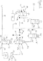
- FIG. 6 A second embodiment of the invention is illustrated in Figure 6 . This is very similar to the embodiment of the invention discussed above and illustrated in Figures 1 to 5 , and differs only in the elements described below. Specifically, the difference resides in the configuration of the emergency braking override valve 36' which, in the second embodiment of the invention has only a first port 36a', which is connected to the output port 22b of the park valve 22, and a second port 36b' which is connected to the control input 20c of the emergency apply valve 20.
- the emergency braking override valve 36' is movable between a first position (illustrated in Figure 6 ) in which its first port 36a' is connected to its second port 36b', and a second position in (illustrated in Figure 7 ) in which flow of fluid between its second port 36b' and its first port 36a' is substantially prevented. Again, the passage of fluid from the supply line 16 to the control input 20c of the emergency apply valve 20 via the park valve 22 is therefore not affected by the emergency braking override valve 36' when the emergency braking override valve 36' is in its first position.
- This embodiment of emergency braking override valve 36' is also electrically operable, in this example, by means of a solenoid 36d', and mechanical biasing means (in this example a spring) is provided to urge the emergency braking override valve 36' into its first position. Movement of the emergency braking override valve 36' from the first position to the second position is achieved by the supply of an electrical current to the solenoid 36d.
- the braking system according to the second embodiment of the invention operates in exactly the same way as the first embodiment of braking system described above in all respects other than when suppression of the emergency application of the spring brake due to loss of pressure in the supply line 12 is required as described below.
- the second embodiment of braking system is shown in normal service braking mode in Figure 6 .
- the system 10 can be operated to prevent this by the supply of electrical power to the solenoid 36d' of the emergency braking override valve 36'. This causes the emergency braking override valve 36' to move to its second position wherein the control input 20c of the emergency apply valve 20 is isolated from the remainder of the system, as illustrated in Figure 7 .
- emergency braking can then, if desired, be effected using the service brake by the supply of electrical power to the solenoid 32d of the brake apply valve 32. Just as described above in relation to Figure 2 , this causes the brake apply valve 32 to move to its second position in which the first input 32a is closed and the second input 32c is connected to the output 32b.
- pressurised fluid passes from the reservoir 28 to the EBS control valve assembly 25 via the brake apply valve 32 and the service brake line 27 to effect service braking.
- the EBS valve assembly can use conventional ABS control algorithms to modify the emergency braking in accordance with standard anti-lock control procedures if wheel slip is detected.
- the ECU is preferably programmed to activate the emergency braking override valve 36' to override the emergency application of the spring brake whenever a sudden drop in the pressure is detected by pressure sensor 40 at the output port 22b of the park valve 22, or when the pressure detected by this pressure sensor 40 falls below a predetermined level.
- the ECU may, however, be programmed to energise the emergency braking override valve 36' to override the emergency application of the spring brake when a sudden drop in the pressure at sensor 40 is detected, or when this pressure falls below a predetermined level, but only if certain other predetermined criteria are met - if the vehicle speed exceeds a predetermined level, or if the fluid pressure in the trailer reservoir 28 exceeds a predetermined level, for example.
- the pressurised fluid used in the invention is preferably compressed air, but any other fluid may be used instead, and the invention could equally be employed in a hydraulic braking system.
- the term "line” covers any type of conduit for pressurised fluid including a passage or bore through a housing, a hose, pipe or tube. It should also be appreciated that, whilst in this example, only one brake actuator 23 is shown, the spring brake line 21 and the EBS valve assembly 25 may be connected to more than one brake actuator.
- the system 10 may also be provided with more than one EBS valve assembly 25.
- one EBS valve assembly 25 may be connected to one or more actuators on one side of the trailer, which a second EBS valve assembly is connected to one or more actuators on the other side of the trailer, with both EBS valve assemblies being connected to the service brake line 27.
Landscapes
- Engineering & Computer Science (AREA)
- Transportation (AREA)
- Mechanical Engineering (AREA)
- Regulating Braking Force (AREA)
- Braking Systems And Boosters (AREA)
Claims (15)
- Fahrzeugbremssystem (10), umfassend einen Bremsaktor (23), der betätigbar ist, um eine Bremsbetätigungsposition, in der der Bremsaktor (23) eine Bremskraft auf ein Fahrzeugrad ausüben kann, und eine Bremsfreigabeposition, in der der Bremsaktor (23) jegliche auf ein Fahrzeugrad ausgeübte Bremskraft freigeben kann, einzunehmen, wobei der Bremsaktor (23) eine Federspeicherbremskammer (23a) und eine Feder aufweist und konfiguriert ist, so dass die Druckfluidversorgung der Federspeicherbremskammer (23a) bewirkt, dass sich der Bremsaktor (23) gegen die Vorspannkraft der Feder in die Bremsfreigabeposition bewegt, und Freigabe von Druckfluid aus der Federspeicherbremskammer (23a) bewirkt, dass sich der Bremsaktor (23) unter der Einwirkung der Feder in die Bremsbetätigungsposition bewegt, wobei das System ferner eine Versorgungsleitung (12), wodurch die Federspeicherbremskammer (23a), im Einsatz, mit einer Druckfluidversorgung verbunden ist, und ein Notbremsbetätigungsventil (20), das eine Steueröffnung (20c) aufweist, die mit der Versorgungsleitung (12) verbunden ist, wobei das Notbremsbetätigungsventil (20) dafür konfiguriert ist, die Federspeicherbremskammer (23a) automatisch mit einem Niederdruckbereich zu verbinden, wenn der Druck an der Steueröffnung (20c) unter ein vorbestimmtes Niveau fällt, beinhaltet, dadurch gekennzeichnet, dass das System ferner ein elektrisch betätigbares Notbremsübersteuerungsventil (36, 36') beinhaltet, das eine erste Öffnung (36a, 36a'), die mit der Versorgungsleitung (12) verbunden ist, und eine zweite Öffnung (36b, 36b'), die mit der Steueröffnung (20c) des Notbremsbetätigungsventils (20) verbunden ist, aufweist und das, bei Versorgung mit genügend elektrischem Strom, wirkt, um Fluiddruckverlust an der Steueröffnung (20c) des Notbremsbetätigungsventils (20) zu verhindern.
- Fahrzeugbremssystem (10) nach Anspruch 1, worin das Notbremsbetätigungsventil (20) eine Eingangsöffnung (20a), die mit der Versorgungsleitung (12) verbunden ist, und eine Ausgangsöffnung (20b), die mit der Federspeicherbremskammer (23a) verbunden ist, aufweist und zwischen einer ersten Position, in der die Eingangsöffnung (20a) mit der Ausgangsöffnung (20b) verbunden ist, und einer zweiten Position, in der die Eingangsöffnung (20a) geschlossen ist und die Ausgangsöffnung (20b) in einen Niederdruckbereich abführt, bewegbar ist.
- Fahrzeugbremssystem (10) nach Anspruch 2, worin ein mechanisches Vorspannmittel vorgesehen ist, um das Notbremsbetätigungsventil (20) in die zweite Position zu drücken, und Bewegung des Notbremsbetätigungsventils von der zweiten Position in die erste Position durch die Zufuhr von Druckfluid zum Steuereingang (20c) mit genügend Druck zum Überwinden der Kraft des Vorspannmittels erreicht wird.
- Fahrzeugbremssystem (10) nach einem vorhergehenden Anspruch, worin der Bremsaktor (23) ferner eine Betriebsbremskammer (23b), worin Zufuhr von Druckfluid zur Betriebsbremskammer (23b) bewirkt, dass sich der Bremsaktor (23) in die Bremsbetätigungsposition bewegt, und eine Steuerleitung (30), die im Einsatz eine Quelle eines Fluiddruck-Bremsanforderungssignals mit der Betriebsbremskammer (23b) über eine Bremsregelventilanordnung (25, 32) verbindet, beinhaltet.
- Fahrzeugbremssystem nach Anspruch 4, worin die Bremsventilanordnung (25, 32) mindestens einen Modulator (25) umfasst, der eine Steueröffnung, die mit der Steuerleitung (30) für den Empfang eines Fluiddruck-Bremsanforderungssignals verbunden ist, eine Versorgungsöffnung, die mit einer Druckfluidquelle verbunden ist, eine Abgabeöffnung, die mit der Betriebsbremskammer verbunden ist, und eine Austrittsöffnung, die in einen Niederdruckbereich abführt, aufweist, wobei der Modulator (25) betätigbar ist, um sich zwischen einer Baukonfiguration, in der die Versorgungsöffnung mit der Abgabeöffnung verbunden ist, während die Austrittsöffnung geschlossen ist, einer Haltekonfiguration, in der die Austrittsöffnung und die Versorgungsöffnungen geschlossen sind, und einer Austrittskonfiguration, in der die Abgabeöffnung mit der Austrittsöffnung verbunden ist, während die Versorgungsöffnung geschlossen ist, zu bewegen.
- Fahrzeugbremssystem (10) nach Anspruch 4 oder 5, worin das Fahrzeugbremssystem (10) ferner einen Druckfluidbehälter (28) umfasst, der mit der Steuerleitung (30) über ein Bremsbetätigungsventil (32) verbunden ist.
- Fahrzeugbremssystem (10) nach Anspruch 6, worin das Bremsbetätigungsventil (32) zwischen einer ersten Konfiguration, in der das Bremsbetätigungsventil (32) einen Fluidfluss vom Druckfluidbehälter (28) zur Steuerleitung (30) im Wesentlichen verhindert, und einer zweiten, in der das Bremsbetätigungsventil (32) einen Fluidfluss vom Druckfluidbehälter (28) zur Steuerleitung (30) gestattet, bewegbar ist.
- Fahrzeugbremssystem (10) nach Anspruch 4, worin ein Rückschlagventil (24a) in der Versorgungsleitung vor der Eingangsöffnung (20a) des Notbremsbetätigungsventils (20) vorgesehen ist, wobei das Rückschlagventil (24a) einen Fluidfluss entlang der Versorgungsleitung (12) zum Notbremsbetätigungsventil (20) gestattet, während ein Fluidfluss in der Gegenrichtung im Wesentlichen verhindert wird.
- Fahrzeugbremssystem (10) nach Anspruch 6 und 8, worin der Druckfluidbehälter (28) mit der Versorgungsleitung (12) nach dem Rückschlagventil (24a) verbunden ist.
- Fahrzeugbremssystem (10) nach Anspruch 8 und 9, worin ein zweites Rückschlagventil (24b) in der Versorgungsleitung (12) vor der Eingangsöffnung (20a) des Notbremsbetätigungsventils (20) vorgesehen ist, wobei das zweite Rückschlagventil (24b) ebenfalls einen Fluidfluss entlang der Versorgungsleitung (12) zum Notbremsbetätigungsventil (20) gestattet, während ein Fluidfluss in der Gegenrichtung im Wesentlichen verhindert wird, und der Druckfluidbehälter (28) mit der Versorgungsleitung (12) zwischen den beiden Rückschlagventilen (24a, 24b) verbunden ist.
- Fahrzeugbremssystem (10) nach Anspruch 8 und einem der Ansprüche 2 bis 7, 9 und 10, worin das Notbremsübersteuerungsventil (36) eine dritte Öffnung (36c) aufweist, die mit der Versorgungsleitung (12) zwischen der ersten Öffnung (20a) des Notbremsbetätigungsventils (20) und dem Anschluss an die Steueröffnung (20c) des Notbremsbetätigungsventils (20) verbunden ist, und die dritte Öffnung (36c) mit der Versorgungsleitung nach dem Rückschlagventil (24a) verbunden ist.
- Fahrzeugbremssystem (10) nach Anspruch 10 und 11, worin die dritte Öffnung (36c) mit der Versorgungsleitung (12) zwischen den beiden Rückschlagventilen (24a, 24b) verbunden ist.
- Fahrzeugbremssystem (10) nach Anspruch 11 oder 12, worin das Notbremsübersteuerungsventil (36) zwischen einer ersten Position, in der seine erste Öffnung (36a) mit seiner zweiten Öffnung (36b) verbunden ist, während seine dritte Öffnung (36c) geschlossen ist, und einer zweiten Position, in der seine dritte Öffnung (36c) mit seiner zweiten Öffnung (36b) verbunden ist, während seine erste Öffnung (36a) geschlossen ist, bewegbar ist.
- Fahrzeugbremssystem (10) nach Anspruch 13, worin das Notbremsübersteuerungsventil (36) mit einem mechanischem Vorspannmittel versehen ist, um das Notbremsübersteuerungsventil (36) in die erste Position zu drücken, wobei Bewegung des Notbremsübersteuerungsventils von der ersten Position in die zweite Position durch Versorgung des Notbremsübersteuerungsventils (36) mit elektrischem Strom erreicht wird.
- Fahrzeugbremssystem (10) nach einem der Ansprüche 1 bis 10, worin das Notbremsübersteuerungsventil (36') zwischen einer ersten Position, in der seine erste Öffnung (36a) mit seiner zweiten Öffnung (36b) verbunden ist, und einer zweiten Position, in der ein Fluidfluss zwischen seiner zweiten Öffnung (36b) und seiner ersten Öffnung (36a) im Wesentlichen verhindert wird, bewegbar ist, und mit einem mechanischen Vorspannmittel versehen ist, um das Notbremsübersteuerungsventil (36) in seine erste Position zu drücken, wobei Bewegung des Notbremsübersteuerungsventils (36) von der ersten Position in die zweite Position durch Versorgung des Notbremsübersteuerungsventils (36) mit elektrischem Strom erreicht wird.
Applications Claiming Priority (2)
| Application Number | Priority Date | Filing Date | Title |
|---|---|---|---|
| GB1110568.1A GB2492124B (en) | 2011-06-22 | 2011-06-22 | Vehicle braking system |
| PCT/GB2012/050659 WO2012175927A1 (en) | 2011-06-22 | 2012-03-26 | Vehicle braking system |
Publications (2)
| Publication Number | Publication Date |
|---|---|
| EP2750949A1 EP2750949A1 (de) | 2014-07-09 |
| EP2750949B1 true EP2750949B1 (de) | 2019-09-11 |
Family
ID=44454469
Family Applications (1)
| Application Number | Title | Priority Date | Filing Date |
|---|---|---|---|
| EP12712350.3A Active EP2750949B1 (de) | 2011-06-22 | 2012-03-26 | Fahrzeugbremssystem |
Country Status (4)
| Country | Link |
|---|---|
| EP (1) | EP2750949B1 (de) |
| GB (1) | GB2492124B (de) |
| HU (1) | HUE047596T2 (de) |
| WO (1) | WO2012175927A1 (de) |
Cited By (1)
| Publication number | Priority date | Publication date | Assignee | Title |
|---|---|---|---|---|
| EP3954589A1 (de) * | 2020-08-14 | 2022-02-16 | Haldex Brake Products AB | Fahrzeugbremssystem |
Families Citing this family (19)
| Publication number | Priority date | Publication date | Assignee | Title |
|---|---|---|---|---|
| DE102013100538B4 (de) * | 2013-01-18 | 2016-06-02 | Haldex Brake Products Gmbh | Druckluftanlage eines Anhängers eines Nutzfahrzeugs |
| DE102015007384A1 (de) * | 2015-06-10 | 2016-12-15 | Wabco Gmbh | Verfahren zum Regeln von Bremsen in einem Anhängefahrzeug |
| GB201517354D0 (en) * | 2015-10-01 | 2015-11-18 | Haldex Brake Products Ltd | Vehicle braking system |
| ITUB20155308A1 (it) * | 2015-10-30 | 2017-04-30 | Studio Tecnico 6M Srl | Dispositivo di frenatura per rimorchi di macchine agricole |
| GB201611713D0 (en) | 2016-07-05 | 2016-08-17 | Haldex Brake Prod Ab | Vehicle braking system |
| US10166956B2 (en) * | 2016-07-28 | 2019-01-01 | Deere & Company | Dual line hydraulic trailer brake control circuit and method of control thereof |
| DE102016011779A1 (de) * | 2016-09-30 | 2018-04-05 | Hydac Accessories Gmbh | Bremsvorrichtung |
| US10093296B2 (en) * | 2017-01-25 | 2018-10-09 | Goodrich Corporation | Electrically activated park and emergency valve with on-valve manual actuation feature |
| DE102017118529B4 (de) | 2017-08-14 | 2019-05-29 | Haldex Brake Products Aktiebolag | Elektronisch gesteuerte Anhänger-Bremssteuereinheit und Anhänger-Bremsanlage |
| DE102018108005A1 (de) | 2018-04-05 | 2019-10-10 | Knorr-Bremse Systeme für Nutzfahrzeuge GmbH | Steuereinrichtung für eine Parkbremseinrichtung eines Fahrzeugs |
| US11186262B2 (en) | 2018-10-11 | 2021-11-30 | Bendix Commercial Vehicle Systems Llc | System and method for controlling compounding in a brake actuator |
| IT201900005228A1 (it) * | 2019-04-05 | 2020-10-05 | Cnh Ind Italia Spa | Valvola di sicurezza migliorata per circuito di frenata idraulico |
| GB2583723B (en) * | 2019-05-03 | 2023-07-05 | Knorr Bremse Systeme Fuer Nutzfahrzeuge Gmbh | Trailer braking system |
| TWI735339B (zh) * | 2020-09-18 | 2021-08-01 | 彥豪金屬工業股份有限公司 | 流體壓力感測裝置及防鎖死煞車組件 |
| EP4043302A1 (de) * | 2021-02-16 | 2022-08-17 | MoRailSo AG | Druckluftbetätigtes bremssystem für einen fahrzeug-anhänger |
| DE102022204480A1 (de) | 2022-05-06 | 2023-11-09 | Zf Friedrichshafen Ag | Betätigungssystem für eine Fahrzeugbremse |
| GB2619076A (en) * | 2022-05-27 | 2023-11-29 | Haldex Brake Prod Ab | A trailer braking system |
| GB2619078A (en) * | 2022-05-27 | 2023-11-29 | Haldex Brake Prod Ab | A trailer braking system |
| GB2621120A (en) * | 2022-07-29 | 2024-02-07 | Haldex Brake Prod Ab | A trailer braking system |
Family Cites Families (7)
| Publication number | Priority date | Publication date | Assignee | Title |
|---|---|---|---|---|
| US4307916A (en) * | 1979-12-20 | 1981-12-29 | Tec Tran Corp. | Hydraulic braking system |
| DE3522183C1 (en) | 1985-06-21 | 1989-08-31 | Graubremse Gmbh | Brake system for vehicles with spring loaded brake cylinders |
| DE20122779U1 (de) * | 2000-09-14 | 2007-08-30 | Wabco Gmbh | Anhängerbremsventil für Anhängefahrzeuge mit elektronischer Bremsregelung und erweiterter Sicherheit des geparkten Anhängers |
| DE10356672B4 (de) | 2003-12-04 | 2006-10-19 | Knorr-Bremse Systeme für Nutzfahrzeuge GmbH | Bremsanlage in einem Fahrzeug |
| DE502004004528D1 (de) * | 2004-12-23 | 2007-09-13 | Db Regio Ag | Notbremsüberbrückung |
| DE102007053765B4 (de) * | 2007-11-12 | 2013-03-21 | Haldex Brake Products Gmbh | Manuell betätigbares Ventil für eine Bremsanlage eines Anhängers |
| DE102009031785A1 (de) | 2009-07-06 | 2011-01-13 | Wabco Gmbh | Pneumatische Bremsanlage für ein Anhängefahrzeug und Bremssteuermodulator |
-
2011
- 2011-06-22 GB GB1110568.1A patent/GB2492124B/en not_active Withdrawn - After Issue
-
2012
- 2012-03-26 HU HUE12712350A patent/HUE047596T2/hu unknown
- 2012-03-26 WO PCT/GB2012/050659 patent/WO2012175927A1/en unknown
- 2012-03-26 EP EP12712350.3A patent/EP2750949B1/de active Active
Non-Patent Citations (1)
| Title |
|---|
| None * |
Cited By (1)
| Publication number | Priority date | Publication date | Assignee | Title |
|---|---|---|---|---|
| EP3954589A1 (de) * | 2020-08-14 | 2022-02-16 | Haldex Brake Products AB | Fahrzeugbremssystem |
Also Published As
| Publication number | Publication date |
|---|---|
| WO2012175927A1 (en) | 2012-12-27 |
| HUE047596T2 (hu) | 2020-04-28 |
| GB201110568D0 (en) | 2011-08-03 |
| GB2492124A (en) | 2012-12-26 |
| GB2492124B (en) | 2017-08-09 |
| EP2750949A1 (de) | 2014-07-09 |
Similar Documents
| Publication | Publication Date | Title |
|---|---|---|
| EP2750949B1 (de) | Fahrzeugbremssystem | |
| EP3150450B1 (de) | Bremssystem für ein fahrzeug | |
| US9809206B2 (en) | Method for braking a traction vehicle-trailer combination with reduced trailer braking force as a function of the response of the ABS of the traction vehicle | |
| US11052892B2 (en) | Electronically controllable pneumatic brake system in a utility vehicle and method for electronically controlling a pneumatic brake system | |
| US9290166B2 (en) | Vehicle braking system | |
| US10953859B2 (en) | Pneumatic braking device for a utility vehicle | |
| US8651588B2 (en) | Electro-pneumatic brake control device | |
| US10654458B2 (en) | Electronic brake system for a compressed air braking system of a utility vehicle | |
| US20050029859A1 (en) | Fluid-pressure brake system for a vehicle | |
| GB2540346A (en) | Vehicle braking system | |
| US10124777B2 (en) | Multiple-stage collision avoidance braking system and method | |
| GB2543037A (en) | Vehicle braking system and valve assembly for controlling a vehicle braking system | |
| GB2490925A (en) | Vehicle braking system | |
| CN111954614A (zh) | 机动车辆液压制动系统及其操作方法 | |
| US20120217794A1 (en) | Traction-slip controlled brake system of a motor vehicle approaching stops | |
| US20180251111A1 (en) | Pneumatic Braking Device | |
| EP1789296B1 (de) | Anhängerbremssystem | |
| US10717423B2 (en) | Method for controlling brakes in a trailer vehicle | |
| GB2509806B (en) | Electrohydraulic antilock brake system with isolation valve | |
| EP3954589B1 (de) | Fahrzeugbremssystem | |
| CN112088115B (zh) | 用于制动系统的冗余制动单元和使用该冗余制动单元的系统 | |
| US20240001900A1 (en) | Trailer Brake Control System | |
| US20240092329A1 (en) | Trailer Brake Control System |
Legal Events
| Date | Code | Title | Description |
|---|---|---|---|
| PUAI | Public reference made under article 153(3) epc to a published international application that has entered the european phase |
Free format text: ORIGINAL CODE: 0009012 |
|
| 17P | Request for examination filed |
Effective date: 20131113 |
|
| AK | Designated contracting states |
Kind code of ref document: A1 Designated state(s): AL AT BE BG CH CY CZ DE DK EE ES FI FR GB GR HR HU IE IS IT LI LT LU LV MC MK MT NL NO PL PT RO RS SE SI SK SM TR |
|
| DAX | Request for extension of the european patent (deleted) | ||
| RAP1 | Party data changed (applicant data changed or rights of an application transferred) |
Owner name: HALDEX BRAKE PRODUCTS AB |
|
| GRAP | Despatch of communication of intention to grant a patent |
Free format text: ORIGINAL CODE: EPIDOSNIGR1 |
|
| STAA | Information on the status of an ep patent application or granted ep patent |
Free format text: STATUS: GRANT OF PATENT IS INTENDED |
|
| INTG | Intention to grant announced |
Effective date: 20190403 |
|
| GRAS | Grant fee paid |
Free format text: ORIGINAL CODE: EPIDOSNIGR3 |
|
| GRAA | (expected) grant |
Free format text: ORIGINAL CODE: 0009210 |
|
| STAA | Information on the status of an ep patent application or granted ep patent |
Free format text: STATUS: THE PATENT HAS BEEN GRANTED |
|
| AK | Designated contracting states |
Kind code of ref document: B1 Designated state(s): AL AT BE BG CH CY CZ DE DK EE ES FI FR GB GR HR HU IE IS IT LI LT LU LV MC MK MT NL NO PL PT RO RS SE SI SK SM TR |
|
| REG | Reference to a national code |
Ref country code: GB Ref legal event code: FG4D |
|
| REG | Reference to a national code |
Ref country code: CH Ref legal event code: EP |
|
| REG | Reference to a national code |
Ref country code: AT Ref legal event code: REF Ref document number: 1178042 Country of ref document: AT Kind code of ref document: T Effective date: 20190915 |
|
| REG | Reference to a national code |
Ref country code: DE Ref legal event code: R096 Ref document number: 602012063850 Country of ref document: DE Ref country code: IE Ref legal event code: FG4D |
|
| REG | Reference to a national code |
Ref country code: NL Ref legal event code: MP Effective date: 20190911 |
|
| REG | Reference to a national code |
Ref country code: LT Ref legal event code: MG4D |
|
| PG25 | Lapsed in a contracting state [announced via postgrant information from national office to epo] |
Ref country code: SE Free format text: LAPSE BECAUSE OF FAILURE TO SUBMIT A TRANSLATION OF THE DESCRIPTION OR TO PAY THE FEE WITHIN THE PRESCRIBED TIME-LIMIT Effective date: 20190911 Ref country code: BG Free format text: LAPSE BECAUSE OF FAILURE TO SUBMIT A TRANSLATION OF THE DESCRIPTION OR TO PAY THE FEE WITHIN THE PRESCRIBED TIME-LIMIT Effective date: 20191211 Ref country code: NO Free format text: LAPSE BECAUSE OF FAILURE TO SUBMIT A TRANSLATION OF THE DESCRIPTION OR TO PAY THE FEE WITHIN THE PRESCRIBED TIME-LIMIT Effective date: 20191211 Ref country code: HR Free format text: LAPSE BECAUSE OF FAILURE TO SUBMIT A TRANSLATION OF THE DESCRIPTION OR TO PAY THE FEE WITHIN THE PRESCRIBED TIME-LIMIT Effective date: 20190911 Ref country code: LT Free format text: LAPSE BECAUSE OF FAILURE TO SUBMIT A TRANSLATION OF THE DESCRIPTION OR TO PAY THE FEE WITHIN THE PRESCRIBED TIME-LIMIT Effective date: 20190911 Ref country code: FI Free format text: LAPSE BECAUSE OF FAILURE TO SUBMIT A TRANSLATION OF THE DESCRIPTION OR TO PAY THE FEE WITHIN THE PRESCRIBED TIME-LIMIT Effective date: 20190911 |
|
| PG25 | Lapsed in a contracting state [announced via postgrant information from national office to epo] |
Ref country code: LV Free format text: LAPSE BECAUSE OF FAILURE TO SUBMIT A TRANSLATION OF THE DESCRIPTION OR TO PAY THE FEE WITHIN THE PRESCRIBED TIME-LIMIT Effective date: 20190911 Ref country code: RS Free format text: LAPSE BECAUSE OF FAILURE TO SUBMIT A TRANSLATION OF THE DESCRIPTION OR TO PAY THE FEE WITHIN THE PRESCRIBED TIME-LIMIT Effective date: 20190911 Ref country code: GR Free format text: LAPSE BECAUSE OF FAILURE TO SUBMIT A TRANSLATION OF THE DESCRIPTION OR TO PAY THE FEE WITHIN THE PRESCRIBED TIME-LIMIT Effective date: 20191212 Ref country code: ES Free format text: LAPSE BECAUSE OF FAILURE TO SUBMIT A TRANSLATION OF THE DESCRIPTION OR TO PAY THE FEE WITHIN THE PRESCRIBED TIME-LIMIT Effective date: 20190911 Ref country code: AL Free format text: LAPSE BECAUSE OF FAILURE TO SUBMIT A TRANSLATION OF THE DESCRIPTION OR TO PAY THE FEE WITHIN THE PRESCRIBED TIME-LIMIT Effective date: 20190911 |
|
| REG | Reference to a national code |
Ref country code: AT Ref legal event code: MK05 Ref document number: 1178042 Country of ref document: AT Kind code of ref document: T Effective date: 20190911 |
|
| REG | Reference to a national code |
Ref country code: HU Ref legal event code: AG4A Ref document number: E047596 Country of ref document: HU |
|
| PG25 | Lapsed in a contracting state [announced via postgrant information from national office to epo] |
Ref country code: NL Free format text: LAPSE BECAUSE OF FAILURE TO SUBMIT A TRANSLATION OF THE DESCRIPTION OR TO PAY THE FEE WITHIN THE PRESCRIBED TIME-LIMIT Effective date: 20190911 Ref country code: EE Free format text: LAPSE BECAUSE OF FAILURE TO SUBMIT A TRANSLATION OF THE DESCRIPTION OR TO PAY THE FEE WITHIN THE PRESCRIBED TIME-LIMIT Effective date: 20190911 Ref country code: IT Free format text: LAPSE BECAUSE OF FAILURE TO SUBMIT A TRANSLATION OF THE DESCRIPTION OR TO PAY THE FEE WITHIN THE PRESCRIBED TIME-LIMIT Effective date: 20190911 Ref country code: AT Free format text: LAPSE BECAUSE OF FAILURE TO SUBMIT A TRANSLATION OF THE DESCRIPTION OR TO PAY THE FEE WITHIN THE PRESCRIBED TIME-LIMIT Effective date: 20190911 Ref country code: RO Free format text: LAPSE BECAUSE OF FAILURE TO SUBMIT A TRANSLATION OF THE DESCRIPTION OR TO PAY THE FEE WITHIN THE PRESCRIBED TIME-LIMIT Effective date: 20190911 Ref country code: PT Free format text: LAPSE BECAUSE OF FAILURE TO SUBMIT A TRANSLATION OF THE DESCRIPTION OR TO PAY THE FEE WITHIN THE PRESCRIBED TIME-LIMIT Effective date: 20200113 Ref country code: PL Free format text: LAPSE BECAUSE OF FAILURE TO SUBMIT A TRANSLATION OF THE DESCRIPTION OR TO PAY THE FEE WITHIN THE PRESCRIBED TIME-LIMIT Effective date: 20190911 |
|
| PG25 | Lapsed in a contracting state [announced via postgrant information from national office to epo] |
Ref country code: IS Free format text: LAPSE BECAUSE OF FAILURE TO SUBMIT A TRANSLATION OF THE DESCRIPTION OR TO PAY THE FEE WITHIN THE PRESCRIBED TIME-LIMIT Effective date: 20200224 Ref country code: SK Free format text: LAPSE BECAUSE OF FAILURE TO SUBMIT A TRANSLATION OF THE DESCRIPTION OR TO PAY THE FEE WITHIN THE PRESCRIBED TIME-LIMIT Effective date: 20190911 Ref country code: CZ Free format text: LAPSE BECAUSE OF FAILURE TO SUBMIT A TRANSLATION OF THE DESCRIPTION OR TO PAY THE FEE WITHIN THE PRESCRIBED TIME-LIMIT Effective date: 20190911 Ref country code: SM Free format text: LAPSE BECAUSE OF FAILURE TO SUBMIT A TRANSLATION OF THE DESCRIPTION OR TO PAY THE FEE WITHIN THE PRESCRIBED TIME-LIMIT Effective date: 20190911 |
|
| REG | Reference to a national code |
Ref country code: DE Ref legal event code: R097 Ref document number: 602012063850 Country of ref document: DE |
|
| PLBE | No opposition filed within time limit |
Free format text: ORIGINAL CODE: 0009261 |
|
| STAA | Information on the status of an ep patent application or granted ep patent |
Free format text: STATUS: NO OPPOSITION FILED WITHIN TIME LIMIT |
|
| PG2D | Information on lapse in contracting state deleted |
Ref country code: IS |
|
| PG25 | Lapsed in a contracting state [announced via postgrant information from national office to epo] |
Ref country code: DK Free format text: LAPSE BECAUSE OF FAILURE TO SUBMIT A TRANSLATION OF THE DESCRIPTION OR TO PAY THE FEE WITHIN THE PRESCRIBED TIME-LIMIT Effective date: 20190911 Ref country code: IS Free format text: LAPSE BECAUSE OF FAILURE TO SUBMIT A TRANSLATION OF THE DESCRIPTION OR TO PAY THE FEE WITHIN THE PRESCRIBED TIME-LIMIT Effective date: 20200112 |
|
| 26N | No opposition filed |
Effective date: 20200615 |
|
| PG25 | Lapsed in a contracting state [announced via postgrant information from national office to epo] |
Ref country code: SI Free format text: LAPSE BECAUSE OF FAILURE TO SUBMIT A TRANSLATION OF THE DESCRIPTION OR TO PAY THE FEE WITHIN THE PRESCRIBED TIME-LIMIT Effective date: 20190911 |
|
| PG25 | Lapsed in a contracting state [announced via postgrant information from national office to epo] |
Ref country code: MC Free format text: LAPSE BECAUSE OF FAILURE TO SUBMIT A TRANSLATION OF THE DESCRIPTION OR TO PAY THE FEE WITHIN THE PRESCRIBED TIME-LIMIT Effective date: 20190911 |
|
| REG | Reference to a national code |
Ref country code: CH Ref legal event code: PL |
|
| REG | Reference to a national code |
Ref country code: BE Ref legal event code: MM Effective date: 20200331 |
|
| PG25 | Lapsed in a contracting state [announced via postgrant information from national office to epo] |
Ref country code: LU Free format text: LAPSE BECAUSE OF NON-PAYMENT OF DUE FEES Effective date: 20200326 |
|
| PG25 | Lapsed in a contracting state [announced via postgrant information from national office to epo] |
Ref country code: IE Free format text: LAPSE BECAUSE OF NON-PAYMENT OF DUE FEES Effective date: 20200326 Ref country code: CH Free format text: LAPSE BECAUSE OF NON-PAYMENT OF DUE FEES Effective date: 20200331 Ref country code: LI Free format text: LAPSE BECAUSE OF NON-PAYMENT OF DUE FEES Effective date: 20200331 |
|
| PG25 | Lapsed in a contracting state [announced via postgrant information from national office to epo] |
Ref country code: BE Free format text: LAPSE BECAUSE OF NON-PAYMENT OF DUE FEES Effective date: 20200331 |
|
| PGFP | Annual fee paid to national office [announced via postgrant information from national office to epo] |
Ref country code: HU Payment date: 20210213 Year of fee payment: 10 |
|
| PG25 | Lapsed in a contracting state [announced via postgrant information from national office to epo] |
Ref country code: TR Free format text: LAPSE BECAUSE OF FAILURE TO SUBMIT A TRANSLATION OF THE DESCRIPTION OR TO PAY THE FEE WITHIN THE PRESCRIBED TIME-LIMIT Effective date: 20190911 Ref country code: MT Free format text: LAPSE BECAUSE OF FAILURE TO SUBMIT A TRANSLATION OF THE DESCRIPTION OR TO PAY THE FEE WITHIN THE PRESCRIBED TIME-LIMIT Effective date: 20190911 Ref country code: CY Free format text: LAPSE BECAUSE OF FAILURE TO SUBMIT A TRANSLATION OF THE DESCRIPTION OR TO PAY THE FEE WITHIN THE PRESCRIBED TIME-LIMIT Effective date: 20190911 |
|
| PG25 | Lapsed in a contracting state [announced via postgrant information from national office to epo] |
Ref country code: MK Free format text: LAPSE BECAUSE OF FAILURE TO SUBMIT A TRANSLATION OF THE DESCRIPTION OR TO PAY THE FEE WITHIN THE PRESCRIBED TIME-LIMIT Effective date: 20190911 |
|
| PG25 | Lapsed in a contracting state [announced via postgrant information from national office to epo] |
Ref country code: HU Free format text: LAPSE BECAUSE OF NON-PAYMENT OF DUE FEES Effective date: 20220327 |
|
| PGFP | Annual fee paid to national office [announced via postgrant information from national office to epo] |
Ref country code: FR Payment date: 20230324 Year of fee payment: 12 |
|
| P01 | Opt-out of the competence of the unified patent court (upc) registered |
Effective date: 20230602 |
|
| P02 | Opt-out of the competence of the unified patent court (upc) changed |
Effective date: 20230619 |
|
| REG | Reference to a national code |
Ref country code: DE Ref legal event code: R082 Ref document number: 602012063850 Country of ref document: DE Representative=s name: MUELLER SCHUPFNER & PARTNER PATENT- UND RECHTS, DE |
|
| PGFP | Annual fee paid to national office [announced via postgrant information from national office to epo] |
Ref country code: DE Payment date: 20240320 Year of fee payment: 13 Ref country code: GB Payment date: 20240201 Year of fee payment: 13 |
|
| REG | Reference to a national code |
Ref country code: GB Ref legal event code: 732E Free format text: REGISTERED BETWEEN 20240404 AND 20240410 |