EP4261474A1 - Relay device and air conditioning device - Google Patents
Relay device and air conditioning device Download PDFInfo
- Publication number
- EP4261474A1 EP4261474A1 EP20965072.0A EP20965072A EP4261474A1 EP 4261474 A1 EP4261474 A1 EP 4261474A1 EP 20965072 A EP20965072 A EP 20965072A EP 4261474 A1 EP4261474 A1 EP 4261474A1
- Authority
- EP
- European Patent Office
- Prior art keywords
- pipe
- heat medium
- path side
- heat
- air conditioning
- Prior art date
- Legal status (The legal status is an assumption and is not a legal conclusion. Google has not performed a legal analysis and makes no representation as to the accuracy of the status listed.)
- Withdrawn
Links
Images





Classifications
-
- F—MECHANICAL ENGINEERING; LIGHTING; HEATING; WEAPONS; BLASTING
- F25—REFRIGERATION OR COOLING; COMBINED HEATING AND REFRIGERATION SYSTEMS; HEAT PUMP SYSTEMS; MANUFACTURE OR STORAGE OF ICE; LIQUEFACTION SOLIDIFICATION OF GASES
- F25B—REFRIGERATION MACHINES, PLANTS OR SYSTEMS; COMBINED HEATING AND REFRIGERATION SYSTEMS; HEAT PUMP SYSTEMS
- F25B41/00—Fluid-circulation arrangements
-
- F—MECHANICAL ENGINEERING; LIGHTING; HEATING; WEAPONS; BLASTING
- F24—HEATING; RANGES; VENTILATING
- F24F—AIR-CONDITIONING; AIR-HUMIDIFICATION; VENTILATION; USE OF AIR CURRENTS FOR SCREENING
- F24F1/00—Room units for air-conditioning, e.g. separate or self-contained units or units receiving primary air from a central station
- F24F1/0007—Indoor units, e.g. fan coil units
- F24F1/0059—Indoor units, e.g. fan coil units characterised by heat exchangers
- F24F1/0063—Indoor units, e.g. fan coil units characterised by heat exchangers by the mounting or arrangement of the heat exchangers
-
- F—MECHANICAL ENGINEERING; LIGHTING; HEATING; WEAPONS; BLASTING
- F24—HEATING; RANGES; VENTILATING
- F24F—AIR-CONDITIONING; AIR-HUMIDIFICATION; VENTILATION; USE OF AIR CURRENTS FOR SCREENING
- F24F13/00—Details common to, or for air-conditioning, air-humidification, ventilation or use of air currents for screening
- F24F13/30—Arrangement or mounting of heat-exchangers
-
- F—MECHANICAL ENGINEERING; LIGHTING; HEATING; WEAPONS; BLASTING
- F25—REFRIGERATION OR COOLING; COMBINED HEATING AND REFRIGERATION SYSTEMS; HEAT PUMP SYSTEMS; MANUFACTURE OR STORAGE OF ICE; LIQUEFACTION SOLIDIFICATION OF GASES
- F25B—REFRIGERATION MACHINES, PLANTS OR SYSTEMS; COMBINED HEATING AND REFRIGERATION SYSTEMS; HEAT PUMP SYSTEMS
- F25B41/00—Fluid-circulation arrangements
- F25B41/20—Disposition of valves, e.g. of on-off valves or flow control valves
- F25B41/24—Arrangement of shut-off valves for disconnecting a part of the refrigerant cycle, e.g. an outdoor part
-
- F—MECHANICAL ENGINEERING; LIGHTING; HEATING; WEAPONS; BLASTING
- F25—REFRIGERATION OR COOLING; COMBINED HEATING AND REFRIGERATION SYSTEMS; HEAT PUMP SYSTEMS; MANUFACTURE OR STORAGE OF ICE; LIQUEFACTION SOLIDIFICATION OF GASES
- F25B—REFRIGERATION MACHINES, PLANTS OR SYSTEMS; COMBINED HEATING AND REFRIGERATION SYSTEMS; HEAT PUMP SYSTEMS
- F25B49/00—Arrangement or mounting of control or safety devices
- F25B49/02—Arrangement or mounting of control or safety devices for compression type machines, plants or systems
-
- F—MECHANICAL ENGINEERING; LIGHTING; HEATING; WEAPONS; BLASTING
- F25—REFRIGERATION OR COOLING; COMBINED HEATING AND REFRIGERATION SYSTEMS; HEAT PUMP SYSTEMS; MANUFACTURE OR STORAGE OF ICE; LIQUEFACTION SOLIDIFICATION OF GASES
- F25B—REFRIGERATION MACHINES, PLANTS OR SYSTEMS; COMBINED HEATING AND REFRIGERATION SYSTEMS; HEAT PUMP SYSTEMS
- F25B5/00—Compression machines, plants or systems, with several evaporator circuits, e.g. for varying refrigerating capacity
- F25B5/02—Compression machines, plants or systems, with several evaporator circuits, e.g. for varying refrigerating capacity arranged in parallel
-
- F—MECHANICAL ENGINEERING; LIGHTING; HEATING; WEAPONS; BLASTING
- F24—HEATING; RANGES; VENTILATING
- F24F—AIR-CONDITIONING; AIR-HUMIDIFICATION; VENTILATION; USE OF AIR CURRENTS FOR SCREENING
- F24F2140/00—Control inputs relating to system states
- F24F2140/20—Heat-exchange fluid temperature
-
- F—MECHANICAL ENGINEERING; LIGHTING; HEATING; WEAPONS; BLASTING
- F25—REFRIGERATION OR COOLING; COMBINED HEATING AND REFRIGERATION SYSTEMS; HEAT PUMP SYSTEMS; MANUFACTURE OR STORAGE OF ICE; LIQUEFACTION SOLIDIFICATION OF GASES
- F25B—REFRIGERATION MACHINES, PLANTS OR SYSTEMS; COMBINED HEATING AND REFRIGERATION SYSTEMS; HEAT PUMP SYSTEMS
- F25B2313/00—Compression machines, plants or systems with reversible cycle not otherwise provided for
- F25B2313/023—Compression machines, plants or systems with reversible cycle not otherwise provided for using multiple indoor units
- F25B2313/0233—Compression machines, plants or systems with reversible cycle not otherwise provided for using multiple indoor units in parallel arrangements
-
- F—MECHANICAL ENGINEERING; LIGHTING; HEATING; WEAPONS; BLASTING
- F25—REFRIGERATION OR COOLING; COMBINED HEATING AND REFRIGERATION SYSTEMS; HEAT PUMP SYSTEMS; MANUFACTURE OR STORAGE OF ICE; LIQUEFACTION SOLIDIFICATION OF GASES
- F25B—REFRIGERATION MACHINES, PLANTS OR SYSTEMS; COMBINED HEATING AND REFRIGERATION SYSTEMS; HEAT PUMP SYSTEMS
- F25B2339/00—Details of evaporators; Details of condensers
- F25B2339/04—Details of condensers
- F25B2339/047—Water-cooled condensers
-
- F—MECHANICAL ENGINEERING; LIGHTING; HEATING; WEAPONS; BLASTING
- F25—REFRIGERATION OR COOLING; COMBINED HEATING AND REFRIGERATION SYSTEMS; HEAT PUMP SYSTEMS; MANUFACTURE OR STORAGE OF ICE; LIQUEFACTION SOLIDIFICATION OF GASES
- F25B—REFRIGERATION MACHINES, PLANTS OR SYSTEMS; COMBINED HEATING AND REFRIGERATION SYSTEMS; HEAT PUMP SYSTEMS
- F25B2400/00—Component parts or details not otherwise provided for in this subclass
- F25B2400/01—Heaters
-
- F—MECHANICAL ENGINEERING; LIGHTING; HEATING; WEAPONS; BLASTING
- F25—REFRIGERATION OR COOLING; COMBINED HEATING AND REFRIGERATION SYSTEMS; HEAT PUMP SYSTEMS; MANUFACTURE OR STORAGE OF ICE; LIQUEFACTION SOLIDIFICATION OF GASES
- F25B—REFRIGERATION MACHINES, PLANTS OR SYSTEMS; COMBINED HEATING AND REFRIGERATION SYSTEMS; HEAT PUMP SYSTEMS
- F25B2400/00—Component parts or details not otherwise provided for in this subclass
- F25B2400/06—Several compression cycles arranged in parallel
-
- F—MECHANICAL ENGINEERING; LIGHTING; HEATING; WEAPONS; BLASTING
- F25—REFRIGERATION OR COOLING; COMBINED HEATING AND REFRIGERATION SYSTEMS; HEAT PUMP SYSTEMS; MANUFACTURE OR STORAGE OF ICE; LIQUEFACTION SOLIDIFICATION OF GASES
- F25B—REFRIGERATION MACHINES, PLANTS OR SYSTEMS; COMBINED HEATING AND REFRIGERATION SYSTEMS; HEAT PUMP SYSTEMS
- F25B2600/00—Control issues
- F25B2600/25—Control of valves
- F25B2600/2519—On-off valves
-
- F—MECHANICAL ENGINEERING; LIGHTING; HEATING; WEAPONS; BLASTING
- F25—REFRIGERATION OR COOLING; COMBINED HEATING AND REFRIGERATION SYSTEMS; HEAT PUMP SYSTEMS; MANUFACTURE OR STORAGE OF ICE; LIQUEFACTION SOLIDIFICATION OF GASES
- F25B—REFRIGERATION MACHINES, PLANTS OR SYSTEMS; COMBINED HEATING AND REFRIGERATION SYSTEMS; HEAT PUMP SYSTEMS
- F25B2700/00—Sensing or detecting of parameters; Sensors therefor
- F25B2700/21—Temperatures
-
- F—MECHANICAL ENGINEERING; LIGHTING; HEATING; WEAPONS; BLASTING
- F25—REFRIGERATION OR COOLING; COMBINED HEATING AND REFRIGERATION SYSTEMS; HEAT PUMP SYSTEMS; MANUFACTURE OR STORAGE OF ICE; LIQUEFACTION SOLIDIFICATION OF GASES
- F25B—REFRIGERATION MACHINES, PLANTS OR SYSTEMS; COMBINED HEATING AND REFRIGERATION SYSTEMS; HEAT PUMP SYSTEMS
- F25B2700/00—Sensing or detecting of parameters; Sensors therefor
- F25B2700/21—Temperatures
- F25B2700/2115—Temperatures of a compressor or the drive means therefor
- F25B2700/21151—Temperatures of a compressor or the drive means therefor at the suction side of the compressor
-
- F—MECHANICAL ENGINEERING; LIGHTING; HEATING; WEAPONS; BLASTING
- F25—REFRIGERATION OR COOLING; COMBINED HEATING AND REFRIGERATION SYSTEMS; HEAT PUMP SYSTEMS; MANUFACTURE OR STORAGE OF ICE; LIQUEFACTION SOLIDIFICATION OF GASES
- F25B—REFRIGERATION MACHINES, PLANTS OR SYSTEMS; COMBINED HEATING AND REFRIGERATION SYSTEMS; HEAT PUMP SYSTEMS
- F25B2700/00—Sensing or detecting of parameters; Sensors therefor
- F25B2700/21—Temperatures
- F25B2700/2115—Temperatures of a compressor or the drive means therefor
- F25B2700/21152—Temperatures of a compressor or the drive means therefor at the discharge side of the compressor
Definitions
- the present disclosure relates to a branch unit and an air conditioning apparatus.
- Refrigerant leakage may occur when air conditioning equipment has a failure or is discarded.
- it is required to reduce the amount of refrigerant to be charged into the air conditioning equipment.
- an air conditioning apparatus that uses a chlorofluorocarbon-based refrigerant for heat transfer between an outdoor unit and a branch unit, and uses water or an anti-freezing solution (a brine) for heat transfer between the branch unit and an indoor unit, in order to reduce the amount of refrigerant to be charged.
- the method for this air conditioning apparatus is called an indirect air conditioning method.
- the present disclosure relates to a branch unit and an air conditioning apparatus that calculate flow rates using electric heaters and temperature sensors, which are generally less expensive than pressure sensors, in order to solve the aforementioned problem.
- the present disclosure relates to a branch unit arranged between a heat source unit using a first heat medium and a plurality of indoor units using a second heat medium.
- the branch unit includes a first heat exchanger and a second heat exchanger, a first pump, a second pump, a plurality of first ports, a plurality of second ports, a flow path switching unit, a plurality of forward path side heaters, and a plurality of first temperature sensors.
- the first heat exchanger and the second heat exchanger are each configured to exchange heat between the first heat medium and the second heat medium.
- the first pump is configured to send the second heat medium so as to circulate the second heat medium through the first heat exchanger.
- the second pump is configured to send the second heat medium so as to circulate the second heat medium through the second heat exchanger.
- the second heat medium is sent to one corresponding indoor unit of the plurality of indoor units.
- the second heat medium returning from one corresponding indoor unit of the plurality of indoor units is received.
- the flow path switching unit is configured to connect each of the plurality of first ports and the plurality of second ports to one of the first heat exchanger and the second heat exchanger.
- the plurality of forward path side heaters are respectively provided for a plurality of forward path side pipes through which the second heat medium is sent to the plurality of first ports.
- the plurality of first temperature sensors are respectively arranged, at the plurality of forward path side pipes, downstream of the plurality of forward path side heaters.
- the branch unit and the air conditioning apparatus of the present disclosure it is possible to implement an air conditioning apparatus that can calculate flow rates of a heat medium using electric heaters and temperature sensors which are generally less expensive, and that achieves cost reduction.
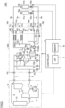
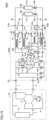
- Fig. 1 is a view showing a configuration of an air conditioning apparatus 100 in a first embodiment.
- Air conditioning apparatus 100 has a heat source unit 10, a branch unit 30, and a plurality of indoor units 50a and 50b.
- Heat source unit 10 is usually an outdoor unit arranged outside, and operates as a heat source or a cold source.
- the present embodiment describes an air conditioning apparatus having two indoor units, three or more indoor units may be connected to the heat source unit via the branch unit.
- Heat source unit 10 is connected with branch unit 30 by a first pipe 1 and a second pipe 2.
- Indoor unit 50a is connected with branch unit 30 by a third pipe 3a and a fourth pipe 4a.
- Indoor unit 50b is connected with branch unit 30 by a third pipe 3b and a fourth pipe 4b.
- Heat source unit 10 includes a compressor 11, a six-way valve 12, and an outdoor heat exchanger 13.
- Six-way valve 12 is configured such that three flow paths are formed therein.
- Six ports of six-way valve 12 are connected to a pipe 5 on a discharge side of compressor 11, a pipe 6 on a suction side of compressor 11, first pipe 1, second pipe 2, and pipes 7 and 8 at inlet and outlet portions of outdoor heat exchanger 13, respectively.
- Indoor unit 50a includes an indoor heat exchanger 51a and a flow control valve 52a.
- Third pipe 3a, indoor heat exchanger 51a, flow control valve 52a, and fourth pipe 4a are connected in order between a port P1A and a port P2A of branch unit 30.
- Indoor unit 50b includes an indoor heat exchanger 51b and a flow control valve 52b.
- Third pipe 3b, indoor heat exchanger 51b, flow control valve 52b, and fourth pipe 4b are connected in order between a port P1B and a port P2B of branch unit 30.
- Branch unit 30 includes heat exchangers 61a and 61b, as shown in Fig. 1 .
- Each of heat exchangers 61a and 61b performs heat exchange between two fluids. Flow paths through which the two fluids flow within each heat exchanger will be referred to as a primary side flow path and a secondary side flow path, respectively.
- a chlorofluorocarbon-based refrigerant As a heat medium flowing through the primary side flow path on a heat source side (hereinafter referred to as a first heat medium), a chlorofluorocarbon-based refrigerant is used. The chlorofluorocarbon-based refrigerant circulates through first pipe 1 and second pipe 2. As a heat medium flowing through the secondary side flow path on a load side (hereinafter referred to as a second heat medium), water or an anti-freezing solution (a brine) is used. The water or the anti-freezing solution circulates through third pipe 3a, fourth pipe 4a, third pipe 3b, and fourth pipe 4b.
- One end of the primary side flow path of heat exchanger 61a is connected to pipe 1 via an on-off valve 71a and a port P3, and is connected to pipe 2 via an on-off valve 72a and a port P4.
- One end of the primary side flow path of heat exchanger 61b is connected to pipe 1 via an on-off valve 71b and port P3, and is connected to pipe 2 via an on-off valve 72b and port P4.
- the other end of the primary side flow path of heat exchanger 61a and the other end of the primary side flow path of heat exchanger 61b are connected and joined via flow control valves 62a and 62b, respectively, and a junction point thereof is connected to pipe 1 via a first flow control valve 81 and port P3, and to pipe 2 via a second flow control valve 82 and port P4.
- Branch unit 30 includes pumps 60a and 60b, as shown in Fig. 1 .
- a discharge port of pump 60a is connected to one end of the secondary side flow path of heat exchanger 61a.
- the other end of the secondary side flow path of heat exchanger 61a is connected to pipe 3a via an on-off valve 91, and is connected to pipe 3b via an on-off valve 93.
- a discharge port of pump 60a is connected to pipe 4a via an on-off valve 95, and is connected to pipe 4b via an on-off valve 97.
- An outflow side of pump 60b goes through a secondary side of heat exchanger 61b, and thereafter is connected to pipe 3a via an on-off valve 92, and is connected to pipe 3b via an on-off valve 94. Further, an inflow side of pump 60b is connected to pipe 4a via an on-off valve 96, and is connected to pipe 4b via an on-off valve 98.
- flow control valves 52a and 52b may be respectively arranged on pipes 32a and 32b within the branch unit, to which pipes 4a and 4b are connected. Further, flow control valves 52a and 52b may be respectively arranged on pipes 31a and 31b within the branch unit, to which pipes 3a and 3b are connected. It should be noted that, if on-off valves 91 to 98 can each adjust an opening area thereof, it is also possible to reduce the number of components as well as cost by causing on-off valves 91 to 98 to provide a flow control function without providing flow control valves 52a and 52b.
- a primary side as a heat source unit 10 side, and the secondary side as an indoor unit 50 side as well as the load side, are independently provided as separate circuits.
- the first heat medium and the second heat medium which are separate fluids, can be used as the heat medium on the primary side and the heat medium on the secondary side.
- a chlorofluorocarbon-based refrigerant suitable for a vapor compression refrigeration cycle is used as the first heat medium on the heat source side.
- the chlorofluorocarbon-based refrigerant is considered problematic in terms of contribution to global warming and flammability, and it is required to reduce the amount of refrigerant to be used and reduce the risk of leakage to a closed space.
- Air conditioning apparatus 100 adopts such a simultaneous cooling and heating-type air conditioning method.
- Air conditioning apparatus 100 has four operation modes, that is, a "full-cooling mode”, a “full-heating mode”, "a first simultaneous cooling and heating operation mode”, and "a second simultaneous cooling and heating operation mode”.
- the full-cooling mode is a mode in which both indoor units 50a and 50b perform cooling operation.
- the full-heating mode is a mode in which both indoor units 50a and 50b perform heating operation.
- the first simultaneous cooling and heating operation mode is a mode in which indoor unit 50a performs cooling operation and indoor unit 50b performs heating operation.
- the second simultaneous cooling and heating operation mode is a mode in which indoor unit 50a performs heating operation and indoor unit 50b performs cooling operation.
- the first simultaneous cooling and heating operation mode may be an operation mode in which cooling is dominant, such as a case where the number of units for cooling operation is more than the number of units for heating operation.
- the second simultaneous cooling and heating operation mode may be an operation mode in which heating is dominant, such as a case where the number of units for cooling operation is less than the number of units for heating operation.
- Fig. 1 In the full-cooling mode, three flow paths indicated by solid lines in Fig. 1 are formed within six-way valve 12.
- branch unit 30 on-off valves 71a and 71b are opened, and on-off valves 72a and 72b are closed. Further, flow control valve 81 is closed, and flow control valve 82 is opened.
- the degree of opening of each of flow control valves 62a and 62b is controlled by a controller 70 to correspond to a flow rate of the first heat medium required.
- Both heat exchangers 61a and 61b serve as evaporators, and cool the second heat medium.
- the cooled second heat medium is distributed to indoor heat exchangers 51a and 51b by on-off valves 91 to 98, and cool indoor air.
- Fig. 1 In the full-heating mode, three flow paths indicated by broken lines in Fig. 1 are formed within six-way valve 12.
- branch unit 30 on-off valves 71a and 71b are closed, and on-off valves 72a and 72b are opened. Further, flow control valve 82 is closed, and flow control valve 81 is opened.
- the degree of opening of each of flow control valves 62a and 62b is controlled by controller 70 to correspond to a flow rate of the first heat medium required.
- Both heat exchangers 61a and 61b serve as condensers, and heat the second heat medium.
- the heated second heat medium is distributed to indoor heat exchangers 51a and 51b by on-off valves 91 to 98, and heat the indoor air.
- on-off valves 71b and 72a and flow control valves 81 and 82 are closed, and the three flow paths indicated by the solid lines in Fig. 1 are formed within six-way valve 12.
- the first heat medium flows from compressor 11, via pipe 7, outdoor heat exchanger 13, pipe 2, and on-off valve 72b, to reach heat exchanger 61b serving as a condenser, and expands at flow control valve 62b and is changed to have a low temperature and a low pressure.
- the first heat medium passes through flow control valve 62a and heat exchanger 61a serving as an evaporator, flows via on-off valve 71a, pipe 1, six-way valve 12, and pipe 6, and returns to compressor 11.
- heat exchanger 61b serves as a heat source for heating
- heat exchanger 61a serves as a cold source for cooling
- on-off valves 91 to 98 switch whether to connect flow paths corresponding to indoor units 50a and 50b to the heat source or to the cold source.
- on-off valves 91 to 98 are controlled such that indoor unit 50a performs cooling operation and indoor unit 50b performs heating operation
- on-off valves 91 to 98 are controlled such that indoor unit 50a performs heating operation and indoor unit 50b performs cooling operation.
- the flow paths indicated by the broken lines may be formed within six-way valve 12, flow control valves 81 and 82 and on-off valves 71a and 72b may be closed, and the first heat medium may flow in order of on-off valve 72a, heat exchanger 61a, flow control valves 62a and 62b, heat exchanger 61b, and on-off valve 71b.
- heat exchanger 61a serves as a heat source for heating
- heat exchanger 61b serves as a cold source for cooling.
- Air conditioning apparatus 100 further includes controller 70.
- Controller 70 includes a CPU (Central Processing Unit) 71, a memory 72 (a ROM (Read Only Memory) and a RAM (Random Access Memory)), input/output buffers (not shown) for inputting/outputting various signals, and the like.
- CPU 71 expands programs stored in the ROM onto the RAM or the like and executes the programs.
- the programs stored in the ROM are programs describing processing procedures of controller 70. According to these programs, controller 70 performs control of devices in air conditioning apparatus 100. This control can be processed not only by software but also by dedicated hardware (electronic circuitry).
- Controller 70 may be arranged within a case of one of heat source unit 10, branch unit 30, and indoor units 50a and 50b, or may be arranged on a control panel or the like different therefrom.
- controller 70 receives measurement values of temperature sensors T1, T3, T11, T12, Tai, Tao, Tbi, and Tbo, to perform calculation of a flow rate G of the second heat medium and calculation of an air conditioning capability Q in each of indoor units 50a and 50b. Accordingly, controller 70 is desirably arranged within the case of branch unit 30 or on the control panel or the like arranged in the vicinity of branch unit 30.
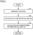
- Fig. 2 is a flowchart for illustrating calculation of flow rates and air conditioning capabilities in the first embodiment.
- Controller 70 energizes heaters in step S1, calculates flow rates Ga and Gb of the second heat medium flowing through indoor units 50a and 50b in step S2, and calculates air conditioning capabilities Qa and Qb of indoor units 50a and 50b in step S3.
- a method for calculating flow rates Ga and Gb of the second heat medium flowing through indoor units 50a and 50b and calculating air conditioning capabilities Qa and Qb of indoor units 50a and 50b in the first embodiment will be described below.
- Flow rates Ga and Gb will be collectively represented as flow rate G
- air conditioning capabilities Qa and Qb will be collectively represented as air conditioning capability Q.
- indoor unit 50a starts cooling operation
- heat exchanger 61a has a low temperature by the action of operation of heat source unit 10
- corresponding pump 60a is driven
- on-off valves 91 and 95 are opened
- on-off valves 92 and 96 are closed.
- Temperature sensor Tai measures a temperature of the second heat medium that flows out of pump 60a.
- Temperature sensor Tao measures a temperature of the second heat medium that flows into a secondary side of heat exchanger 61a, is cooled, and flows out of heat exchanger 61a. Thereafter, the second heat medium flows through a forward path side thermal bonding portion within pipe 31a that connects between port P1A and on-off valve 91 for selecting a secondary side outlet of heat exchanger 61a. On that occasion, the second heat medium is heated by a heater 201 attached to the forward path side thermal bonding portion. Temperature sensor T1 measures a temperature of the heated second heat medium. The second heat medium thereafter flows through third pipe 3a and reaches indoor unit 50a.
- the temperature of the second heat medium is increased by cooling the indoor air in indoor unit 50a. Then, the second heat medium flows through fourth pipe 4a, on-off valve 95, and a return path side intra-unit pipe, and reaches pump 60a. Temperature sensor T11 measures a temperature of the second heat medium that flows out of indoor unit 50a.
- a heating amount H (kW) of the second heat medium is determined from power consumption of heater 201.
- a temperature variation range ⁇ T (°C) of the second heat medium is determined from a difference between detection values T1 and Tao of temperature sensor T1 and temperature sensor Tao.
- a temperature difference ⁇ (°C) at an inlet and an outlet of indoor unit 50a is determined from a difference between detection values T1 and T11 of temperature sensor T1 and temperature sensor T11.
- flow rate G kg/sec
- temperature difference ⁇ T1-T1 1
- air conditioning capability Q kW
- air conditioning capability Q of each indoor unit can be calculated by the same computing equation.
- a method for calculating the flow rate of the heat medium using pressure sensors will be considered.
- the pressure sensors it is necessary to arrange the pressure sensors before and after a flow control valve to measure a differential pressure before and after the flow control valve.
- a flow control valve is attached within an indoor unit
- a flow control valve is attached within a branch unit.
- the pressure of the second heat medium decreases gradually as it moves in a flow direction within a pipe, due to pressure loss caused by friction against a wall surface within the pipe. Accordingly, in order to calculate the flow rate of the second heat medium with high accuracy, it is more desirable to attach the pressure sensors immediately before and immediately after the flow control valve.
- the pressure sensors are also attached within the same indoor unit, and when a flow control valve is attached within a branch unit, the pressure sensors are also attached within the same branch unit.
- pressure sensors are not used to calculate the flow rate. Accordingly, the method for calculating the flow rate of the heat medium disclosed in the first embodiment is independent of the positions of the flow control valves. In the first embodiment, information required to compute the air conditioning capabilities of the respective indoor units is completed within branch unit 30. Thus, collective management for computation at high frequency in controller 70 provided within branch unit 30 or in the vicinity of branch unit 30 can be implemented, and an air conditioning apparatus system independent of the presence or absence of flow control valves 52a and 52b of indoor units 50a and 50b can be configured.
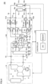
- Fig. 3 is a view showing a configuration of an air conditioning apparatus 100A in a variation of the first embodiment.
- Air conditioning apparatus 100A includes a branch unit 30A instead of branch unit 30 in the configuration of air conditioning apparatus 100 in Fig. 1 .
- Branch unit 30A includes heaters 201A and 202A instead of heaters 201 and 202 in the configuration of branch unit 30 shown in Fig. 1 .
- heaters 201 and 202 are arranged on a side close to ports P1A and P1B with respect to a flow path switching unit 90.
- heaters 201A and 202A are arranged on a side close to first heat exchanger 61a and second heat exchanger 61b with respect to flow path switching unit 90, and are each configured to heat both of two branched pipes.
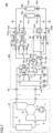
- Fig. 4 is a view showing a configuration of an air conditioning apparatus 200 in a second embodiment.
- Air conditioning apparatus 200 includes a branch unit 230 instead of branch unit 30, and includes a controller 270 instead of controller 70, in the configuration of air conditioning apparatus 100 in Fig. 1 .
- Branch unit 230 further includes heaters 203 and 204 and temperature sensors T56 and T78 in the configuration of branch unit 30 shown in Fig. 1 .
- branch unit 230 includes heater 203 configured to heat the second heat medium within pipe 32a connected to fourth pipe 4a, and heater 204 configured to heat the second heat medium within pipe 32b connected to fourth pipe 4b.
- Temperature sensors T56 and T78 are arranged downstream of heaters 203 and 204, respectively.
- the second heat medium at a low temperature before reaching indoor unit 50a or 50b is heated for the purpose of calculating the flow rate, and thereby cooling capability is reduced.
- the second heat medium returning from the indoor unit is heated by a heater attached downstream of the indoor unit, and thereby influence on indoor cooling capability can be eliminated.
- Fig. 5 is a flowchart for illustrating calculation of flow rates and air conditioning capabilities in the second embodiment.
- Controller 270 determines, in step S11, whether or not indoor unit 50a performs heating operation. When indoor unit 50a performs heating operation (YES in S11), controller 270 energizes heater 201 in step S12. When indoor unit 50a performs cooling operation (NO in S11), controller 270 energizes heater 203 in step S13.
- controller 270 determines, in step S14, whether or not indoor unit 50b performs heating operation. When indoor unit 50b performs heating operation (YES in S14), controller 270 energizes heater 202 in step S15. When indoor unit 50b performs cooling operation (NO in S14), controller 270 energizes heater 204 in step S16.
- controller 270 calculates flow rates Ga and Gb of the second heat medium flowing through indoor units 50a and 50b, respectively, in step S17, and calculates air conditioning capabilities Qa and Qb of indoor units 50a and 50b, respectively, in step S18. Since the methods for calculating flow rate G and air conditioning capability Q are the same as those in the first embodiment, the descriptions thereof will not be repeated here.
- Fig. 6 is a view showing a configuration of an air conditioning apparatus 200A in a variation of the second embodiment.
- Air conditioning apparatus 200A includes a branch unit 230A instead of branch unit 230 in the configuration of air conditioning apparatus 200 in Fig. 4 .
- heaters 201 and 202 are respectively arranged on the side close to ports P1A and P1B with respect to flow path switching unit 90, and heaters 203 and 204 are respectively arranged on a side close to ports P2A and P2B with respect to flow path switching unit 90.
- heaters 201 and 202 are arranged on the side close to first heat exchanger 61a and second heat exchanger 61b with respect to flow path switching unit 90, and are each configured to heat both of two branched pipes.
- heaters 203 and 204 are arranged on a side close to pumps 60a and 60b with respect to flow path switching unit 90, and are each configured to heat both of two branched pipes. Temperature sensors T5 and T6 are arranged downstream of heater 203, and temperature sensors T7 and T8 are arranged downstream of heater 204.
- Fig. 7 is a view showing a configuration of an air conditioning apparatus 300 in a third embodiment.
- Air conditioning apparatus 300 includes a branch unit 330 instead of branch unit 30 in the configuration of air conditioning apparatus 100 in Fig. 1 . It should be noted that Fig. 7 does not show a controller corresponding to controller 70.
- Branch unit 330 is configured such that forward path side intra-unit pipes 31a and 31b each have a branched portion and a junction portion, and a plurality of flow paths extending in parallel between the branched portion and the junction portion.
- the flow paths extending in parallel have pipe diameters different from each other, and the flow path having a smaller pipe cross sectional area is configured to be heated by a heater.
- pipe 31a has a branched portion and a junction portion, and a first pipe 31a1 and a second pipe 31a2 connected in parallel between the branched portion and the junction portion.
- First pipe 31a1 and second pipe 31a2 have pipe diameters different from each other.
- Second pipe 31a2 has a cross sectional area smaller than that of first pipe 31a1.
- Heater 201 is arranged such that second pipe 31a2 having a smaller cross sectional area is heated by heater 201.
- Temperature sensor T1 is arranged downstream of a portion of second pipe 31a2 heated by heater 201.
- pipe 31b has a branched portion and a junction portion, and a first pipe 31b1 and a second pipe 31b2 connected in parallel between the branched portion and the junction portion.
- First pipe 31b1 and second pipe 31b2 have pipe diameters different from each other.
- Second pipe 31b2 has a cross sectional area smaller than that of first pipe 31b1.
- Heater 202 is arranged such that second pipe 31b2 having a smaller cross sectional area is heated by heater 202.
- Temperature sensor T3 is arranged downstream of a portion of second pipe 31b2 heated by heater 202.
- ratios between intra-pipe cross sectional areas of second pipes 31a2 and 31b2 (bypass flow paths) and intra-pipe cross sectional areas of first pipes 31a1 and 31b1 (main flow paths) are known. Since the ratio between the flow rate of the second heat medium within a bypass flow path and the flow rate thereof within a main flow path is equal to the ratio between the intra-pipe cross sectional areas thereof, the flow rate within the main flow path can be determined from the flow rate within the bypass flow path. Therefore, in the third embodiment, when flow rates and air conditioning capabilities of indoor units are computed, power consumption of the heaters can be reduced, in addition to the effect in the first embodiment.
- Fig. 8 is a view showing a configuration of an air conditioning apparatus 300A in a variation of the third embodiment.
- Air conditioning apparatus 300A includes a branch unit 330A instead of branch unit 330 in the configuration of air conditioning apparatus 300 in Fig. 7 .
- heaters 201 and 202 are respectively arranged on the side close to ports P1A and P1B with respect to flow path switching unit 90.
- heaters 201 and 202 are arranged on the side close to first heat exchanger 61a and second heat exchanger 61b with respect to flow path switching unit 90, and are each configured to heat both bypass flow paths of two branched pipes.
- Fig. 9 is a view showing a configuration of an air conditioning apparatus 400 in a fourth embodiment.
- the fourth embodiment is a combination of the first to third embodiments.
- Air conditioning apparatus 400 includes a branch unit 430 instead of branch unit 330 in the configuration of air conditioning apparatus 300 in Fig. 7 . It should be noted that Fig. 9 does not show a controller.
- branch unit 430 is configured such that return path side intra-unit pipes 32a and 32b each have a branched portion and a junction portion, and a plurality of flow paths extending in parallel between the branched portion and the junction portion.
- the flow paths extending in parallel have pipe diameters different from each other, and the flow path having a smaller pipe cross sectional area is configured to be heated by a heater.
- pipe 32a has a branched portion and a junction portion, and a first pipe 32a1 and a second pipe 32a2 connected in parallel between the branched portion and the junction portion.
- First pipe 32a1 and second pipe 32a2 have pipe diameters different from each other.
- Second pipe 32a2 has a cross sectional area smaller than that of first pipe 32a1.
- Heater 203 is arranged such that second pipe 32a2 having a smaller cross sectional area is heated by heater 203.
- Temperature sensor T56 is arranged downstream of a portion of second pipe 32a2 heated by heater 203.
- pipe 32b has a branched portion and a junction portion, and a first pipe 32b1 and a second pipe 32b2 connected in parallel between the branched portion and the junction portion.
- First pipe 32b1 and second pipe 32b2 have pipe diameters different from each other.
- Second pipe 32b2 has a cross sectional area smaller than that of first pipe 32b1.
- Heater 204 is arranged such that second pipe 32b2 having a smaller cross sectional area is heated by heater 204.
- Temperature sensor T78 is arranged downstream of a portion of second pipe 32b2 heated by heater 204.
- Fig. 10 is a view showing a configuration of an air conditioning apparatus 400A in a variation of the fourth embodiment.
- Air conditioning apparatus 400A includes a branch unit 430A instead of branch unit 430 in the configuration of air conditioning apparatus 400 in Fig. 9 .
- heaters 201 and 202 are respectively arranged on the side close to ports P1A and P1B with respect to flow path switching unit 90, and heaters 203 and 204 are respectively arranged on the side close to ports P2A and P2B with respect to flow path switching unit 90.
- heaters 203 and 204 are respectively arranged on the side close to ports P2A and P2B with respect to flow path switching unit 90.
- heaters 201 and 202 are arranged on the side close to first heat exchanger 61a and second heat exchanger 61b with respect to flow path switching unit 90
- heaters 203 and 204 are arranged on the side close to pumps 60a and 60b with respect to flow path switching unit 90
- each heater is configured to heat both bypass flow paths of two branched pipes
- temperature sensors T5, T6, T7, and T8 are arranged downstream of the heaters for the bypass flow paths.
- the controller controls timing at which power is supplied to the heaters in the configurations of the first to fourth embodiments.
- the pumps in the branch unit are also stopped, and it is not necessary to measure the flow rates by the heaters.
- energization of the heaters is controlled even in such a case to reduce power consumption.
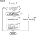
- Fig. 11 is a flowchart for illustrating control of energization of the heaters performed in the fifth embodiment.
- control is applied to the configuration of the first embodiment in Fig. 1 . It should be noted that the same control can also be applied to the other embodiments.
- step S51 controller 70 determines whether or not air conditioning apparatus 100 is in operation. When air conditioning apparatus 100 is not in operation (NO in S51), the processing of this flowchart is exited. When air conditioning apparatus 100 is in operation (YES in S51), the processing proceeds to step S52.
- step S52 controller 70 determines whether a time for measuring flow rates G has come (or whether flow rates G are being measured) or not.
- step S52 the controller energizes heaters 201 and 202 in step S53. Then, in step S53, the controller calculates flow rates G and air conditioning capabilities Q using the equations (1) and (2) in the first embodiment.
- the controller turns off heaters 201 and 202 in step S54.
- the time for measurement in step S52 is a time from a measurement start time to a measurement finish time, and is one minute, for example. Further, measurement is started every 10 minutes, for example, and when the one-minute time for measurement finishes, the heaters are de-energized for the remaining nine minutes. In this case, power consumption of the heaters can be reduced to one tenth even when the indoor units perform operation.
- the configuration in the fifth embodiment has a measurement off mode.
- the measurement off mode power supply to all the forward path side heaters (and all the return path side heaters) is stopped while at least one indoor unit is in operation. Since the air conditioning capabilities of the indoor units rarely change significantly and frequently, it is practically unnecessary to constantly compute the air conditioning capabilities by constantly energizing the heaters.
- the measurement off mode is provided for a constant time at constant intervals, and energy saving can be achieved by reducing power consumption of the heaters.
- Branch unit 30 shown in Fig. 1 includes first heat exchanger 61a and second heat exchanger 61b, first pump 60a, second pump 60b, a plurality of first ports P1A and P1B, a plurality of second ports P2A and P2B, flow path switching unit 90, a plurality of forward path side heaters 201 and 202, and a plurality of first temperature sensors T1 and T3.
- First heat exchanger 61a and second heat exchanger 61b are each configured to exchange heat between the first heat medium and the second heat medium.
- First pump 60a is configured to send the second heat medium so as to circulate the second heat medium through first heat exchanger 61a.
- Second pump 60b is configured to send the second heat medium so as to circulate the second heat medium through second heat exchanger 61b.
- the second heat medium is able to be sent to one corresponding indoor unit of the plurality of indoor units 50a and 50b.
- the second heat medium returning from one corresponding indoor unit of the plurality of indoor units 50a and 50b is able to be received.
- Flow path switching unit 90 is configured to connect each of the plurality of first ports P1A and P1B and the plurality of second ports P2A and P2B to one of first heat exchanger 61a and second heat exchanger 61b.
- the plurality of forward path side heaters 201 and 202 are respectively provided for a plurality of forward path side pipes 31a and 31b through which the second heat medium is able to be sent to the plurality of first ports P1A and P1B.
- the plurality of first temperature sensors T1 and T3 are respectively arranged, at the plurality of forward path side pipes 31a and 31b, downstream of the plurality of forward path side heaters 201 and 202.
- the sensors can be arranged with a higher degree of freedom when compared with a case where pressure sensors are used.
- the temperature sensors are collectively arranged in branch unit 30, load of communication between the indoor units and the branch unit is reduced, which is advantageous in terms of performing fine control.
- each of the plurality of forward path side pipes 31a and 31b includes first pipe 31a1, 31b1 and second pipe 31a2, 31b2.
- Second pipes 31a2 and 31b2 have flow path cross sectional areas smaller than those of first pipes 31a1 and 31b1, respectively, and are configured to be branched from first pipes 31a1 and 31b1, respectively, and thereafter join first pipes 31a1 and 31b1 again, respectively.
- Each of the plurality of first temperature sensors T1 and T3 and each of the plurality of forward path side heaters 201 and 202 are arranged at second pipe 31a2, 31b2 corresponding thereto.
- branch unit 230 further includes a plurality of return path side heaters 203 and 204, and a plurality of second temperature sensors T56 and T78.
- the plurality of return path side heaters 203 and 204 are respectively provided for a plurality of return path side pipes 32a and 32b through which the second heat medium flowing into the plurality of second ports P2A and P2B passes.
- the plurality of second temperature sensors T56 and T78 are respectively arranged, at the plurality of return path side pipes 32a and 32b, downstream of the plurality of return path side heaters 203 and 204.
- the plurality of return path side pipes 32a and 32b include third pipes 32a1 and 32b1 and fourth pipes 32a2 and 32b2, respectively.
- Fourth pipes 32a2 and 32b2 have flow path cross sectional areas smaller than those of third pipes 32a1 and 32b1, respectively, and are configured to be branched from third pipes 32a1 and 32b1, respectively, and thereafter join third pipes 32a1 and 32b1 again, respectively.
- Each of the plurality of second temperature sensors T11 and T12 and each of the plurality of return path side heaters 203 and 204 are arranged at fourth pipe 32a2, 32b2 corresponding thereto.
- Branch unit 30 further includes controller 70 configured to control first pump 60a, second pump 60b, flow path switching unit 90, and the plurality of forward path side heaters 201 and 202.
- controller 70 is configured to repeat a measurement mode and a measurement off mode when at least one of the plurality of indoor units 50a and 50b is in operation, the measurement mode being a mode in which at least one of the plurality of forward path side heaters 201 and 202 is turned on to measure flow rate Ga, Gb, the measurement off mode being a mode in which all of the plurality of forward path side heaters 201 and 202 are turned off.
- the second heat medium is water or an anti-freezing solution.
- the present disclosure relates to an air conditioning apparatus 100, 200, 300, 400 including: any one of branch units 30, 130, 230, 330, and 430; heat source unit 10; and the plurality of indoor units 50a and 50b.
Landscapes
- Engineering & Computer Science (AREA)
- Mechanical Engineering (AREA)
- General Engineering & Computer Science (AREA)
- Physics & Mathematics (AREA)
- Thermal Sciences (AREA)
- Chemical & Material Sciences (AREA)
- Combustion & Propulsion (AREA)
- Air Conditioning Control Device (AREA)
- Other Air-Conditioning Systems (AREA)
Abstract
Description
- The present disclosure relates to a branch unit and an air conditioning apparatus.
- Refrigerant leakage may occur when air conditioning equipment has a failure or is discarded. In order to reduce the influence of refrigerant leakage on global environment, it is required to reduce the amount of refrigerant to be charged into the air conditioning equipment. There is known an air conditioning apparatus that uses a chlorofluorocarbon-based refrigerant for heat transfer between an outdoor unit and a branch unit, and uses water or an anti-freezing solution (a brine) for heat transfer between the branch unit and an indoor unit, in order to reduce the amount of refrigerant to be charged. The method for this air conditioning apparatus is called an indirect air conditioning method.
- In air conditioning of a large-scale building, there may be a case where a plurality of indoor units are connected to a common outdoor unit, and a plurality of rooms where the plurality of indoor units are respectively installed are owned or used by different owners or users. In such a case, there are some market demands to apportion a power consumption charge of the outdoor unit according to air conditioning capabilities exhibited by the respective indoor units installed in the respective rooms or tenants. In particular, in air conditioning equipment that adopts the indirect air conditioning method, it is relatively easy to measure flow rates and temperatures, and thus systems for apportioning and billing power consumption of the air conditioning equipment have already been widespread in the market.
- For example, there is known a method of providing pressure sensors before and after a flow control valve, calculating a flow rate of a heat medium from an opening area of the valve and a differential pressure before and after the valve, and calculating a heat exchange amount (air conditioning capability) using a difference in temperatures of the heat medium at an inlet and an outlet of a heat exchanger (see, for example,
Japanese Patent No. 6678837 - PTL 1:
Japanese Patent No. 6678837 - However, in the air conditioning apparatus and the method for calculating the flow rate of the heat medium disclosed in
Japanese Patent No. 6678837 - The present disclosure relates to a branch unit and an air conditioning apparatus that calculate flow rates using electric heaters and temperature sensors, which are generally less expensive than pressure sensors, in order to solve the aforementioned problem.
- The present disclosure relates to a branch unit arranged between a heat source unit using a first heat medium and a plurality of indoor units using a second heat medium. The branch unit includes a first heat exchanger and a second heat exchanger, a first pump, a second pump, a plurality of first ports, a plurality of second ports, a flow path switching unit, a plurality of forward path side heaters, and a plurality of first temperature sensors.
- The first heat exchanger and the second heat exchanger are each configured to exchange heat between the first heat medium and the second heat medium. The first pump is configured to send the second heat medium so as to circulate the second heat medium through the first heat exchanger. The second pump is configured to send the second heat medium so as to circulate the second heat medium through the second heat exchanger.
- Via each of the plurality of first ports, the second heat medium is sent to one corresponding indoor unit of the plurality of indoor units. Via each of the plurality of second ports, the second heat medium returning from one corresponding indoor unit of the plurality of indoor units is received.
- The flow path switching unit is configured to connect each of the plurality of first ports and the plurality of second ports to one of the first heat exchanger and the second heat exchanger.
- The plurality of forward path side heaters are respectively provided for a plurality of forward path side pipes through which the second heat medium is sent to the plurality of first ports. The plurality of first temperature sensors are respectively arranged, at the plurality of forward path side pipes, downstream of the plurality of forward path side heaters.
- According to the branch unit and the air conditioning apparatus of the present disclosure, it is possible to implement an air conditioning apparatus that can calculate flow rates of a heat medium using electric heaters and temperature sensors which are generally less expensive, and that achieves cost reduction.
-
-
Fig. 1 is a view showing a configuration of anair conditioning apparatus 100 in a first embodiment. -
Fig. 2 is a flowchart for illustrating calculation of flow rates and air conditioning capabilities in the first embodiment. -
Fig. 3 is a view showing a configuration of anair conditioning apparatus 100A in a variation of the first embodiment. -
Fig. 4 is a view showing a configuration of anair conditioning apparatus 200 in a second embodiment. -
Fig. 5 is a flowchart for illustrating calculation of flow rates and air conditioning capabilities in the second embodiment. -
Fig. 6 is a view showing a configuration of anair conditioning apparatus 200A in a variation of the second embodiment. -
Fig. 7 is a view showing a configuration of anair conditioning apparatus 300 in a third embodiment. -
Fig. 8 is a view showing a configuration of anair conditioning apparatus 300A in a variation of the third embodiment. -
Fig. 9 is a view showing a configuration of anair conditioning apparatus 400 in a fourth embodiment. -
Fig. 10 is a view showing a configuration of anair conditioning apparatus 400A in a variation of the fourth embodiment. -
Fig. 11 is a flowchart for illustrating control of energization of heaters performed in a fifth embodiment. - Hereinafter, embodiments of the present disclosure will be described in detail with reference to the drawings. Although a plurality of embodiments will be described below, it is originally intended from the time of filing the present application to combine configurations described in the embodiments as appropriate. It should be noted that identical or corresponding parts in the drawings will be designated by the same reference characters, and the description thereof will not be repeated.
-
Fig. 1 is a view showing a configuration of anair conditioning apparatus 100 in a first embodiment.Air conditioning apparatus 100 has aheat source unit 10, abranch unit 30, and a plurality ofindoor units Heat source unit 10 is usually an outdoor unit arranged outside, and operates as a heat source or a cold source. Although the present embodiment describes an air conditioning apparatus having two indoor units, three or more indoor units may be connected to the heat source unit via the branch unit. -
Heat source unit 10 is connected withbranch unit 30 by afirst pipe 1 and asecond pipe 2.Indoor unit 50a is connected withbranch unit 30 by athird pipe 3a and afourth pipe 4a.Indoor unit 50b is connected withbranch unit 30 by athird pipe 3b and afourth pipe 4b. -
Heat source unit 10 includes acompressor 11, a six-way valve 12, and anoutdoor heat exchanger 13. Six-way valve 12 is configured such that three flow paths are formed therein. Six ports of six-way valve 12 are connected to apipe 5 on a discharge side ofcompressor 11, apipe 6 on a suction side ofcompressor 11,first pipe 1,second pipe 2, andpipes outdoor heat exchanger 13, respectively. -
Indoor unit 50a includes anindoor heat exchanger 51a and aflow control valve 52a.Third pipe 3a,indoor heat exchanger 51a,flow control valve 52a, andfourth pipe 4a are connected in order between a port P1A and a port P2A ofbranch unit 30. -
Indoor unit 50b includes anindoor heat exchanger 51b and aflow control valve 52b.Third pipe 3b,indoor heat exchanger 51b,flow control valve 52b, andfourth pipe 4b are connected in order between a port P1B and a port P2B ofbranch unit 30. -
Branch unit 30 includesheat exchangers Fig. 1 . Each ofheat exchangers - As a heat medium flowing through the primary side flow path on a heat source side (hereinafter referred to as a first heat medium), a chlorofluorocarbon-based refrigerant is used. The chlorofluorocarbon-based refrigerant circulates through
first pipe 1 andsecond pipe 2. As a heat medium flowing through the secondary side flow path on a load side (hereinafter referred to as a second heat medium), water or an anti-freezing solution (a brine) is used. The water or the anti-freezing solution circulates throughthird pipe 3a,fourth pipe 4a,third pipe 3b, andfourth pipe 4b. - One end of the primary side flow path of
heat exchanger 61a is connected topipe 1 via an on-offvalve 71a and a port P3, and is connected topipe 2 via an on-offvalve 72a and a port P4. One end of the primary side flow path ofheat exchanger 61b is connected topipe 1 via an on-offvalve 71b and port P3, and is connected topipe 2 via an on-offvalve 72b and port P4. - The other end of the primary side flow path of
heat exchanger 61a and the other end of the primary side flow path ofheat exchanger 61b are connected and joined viaflow control valves pipe 1 via a firstflow control valve 81 and port P3, and topipe 2 via a secondflow control valve 82 and port P4. -
Branch unit 30 includespumps Fig. 1 . A discharge port ofpump 60a is connected to one end of the secondary side flow path ofheat exchanger 61a. The other end of the secondary side flow path ofheat exchanger 61a is connected topipe 3a via an on-offvalve 91, and is connected topipe 3b via an on-offvalve 93. Further, a discharge port ofpump 60a is connected topipe 4a via an on-offvalve 95, and is connected topipe 4b via an on-offvalve 97. - An outflow side of
pump 60b goes through a secondary side ofheat exchanger 61b, and thereafter is connected topipe 3a via an on-offvalve 92, and is connected topipe 3b via an on-offvalve 94. Further, an inflow side ofpump 60b is connected topipe 4a via an on-offvalve 96, and is connected topipe 4b via an on-offvalve 98. - Meanwhile, flow
control valves pipes pipes flow control valves pipes pipes valves 91 to 98 can each adjust an opening area thereof, it is also possible to reduce the number of components as well as cost by causing on-offvalves 91 to 98 to provide a flow control function without providingflow control valves - In
air conditioning apparatus 100 in the first embodiment, viaheat exchangers branch unit 30, a primary side as aheat source unit 10 side, and the secondary side as an indoor unit 50 side as well as the load side, are independently provided as separate circuits. Thereby, the first heat medium and the second heat medium, which are separate fluids, can be used as the heat medium on the primary side and the heat medium on the secondary side. - Generally, as the first heat medium on the heat source side, a chlorofluorocarbon-based refrigerant suitable for a vapor compression refrigeration cycle is used. However, the chlorofluorocarbon-based refrigerant is considered problematic in terms of contribution to global warming and flammability, and it is required to reduce the amount of refrigerant to be used and reduce the risk of leakage to a closed space.
- Accordingly, by using water or an anti-freezing solution as the second heat medium on the load side, it is possible to reduce the amount of the chlorofluorocarbon-based refrigerant to be used on the primary side, and reduce the risk of refrigerant leakage to an indoor environment which is a closed space.
- Further, in air conditioning of a large-scale building, there may be a case where heating is required in an office room, whereas cooling is required in a room in which heat is generated, such as a computer room, a kitchen, and the like. In such a case, there is known an air conditioning apparatus in which each indoor unit can arbitrarily select cooling or heating regardless of the operation state of cooling or heating of another indoor unit. Such an air conditioning apparatus has a configuration in which a plurality of indoor units are connected to a common outdoor unit via a branch unit. Such an air conditioning method by which one air conditioning apparatus can simultaneously operate air conditioning for cooling and air conditioning for heating is referred to as simultaneous cooling and heating method.
Air conditioning apparatus 100 adopts such a simultaneous cooling and heating-type air conditioning method. -
Air conditioning apparatus 100 has four operation modes, that is, a "full-cooling mode", a "full-heating mode", "a first simultaneous cooling and heating operation mode", and "a second simultaneous cooling and heating operation mode". - The full-cooling mode is a mode in which both
indoor units indoor units indoor unit 50a performs cooling operation andindoor unit 50b performs heating operation. The second simultaneous cooling and heating operation mode is a mode in whichindoor unit 50a performs heating operation andindoor unit 50b performs cooling operation. - It should be noted that, when there are three or more indoor units, the first simultaneous cooling and heating operation mode may be an operation mode in which cooling is dominant, such as a case where the number of units for cooling operation is more than the number of units for heating operation. The second simultaneous cooling and heating operation mode may be an operation mode in which heating is dominant, such as a case where the number of units for cooling operation is less than the number of units for heating operation.
- In the full-cooling mode, three flow paths indicated by solid lines in
Fig. 1 are formed within six-way valve 12. Inbranch unit 30, on-offvalves valves flow control valve 81 is closed, and flowcontrol valve 82 is opened. The degree of opening of each offlow control valves controller 70 to correspond to a flow rate of the first heat medium required. Bothheat exchangers indoor heat exchangers valves 91 to 98, and cool indoor air. - In the full-heating mode, three flow paths indicated by broken lines in
Fig. 1 are formed within six-way valve 12. Inbranch unit 30, on-offvalves valves flow control valve 82 is closed, and flowcontrol valve 81 is opened. The degree of opening of each offlow control valves controller 70 to correspond to a flow rate of the first heat medium required. Bothheat exchangers indoor heat exchangers valves 91 to 98, and heat the indoor air. - In the simultaneous cooling and heating operation modes, on-off
valves control valves Fig. 1 are formed within six-way valve 12. - The first heat medium flows from
compressor 11, viapipe 7,outdoor heat exchanger 13,pipe 2, and on-offvalve 72b, to reachheat exchanger 61b serving as a condenser, and expands atflow control valve 62b and is changed to have a low temperature and a low pressure. - Thereafter, the first heat medium passes through
flow control valve 62a andheat exchanger 61a serving as an evaporator, flows via on-offvalve 71a,pipe 1, six-way valve 12, andpipe 6, and returns tocompressor 11. - In this case,
heat exchanger 61b serves as a heat source for heating, andheat exchanger 61a serves as a cold source for cooling. - According to whether each of
indoor units valves 91 to 98 switch whether to connect flow paths corresponding toindoor units - In the first simultaneous cooling and heating operation mode, on-off
valves 91 to 98 are controlled such thatindoor unit 50a performs cooling operation andindoor unit 50b performs heating operation, and in the second simultaneous cooling and heating operation mode, on-offvalves 91 to 98 are controlled such thatindoor unit 50a performs heating operation andindoor unit 50b performs cooling operation. - It should be noted that, in simultaneous cooling and heating operation, the flow paths indicated by the broken lines may be formed within six-
way valve 12,flow control valves valves valve 72a,heat exchanger 61a,flow control valves heat exchanger 61b, and on-offvalve 71b. In this case,heat exchanger 61a serves as a heat source for heating, andheat exchanger 61b serves as a cold source for cooling. -
Air conditioning apparatus 100 further includescontroller 70.Controller 70 includes a CPU (Central Processing Unit) 71, a memory 72 (a ROM (Read Only Memory) and a RAM (Random Access Memory)), input/output buffers (not shown) for inputting/outputting various signals, and the like.CPU 71 expands programs stored in the ROM onto the RAM or the like and executes the programs. The programs stored in the ROM are programs describing processing procedures ofcontroller 70. According to these programs,controller 70 performs control of devices inair conditioning apparatus 100. This control can be processed not only by software but also by dedicated hardware (electronic circuitry). -
Controller 70 may be arranged within a case of one ofheat source unit 10,branch unit 30, andindoor units - In the present embodiment,
controller 70 receives measurement values of temperature sensors T1, T3, T11, T12, Tai, Tao, Tbi, and Tbo, to perform calculation of a flow rate G of the second heat medium and calculation of an air conditioning capability Q in each ofindoor units controller 70 is desirably arranged within the case ofbranch unit 30 or on the control panel or the like arranged in the vicinity ofbranch unit 30. -
Fig. 2 is a flowchart for illustrating calculation of flow rates and air conditioning capabilities in the first embodiment.Controller 70 energizes heaters in step S1, calculates flow rates Ga and Gb of the second heat medium flowing throughindoor units indoor units - A method for calculating flow rates Ga and Gb of the second heat medium flowing through
indoor units indoor units - For example, it is assumed that
indoor unit 50a starts cooling operation,heat exchanger 61a has a low temperature by the action of operation ofheat source unit 10, correspondingpump 60a is driven, on-offvalves valves - Temperature sensor Tai measures a temperature of the second heat medium that flows out of
pump 60a. Temperature sensor Tao measures a temperature of the second heat medium that flows into a secondary side ofheat exchanger 61a, is cooled, and flows out ofheat exchanger 61a. Thereafter, the second heat medium flows through a forward path side thermal bonding portion withinpipe 31a that connects between port P1A and on-offvalve 91 for selecting a secondary side outlet ofheat exchanger 61a. On that occasion, the second heat medium is heated by aheater 201 attached to the forward path side thermal bonding portion. Temperature sensor T1 measures a temperature of the heated second heat medium. The second heat medium thereafter flows throughthird pipe 3a and reachesindoor unit 50a. The temperature of the second heat medium is increased by cooling the indoor air inindoor unit 50a. Then, the second heat medium flows throughfourth pipe 4a, on-offvalve 95, and a return path side intra-unit pipe, and reachespump 60a. Temperature sensor T11 measures a temperature of the second heat medium that flows out ofindoor unit 50a. - Here, when
heater 201 is an electric heater, a heating amount H (kW) of the second heat medium is determined from power consumption ofheater 201. A temperature variation range ΔT (°C) of the second heat medium is determined from a difference between detection values T1 and Tao of temperature sensor T1 and temperature sensor Tao. Using heating amount H (kW), temperature variation range ΔT = T1-Tao, and a specific heat Cp (kJ/(kg·°C)) of the heat medium, flow rate G (kg/sec) of the heat medium can be calculated by the following equation (1):
- A temperature difference Δθ (°C) at an inlet and an outlet of
indoor unit 50a is determined from a difference between detection values T1 and T11 of temperature sensor T1 and temperature sensor T11. Using flow rate G (kg/sec) of the heat medium flowing throughindoor unit 50a described above, and temperature difference Δθ = T1-T1 1, air conditioning capability Q (kW) ofindoor unit 50a can be calculated by the following equation (2):
- When
indoor unit 50a performs heating operation, even if the heat exchanger having a low temperature changes fromheat exchanger 61a toheat exchanger 61b due to the operation state ofheat source unit 10 and the operation state of anotherindoor unit 50b, air conditioning capability Q of each indoor unit can be calculated by the same computing equation. - Unlike the present embodiment, a method for calculating the flow rate of the heat medium using pressure sensors will be considered. In the method using the pressure sensors, it is necessary to arrange the pressure sensors before and after a flow control valve to measure a differential pressure before and after the flow control valve. Generally, there are a configuration in which a flow control valve is attached within an indoor unit, and a configuration in which a flow control valve is attached within a branch unit. The pressure of the second heat medium decreases gradually as it moves in a flow direction within a pipe, due to pressure loss caused by friction against a wall surface within the pipe. Accordingly, in order to calculate the flow rate of the second heat medium with high accuracy, it is more desirable to attach the pressure sensors immediately before and immediately after the flow control valve.
- That is, when a flow control valve is attached within an indoor unit, the pressure sensors are also attached within the same indoor unit, and when a flow control valve is attached within a branch unit, the pressure sensors are also attached within the same branch unit.
- When a flow control valve is attached within an indoor unit, there is an advantage that fine control of the flow rate of the heat medium according to indoor temperature can be implemented by a microcomputer within the indoor unit. However, it is necessary to transmit information about air conditioning capabilities of respective indoor units for apportioning a power charge to the respective indoor units, to microcomputers of an outdoor unit and a branch unit on each occasion, which may put a pressure on communication capacity.
- On the other hand, when a flow control valve is attached within a branch unit, the amount of communication between the branch unit and an indoor unit about control of the flow control valve is reduced, and information about air conditioning capabilities of respective indoor units can be collectively managed for computation at high frequency in the microcomputer within the branch unit. However, it is impossible to obtain information about the indoor units and the indoor temperatures at high frequency from the microcomputers within the indoor units, because it puts a pressure on communication capacity. Thus, fine control of the flow rate of the heat medium according to indoor temperature cannot be implemented.
- In the first embodiment, pressure sensors are not used to calculate the flow rate. Accordingly, the method for calculating the flow rate of the heat medium disclosed in the first embodiment is independent of the positions of the flow control valves. In the first embodiment, information required to compute the air conditioning capabilities of the respective indoor units is completed within
branch unit 30. Thus, collective management for computation at high frequency incontroller 70 provided withinbranch unit 30 or in the vicinity ofbranch unit 30 can be implemented, and an air conditioning apparatus system independent of the presence or absence offlow control valves indoor units -
Fig. 3 is a view showing a configuration of anair conditioning apparatus 100A in a variation of the first embodiment.Air conditioning apparatus 100A includes abranch unit 30A instead ofbranch unit 30 in the configuration ofair conditioning apparatus 100 inFig. 1 .Branch unit 30A includesheaters heaters branch unit 30 shown inFig. 1 . - In the configuration in
Fig. 1 ,heaters path switching unit 90. In contrast, in the configuration inFig. 3 ,heaters first heat exchanger 61a andsecond heat exchanger 61b with respect to flowpath switching unit 90, and are each configured to heat both of two branched pipes. - By adopting such an arrangement, it may also be possible to arrange the heaters by utilizing vacant spaces within the branch unit.
-
Fig. 4 is a view showing a configuration of anair conditioning apparatus 200 in a second embodiment.Air conditioning apparatus 200 includes abranch unit 230 instead ofbranch unit 30, and includes acontroller 270 instead ofcontroller 70, in the configuration ofair conditioning apparatus 100 inFig. 1 .Branch unit 230 further includesheaters branch unit 30 shown inFig. 1 . - That is,
branch unit 230 includesheater 203 configured to heat the second heat medium withinpipe 32a connected tofourth pipe 4a, andheater 204 configured to heat the second heat medium withinpipe 32b connected tofourth pipe 4b. Temperature sensors T56 and T78 are arranged downstream ofheaters - In the first embodiment, when
indoor unit indoor unit -
Fig. 5 is a flowchart for illustrating calculation of flow rates and air conditioning capabilities in the second embodiment. -
Controller 270 determines, in step S11, whether or notindoor unit 50a performs heating operation. Whenindoor unit 50a performs heating operation (YES in S11),controller 270 energizesheater 201 in step S12. Whenindoor unit 50a performs cooling operation (NO in S11),controller 270 energizesheater 203 in step S13. - Further,
controller 270 determines, in step S14, whether or notindoor unit 50b performs heating operation. Whenindoor unit 50b performs heating operation (YES in S14),controller 270 energizesheater 202 in step S15. Whenindoor unit 50b performs cooling operation (NO in S14),controller 270 energizesheater 204 in step S16. - Thereafter,
controller 270 calculates flow rates Ga and Gb of the second heat medium flowing throughindoor units indoor units -
Fig. 6 is a view showing a configuration of anair conditioning apparatus 200A in a variation of the second embodiment.Air conditioning apparatus 200A includes abranch unit 230A instead ofbranch unit 230 in the configuration ofair conditioning apparatus 200 inFig. 4 . - In the configuration in
Fig. 4 ,heaters path switching unit 90, andheaters path switching unit 90. In contrast, in the configuration inFig. 6 ,heaters first heat exchanger 61a andsecond heat exchanger 61b with respect to flowpath switching unit 90, and are each configured to heat both of two branched pipes. Similarly, in the configuration inFig. 6 ,heaters pumps path switching unit 90, and are each configured to heat both of two branched pipes. Temperature sensors T5 and T6 are arranged downstream ofheater 203, and temperature sensors T7 and T8 are arranged downstream ofheater 204. - By adopting such an arrangement, it may also be possible to arrange the heaters by utilizing vacant spaces within the branch unit.
-
Fig. 7 is a view showing a configuration of anair conditioning apparatus 300 in a third embodiment.Air conditioning apparatus 300 includes abranch unit 330 instead ofbranch unit 30 in the configuration ofair conditioning apparatus 100 inFig. 1 . It should be noted thatFig. 7 does not show a controller corresponding tocontroller 70. -
Branch unit 330 is configured such that forward path sideintra-unit pipes - Specifically,
pipe 31a has a branched portion and a junction portion, and a first pipe 31a1 and a second pipe 31a2 connected in parallel between the branched portion and the junction portion. First pipe 31a1 and second pipe 31a2 have pipe diameters different from each other. Second pipe 31a2 has a cross sectional area smaller than that of first pipe 31a1.Heater 201 is arranged such that second pipe 31a2 having a smaller cross sectional area is heated byheater 201. Temperature sensor T1 is arranged downstream of a portion of second pipe 31a2 heated byheater 201. - Similarly,
pipe 31b has a branched portion and a junction portion, and a first pipe 31b1 and a second pipe 31b2 connected in parallel between the branched portion and the junction portion. First pipe 31b1 and second pipe 31b2 have pipe diameters different from each other. Second pipe 31b2 has a cross sectional area smaller than that of first pipe 31b1.Heater 202 is arranged such that second pipe 31b2 having a smaller cross sectional area is heated byheater 202. Temperature sensor T3 is arranged downstream of a portion of second pipe 31b2 heated byheater 202. - In the first and second embodiments, it is necessary to heat the entire water flow amount flowing through an indoor unit by a heater to increase temperature. In contrast, in the third embodiment, it is only necessary to heat a flow amount of the second heat medium flowing through bypass pipe 31a2 having a smaller cross sectional area by
heater 201 to increase temperature, and it is only necessary to heat a flow amount of the second heat medium flowing through bypass pipe 31b2 byheater 202 to increase temperature. Considering that it is only necessary to heat the second heat medium by the heaters by the same temperature increase range under the condition that the temperature sensors have the same precision and resolution, power consumption of the heaters can be reduced by ratios of bypass flow rates in second pipes 31a2 and 31b2 to flow rates in first pipes 31a1 and 31b1. - It should be noted that ratios between intra-pipe cross sectional areas of second pipes 31a2 and 31b2 (bypass flow paths) and intra-pipe cross sectional areas of first pipes 31a1 and 31b1 (main flow paths) are known. Since the ratio between the flow rate of the second heat medium within a bypass flow path and the flow rate thereof within a main flow path is equal to the ratio between the intra-pipe cross sectional areas thereof, the flow rate within the main flow path can be determined from the flow rate within the bypass flow path. Therefore, in the third embodiment, when flow rates and air conditioning capabilities of indoor units are computed, power consumption of the heaters can be reduced, in addition to the effect in the first embodiment.
-
Fig. 8 is a view showing a configuration of anair conditioning apparatus 300A in a variation of the third embodiment.Air conditioning apparatus 300A includes abranch unit 330A instead ofbranch unit 330 in the configuration ofair conditioning apparatus 300 inFig. 7 . - In the configuration in
Fig. 7 ,heaters path switching unit 90. In contrast, in the configuration inFig. 8 ,heaters first heat exchanger 61a andsecond heat exchanger 61b with respect to flowpath switching unit 90, and are each configured to heat both bypass flow paths of two branched pipes. - By adopting such an arrangement, it may also be possible to arrange the heaters by utilizing vacant spaces within the branch unit.
-
Fig. 9 is a view showing a configuration of anair conditioning apparatus 400 in a fourth embodiment. The fourth embodiment is a combination of the first to third embodiments.Air conditioning apparatus 400 includes abranch unit 430 instead ofbranch unit 330 in the configuration ofair conditioning apparatus 300 inFig. 7 . It should be noted thatFig. 9 does not show a controller. - When compared with the configuration of
branch unit 330,branch unit 430 is configured such that return path sideintra-unit pipes - Specifically,
pipe 32a has a branched portion and a junction portion, and a first pipe 32a1 and a second pipe 32a2 connected in parallel between the branched portion and the junction portion. First pipe 32a1 and second pipe 32a2 have pipe diameters different from each other. Second pipe 32a2 has a cross sectional area smaller than that of first pipe 32a1.Heater 203 is arranged such that second pipe 32a2 having a smaller cross sectional area is heated byheater 203. Temperature sensor T56 is arranged downstream of a portion of second pipe 32a2 heated byheater 203. - Similarly,
pipe 32b has a branched portion and a junction portion, and a first pipe 32b1 and a second pipe 32b2 connected in parallel between the branched portion and the junction portion. First pipe 32b1 and second pipe 32b2 have pipe diameters different from each other. Second pipe 32b2 has a cross sectional area smaller than that of first pipe 32b1.Heater 204 is arranged such that second pipe 32b2 having a smaller cross sectional area is heated byheater 204. Temperature sensor T78 is arranged downstream of a portion of second pipe 32b2 heated byheater 204. - With such a configuration, adverse influence of heating by the heaters on the indoor units during cooling can be reduced, and power consumption of the heaters can be reduced.
-
Fig. 10 is a view showing a configuration of anair conditioning apparatus 400A in a variation of the fourth embodiment.Air conditioning apparatus 400A includes abranch unit 430A instead ofbranch unit 430 in the configuration ofair conditioning apparatus 400 inFig. 9 . - In the configuration in
Fig. 9 ,heaters path switching unit 90, andheaters path switching unit 90. In contrast, in the configuration inFig. 10 ,heaters first heat exchanger 61a andsecond heat exchanger 61b with respect to flowpath switching unit 90,heaters pumps path switching unit 90, each heater is configured to heat both bypass flow paths of two branched pipes, and temperature sensors T5, T6, T7, and T8 are arranged downstream of the heaters for the bypass flow paths. - By adopting such an arrangement, it may also be possible to arrange the heaters by utilizing vacant spaces within the branch unit.
- In a fifth embodiment, the controller controls timing at which power is supplied to the heaters in the configurations of the first to fourth embodiments. When all the indoor units do not perform operation, the pumps in the branch unit are also stopped, and it is not necessary to measure the flow rates by the heaters. However, when at least any one of the indoor units performs operation, it is necessary to calculate air conditioning capability of the indoor unit for billing purposes and the like.
- In the fifth embodiment, energization of the heaters is controlled even in such a case to reduce power consumption.
-
Fig. 11 is a flowchart for illustrating control of energization of the heaters performed in the fifth embodiment. In the following, a description will be given of a case where the control is applied to the configuration of the first embodiment inFig. 1 . It should be noted that the same control can also be applied to the other embodiments. - In step S51,
controller 70 determines whether or notair conditioning apparatus 100 is in operation. Whenair conditioning apparatus 100 is not in operation (NO in S51), the processing of this flowchart is exited. Whenair conditioning apparatus 100 is in operation (YES in S51), the processing proceeds to step S52. - In step S52,
controller 70 determines whether a time for measuring flow rates G has come (or whether flow rates G are being measured) or not. - When the time for measurement has come (YES in S52), the controller energizes
heaters - On the other hand, when the time for measurement has not come (NO in S52), the controller turns off
heaters - The time for measurement in step S52 is a time from a measurement start time to a measurement finish time, and is one minute, for example. Further, measurement is started every 10 minutes, for example, and when the one-minute time for measurement finishes, the heaters are de-energized for the remaining nine minutes. In this case, power consumption of the heaters can be reduced to one tenth even when the indoor units perform operation.
- As has been described above, the configuration in the fifth embodiment has a measurement off mode. In the measurement off mode, power supply to all the forward path side heaters (and all the return path side heaters) is stopped while at least one indoor unit is in operation. Since the air conditioning capabilities of the indoor units rarely change significantly and frequently, it is practically unnecessary to constantly compute the air conditioning capabilities by constantly energizing the heaters. In the fifth embodiment, the measurement off mode is provided for a constant time at constant intervals, and energy saving can be achieved by reducing power consumption of the heaters.
- The embodiments described above will be described again with reference to the drawings.
- The present disclosure relates to branch
unit 30 arranged betweenheat source unit 10 using the first heat medium and the plurality ofindoor units Branch unit 30 shown inFig. 1 includesfirst heat exchanger 61a andsecond heat exchanger 61b,first pump 60a,second pump 60b, a plurality of first ports P1A and P1B, a plurality of second ports P2A and P2B, flowpath switching unit 90, a plurality of forwardpath side heaters -
First heat exchanger 61a andsecond heat exchanger 61b are each configured to exchange heat between the first heat medium and the second heat medium.First pump 60a is configured to send the second heat medium so as to circulate the second heat medium throughfirst heat exchanger 61a.Second pump 60b is configured to send the second heat medium so as to circulate the second heat medium throughsecond heat exchanger 61b. - Via each of the plurality of first ports P1A and P1B, the second heat medium is able to be sent to one corresponding indoor unit of the plurality of
indoor units indoor units - Flow
path switching unit 90 is configured to connect each of the plurality of first ports P1A and P1B and the plurality of second ports P2A and P2B to one offirst heat exchanger 61a andsecond heat exchanger 61b. - The plurality of forward
path side heaters path side pipes path side pipes path side heaters - Since flow rates are detected by the temperature sensors and the heaters as described above, the sensors can be arranged with a higher degree of freedom when compared with a case where pressure sensors are used. In particular, since the temperature sensors are collectively arranged in
branch unit 30, load of communication between the indoor units and the branch unit is reduced, which is advantageous in terms of performing fine control. - Preferably, as shown in
Fig. 7 , inbranch unit 330, each of the plurality of forwardpath side pipes path side heaters - With such a configuration, power consumption of forward
path side heaters - Preferably, as shown in
Fig. 4 ,branch unit 230 further includes a plurality of returnpath side heaters path side heaters path side pipes path side pipes path side heaters - With such a configuration, when cooling is performed in the indoor units, it is possible to measure the flow rates of the second refrigerant after it flows through the indoor units. Therefore, it is possible to avoid a situation that is disadvantageous for cooling, such as heating the second refrigerant flowing into the indoor units by the heaters during cooling.
- Preferably, as shown in
Fig. 9 , inbranch unit 430, the plurality of returnpath side pipes path side heaters - With such a configuration, power consumption of return
path side heaters -
Branch unit 30 further includescontroller 70 configured to controlfirst pump 60a,second pump 60b, flowpath switching unit 90, and the plurality of forwardpath side heaters Fig. 11 ,controller 70 is configured to repeat a measurement mode and a measurement off mode when at least one of the plurality ofindoor units path side heaters path side heaters - By intermittently detecting the flow rates as described above, power consumption of forward
path side heaters - Preferably, the second heat medium is water or an anti-freezing solution.
- In another aspect, the present disclosure relates to an
air conditioning apparatus branch units heat source unit 10; and the plurality ofindoor units - It should be understood that the embodiments disclosed herein are illustrative and non-restrictive in every respect. The scope of the present disclosure is defined by the scope of the claims, rather than the description of the embodiments described above, and is intended to include any modifications within the scope and meaning equivalent to the scope of the claims.
- 1, 2, 3a, 3b, 4a, 4b, 5, 6, 7, 8, 31a, 31b, 32a, 32b, 31a1, 31b1, 32a1, 32b1, 31a2, 31b2, 32a2, 32b2: pipe; 10: heat source unit; 11: compressor; 12: six-way valve; 13, 51a, 51b, 61a, 61b: heat exchanger; 30, 30A, 230, 230A, 330, 330A, 430, 430A: branch unit; 50, 50a, 50b: indoor unit; 52a, 52b, 62a, 62b, 81, 82: flow control valve; 60a, 60b: pump; 70, 270: controller; 71a, 71b, 72a, 72b, 91, 92, 93, 94, 95, 96, 97, 98: on-off valve; 71: CPU; 72: memory; 90: flow path switching unit; 100, 100A, 200, 200A, 300, 300A, 400, 400A: air conditioning apparatus; 201, 201A, 202, 202A, 203, 204: heater; G11, T1, T3, T5 to T8, T11, T12, T56, T78, Ta, Tai, Tao, Tbi, Tbo: temperature sensor; P1A, P1B, P2A, P2B, P3, P4: port.
Claims (7)
- A branch unit arranged between a heat source unit using a first heat medium and a plurality of indoor units using a second heat medium, the branch unit comprising:a first heat exchanger and a second heat exchanger each configured to exchange heat between the first heat medium and the second heat medium;a first pump configured to send the second heat medium so as to circulate the second heat medium through the first heat exchanger;a second pump configured to send the second heat medium so as to circulate the second heat medium through the second heat exchanger;a plurality of first ports via each of which the second heat medium is able to be sent to one corresponding indoor unit of the plurality of indoor units;a plurality of second ports via each of which the second heat medium returning from one corresponding indoor unit of the plurality of indoor units is able to be received;a flow path switching unit configured to connect each of the plurality of first ports and the plurality of second ports to one of the first heat exchanger and the second heat exchanger;a plurality of forward path side heaters respectively provided for a plurality of forward path side pipes through which the second heat medium is able to be sent to the plurality of first ports; anda plurality of first temperature sensors respectively arranged, at the plurality of forward path side pipes, downstream of the plurality of forward path side heaters.
- The branch unit according to claim 1, wherein
each of the plurality of forward path side pipes includesa first pipe, anda second pipe having a flow path cross sectional area smaller than that of the first pipe, and configured to be branched from the first pipe and thereafter join the first pipe again, andeach of the plurality of first temperature sensors and each of the plurality of forward path side heaters are arranged at the second pipe corresponding thereto. - The branch unit according to claim 1, further comprising:a plurality of return path side heaters respectively provided for a plurality of return path side pipes through which the second heat medium flowing into the plurality of second ports passes; anda plurality of second temperature sensors respectively arranged, at the plurality of return path side pipes, downstream of the plurality of return path side heaters.
- The branch unit according to claim 3, whereineach of the plurality of return path side pipes includesa third pipe, anda fourth pipe having a flow path cross sectional area smaller than that of the third pipe, and configured to be branched from the third pipe and thereafter join the third pipe again, andeach of the plurality of second temperature sensors and each of the plurality of return path side heaters are arranged at the fourth pipe corresponding thereto.
- The branch unit according to claim 1, further comprising a controller configured to control the first pump, the second pump, the flow path switching unit, and the plurality of forward path side heaters, wherein
the controller is configured to repeat a measurement mode and a measurement off mode when at least one of the plurality of indoor units is in operation, the measurement mode being a mode in which at least one of the plurality of forward path side heaters is turned on to measure a flow rate, the measurement off mode being a mode in which all of the plurality of forward path side heaters are turned off. - The branch unit according to any one of claims 1 to 5, wherein the second heat medium is water or an anti-freezing solution.
- An air conditioning apparatus comprising:the branch unit according to any one of claims 1 to 6;the heat source unit; andthe plurality of indoor units.
Applications Claiming Priority (1)
| Application Number | Priority Date | Filing Date | Title |
|---|---|---|---|
| PCT/JP2020/045861 WO2022123689A1 (en) | 2020-12-09 | 2020-12-09 | Relay device and air conditioning device |
Publications (2)
| Publication Number | Publication Date |
|---|---|
| EP4261474A1 true EP4261474A1 (en) | 2023-10-18 |
| EP4261474A4 EP4261474A4 (en) | 2023-12-27 |
Family
ID=81973389
Family Applications (1)
| Application Number | Title | Priority Date | Filing Date |
|---|---|---|---|
| EP20965072.0A Withdrawn EP4261474A4 (en) | 2020-12-09 | 2020-12-09 | RELAY DEVICE AND AIR CONDITIONING DEVICE |
Country Status (5)
| Country | Link |
|---|---|
| US (1) | US20230375195A1 (en) |
| EP (1) | EP4261474A4 (en) |
| JP (1) | JPWO2022123689A1 (en) |
| CN (1) | CN116507859A (en) |
| WO (1) | WO2022123689A1 (en) |
Family Cites Families (12)
| Publication number | Priority date | Publication date | Assignee | Title |
|---|---|---|---|---|
| JPS58137382A (en) | 1982-02-10 | 1983-08-15 | Sony Corp | Digital color encoder |
| JP4304832B2 (en) * | 2000-06-22 | 2009-07-29 | ダイキン工業株式会社 | Air conditioner |
| JP2005140439A (en) * | 2003-11-07 | 2005-06-02 | Matsushita Electric Ind Co Ltd | Heat pump water heater |
| US9353979B2 (en) * | 2008-10-29 | 2016-05-31 | Mitsubishi Electric Corporation | Air-conditioning apparatus |
| CN102422100B (en) * | 2009-05-13 | 2014-04-02 | 三菱电机株式会社 | Air conditioning apparatus |
| CN102713469B (en) * | 2009-11-30 | 2014-11-05 | 三菱电机株式会社 | Air-conditioning device |
| WO2013144996A1 (en) * | 2012-03-27 | 2013-10-03 | 三菱電機株式会社 | Air conditioning device |
| WO2014103013A1 (en) * | 2012-12-28 | 2014-07-03 | 三菱電機株式会社 | Heat pump system |
| JP6550959B2 (en) * | 2015-06-22 | 2019-07-31 | 三菱電機株式会社 | Heat transfer system |
| EP3757481B1 (en) * | 2018-02-22 | 2024-06-26 | Mitsubishi Electric Corporation | Air conditioning device |
| JP6523534B2 (en) * | 2018-06-28 | 2019-06-05 | アズビル株式会社 | Air conditioning billing system and method |
| WO2020235058A1 (en) * | 2019-05-22 | 2020-11-26 | 三菱電機株式会社 | Air conditioner device and heat medium flow rate calculation method |
-
2020
- 2020-12-09 EP EP20965072.0A patent/EP4261474A4/en not_active Withdrawn
- 2020-12-09 WO PCT/JP2020/045861 patent/WO2022123689A1/en not_active Ceased
- 2020-12-09 CN CN202080107630.2A patent/CN116507859A/en active Pending
- 2020-12-09 JP JP2022567949A patent/JPWO2022123689A1/ja not_active Ceased
- 2020-12-09 US US18/247,898 patent/US20230375195A1/en not_active Abandoned
Also Published As
| Publication number | Publication date |
|---|---|
| EP4261474A4 (en) | 2023-12-27 |
| WO2022123689A1 (en) | 2022-06-16 |
| US20230375195A1 (en) | 2023-11-23 |
| JPWO2022123689A1 (en) | 2022-06-16 |
| CN116507859A (en) | 2023-07-28 |
Similar Documents
| Publication | Publication Date | Title |
|---|---|---|
| CN107614980B (en) | Fluid supply device for temperature adjustment | |
| US9651267B2 (en) | Cooling and hot water supply system and cooling and hot water supply method | |
| EP2677251B1 (en) | Refrigeration cycle device and refrigeration cycle control method | |
| US8869549B2 (en) | Heat medium relay unit and air-conditioning apparatus | |
| EP2472199B1 (en) | Air conditioning device | |
| EP2495502B1 (en) | Air conditioning device | |
| US20130180274A1 (en) | Refrigeration cycle apparatus and refrigeration cycle control method | |
| EP2505938B1 (en) | Air conditioning device | |
| JP6490232B2 (en) | Air conditioner | |
| US9557083B2 (en) | Air-conditioning apparatus with multiple operational modes | |
| CN103154626B (en) | Heat power supply device | |
| EP2863139A1 (en) | Air conditioning system | |
| EP2722617A1 (en) | Air conditioner | |
| EP3358273A1 (en) | Heat pump utilization equipment | |
| EP2927614B1 (en) | Air conditioning device | |
| EP2618074A1 (en) | Air-conditioning device | |
| EP4261474A1 (en) | Relay device and air conditioning device | |
| EP3974737B1 (en) | Air conditioner device and heat medium flow rate calculation method | |
| EP3779309B1 (en) | Air conditioning system control device, outdoor unit, relay device, heat source device, and air conditioning system | |
| EP3096087B1 (en) | Air-conditioning and warm water supply unit | |
| US11708995B2 (en) | Air-conditioning apparatus | |
| JPH1089742A (en) | Refrigeration system | |
| EP4354031A1 (en) | Air-conditioning apparatus | |
| JPWO2012172731A1 (en) | Air conditioner |
Legal Events
| Date | Code | Title | Description |
|---|---|---|---|
| STAA | Information on the status of an ep patent application or granted ep patent |
Free format text: STATUS: THE INTERNATIONAL PUBLICATION HAS BEEN MADE |
|
| PUAI | Public reference made under article 153(3) epc to a published international application that has entered the european phase |
Free format text: ORIGINAL CODE: 0009012 |
|
| STAA | Information on the status of an ep patent application or granted ep patent |
Free format text: STATUS: REQUEST FOR EXAMINATION WAS MADE |
|
| 17P | Request for examination filed |
Effective date: 20230526 |
|
| AK | Designated contracting states |
Kind code of ref document: A1 Designated state(s): AL AT BE BG CH CY CZ DE DK EE ES FI FR GB GR HR HU IE IS IT LI LT LU LV MC MK MT NL NO PL PT RO RS SE SI SK SM TR |
|
| REG | Reference to a national code |
Ref country code: DE Ref legal event code: R079 Free format text: PREVIOUS MAIN CLASS: F25B0001000000 Ipc: F25B0005020000 |
|
| A4 | Supplementary search report drawn up and despatched |
Effective date: 20231127 |
|
| RIC1 | Information provided on ipc code assigned before grant |
Ipc: F25B 49/02 20060101ALI20231121BHEP Ipc: F25B 41/24 20210101ALI20231121BHEP Ipc: F25B 41/00 20210101ALI20231121BHEP Ipc: F25B 5/02 20060101AFI20231121BHEP |
|
| DAV | Request for validation of the european patent (deleted) | ||
| DAX | Request for extension of the european patent (deleted) | ||
| STAA | Information on the status of an ep patent application or granted ep patent |
Free format text: STATUS: THE APPLICATION HAS BEEN WITHDRAWN |
|
| 18W | Application withdrawn |
Effective date: 20240828 |