EP4259482B1 - Kindersicherheitssitz - Google Patents
Kindersicherheitssitz Download PDFInfo
- Publication number
- EP4259482B1 EP4259482B1 EP21835845.5A EP21835845A EP4259482B1 EP 4259482 B1 EP4259482 B1 EP 4259482B1 EP 21835845 A EP21835845 A EP 21835845A EP 4259482 B1 EP4259482 B1 EP 4259482B1
- Authority
- EP
- European Patent Office
- Prior art keywords
- frame
- honeycomb cellular
- child
- safety seat
- child safety
- Prior art date
- Legal status (The legal status is an assumption and is not a legal conclusion. Google has not performed a legal analysis and makes no representation as to the accuracy of the status listed.)
- Active
Links
Images
Classifications
-
- B—PERFORMING OPERATIONS; TRANSPORTING
- B60—VEHICLES IN GENERAL
- B60N—SEATS SPECIALLY ADAPTED FOR VEHICLES; VEHICLE PASSENGER ACCOMMODATION NOT OTHERWISE PROVIDED FOR
- B60N2/00—Seats specially adapted for vehicles; Arrangement or mounting of seats in vehicles
- B60N2/24—Seats specially adapted for vehicles; Arrangement or mounting of seats in vehicles for particular purposes or particular vehicles
- B60N2/26—Seats specially adapted for vehicles; Arrangement or mounting of seats in vehicles for particular purposes or particular vehicles for children
- B60N2/28—Seats readily mountable on, and dismountable from, existing seats or other parts of the vehicle
- B60N2/2884—Seats readily mountable on, and dismountable from, existing seats or other parts of the vehicle with protection systems against abnormal g-forces
-
- B—PERFORMING OPERATIONS; TRANSPORTING
- B60—VEHICLES IN GENERAL
- B60N—SEATS SPECIALLY ADAPTED FOR VEHICLES; VEHICLE PASSENGER ACCOMMODATION NOT OTHERWISE PROVIDED FOR
- B60N2/00—Seats specially adapted for vehicles; Arrangement or mounting of seats in vehicles
- B60N2/24—Seats specially adapted for vehicles; Arrangement or mounting of seats in vehicles for particular purposes or particular vehicles
- B60N2/26—Seats specially adapted for vehicles; Arrangement or mounting of seats in vehicles for particular purposes or particular vehicles for children
- B60N2/28—Seats readily mountable on, and dismountable from, existing seats or other parts of the vehicle
- B60N2/2821—Seats readily mountable on, and dismountable from, existing seats or other parts of the vehicle having a seat and a base part
Definitions
- the present invention relates to the field of child safety seats for vehicles, in particular to safety seats that can be positioned on car seats for protecting a child or infant in case of a car accident.
- Child safety seats for cars are well-known. Generally, they comprise a frame made of plastic and an EPP (Expanded Polypropylene) pad attached to the inner side of the frame.
- EPP Expanded Polypropylene
- a seat cover is also configured to cover both the frame and the EPP pad.
- the EPP pad absorbs the energy of an impact during a car accident and protects the child against injuries.
- the traditional child safety seats are not able to satisfy the new safety requirements because the EPP pad of the seat absorbs only a portion of the energy released during an impact and the rest of the energy is transferred to the child.
- the EPP pad of the seat absorbs only a portion of the energy released during an impact and the rest of the energy is transferred to the child.
- even consumers' associations perform their own tests on child safety seats and provide their rating on the marketed products.
- Document US20120306243A1 relates to a child safety seat wherein a honeycomb cellular structure is connected to the inner side of the seat through a foam liner.
- Documents WO2010014122A1 and EP2368752A2 relate to energy-absorbing structures arranged on the outer side of the child seat.
- Document US20110227376A1 relates to an energy-absorbing structure arranged below the child seat.
- Document US5649721A relates to use of honeycomb material in front of an airplane seat.
- a child safety seat for a vehicle, preferably for a car.
- Said child safety seat comprises a frame shaped for receiving a child in a child area and at least one impact absorbing assembly.
- the frame comprises a sitting portion, a backrest portion and side portions.
- the frame is preferably of single-piece integral type, wherein sitting, backrest and side portions are monolithically connected each other.
- the impact absorbing assembly comprises a deformable polymeric layer and at least one honeycomb cellular insert associated with the deformable polymeric layer.
- the impact absorbing assembly is connected to the frame.
- the at least one honeycomb cellular insert comprises a plurality of open cells having longitudinal axes.
- the impact absorbing assembly so conceived allows absorbing more effectively the energy of an impact through the child safety seat, minimizing the injuries to the child.
- the deformable polymeric layer is shaped so as to hold/contain the at least one honeycomb cellular insert. In this way, lateral movements of the honeycomb cellular insert are limited and the honeycomb cellular insert cannot easily get out the deformable polymeric layer. This fact is particularly important in case of oblique impacts on the child safety seat that cause lateral movements of the child with respect to the seat.
- said longitudinal axes are at least in part normal to the inner or outer surface of the frame, or least in part inclined by an angle comprised between 5° and 45° with respect to a direction normal to said inner or outer surface of the frame.
- the impact absorbing assembly can face towards the child area, so it's oriented from the frame towards an area wherein the child can sit. This arrangement allows to maximize the protection for the child's body and arms.
- the term "child area" means the portion of the seat wherein the child is accommodated.
- the honeycomb cellular insert can be sized to fit within a recess of the deformable polymeric layer.
- the outer overall shape of the honeycomb cellular insert is such that the insert remains in the recess even if the honeycomb insert is in-plane compressed against the sidewall/s of the recess.
- the honeycomb cellular insert is retained within the recess by friction. This feature allows to maintain in place the insert even during the assembling activities.
- the at least one honeycomb cellular insert can be arranged between the deformable polymeric layer and the frame.
- the deformable polymeric layer can be arranged between the at least one honeycomb cellular insert and the frame.
- the two versions differentiate in term of comfort for the children. In particular, when a comfort cushion is absent, the first version is preferable.
- the deformable polymeric layer is generally easier to mould into complex shapes, therefore the second version is preferred if the frame is designed with a complex inner face geometry.
- the recess can be a pocket in which the honeycomb cellular insert is accommodated.
- the honeycomb cellular insert is more efficiently held and it cannot get out in case of lateral impacts.
- the recess can be a pass-through aperture in the deformable polymeric layer in which the at least one honeycomb cellular insert is arranged.
- the deformable polymeric layer and the honeycomb cellular insert are flush on the inner and/or outer side.
- the deformable polymeric layer and the at least one honeycomb cellular insert can have the same thickness and are arranged side by side. This arrangement allows to maximize the energy absorbing capacities of the child seat.
- the deformable polymeric layer and the frame can comprise a plurality of pass-through holes. These holes lie in correspondence of the honeycomb cellular insert. Through these holes of the deformable polymeric layer and frame, and through the open cells of the honeycomb cellular insert the air can freely flow. In this way, the comfort for the child in term of temperature is greatly improved and a better heat transfer is achieved.
- the deformable polymeric layer is made of polymeric foam, the duration of the foam layer is negatively affected by high temperatures, consequently thanks to these holes the foam layer is cooled more efficiently and consequently is more durable.
- the deformable polymeric layer can be a portion of the baby seat on which the child sits that is preferably made of a rigid polymeric closed-cell foam.
- the honeycomb cellular insert is thus inserted and embedded directly in the foam portion on which the child stays, improving the energy-absorbing performances of the child seat without radically changing its traditional shape.
- the child seat can comprise a breathable seat cover configured to cover at least part of the frame and the impact absorbing assembly.
- This seat cover can be a fabric. This cover ameliorates the visual aspect of the child seat and allows a perspiration.
- the at least one honeycomb cellular insert can be arranged in correspondence of said sitting portion so as to lie below the child. Additionally or alternatively, at least one honeycomb cellular insert can be arranged in correspondence of said backrest portion so as to lie behind the spline and/or the head of the child. Additionally or alternatively, at least one honeycomb cellular insert can be arranged in correspondence of said side portions so as to lie besides the shoulders and/or the hips and/or the head of the child. These arrangements of the honeycomb cellular insert/s allow to effectively protect the most sensitive and fragile parts of the child's body.
- the impact absorbing assembly can face outwardly.
- the side portions of the frame comprise two lateral head support portions and the impact absorbing assembly is arranged in correspondence of each of said two lateral head support portions.
- the deformable polymeric layer can be shaped so as to surround the at least one honeycomb cellular insert for keeping the honeycomb cellular insert in contact with an outer surface of the frame.
- the deformable polymeric layer protrudes outwardly from the outer surface of the frame so as to protect the child safety seat from lateral impact, like a bumper. In this way, the energy of side impact is mitigated by the honeycomb cellular insert that absorbs the large part of the energy and spreads the remaining part over the outer surface of the frame.
- the child safety seat can comprise a base connectable to the frame and said base can comprise a honeycomb cellular insert.
- said base can comprise a honeycomb cellular insert.
- the child safety seat can also comprise a comfort cushion arranged between the impact absorbing assembly and the child area.
- the comfort cushion can comprise a soft foam layer arranged toward the child area and a honeycomb cellular layer.
- the honeycomb cellular layer is layered on the soft foam layer and is arranged between the soft foam layer and the impact absorbing assembly. The soft foam and the honeycomb cellular layers guarantee a greater sitting comfort for the baby and, contemporary, improve the energy absorbing capacity of the child safety seat.
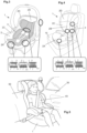
- the child safety seat 1 can be of different types as a function of the age and weight of the baby/child. Specifically, a child safety seat 1 can be a rear facing baby seat, a forward facing baby seat or a booster seat. The child safety seat 1 is generally positioned and secured over a seat 50 of a vehicle/car 30 and it is shaped so as to accommodate a baby/child 40, as shown in Fig. 5 .
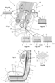
- Fig. 1 is represented a child safety seat 1 according to a first embodiment.
- the baby seat comprises a frame 2, also called chassis or shell, made of a rigid plastic, that represents the skeleton of the child seat 1.
- the frame 2 of Fig. 1 comprises right and left side portions 2C, a backrest portion 2B and a sitting portion 2A. These portions are continuous each other.
- the backrest portion 2B is continuous with the sitting portion 2C and from them two side portions 2C laterally branch, respectively on the right and left sides.
- Each side portion 2C can comprise an armrest portion, indicated in Fig. 1 with the reference number 2C, and a headrest portion 2D.
- the frame 2 is thus a single piece of rigid plastic, on which one or more impact absorbing assemblies 4 are attached.
- the frame 2 is preferably made of a rigid plastic like polypropylene.
- the impact absorbing assembly 4 includes a deformable polymeric layer 5 and an associated honeycomb cellular insert 6 that is contained in the deformable polymeric layer 5.
- the impact absorbing assembly 4 can be arranged on the inner side of the frame 2, thus towards the child area 3 and/or on the outer face of the frame 2, thus facing outside.
- the deformable polymeric layer 5 can be made of a rigid polymer closed-cell foam, when it faces the child area 3. Otherwise, the deformable polymeric layer 5' can be made of rubber or another elastomeric material (not a foam), when it faces outside the child seat.
- the child safety seat 1 can comprise one or impact absorbing assemblies 4. When they are more than one, each of above-mentioned seat portions 2A, 2B, 2C, 2D comprises at least one impact absorbing assembly 4. Alternatively, one single impact absorbing assembly 4 covers the whole frame 2 or a part of it.
- the honeycomb cellular inserts 6 in the impact absorbing assembly 4 can be one or more than one.
- Each honeycomb cellular insert 6 comprises a plurality of open cells 7 that are interconnected each other to form a honeycomb sheet. This honeycomb sheet can be flat or curved.
- Each cell 7 has a longitudinal axis L.
- the cells 7 are interconnected each other so that the longitudinal axes L are outwardly oriented with respect to a surface (inner or outer) of the frame 2.
- Said cells 7 are configured to absorb energy by plastic deformation in response to a longitudinal compressive load applied along said longitudinal axis L.
- plastic deformation means an irreversible deformation of the cell 7.
- the cells 7 are preferably tubes, as shown in Fig. 2A .
- Each tube 7 has sidewall/s 18 and open ends 19. Through said open ends 19 and through the empty space surrounded by the sidewall/s 18 the air can flow.
- Each cell/tube 7 has two edges in correspondence of said opposite ends 19. Said cells/tubes 7 are interconnected each other via their sidewalls 18 so as to form said honeycomb cellular insert 6.
- the sidewall/s 18 of the cell 7 are configured to irreversibly, or substantially irreversibly, buckle on itself/themselves. When the cells 7 are compressed and plastically deform, they absorb a great amount of energy.
- the tubes 7 of Fig 2A have circular cross-sections.
- the cross-section of the cells/tubes 7 can be a square, a hexagon, a non-uniform hexagon, a re-entrant hexagon, a chiral truss, a diamond, a triangle or an arrowhead.
- said tube 7 has upper and lower open bases having a polygonal and/or curved edges.
- the cells/tubes 7 can be welded each other via their sidewalls 18.
- the tubes 7 can be bonded by means of adhesive layers interposed between adjacent sidewalls 18.
- Said adhesive layer is preferably a thermo-active adhesive.
- the tubes 7 are interconnected so as to minimize the gap between adjacent tubes 7.
- the outer diameter of the circular cross-section can range between 2,5 and 10 mm, preferably between 6 and 8 mm, and the wall thickness of said sidewall 14 can range between 0,04 and 0,15 mm. According to these dimensional values, the energy absorption is optimized. Furthermore, these values permit to achieve a very light honeycomb cellular insert 6.
- the honeycomb cellular insert 6 so conceived has a thickness comprised between 5 mm and 30 mm.
- honeycomb cellular insert 6 can have longitudinal axes L inclined with respect to a surface of the frame 2, as shown in Fig. 2 for the honeycomb cellular insert 6 of the sitting portion 2A.
- the honeycomb cellular insert 6 can have cells 7 having longitudinal axes L substantially normal to the surface of the frame, as shown in Fig. 2 for the honeycomb cellular insert 6 of the back rest portion 2B.
- the angle ⁇ comprised between the direction normal N to the inner/outer surface of the frame 2 and the longitudinal axis L of the cells is comprised between 5° and 45°.
- This inclination of the longitudinal axes L makes the honeycomb cellular insert 6 less stiff. Moreover, it allows to absorb more efficiently compressive loads that are not orthogonal to the frame 2.
- Honeycomb cellular inserts 6 having inclined cells are particularly recommended when the honeycomb cellular insert 6 faces toward the child area 3.
- All the longitudinal axes L of the cells 7 are preferably parallel each other.
- the longitudinal axes substantially point towards a common center of curvature.
- the honeycomb cellular insert 6 When the honeycomb cellular insert 6 is curved and the underneath frame 2 is curved, they can have substantially the same curvature. In this way, the cells 7 are normal to the frame 2.
- honeycomb cellular insert 6 When the honeycomb cellular insert 6 is curved and the underneath frame 2 is flat, or vice versa, only some of these cells 7 are normal, or substantially normal, to the inner/outer surface of the frame 2 and all the other cells are inclined as described above.
- the honeycomb cellular insert 6 can be a honeycomb sheet as described above comprising one or more slits. These slits are cuts realized along the thickness direction of the honeycomb sheet that do not pass-through it. Said slits involve only a portion of said honeycomb sheet thickness, preferably at least 50% of it. These slits reduce the initial compressive stress peak.
- the cells 7 of the honeycomb cellular insert 6 are pre-crushed, for reducing the initial compressive stress peak. "Pre-crushing" means that a longitudinal pre-compression of the cells 7 occurred so as to partially or slightly buckle the cells 7.
- the honeycomb cellular insert 6 is laminated with a flexible sheet on one or both sides.
- the flexible sheet so connected to the free edges of the open ends 19 of the cells 7, allows to involve more cells 7 in the progressive plastic buckling.
- the impact absorbing assembly 4 When the impact absorbing assembly 4 is arranged onto the inner face of the frame 2, it comprises a deformable polymeric layer 5, preferably made of a polymeric foam, and one or more honeycomb cellular inserts 6. In this case, the impact absorbing assembly 4 constitutes the inner lining of child safety seat 1.
- the one or more honeycomb cellular inserts 6 can be arranged into or all the way through the deformable polymeric layer 5 as described in detail in the following.
- each portion of the child safety seat 1 comprises one honeycomb cellular insert 6. Consequently, the sitting portion 2A comprises its honeycomb cellular insert 6, the backrest portion 2B comprises its honeycomb cellular insert 6, and the side portions 2C comprise respective honeycomb cellular inserts 6, as shown in Fig. 2 . Alternatively, only some of these portions 2A,2B,2C comprise honeycomb cellular inserts 6, for example only the backrest and sitting portions 2B,2A. Alternatively, the honeycomb cellular insert 6 is one for both these portions 2A,2B and it has a curved shape concordant with the shape of the frame 2.
- honeycomb cellular insert 6 Being the honeycomb cellular insert 6 a sheet, it can be easily inserted in the deformable polymeric layer 5.
- the deformable polymeric layer 5 can be made of a rigid polymer closed-cell foam.
- the polymeric foam is EPP (Expanded PolyPropylene) or EPS (Expanded PolyStyrene).
- the honeycomb cellular insert 6 can be arranged above the deformable polymeric layer 5, so that the deformable polymeric layer 5 is sandwiched between the honeycomb cellular insert 6 and the frame 2, as shown in Fig. 1A .
- the honeycomb cellular insert 6 can be arranged under the deformable polymeric layer 5, so that the honeycomb cellular insert 6 is sandwiched between the deformable polymeric layer 5 and the frame 2, as shown in Fig. 1B .
- the honeycomb cellular insert 6 is sized to fit within the recess 8 of the deformable polymeric layer 5. Substantially, the outer shape of the honeycomb cellular insert 6 matches with the inner shape of the recess 8. In this way, the honeycomb cellular insert 6 is held in the recess 8 of the deformable polymeric layer 5 and, even if a force tends to in-plane compress the insert 6, it remains in place and does not get out the recess 8. This phenomenon can occur in case of an oblique impacts that moves laterally the honeycomb cellular insert 6 with respect to the deformable polymeric layer 5.
- the recess 8 of the embodiments of Figs. 1A and 1B is a pocket 8A of the deformable polymeric layer 5.
- the honeycomb cellular insert 6 is recessed and confined in the pocket 8A of the deformable polymeric layer 5 so as to be in contact with the frame 2, as shown in Fig. 1B , or so as to face toward the child area 3, as shown in Fig. 1A .
- the pocket 8A prevents a global translation of the honeycomb cellular insert 6 relative to the deformable polymeric layer 5.
- the impact absorbing assembly 4 can be easily adapted to any shape of the frame 2, indeed the deformable polymeric layer 5 is easier to mould into complex shapes.
- the honeycomb cellular insert 6 is arranged under the deformable polymeric layer 5, as shown in Fig. 1B , the deformable polymeric layer 5 allow to spread the energy of an impact over a wider area of the honeycomb cellular insert 6.
- the deformable polymeric layer 5 can comprise one or more pass-through apertures 8B, that are like passing holes or cut-offs of the deformable polymeric layer 5, in which corresponding honeycomb cellular inserts 6 are inserted, as shown in Fig. 1C .
- the thickness of the honeycomb cellular inserts 6 is substantially the same of the deformable polymeric layer 5 and the honeycomb cellular inserts 6 and the deformable polymeric layer 5 are co-planar on both sides.
- the child safety seat 1 comprises zones wherein the performances in term of energy absorption of the impact absorbing assembly 1 are improved.
- the portions 2A,2B,2C of the child safety seat 1 can comprise any one of the above described arrangements of honeycomb cellular insert 6 with respect to the deformable polymeric layer 5.
- Fig. 2 is represented a child seat 1 wherein the honeycomb cellular inserts 6 are recessed from inside in the deformable polymeric layer 5, but any other arrangement of Figs. 1A-1C can be used as alternatives.
- the surface of contact between the deformable polymeric layer 5 and the honeycomb cellular insert 6 can comprise a film or coating which prevents penetration of the honeycomb cellular insert 6 into the deformable polymeric layer 5 and facilitates a relative sliding between the honeycomb cellular insert 6 and the deformable polymeric layer 5.
- This film or coating is stiffer than the deformable polymeric layer 5, so as to allow said sliding and to avoid said penetration.
- the impact absorbing assembly 4 is attached or secured to the frame 2.
- said connection with the frame 2 of the deformable polymeric layer 5 is realized with an adhesive layer or with glue.
- the deformable polymeric layer 5 can be attached to the frame with screws.
- the honeycomb cellular insert 6 is fastened to the frame 2 through cable ties.
- the deformable polymeric layer 5 and the frame 2 are preferably holed as shown in Fig. 2 , so as to allow an air transit.
- An airflow can transit through the holes 14 of the deformable polymeric layer 5 and through the open cells 7 of the honeycomb cellular insert 6. Said airflow can also flow through the permeable seat cover 10, so as to cross the whole thickness of the seat 1.
- the holes 14 represented in Fig. 2 are arranged in the backrest portion 2A, but they can be arranged in any other portion of the child seat 1.
- the holes 14 of the deformable polymeric layer 5 lie in correspondence of the area wherein the honeycomb cellular insert 6 is arranged.
- the thickness of the honeycomb cellular insert 6 is comprised between 30% and 100% of the thickness of the deformable polymeric layer 5, so as to improve the energy absorption.
- the deformable polymeric layer 5 is compressed and the honeycomb cellular insert 6 deforms absorbing a greater quantity of energy with respect to the deformable polymeric layer 5.
- a very efficient energy absorbing pad is obtained.
- This impact absorbing assembly 4 is capable to fit with all regulations in term of safety for child seats for vehicles.
- the honeycomb cellular insert 6 continues to be contained in the deformable polymeric layer 5 even if compressed by the impact.
- FIGs. 1-4 show an impact absorbing assembly 4 having a deformable polymeric layer 5 arranged in the inner surface of the frame 2, the same type of impact absorbing assembly 4 can be also arranged on the outer surface of the frame 2.
- the seat cover 10 can cover the entire impact absorbing assembly 4 or, if the impact absorbing assemblies 4 of the seat 1 are more than one, each impact absorbing assembly 4 is covered by its own seat cover 10.
- the seat cover 10 can also cover a part of the frame 2.
- the seat cover 10 is preferably made of a synthetic fabric or textile.
- the seat cover 10 can also comprise a soft permeable padding to make the impact absorbing assembly 4 more comfortable.
- the seat cover 10 wraps completely the block composed by one honeycomb cellular insert 6 and one deformable polymeric layer 5, so as to realize a cushion (not shown).
- the inner lining of the child safety seat 1 can be composed by a plurality of interchangeable cushions so conceived.
- the cushion can be selected as a function of the weight/height of the child.
- each cushion is constituted by the seat cover 10, the honeycomb cellular insert 6 and the soft foam layer 12.
- the impact absorbing assembly 4 (the cushion) so conceived is connected to the frame 2 through reversible connecting means, like for example snap buttons or similar devices.
- the child safety seat 1 so realized is modular and with a single frame 2 and a different types of cushions, several customizable versions of the seat 1 can be realized for different needs in term of weight/height.
- the impact absorbing assembly 4 When the impact absorbing assembly 4 is arranged on the outer face of the frame 2, so as to face outwardly as shown in Fig. 1D , it comprises a deformable polymeric shell 5', that represents the deformable polymeric layer 5, and a honeycomb cellular insert 6.
- the honeycomb cellular insert 6 is surrounded by the deformable polymeric shell 5' so that only one side of the honeycomb cellular insert 6 remains in contact with the frame 2.
- the cells 7 of the honeycomb cellular insert 6 have parallel longitudinal axes L and are orthogonal to the outer surface of the frame 2 or inclined with respect to it, as described above.
- the deformable polymeric shell 5' is preferably made of an elastomeric material, like rubber, so as to be resilient.
- the deformable polymeric shell 5' comprises an inner chamber fitting with the outer shape of the honeycomb cellular insert 6.
- the honeycomb cellular insert 6 is accommodated in said inner chamber before fixing the deformable polymeric shell 5' to the frame 2.
- the deformable polymeric shell 5' is firmly attached to the frame 2 so as to maintain the honeycomb cellular insert 6 in contact with the outer surface of the frame 2.
- the open ends belonging to the same side of the honeycomb cellular insert 6 are thus in contact with said outer surface of the frame 2.
- the outer impact absorbing assembly 4 so conceived works like an external bumper for the child safety seat 1.
- the deformable polymeric shell 5' flexes and the underlying honeycomb cellular insert 6 plastically deforms. In this way, the external impact absorbing assembly 4 absorbs a very high quantity of the impact energy transmitted by the vehicle to the child seat 1.
- the impact absorbing assembly 4 arranged on the outer face of the frame 2 with a honeycomb cellular insert 6 surrounded by the deformable polymeric shell 5' is not an alternative to the impact absorbing assembly 4 arranged on the inner face of the frame 2. Indeed, a synergic protective effect for the child safety seat 1 can be achieved if both inner and outer impact energy absorbing assemblies 4 are used.
- the child safety seat 1 can also comprise a base 15 as shown in Fig. 2 .
- the base 15 can be the lower part of the child safety seat 1 remaining attached to the vehicle 30, even if the upper part is detached for different needs.
- the base 15 is configured to be connectable to the frame 2 of the child safety seat 1.
- the base 15 also comprises a honeycomb cellular insert 6 that is arranged on a bulk portion of the base so as to remain in contact with the frame 2. This honeycomb cellular insert 6 allows to absorb certain sudden movements of the frame 2 with respect to the vehicle 30. If the frame 2 inclines with respect to the base 15, the honeycomb cellular insert 6 of the base deforms, absorbing the energy of this compression.
- the child safety seat can comprise a comfort cushion 11.
- This comfort cushion 11 is a detachable insert shaped so as to be arrangeable in the child safety seat 21, between the impact absorbing assembly 2 and the child (child area 3), as shown in Fig. 1,2 and 3 .
- This comfort cushion 11 can be a traditional comfort cushion made of a soft permeable foam or an improved comfort cushion 11 as shown in Figs. 1, 1E and 2 .
- This improved comfort cushion 11 comprises a soft foam layer 12 and a honeycomb cellular layer 13.
- the honeycomb cellular layer 13 is a thin honeycomb sheet that is structurally similar to the above-described honeycomb cellular insert 6.
- the honeycomb cellular layer 13 can be thinner than the honeycomb cellular insert 6.
- the honeycomb cellular layer 13 can comprise cells having a wider cross-sectional area with respect to that of the honeycomb cellular insert 6. Consequently, the honeycomb cellular layer 13 is flexible and can be easily folded for inserting/removing the comfort cushion 11 in/from the child safety seat 1.
- the honeycomb cellular layer 13 is attached to the soft foam layer 12 through an adhesive.
- the soft foam layer 12 is preferably arranged so as to face towards the child area 3.
- the pack constituted by the soft foam layer 12 and the honeycomb cellular layer 13 is wrapped by a fabric or textile.
- the comfort cushion 11 makes the child seat 1 more comfortable. Furthermore, this comfort cushion 11 is removable and thus washable.
- the comfort cushion 11 with the honeycomb cellular layer 13 also improves the energy absorption in case of an impact.
- the comfort cushion 11 also allows to customize the inner side of the child safety seat 1 (the child area 3). Indeed, through comfort cushions 11 having different sizes, shapes and internal characteristics (e.g. a different thickness of the honeycomb cellular layer 13), the same child safety seat 1 can be adapted to an infant, a young child or an older child, by simply modifying the comfort cushion 11.
- FIGs. 3 and 4 are schematically represented other two types of child safety seats 1 according to this invention.
- Fig. 3 is represented a child safety seat 1 for enfant.
- Fig. 4 is represented a child safety seat 1 for children that are older than that using the child safety seat 1 of Fig. 1 .
- the same considerations described above for the child safety seat 1 of Figs. 1 and 2 apply to the child safety seats of Figs. 3 and 4 .
Landscapes
- Engineering & Computer Science (AREA)
- Health & Medical Sciences (AREA)
- Child & Adolescent Psychology (AREA)
- General Health & Medical Sciences (AREA)
- Aviation & Aerospace Engineering (AREA)
- Transportation (AREA)
- Mechanical Engineering (AREA)
- Seats For Vehicles (AREA)
Claims (15)
- Kindersicherheitssitz (1) für ein Fahrzeug (30), umfassend:- einen Rahmen (2), der so geformt ist, dass er ein Kind (40) in einem Kinderbereich (3) aufnehmen kann, wobei der Rahmen (2) einen Sitzabschnitt (2A), einen Rückenlehnenabschnitt (2B) und Seitenabschnitte (2C) umfasst;- mindestens eine Aufprallabsorptionsanordnung (4), die mit dem Rahmen (2) verbunden ist und umfasst:- eine verformbare Polymerschicht (5);- mindestens einen wabenförmigen Zelleinsatz (6), der mit der verformbaren Polymerschicht (5) verbunden ist;wobei der mindestens eine wabenförmige Zelleinsatz (6) eine Vielzahl von offenen Zellen (7) mit Längsachsen (L) umfasst, die aus einer Innen-/Außenfläche des Rahmens (2) herausragen, wobei die Zellen (7) so konfiguriert sind, dass sie als Reaktion auf eine auf die Zellen (7) ausgeübte Längsdruckbelastung Energie durch plastische Verformung absorbieren; unddadurch gekennzeichnet, dass die verformbare Polymerschicht (5) so geformt ist, dass sie den mindestens einen wabenförmigen Zelleinsatz (6) enthält.
- Kindersicherheitssitz (1) nach Anspruch 1, wobei die Längsachsen (L) zumindest teilweise senkrecht (N) zur Innen- oder Außenfläche des Rahmens (2) verlaufen.
- Kindersicherheitssitz (1) nach Anspruch 1 oder 2, wobei die Längsachsen (L) zumindest teilweise um einen Winkel zwischen 5° und 45° gegenüber einer senkrecht (N) zur Innen- oder Außenfläche des Rahmens (2) verlaufenden Richtung geneigt sind.
- Kindersicherheitssitz (1) nach einem der vorhergehenden Ansprüche, wobei die Aufprallabsorptionsvorrichtung (4) zum Kinderbereich (3) weist.
- Kindersicherheitssitz (1) nach Anspruch 4, wobei der wabenförmige Einsatz (6) so bemessen ist, dass er in eine Aussparung (8) der verformbaren Polymerschicht (5) passt.
- Kindersicherheitssitz (1) nach Anspruch 5, wobei der mindestens eine Wabenzelleneinsatz (6) zwischen der verformbaren Polymerschicht (5) und dem Rahmen (2) angeordnet ist oder alternativ die verformbare Polymerschicht (5) zwischen dem mindestens einen Wabenzelleneinsatz (6) und dem Rahmen (2) angeordnet ist.
- Kindersicherheitssitz (1) nach Anspruch 6, wobei die Aussparung (8) eine Tasche (8A) ist, in der der Wabenzelleneinsatz (6) untergebracht ist.
- Kindersicherheitssitz (1) nach Anspruch 5, wobei die Aussparung (8) eine Durchgangsöffnung (8B) in der verformbaren Polymerschicht (5) ist, in der der Wabenzelleneinsatz (6) so angeordnet ist, dass die verformbare Polymerschicht (5) und der Wabenzelleneinsatz (6) bündig sind.
- Kindersicherheitssitz (1) nach einem der Ansprüche 4 bis 8, wobei die verformbare Polymerschicht (5) und der Rahmen (2) eine Vielzahl von Durchgangslöchern (14) aufweisen, die in Übereinstimmung mit dem wabenförmigen Zelleinsatz (6) angeordnet sind.
- Kindersicherheitssitz (1) nach einem der Ansprüche 5 bis 9, wobei die verformbare Polymerschicht (5) ein Teil des Kindersitzes ist, auf dem das Kind sitzt, der vorzugsweise aus einem starren Polymerschaum mit geschlossenen Zellen besteht.
- Kindersicherheitssitz (1) nach einem der vorhergehenden Ansprüche, der außerdem einen atmungsaktiven Sitzbezug (10) aufweist, der so konfiguriert ist, dass er zumindest einen Teil des Rahmens (2) und der Aufprallabsorptionsanordnung (4) bedeckt, wobei der Sitzbezug (10) vorzugsweise aus einem Stoff besteht.
- Kindersicherheitssitz (1) nach einem der vorhergehenden Ansprüche, wobei der mindestens eine Wabenzelleneinsatz (6) in Übereinstimmung mit dem Sitzabschnitt (2A) angeordnet ist, so dass er unterhalb des Kindes (40) liegt, und/oder in Übereinstimmung mit dem Rückenlehnenabschnitt (2B), so dass er hinter der Wirbelsäule und/oder dem Kopf des Kindes (40) liegt, und/oder in Übereinstimmung mit den Seitenabschnitten (2C), so dass er neben den Schultern und/oder Hüften und/oder dem Kopf des Kindes (40) liegt.
- Kindersicherheitssitz (1) nach einem der vorhergehenden Ansprüche, wobei die Seitenteile (2C) des Rahmens (2) zwei seitliche Kopfstützteile (2D) umfassen und, wenn die Aufprallabsorptionsanordnung (4) in Übereinstimmung mit jedem der beiden seitlichen Kopfstützteile (2D) des Rahmens (2) angeordnet ist, so dass sie nach außen weist, die verformbare Polymerschicht (5) so geformt ist, dass sie den mindestens einen Wabenzelleneinsatz (6) umgibt, so dass der Wabenzelleneinsatz (6) in Kontakt mit einer Außenfläche des Rahmens (2) bleibt und die verformbare Polymerschicht (5) nach außen von der Außenfläche des Rahmens (2) vorsteht.
- Kindersicherheitssitz (1) nach einem der vorhergehenden Ansprüche, der außerdem eine Basis (15) umfasst, die mit dem Rahmen (2) verbindbar ist, wobei die Basis (15) einen Wabenzelleneinsatz (6) umfasst.
- Kindersicherheitssitz (1) nach einem der vorhergehenden Ansprüche, umfassend ein Komfortkissen (11), das zwischen der Aufprallabsorptionsanordnung (4) und dem Kinderbereich (3) angeordnet ist, wobei das Komfortkissen (11) eine in Richtung des Kinderbereichs (3) angeordnete Weichschaumschicht (12) und eine zwischen der Weichschaumschicht (12) und der Aufprallabsorptionsanordnung (4) angeordnete Wabenzellschicht (13) umfasst.
Applications Claiming Priority (2)
| Application Number | Priority Date | Filing Date | Title |
|---|---|---|---|
| EP20020613.4A EP4011691A1 (de) | 2020-12-14 | 2020-12-14 | Kindersicherheitssitz |
| PCT/IB2021/061618 WO2022130159A1 (en) | 2020-12-14 | 2021-12-13 | Child safety seat |
Publications (3)
| Publication Number | Publication Date |
|---|---|
| EP4259482A1 EP4259482A1 (de) | 2023-10-18 |
| EP4259482B1 true EP4259482B1 (de) | 2025-02-19 |
| EP4259482C0 EP4259482C0 (de) | 2025-02-19 |
Family
ID=73854514
Family Applications (2)
| Application Number | Title | Priority Date | Filing Date |
|---|---|---|---|
| EP20020613.4A Pending EP4011691A1 (de) | 2020-12-14 | 2020-12-14 | Kindersicherheitssitz |
| EP21835845.5A Active EP4259482B1 (de) | 2020-12-14 | 2021-12-13 | Kindersicherheitssitz |
Family Applications Before (1)
| Application Number | Title | Priority Date | Filing Date |
|---|---|---|---|
| EP20020613.4A Pending EP4011691A1 (de) | 2020-12-14 | 2020-12-14 | Kindersicherheitssitz |
Country Status (3)
| Country | Link |
|---|---|
| US (1) | US12427897B2 (de) |
| EP (2) | EP4011691A1 (de) |
| WO (1) | WO2022130159A1 (de) |
Family Cites Families (19)
| Publication number | Priority date | Publication date | Assignee | Title |
|---|---|---|---|---|
| US4265484A (en) * | 1979-05-10 | 1981-05-05 | The Goodyear Tire & Rubber Company | Reinforced foamed body support member |
| US5649721A (en) * | 1995-01-20 | 1997-07-22 | The Boeing Co. | Impact protection apparatus |
| US6245408B1 (en) * | 1999-05-19 | 2001-06-12 | Hexcel Corporation | Honeycomb core with controlled crush properties |
| DE202006010876U1 (de) * | 2006-07-10 | 2006-09-28 | Takata-Petri Ag | Vorrichtung zur Energieabsorption |
| NL1034678C2 (nl) * | 2007-11-13 | 2009-05-14 | Maxi Miliaan Bv | Voertuigstoel alsmede een steun geschikt voor in een voertuig. |
| US7744154B2 (en) * | 2008-07-30 | 2010-06-29 | Cosco Management, Inc. | Energy-dissipation system |
| US8226162B2 (en) * | 2009-09-11 | 2012-07-24 | Campbell Corey A | Child safety seat |
| AU2011200689A1 (en) * | 2010-02-18 | 2011-09-01 | Britax Childcare Pty Ltd | Improvements relating to vehicle child restraints |
| US8348337B2 (en) * | 2010-03-17 | 2013-01-08 | Britax Child Safety, Inc. | Child safety seat with energy absorbing apparatus |
| US9221366B2 (en) * | 2011-06-02 | 2015-12-29 | Dorel Juvenile Group, Inc. | Energy-dissipation system |
| US8998318B2 (en) * | 2011-08-18 | 2015-04-07 | Cosco Management, Inc. | Child restraint with tiltable juvenile seat |
| USRE47971E1 (en) * | 2012-06-01 | 2020-05-05 | Dorel Juvenile Group, Inc. | Energy-dissipation system |
| US10220734B2 (en) * | 2013-03-05 | 2019-03-05 | Pidyon Controls Inc. | Car seat |
| CA2936917C (en) * | 2015-07-23 | 2018-05-22 | Dorel Juvenile Group, Inc. | Child restraint with energy management system |
| AU2017279736B2 (en) * | 2016-12-23 | 2023-12-14 | Britax Childcare Pty Ltd | Impact energy absorbing device |
| US11235687B2 (en) * | 2018-07-05 | 2022-02-01 | Britax Child Safety Inc. | Multi-functional energy absorber |
| AU2020201572B2 (en) * | 2019-03-13 | 2021-11-25 | Britax Child Safety, Inc. | Child safety seat |
| DE102020116926A1 (de) * | 2020-02-03 | 2021-08-05 | Osann Gmbh | Kindersitz |
| FR3136413A1 (fr) * | 2022-06-10 | 2023-12-15 | Jdsa Distribution | Dispositif pour le transport d’un enfant |
-
2020
- 2020-12-14 EP EP20020613.4A patent/EP4011691A1/de active Pending
-
2021
- 2021-12-13 WO PCT/IB2021/061618 patent/WO2022130159A1/en not_active Ceased
- 2021-12-13 EP EP21835845.5A patent/EP4259482B1/de active Active
- 2021-12-13 US US18/255,056 patent/US12427897B2/en active Active
Also Published As
| Publication number | Publication date |
|---|---|
| US12427897B2 (en) | 2025-09-30 |
| EP4011691A1 (de) | 2022-06-15 |
| US20240051440A1 (en) | 2024-02-15 |
| EP4259482C0 (de) | 2025-02-19 |
| WO2022130159A1 (en) | 2022-06-23 |
| EP4259482A1 (de) | 2023-10-18 |
Similar Documents
| Publication | Publication Date | Title |
|---|---|---|
| KR101492410B1 (ko) | 시트 쿠션 구조물 | |
| US10500990B2 (en) | Car seat | |
| CN105163978B (zh) | 车辆座椅 | |
| US9708067B2 (en) | Seat cushion for use by airline passengers | |
| JP6078858B2 (ja) | チャイルド・シート向けの側面衝撃保護 | |
| CN101827537A (zh) | 用于冲击保护的可压缩衬里 | |
| EP3663127B1 (de) | Feuerfeste pufferstruktur, stützkissenvorrichtung und sicherheitssitz damit | |
| US20190061853A1 (en) | Bicycle Saddle | |
| EP4259482B1 (de) | Kindersicherheitssitz | |
| ES2936016T3 (es) | Un asiento de vehículo | |
| EP3634854B1 (de) | Sitzkissen für fluglinienpassagiere | |
| US11584468B2 (en) | Bicycle saddle | |
| US12083938B2 (en) | Off-road racing vehicle seat | |
| JP4884700B2 (ja) | 車両用シート | |
| JP3171971U (ja) | 全包覆軽量タイプの幼児安全椅子 | |
| JPH0565084A (ja) | 車両シートの背もたれ |
Legal Events
| Date | Code | Title | Description |
|---|---|---|---|
| STAA | Information on the status of an ep patent application or granted ep patent |
Free format text: STATUS: UNKNOWN |
|
| STAA | Information on the status of an ep patent application or granted ep patent |
Free format text: STATUS: THE INTERNATIONAL PUBLICATION HAS BEEN MADE |
|
| PUAI | Public reference made under article 153(3) epc to a published international application that has entered the european phase |
Free format text: ORIGINAL CODE: 0009012 |
|
| STAA | Information on the status of an ep patent application or granted ep patent |
Free format text: STATUS: REQUEST FOR EXAMINATION WAS MADE |
|
| 17P | Request for examination filed |
Effective date: 20230710 |
|
| AK | Designated contracting states |
Kind code of ref document: A1 Designated state(s): AL AT BE BG CH CY CZ DE DK EE ES FI FR GB GR HR HU IE IS IT LI LT LU LV MC MK MT NL NO PL PT RO RS SE SI SK SM TR |
|
| DAV | Request for validation of the european patent (deleted) | ||
| DAX | Request for extension of the european patent (deleted) | ||
| GRAP | Despatch of communication of intention to grant a patent |
Free format text: ORIGINAL CODE: EPIDOSNIGR1 |
|
| STAA | Information on the status of an ep patent application or granted ep patent |
Free format text: STATUS: GRANT OF PATENT IS INTENDED |
|
| INTG | Intention to grant announced |
Effective date: 20240926 |
|
| GRAS | Grant fee paid |
Free format text: ORIGINAL CODE: EPIDOSNIGR3 |
|
| GRAA | (expected) grant |
Free format text: ORIGINAL CODE: 0009210 |
|
| STAA | Information on the status of an ep patent application or granted ep patent |
Free format text: STATUS: THE PATENT HAS BEEN GRANTED |
|
| AK | Designated contracting states |
Kind code of ref document: B1 Designated state(s): AL AT BE BG CH CY CZ DE DK EE ES FI FR GB GR HR HU IE IS IT LI LT LU LV MC MK MT NL NO PL PT RO RS SE SI SK SM TR |
|
| REG | Reference to a national code |
Ref country code: GB Ref legal event code: FG4D |
|
| REG | Reference to a national code |
Ref country code: CH Ref legal event code: EP |
|
| REG | Reference to a national code |
Ref country code: DE Ref legal event code: R096 Ref document number: 602021026504 Country of ref document: DE |
|
| REG | Reference to a national code |
Ref country code: IE Ref legal event code: FG4D |
|
| U01 | Request for unitary effect filed |
Effective date: 20250310 |
|
| U07 | Unitary effect registered |
Designated state(s): AT BE BG DE DK EE FI FR IT LT LU LV MT NL PT RO SE SI Effective date: 20250318 |
|
| PG25 | Lapsed in a contracting state [announced via postgrant information from national office to epo] |
Ref country code: RS Free format text: LAPSE BECAUSE OF FAILURE TO SUBMIT A TRANSLATION OF THE DESCRIPTION OR TO PAY THE FEE WITHIN THE PRESCRIBED TIME-LIMIT Effective date: 20250519 |
|
| PG25 | Lapsed in a contracting state [announced via postgrant information from national office to epo] |
Ref country code: PL Free format text: LAPSE BECAUSE OF FAILURE TO SUBMIT A TRANSLATION OF THE DESCRIPTION OR TO PAY THE FEE WITHIN THE PRESCRIBED TIME-LIMIT Effective date: 20250219 |
|
| PG25 | Lapsed in a contracting state [announced via postgrant information from national office to epo] |
Ref country code: ES Free format text: LAPSE BECAUSE OF FAILURE TO SUBMIT A TRANSLATION OF THE DESCRIPTION OR TO PAY THE FEE WITHIN THE PRESCRIBED TIME-LIMIT Effective date: 20250219 |
|
| PG25 | Lapsed in a contracting state [announced via postgrant information from national office to epo] |
Ref country code: IS Free format text: LAPSE BECAUSE OF FAILURE TO SUBMIT A TRANSLATION OF THE DESCRIPTION OR TO PAY THE FEE WITHIN THE PRESCRIBED TIME-LIMIT Effective date: 20250619 Ref country code: NO Free format text: LAPSE BECAUSE OF FAILURE TO SUBMIT A TRANSLATION OF THE DESCRIPTION OR TO PAY THE FEE WITHIN THE PRESCRIBED TIME-LIMIT Effective date: 20250519 |
|
| PG25 | Lapsed in a contracting state [announced via postgrant information from national office to epo] |
Ref country code: HR Free format text: LAPSE BECAUSE OF FAILURE TO SUBMIT A TRANSLATION OF THE DESCRIPTION OR TO PAY THE FEE WITHIN THE PRESCRIBED TIME-LIMIT Effective date: 20250219 |
|
| PG25 | Lapsed in a contracting state [announced via postgrant information from national office to epo] |
Ref country code: GR Free format text: LAPSE BECAUSE OF FAILURE TO SUBMIT A TRANSLATION OF THE DESCRIPTION OR TO PAY THE FEE WITHIN THE PRESCRIBED TIME-LIMIT Effective date: 20250520 |
|
| PG25 | Lapsed in a contracting state [announced via postgrant information from national office to epo] |
Ref country code: SM Free format text: LAPSE BECAUSE OF FAILURE TO SUBMIT A TRANSLATION OF THE DESCRIPTION OR TO PAY THE FEE WITHIN THE PRESCRIBED TIME-LIMIT Effective date: 20250219 |
|
| PG25 | Lapsed in a contracting state [announced via postgrant information from national office to epo] |
Ref country code: CZ Free format text: LAPSE BECAUSE OF FAILURE TO SUBMIT A TRANSLATION OF THE DESCRIPTION OR TO PAY THE FEE WITHIN THE PRESCRIBED TIME-LIMIT Effective date: 20250219 |
|
| PG25 | Lapsed in a contracting state [announced via postgrant information from national office to epo] |
Ref country code: SK Free format text: LAPSE BECAUSE OF FAILURE TO SUBMIT A TRANSLATION OF THE DESCRIPTION OR TO PAY THE FEE WITHIN THE PRESCRIBED TIME-LIMIT Effective date: 20250219 |
|
| PLBE | No opposition filed within time limit |
Free format text: ORIGINAL CODE: 0009261 |
|
| STAA | Information on the status of an ep patent application or granted ep patent |
Free format text: STATUS: NO OPPOSITION FILED WITHIN TIME LIMIT |
|
| 26N | No opposition filed |
Effective date: 20251120 |
|
| U20 | Renewal fee for the european patent with unitary effect paid |
Year of fee payment: 5 Effective date: 20251219 |