EP4257995A2 - Procédé de commande d'un système d'alimentation électrique sans coupure et système d'alimentation électrique associé - Google Patents
Procédé de commande d'un système d'alimentation électrique sans coupure et système d'alimentation électrique associé Download PDFInfo
- Publication number
- EP4257995A2 EP4257995A2 EP23183530.7A EP23183530A EP4257995A2 EP 4257995 A2 EP4257995 A2 EP 4257995A2 EP 23183530 A EP23183530 A EP 23183530A EP 4257995 A2 EP4257995 A2 EP 4257995A2
- Authority
- EP
- European Patent Office
- Prior art keywords
- charging
- unit
- accumulator module
- basic unit
- accumulator
- Prior art date
- Legal status (The legal status is an assumption and is not a legal conclusion. Google has not performed a legal analysis and makes no representation as to the accuracy of the status listed.)
- Pending
Links
- 238000000034 method Methods 0.000 title claims abstract description 89
- 238000007600 charging Methods 0.000 claims abstract description 166
- 238000012544 monitoring process Methods 0.000 claims abstract description 57
- 238000007599 discharging Methods 0.000 claims abstract description 49
- 239000008186 active pharmaceutical agent Substances 0.000 claims description 19
- 238000011156 evaluation Methods 0.000 claims description 5
- 230000000007 visual effect Effects 0.000 claims description 4
- 230000005540 biological transmission Effects 0.000 abstract description 9
- 230000001276 controlling effect Effects 0.000 description 10
- 238000004891 communication Methods 0.000 description 5
- 238000010280 constant potential charging Methods 0.000 description 4
- 230000001419 dependent effect Effects 0.000 description 3
- HBBGRARXTFLTSG-UHFFFAOYSA-N Lithium ion Chemical compound [Li+] HBBGRARXTFLTSG-UHFFFAOYSA-N 0.000 description 2
- 230000033228 biological regulation Effects 0.000 description 2
- 238000010277 constant-current charging Methods 0.000 description 2
- 238000010281 constant-current constant-voltage charging Methods 0.000 description 2
- 238000009434 installation Methods 0.000 description 2
- 229910001416 lithium ion Inorganic materials 0.000 description 2
- 230000007257 malfunction Effects 0.000 description 2
- 230000001105 regulatory effect Effects 0.000 description 2
- 238000012546 transfer Methods 0.000 description 2
- 230000032683 aging Effects 0.000 description 1
- 230000009286 beneficial effect Effects 0.000 description 1
- 230000003139 buffering effect Effects 0.000 description 1
- 230000007423 decrease Effects 0.000 description 1
- 238000004146 energy storage Methods 0.000 description 1
- 239000000463 material Substances 0.000 description 1
- 238000005259 measurement Methods 0.000 description 1
- 238000012545 processing Methods 0.000 description 1
- 230000035882 stress Effects 0.000 description 1
- 239000000126 substance Substances 0.000 description 1
Images
Classifications
-
- H—ELECTRICITY
- H02—GENERATION; CONVERSION OR DISTRIBUTION OF ELECTRIC POWER
- H02J—CIRCUIT ARRANGEMENTS OR SYSTEMS FOR SUPPLYING OR DISTRIBUTING ELECTRIC POWER; SYSTEMS FOR STORING ELECTRIC ENERGY
- H02J9/00—Circuit arrangements for emergency or stand-by power supply, e.g. for emergency lighting
- H02J9/04—Circuit arrangements for emergency or stand-by power supply, e.g. for emergency lighting in which the distribution system is disconnected from the normal source and connected to a standby source
- H02J9/06—Circuit arrangements for emergency or stand-by power supply, e.g. for emergency lighting in which the distribution system is disconnected from the normal source and connected to a standby source with automatic change-over, e.g. UPS systems
- H02J9/061—Circuit arrangements for emergency or stand-by power supply, e.g. for emergency lighting in which the distribution system is disconnected from the normal source and connected to a standby source with automatic change-over, e.g. UPS systems for DC powered loads
-
- G—PHYSICS
- G01—MEASURING; TESTING
- G01R—MEASURING ELECTRIC VARIABLES; MEASURING MAGNETIC VARIABLES
- G01R31/00—Arrangements for testing electric properties; Arrangements for locating electric faults; Arrangements for electrical testing characterised by what is being tested not provided for elsewhere
- G01R31/36—Arrangements for testing, measuring or monitoring the electrical condition of accumulators or electric batteries, e.g. capacity or state of charge [SoC]
- G01R31/382—Arrangements for monitoring battery or accumulator variables, e.g. SoC
- G01R31/3835—Arrangements for monitoring battery or accumulator variables, e.g. SoC involving only voltage measurements
-
- H—ELECTRICITY
- H01—ELECTRIC ELEMENTS
- H01M—PROCESSES OR MEANS, e.g. BATTERIES, FOR THE DIRECT CONVERSION OF CHEMICAL ENERGY INTO ELECTRICAL ENERGY
- H01M10/00—Secondary cells; Manufacture thereof
- H01M10/42—Methods or arrangements for servicing or maintenance of secondary cells or secondary half-cells
- H01M10/425—Structural combination with electronic components, e.g. electronic circuits integrated to the outside of the casing
- H01M10/4257—Smart batteries, e.g. electronic circuits inside the housing of the cells or batteries
Definitions
- the present invention generally relates to uninterruptible power supply systems or so-called uninterruptable power supply or UPS systems.
- the present invention relates to a method for controlling an uninterruptible power supply system and an associated uninterruptible power supply system for carrying out the method according to the invention.
- the uninterruptible power supply system includes at least one basic unit and at least one accumulator module with a monitoring unit.
- the basic unit has at least one charging unit and a control unit for controlling the charging unit and can be mounted spatially separately from the at least one accumulator module.
- UPS uninterruptible power supply systems
- UPS uninterruptable power supply
- An uninterruptible power supply system typically consists of a basic unit and one or more accumulator modules, which usually includes an accumulator for energy storage.
- An accumulator is a rechargeable storage device for electrical energy, typically based on an electrochemical system, through which electrical energy is converted into chemical (storage) energy when charging and converted back into electrical energy when discharging.
- Types of accumulators are usually named after the materials used.
- Well-known types of accumulators are, for example, lithium-ion accumulators, lead accumulators, etc.
- the term rechargeable battery or battery can also be used synonymously for the term accumulator or battery for short.
- the accumulator module can also include a monitoring unit - such as from the document DE 198 34 740 A1 known.
- This monitoring unit can be used to monitor the battery and can determine operating parameters of the battery (e.g. battery temperature, battery voltage, etc.) as well as characteristic battery parameters (e.g. final charge voltage, maximum charging current, temperature dependence of the final charge voltage, final discharge voltage, accumulator type, accumulator size, etc.). and save.
- the basic unit of the uninterruptible power supply which is connected on the input side to the power supply and on the output side to a load to be supplied, comprises at least one charging unit or a charge controller and a control unit.
- the charging unit or the charge controller is used to charge the accumulator module or modules and to implement a charging or discharging process.
- the control unit is used to control the charging unit or the charge controller.
- the basic unit has a connection unit through which the at least one accumulator module can be connected to the load in the event of a fault or failure of the energy supply network.
- the basic unit and the battery module or battery modules can be installed spatially separated from one another.
- the basic unit with charging unit, control unit and connection unit is located, for example, in a housing that is mounted on a top-hat rail in a control cabinet, for example.
- the associated accumulator module or modules can, for example, be attached to the bottom of the control cabinet or another location because of the lower temperature level.
- the uninterruptible power supply Without disruptions to the energy supply, electrical energy is passed on from the uninterruptible power supply to both the connected load and to the at least one associated battery module - i.e. the battery is charged.
- the at least one accumulator module of the uninterruptible power supply is connected to the load and begins to discharge towards the load in order to maintain the electrical power supply.
- the energy supply network returns to its normal state, the load and the at least one accumulator module are in turn supplied with electrical energy. This means that with an uninterruptible power supply, the at least one battery is charged during normal operation of the energy supply network and discharged in the event of a fault.
- IU charging process or constant current constant voltage process (CCCV process) is often used when charging batteries that are commonly used today (e.g. lead accumulator, lithium-ion battery, etc.), which is the so-called constant current the constant voltage charging process.
- CCCV process constant current constant voltage process
- the battery In the first phase of the charging process, the battery is charged with a constant current. The voltage at the battery terminals increases as the charge level increases.
- end of charge voltage is reached on the battery, the basic unit switches from current to voltage regulation.
- the second charging phase charging continues at a constant voltage, with the voltage at the battery terminals being kept at a constant value.
- the charging current automatically decreases continuously until a predetermined minimum value is reached, which can be used as a criterion for terminating the charging process, for example by the basic unit.
- the discharging process should be terminated by the basic unit when a so-called final discharge voltage is reached or falls below - another characteristic value of the respective battery.
- the final discharge voltage is one fixed voltage up to which the battery can be discharged and depends on the respective battery type.
- the basic unit in which the control unit and charging unit are mounted for controlling and regulating the charging and discharging process, is often spatially separated from the accumulator or accumulators of the uninterruptible power supply system.
- appropriate data e.g. battery parameters, current values of operating parameters such as temperature, voltage, etc.
- corresponding data e.g. current values of operating parameters such as battery voltage, etc.
- an accumulator control device and an associated method for electrical auxiliary supplies are known, in which current measured values of operating parameters - in particular battery temperature and battery voltage - are transmitted from the accumulator to an auxiliary supply device for controlling the charging and / or discharging process.
- the accumulator is preceded by an accumulator control device, which transmits the parameter values required for an optimal charging or discharging process (e.g. battery temperature, battery voltage, basic value of the final charge or discharge voltage, temperature characteristics of the battery, etc.) from the accumulator via a bus to the Auxiliary supply device transmitted.
- the accumulator control device has a microcontroller, which measures, evaluates and transmits controls these parameter values. If several batteries are connected to the basic unit, they are connected together via a terminal block, with each battery being assigned its own unique communication address for transferring the data from the respective battery.
- a relatively large amount of data (such as current measured values, required parameters for an optimal charging or discharging process, etc.) is stored between the respective accumulator control device and the auxiliary supply device for controlling the respective charging or discharging process. Discharging process are transferred. The amount of data must then be evaluated by the auxiliary supply device - especially when using several accumulators - with relatively great effort to control the charging or discharging process.
- errors in the transmission of the amount of data via the bus that connects the accumulator control device with the auxiliary supply device errors can also occur in the evaluation of the relatively large amount of data in the auxiliary supply device and thus incorrect control when charging and / or discharging the respective battery .
- the invention is therefore based on the object of specifying a method for controlling an uninterruptible power supply system and an associated uninterruptible power supply system, through which control of a charging and/or discharging process of accumulators used in the uninterruptible power supply system - in particular when spatially separated from a basic unit can be easily improved and the probability of errors reduced.
- the object is achieved by a method for controlling an uninterruptible power supply system of the type mentioned at the beginning, wherein during the method during a charging process and / or during a discharging process of at least one accumulator module, a current, charging-specific state of the at least one accumulator module is regularly monitored by a monitoring unit of the at least one accumulator module at least one accumulator module is determined.
- the current, charging-specific state of the at least one accumulator module is transmitted to the basic unit of the uninterruptible power supply system. There, the currently transmitted, charging-specific state is evaluated by the control unit of the basic unit and the charging unit of the basic unit is activated accordingly.
- the main aspect of the method according to the invention is that charging and discharging processes of one or more battery modules in an uninterruptible power supply system can be controlled in a simple manner and incorrect control, which can possibly lead to damage to the battery module(s), can be reduced.
- the method according to the invention only the current, charging-specific states of the at least one accumulator module - for example in the form of digital status signals - are transmitted between the monitoring unit of the at least one accumulator module and the basic unit or associated control unit.
- a transmission of current measured values of accumulator parameters such as temperature, voltage, etc. can be omitted, which means that the susceptibility to errors can be significantly reduced.
- the present invention has a significantly smaller amount of data to be transmitted by reducing the communication between the at least one accumulator module or associated monitoring unit and the basic unit of the power supply system, in particular the control unit, for example, to digital status signals, which significantly increases transmission reliability.
- the monitoring unit determines a current, charging-specific state for each accumulator module and transmits it to the control unit in the basic unit.
- the current, charging-specific states of the accumulator modules can, for example, be logically linked and, in the simplest case, the charging unit can be controlled by the control unit in such a way that, for example, when the final charging voltage of a first accumulator is reached or when the final discharge voltage of a first accumulator is reached, the charging process or the Unloading (or buffering) is completed. This very easily prevents stress and/or damage to the batteries used, for example due to overcharging or deep discharging.
- the respective current, charging-specific state of the at least one accumulator module will be determined by the monitoring unit based on current measured values of operating parameters of the at least one accumulator module and based on predetermined accumulator parameters for the at least one accumulator module.
- the monitoring unit measures, for example, a current temperature and/or a current terminal voltage of the at least one accumulator as operating parameters.
- characteristic battery parameters specified by the monitoring unit are used to determine the current, charging-specific state, such as a temperature characteristic of the end-of-charge voltage of the respective battery, type and/or size of the battery, end-of-charge voltage, end-of-discharge voltage, maximum level of the charging current, etc. are used.
- These accumulator parameters For example, they can be made available to the monitoring unit at a time when the system is starting up or can be permanently stored in the monitoring unit by the operator or manufacturer of the uninterruptible power supply system.
- the charging-specific states of the at least one accumulator module are defined as a function of at least one predetermined, characteristic accumulator parameter for the charging process or for the discharging process.
- charging-specific states can be defined for the charging process depending on the final charging voltage of the respective battery. Possible charging-specific states can be defined, for example, “final charging voltage not reached”, “final charging voltage reached” and “final charging voltage exceeded”.
- charging-specific states can be defined for the discharging process of the at least one battery module depending on the final discharge voltage of the respective battery - such as "final discharge voltage not reached” and "final discharge voltage reached”.
- functional states are also defined for the basic unit. Through these functional states, the respective charging process and/or the respective discharging process can be started and/or stopped in a simple manner. For this purpose, for example, functional states such as “charging active”, “charging inactive”, “discharging active”, “discharging inactive” can be defined. These functional states can be transmitted to the at least one accumulator module or to the associated monitoring unit.
- a further, advantageous embodiment variant of the method according to the invention provides that the current measured values of the operating parameters such as temperature, terminal voltage, etc. of the at least one accumulator module are sent to the basic unit of the uninterruptible power supply system and/or to a control unit which is connected to the uninterruptible The power supply system is higher-level.
- the transmitted measured values of the operating parameters can then be used for further evaluations and/or visual representations, on the basis of which a more in-depth assessment of, for example, operational readiness, aging process, etc. of the at least one accumulator module can be carried out.
- the current, charging-specific states of the at least one accumulator module and the functional states of the basic unit are transmitted via a digital interface between the basic unit and the at least one accumulator module or the associated monitoring unit.
- the amount of data to be transmitted or the communication between the basic unit and the at least one accumulator module is thus reduced to a transmission of purely digital status signals.
- This increases transmission security.
- the amount of data to be transmitted and data handling will be significantly simplified through the use of digital status signals and a digital interface.
- the current measured values of the operating parameters can also be easily transmitted from the monitoring unit to the basic unit via the digital interface.
- the operating parameters, in particular temperature and/or terminal voltage, measured by the monitoring unit of the at least one accumulator module are digitized and transmitted as digital values. These can be evaluated or displayed visually relatively easily in the basic unit or a higher-level control unit.
- an analog interface can be implemented between the basic unit and the at least one accumulator module or the associated monitoring unit. You can use this analog interface the current measured values of the operating parameters are transmitted - alternatively or additionally - from the monitoring unit to the basic unit, in particular the control unit. For this purpose, the current measured values of the operating parameters, in particular the battery temperature and/or the terminal voltage, are alternately applied to the analog interface as analog voltage values by the monitoring unit of the at least one accumulator module.
- the voltage values transmitted via the analog interface can be digitized, for example using an analog-digital converter. Furthermore, the basic unit is informed via the digital interface which operating parameter is currently being transmitted via the analog interface as an analog voltage value for correct interpretation.
- This uninterruptible power supply system consists of at least a basic unit and at least one accumulator module.
- the basic unit includes at least one loading unit and a control unit, through which the loading unit is controlled primarily to regulate loading and unloading processes.
- the at least one accumulator module has a monitoring unit and can be mounted spatially separately from the basic unit. Furthermore, the monitoring unit of the at least one accumulator module is set up to regularly determine a current, charging-specific state of the at least one accumulator module and to transmit it to the basic unit.
- the control unit of the basic unit is set up to evaluate the currently transmitted, charging-specific state of the at least one accumulator module and to control the charging unit accordingly.
- the main aspect of the uninterruptible power supply system according to the invention is also to reduce the amount of data to be transmitted between the basic unit and the accumulator module or the associated monitoring unit and to increase transmission security.
- the uninterruptible power supply system according to the invention for a charging and/or discharging process of the at least one accumulator module, only the current states for the control and regulation are transmitted to the basic unit. A transfer of current measured values of the operating parameters (e.g. battery temperature, terminal voltage, etc.) is therefore not necessary.
- the monitoring unit of the at least one battery module is ideally set up to measure current values of operating parameters, in particular the battery temperature and/or the terminal voltage.
- the monitoring unit can have corresponding sensors, for example.
- a current, charging-specific state such as e.g. "final charge voltage not reached”, “final charge voltage reached”, “final charge voltage exceeded”, “final discharge voltage not reached”, “final discharge voltage reached” for the charging process or discharging process can be determined and the basic unit is transferred.
- a digital interface is also advantageously provided for transmitting the current, charging-specific states to the basic unit.
- the digital interface can also be used for transmitting functional states (e.g. "charging active”, “charging inactive”, “discharging active”, “discharging inactive”), which can be defined for the basic unit.
- functional states e.g. "charging active”, “charging inactive”, “discharging active”, “discharging inactive”
- the digital interface can be used for transmitting current measured values of the operating parameters of the at least one accumulator module.
- the measured values can therefore be used for the basic unit of the uninterruptible power supply system and/or for a higher-level control unit for more in-depth evaluations and/or visual representation, in particular regarding the battery functionality.
- an analog interface can also be provided in the uninterruptible power supply system according to the invention.
- the current measured values of the operating parameters of the at least one accumulator module can be transmitted to the basic unit via the analog interface, for example in the form of voltage values.
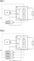
- FIG. 1 shows in a schematic and exemplary manner an uninterruptible power supply system according to the invention, through which in the event of a failure or malfunction of a supplying power network, in particular a three-phase network Supply of a load L (e.g. electrical system) can be maintained.
- the uninterruptible power supply system is connected to the supply network - usually a three-phase network - via a switching power supply SN.
- the switching power supply SN converts a multi-phase alternating voltage (usually a 3-phase alternating voltage) into a direct voltage U (eg 24 V) at the output of the switching power supply SN.
- the uninterruptible power supply system has at least one basic unit GE and at least one accumulator module A1, wherein the accumulator module A1 is mounted spatially separately from the basic unit GE, but is connected to the basic unit GE via lines.
- the basic unit GE includes at least one control unit SE and a loading unit LE.
- the control unit SE can, for example, be designed as a microcontroller and is used to control the charging unit LE.
- Charging and/or discharging processes of the at least one accumulator module A1 are regulated via the charging unit LE - i.e. the charging unit LE ensures that a charging current and/or a charging voltage or a discharging current and/or a discharge voltage remains within predetermined limits.
- the limits for current and voltage such as a level of the charging current (e.g. maximum/minimum charging current), permissible final discharge voltage, etc. can be transmitted from the at least one accumulator module A1 to the basic unit GE, for example, at the time of startup of the power supply system or, for example, during installation or commissioning be permanently set by the operator.
- the basic unit GE has a connection unit ZS.
- the switching unit ZS switches to supplying the load L with the direct voltage U through the at least one accumulator module A1.
- the at least one accumulator module A1 has a monitoring unit UE1 on.
- a small microcontroller for example, can be used as the monitoring unit UE1.
- the monitoring unit UE1 is set up to measure current values of operating parameters such as temperature, terminal voltage, etc. of the associated accumulator A1.
- the monitoring unit UE1 can have corresponding sensors, for example.
- accumulator parameters e.g. end-of-charge voltage, maximum charging current, temperature dependence of the end-of-charge voltage, end-of-discharge voltage, accumulator type, accumulator size, etc.
- accumulator parameters for the associated accumulator A1 are stored in the monitoring unit UE1.
- a digital interface DS is provided, via which data is transmitted between the basic unit GE or the control unit SE of the basic unit GE and the at least one accumulator module A1.
- characteristic battery parameters such as maximum charging current, final discharge voltage, battery type, battery size, etc. can be transmitted from the monitoring unit UE1 to the control unit SE of the basic unit GE.
- the digital interface DS can also be used to transmit current measured values of the operating parameters of the at least one accumulator module A1, which can then be used for further evaluations and/or visual representations in the basic unit GE or in a higher-level control unit.
- an analog interface can be provided for data transmission, in particular for transmitting measured values of the operating parameters (e.g. temperature, voltage, etc.).
- the analog interface is in Figure 1 not shown for reasons of clarity.
- the current measured values of the operating parameters in particular the battery temperature and/or the terminal voltage, can be alternately applied to the analog interface as analog voltage values by the monitoring unit UE1 of the at least one accumulator module A1.
- the voltage values transmitted via the analog interface can be digitized, for example using an analog-digital converter.
- the basic unit GE must be informed via the digital interface which operating parameter is currently being transmitted via the analog interface as an analog voltage value.
- charging-specific states are defined for controlling a charging process as well as for controlling a discharging process. These charging-specific states depend on at least one predetermined accumulator parameter. For example, for the charging process of the accumulator module A1, charging-specific states are defined depending on the end-of-charge voltage - such as "end-of-charge voltage not reached", “end-of-charge voltage reached”, “end-of-charge voltage exceeded”. For the discharging process of the at least one accumulator module A1, for example, the final discharge voltage is used to define the charging-specific states and these are defined, for example, as “final discharge voltage not reached” and "final discharge voltage reached”. These charging-specific states are transmitted via the digital interface DS to the basic unit GE or to the associated control unit SE.
- functional states such as “charging active”, “charging inactive”, “discharging active”, “discharging inactive” can also be defined for the basic unit GE.
- the respective functional states of the basic unit GE are transmitted to the at least one accumulator module A1 via the digital interface DS to start and/or stop the charging or discharging process.
- the charging and/or discharging process of the accumulator module A1 is controlled.
- a charging process is started, for example, with the transfer of the functional state “charging active” from the basic unit GE to the accumulator module A1.
- the control unit SE sets a predetermined constant charging current via the charging unit LE.
- the level of the charging current depends on the battery parameters, which, for example, were transmitted from the battery module A1 or the associated monitoring unit UE1 to the basic unit GE during system startup via the digital interface DS or were determined by the operator of the uninterruptible power supply system during installation or commissioning.
- the operating parameters are then regularly measured by the monitoring unit UE1 of the at least one battery module A1. Based on the current measured values of the operating parameters and based on predetermined accumulator parameters of the at least one accumulator A1, the monitoring unit UE1 then determines the current, charging-specific state of the at least one accumulator module A1. This means that during the charging process, the monitoring unit UE1 regularly compares the current values of the battery temperature and terminal voltage with a temperature-dependent, currently required end-of-charge voltage, which can also be derived from the battery parameters such as a temperature characteristic of the end-of-charge voltage for the type of battery used. Accordingly, from the possible, charging-specific states for the charging process (e.g. "final charging voltage not reached", “final charging voltage reached”, “final charging voltage exceeded”), the currently valid, charging-specific state is transmitted via the digital interface DS to the control unit SE of the basic unit GE.
- a temperature-dependent, currently required end-of-charge voltage which can also be derived from the battery parameters such as a temperature characteristic
- the charging unit LE In the case of a currently transmitted, charging-specific state "final charging voltage not reached", for example, the charging unit LE is instructed by the control unit SE to continue with the constant current charging of the accumulator A1 - that is, to keep the charging current at the specified value.
- the charging unit LE is instructed by the control unit SE to switch from constant current charging to constant voltage charging - that is, the voltage is kept at a constant value.
- the final charging voltage is gradually reduced by means of the control unit SE and via the charging unit LE during constant voltage charging until the monitoring unit UE1 of the at least one accumulator module A1 again reaches the charging-specific state "final charging voltage reached”. is reported or a minimum charging current is not reached.
- the loading process will then stop.
- the basic unit GE then sends the functional state “charging inactive” to the at least one accumulator module A1 via the digital interface DS.
- the functional state "discharging active" can be sent from the basic unit GE to the at least one accumulator module A1 or to the associated monitoring unit UE1 can be sent.
- the operating parameters in particular the voltage, are then regularly measured by the monitoring unit UE1 of the at least one accumulator module A1. Based on the current measured values of the operating parameters and based on predetermined battery parameters of the at least one battery A1, in particular the final discharge voltage of the battery A1, the monitoring unit UE1 then determines the current, charging-specific state of the at least one battery module A1.
- the basic unit GE ends the discharging process in order to prevent the at least one accumulator module A1 from being fully discharged.
- the basic unit GE can, for example, transmit the functional state “discharging inactive” via the digital interface DS to the at least one accumulator module A1 in order to end the discharging.
- FIG 2 again shows schematically and by way of example the uninterruptible power supply system according to the invention with at least the basic unit GE, which has at least the connection unit ZS, the control unit SE and the charging unit LE.
- the uninterruptible power supply system now has several - in Figure 2 three exemplary battery modules A1, A2, A3 connected in parallel.
- Each accumulator module A1, A2, A3 has an associated monitoring unit UE1, UE2, UE3 (e.g. microcontroller) integrated, from which the current values of the operating parameters of the respective accumulator module A1, A2, A3 are measured and the current charging-specific ones based on the stored accumulator parameters States of the associated accumulator module A1, A2, A3 can be determined regularly.
- UE1, UE2 UE3 e.g. microcontroller
- the currently determined states during a charging and/or discharging process - such as "final charge voltage not reached”, “final charge voltage reached”, “final charge voltage exceeded”, “final discharge voltage not reached” and “final discharge voltage reached” - for the respective accumulator module A1, A2, A3 are transmitted from the associated monitoring unit UE1, UE2, UE3 via the digital interface DS to the control unit SE of the basic unit GE.
- the digital interface DS is designed, for example, as a serial data interface, which is routed to all accumulator modules A1, A2, A3 or which is provided by the monitoring units UE1, UE2, UE3 of the accumulator modules A1, A2, A3 is used to transmit the currently determined states to the basic unit GE.
- the charging-specific states currently transmitted by the respective monitoring units UE1, UE2, UE3 are then logically linked in the control unit SE. From this logical link, a corresponding control for the charging unit LE is then determined and the charging or discharging process of the accumulator modules A1, A2, A3 is controlled. This means that if, for example, the charging-specific state "final discharge voltage reached" is reported by one of the accumulator modules A1, A2, A3 during the discharging process, the discharging process for the accumulator modules A1, A2, A3 is ended in order to prevent deep discharging.
- the charging voltage is gradually reduced to the end-of-charge voltage or the charging process is ended when at least one accumulator module A1, A2, A3 has a charging-specific state "end-of-charge voltage exceeded" is transmitted to the basic unit GE via the digital interface DS.
- the number of accumulator modules A1, A2, A3 that can be used by the uninterruptible power supply system depends on a number of communication addresses that can be made available by the digital interface DS used or by the bus for data transmission.
- the accumulator modules A1, A2, A3 can be distinguished via the respective communication address, so that it is possible to understand which accumulator module A1, A2, A3 or which associated monitoring unit UE1, UE2, UE3 has transmitted which charging-specific state or which measurement data for further processing .
Landscapes
- Engineering & Computer Science (AREA)
- Power Engineering (AREA)
- Business, Economics & Management (AREA)
- Emergency Management (AREA)
- Charge And Discharge Circuits For Batteries Or The Like (AREA)
- Stand-By Power Supply Arrangements (AREA)
- Power Sources (AREA)
- Secondary Cells (AREA)
Priority Applications (1)
| Application Number | Priority Date | Filing Date | Title |
|---|---|---|---|
| EP23183530.7A EP4257995A3 (fr) | 2017-06-26 | 2017-06-26 | Procédé de commande d'un système d'alimentation électrique sans coupure et système d'alimentation électrique associé |
Applications Claiming Priority (2)
| Application Number | Priority Date | Filing Date | Title |
|---|---|---|---|
| EP17177934.1A EP3422531A1 (fr) | 2017-06-26 | 2017-06-26 | Procédé de commande d'un système d'alimentation électrique en continu et système d'alimentation électrique associé |
| EP23183530.7A EP4257995A3 (fr) | 2017-06-26 | 2017-06-26 | Procédé de commande d'un système d'alimentation électrique sans coupure et système d'alimentation électrique associé |
Related Parent Applications (1)
| Application Number | Title | Priority Date | Filing Date |
|---|---|---|---|
| EP17177934.1A Division EP3422531A1 (fr) | 2017-06-26 | 2017-06-26 | Procédé de commande d'un système d'alimentation électrique en continu et système d'alimentation électrique associé |
Publications (2)
| Publication Number | Publication Date |
|---|---|
| EP4257995A2 true EP4257995A2 (fr) | 2023-10-11 |
| EP4257995A3 EP4257995A3 (fr) | 2023-11-22 |
Family
ID=59269779
Family Applications (2)
| Application Number | Title | Priority Date | Filing Date |
|---|---|---|---|
| EP23183530.7A Pending EP4257995A3 (fr) | 2017-06-26 | 2017-06-26 | Procédé de commande d'un système d'alimentation électrique sans coupure et système d'alimentation électrique associé |
| EP17177934.1A Ceased EP3422531A1 (fr) | 2017-06-26 | 2017-06-26 | Procédé de commande d'un système d'alimentation électrique en continu et système d'alimentation électrique associé |
Family Applications After (1)
| Application Number | Title | Priority Date | Filing Date |
|---|---|---|---|
| EP17177934.1A Ceased EP3422531A1 (fr) | 2017-06-26 | 2017-06-26 | Procédé de commande d'un système d'alimentation électrique en continu et système d'alimentation électrique associé |
Country Status (3)
| Country | Link |
|---|---|
| US (1) | US11374414B2 (fr) |
| EP (2) | EP4257995A3 (fr) |
| CN (1) | CN109120059B (fr) |
Families Citing this family (3)
| Publication number | Priority date | Publication date | Assignee | Title |
|---|---|---|---|---|
| CN111731150A (zh) * | 2019-10-16 | 2020-10-02 | 北京京东尚科信息技术有限公司 | 一种agv调度方法和装置 |
| WO2021095895A1 (fr) * | 2019-11-11 | 2021-05-20 | 엘지전자 주식회사 | Dispositif électronique et procédé de commande de charge de dispositif électronique |
| DE102021210940A1 (de) | 2021-09-30 | 2023-03-30 | Siemens Aktiengesellschaft | Anordnung umfassend zumindest zwei unterbrechungsfreie Stromversorgungen und Verfahren zu deren Betrieb |
Citations (2)
| Publication number | Priority date | Publication date | Assignee | Title |
|---|---|---|---|---|
| DE19834740A1 (de) | 1998-08-01 | 2000-02-17 | Iq Battery Res & Dev Gmbh | Verfahren zur Batterieüberwachung sowie Batterie mit integrierter Überwachungsvorrichtung |
| DE102010048188A1 (de) | 2010-10-13 | 2012-04-19 | Phoenix Contact Gmbh & Co. Kg | Akkumulator-Kontrollvorrichtung, sowie Verfahren und System zur elektrischen Hilfsversorgung |
Family Cites Families (14)
| Publication number | Priority date | Publication date | Assignee | Title |
|---|---|---|---|---|
| US6184660B1 (en) * | 1998-03-26 | 2001-02-06 | Micro International, Ltd. | High-side current-sensing smart battery charger |
| WO2000002429A1 (fr) * | 1998-07-01 | 2000-01-13 | Mitsubishi Denki Kabushiki Kaisha | Generateur de courant alternatif pour vehicules et refroidisseur integre a ce dernier |
| JP3133031B2 (ja) * | 1998-09-01 | 2001-02-05 | 三菱電機株式会社 | バッテリ充電システム及び情報処理装置 |
| JP2005176461A (ja) * | 2003-12-09 | 2005-06-30 | Matsushita Electric Ind Co Ltd | 直流無停電電源装置 |
| US9263776B2 (en) | 2011-01-06 | 2016-02-16 | Samsung Sdi Co., Ltd. | Battery system and energy storage system including the same |
| EP2688175A4 (fr) * | 2011-03-14 | 2014-09-17 | Sanyo Electric Co | Système de communication et système d'accumulateur |
| JP5701730B2 (ja) * | 2011-09-30 | 2015-04-15 | 株式会社東芝 | 充放電判定装置、充放電判定方法、及び充放電判定プログラム |
| KR101678526B1 (ko) * | 2011-11-17 | 2016-11-23 | 삼성에스디아이 주식회사 | 배터리 시스템, 배터리 시스템의 제어 방법 및 이를 포함하는 전력 저장 시스템 |
| JP6048572B2 (ja) * | 2013-03-15 | 2016-12-21 | 富士電機株式会社 | 無停電電源装置 |
| KR101854218B1 (ko) * | 2013-10-22 | 2018-05-03 | 삼성에스디아이 주식회사 | 배터리 팩, 배터리 팩을 포함하는 에너지 저장 시스템, 배터리 팩의 충전 방법 |
| JP6413311B2 (ja) * | 2014-04-11 | 2018-10-31 | 株式会社村田製作所 | 蓄電装置、制御方法、制御装置、蓄電システム、電動車両および電子機器 |
| JP6242008B2 (ja) | 2014-06-25 | 2017-12-06 | Fdk株式会社 | 無停電電源装置 |
| JP6471463B2 (ja) | 2014-11-06 | 2019-02-20 | 日立化成株式会社 | 蓄電池状態監視システム、蓄電池状態監視方法、および蓄電池状態監視プログラム |
| US10097034B2 (en) * | 2014-12-16 | 2018-10-09 | Cyberpower Systems, Inc. | UPS system with network monitoring and attached battery pack information sensing functions |
-
2017
- 2017-06-26 EP EP23183530.7A patent/EP4257995A3/fr active Pending
- 2017-06-26 EP EP17177934.1A patent/EP3422531A1/fr not_active Ceased
-
2018
- 2018-06-25 US US16/017,364 patent/US11374414B2/en active Active
- 2018-06-26 CN CN201810667600.1A patent/CN109120059B/zh active Active
Patent Citations (2)
| Publication number | Priority date | Publication date | Assignee | Title |
|---|---|---|---|---|
| DE19834740A1 (de) | 1998-08-01 | 2000-02-17 | Iq Battery Res & Dev Gmbh | Verfahren zur Batterieüberwachung sowie Batterie mit integrierter Überwachungsvorrichtung |
| DE102010048188A1 (de) | 2010-10-13 | 2012-04-19 | Phoenix Contact Gmbh & Co. Kg | Akkumulator-Kontrollvorrichtung, sowie Verfahren und System zur elektrischen Hilfsversorgung |
Also Published As
| Publication number | Publication date |
|---|---|
| US20180375346A1 (en) | 2018-12-27 |
| EP3422531A1 (fr) | 2019-01-02 |
| US11374414B2 (en) | 2022-06-28 |
| CN109120059A (zh) | 2019-01-01 |
| CN109120059B (zh) | 2022-10-21 |
| EP4257995A3 (fr) | 2023-11-22 |
Similar Documents
| Publication | Publication Date | Title |
|---|---|---|
| EP2047579B1 (fr) | Système d'alimentation électrique des charges électriques d'un véhicule automobile en utilisant un supercondensateur | |
| EP3701584B1 (fr) | Procédé de charge ou de décharge d'un accumulateur d'énergie | |
| EP3072205B1 (fr) | Système de gestion de batterie pour commander un ensemble de stockage d'énergie et procédé de charge et de décharge d'un ensemble de stockage d'énergie | |
| EP2435279B1 (fr) | Réseau de bord pour un véhicule ainsi que dispositif de commande pour un réseau de bord | |
| EP3207585B1 (fr) | Procédé de fonctionnement d'un réseau électrique, notamment d'un réseau électrique d'engin nautique | |
| EP3017521B1 (fr) | Dispositif et procédé permettant d'équilibrer la charge d'un ensemble d'accumulation d'énergie | |
| DE102013225221A1 (de) | Batteriesystem | |
| DE102015203367A1 (de) | Inselbetriebssystem | |
| DE102009001670A1 (de) | Ladeverfahren und Ladesystem | |
| EP2949021B1 (fr) | Dispositif de controle pour un système de stockage d'énergie électrique | |
| DE202016105015U1 (de) | Speichersystem zur Speicherung elektrischer Energie | |
| EP4257995A2 (fr) | Procédé de commande d'un système d'alimentation électrique sans coupure et système d'alimentation électrique associé | |
| DE102013222715A1 (de) | Elektroenergie-Steuersystem | |
| DE102013220609A1 (de) | Energieversorgungssystem für ein Bordnetz eines Fahrzeugs | |
| DE102012015522A1 (de) | Batterielager- und -logistiksystem | |
| DE10153083B4 (de) | Ladeeinrichtung | |
| EP3618219B1 (fr) | Procédé de restauration d'un module de batterie sur-déchargé et système d'alimentation ininterruptible correspondant | |
| WO2012123138A1 (fr) | Dispositif accumulateur servant à accumuler de l'énergie électrique et procédé permettant de faire fonctionner un dispositif accumulateur | |
| DE102010053824A1 (de) | System und Verfahren zum Regeln des Ladezustands einer Mehrzahl an Batterien während deren Lagerung | |
| EP3079222A1 (fr) | Dispositif d'alimentation en energie pour un systeme de gestion de batterie | |
| WO2019007879A1 (fr) | Appareil de commande principale pour un système de batterie | |
| DE102014222039A1 (de) | Vorrichtung einer Fahrzeugenergiequelle | |
| DE102019217277A1 (de) | Energiespeichereinheit, Energiespeichersystem, Verfahren zum Betreiben einer Energiespeichereinheit und Verfahren zum Betreiben eines Energiespeichersystems | |
| DE102014201196A1 (de) | Verfahren zum Betreiben eines Batteriemanagementsystems und Batteriemanagementsystem | |
| DE102010012089A1 (de) | Verfahren und Vorrichtung zum Laden eines Akkumulators in einem Hybridsystem aus Brennstoffzelle und Akkumulatoren |
Legal Events
| Date | Code | Title | Description |
|---|---|---|---|
| PUAI | Public reference made under article 153(3) epc to a published international application that has entered the european phase |
Free format text: ORIGINAL CODE: 0009012 |
|
| STAA | Information on the status of an ep patent application or granted ep patent |
Free format text: STATUS: THE APPLICATION HAS BEEN PUBLISHED |
|
| AC | Divisional application: reference to earlier application |
Ref document number: 3422531 Country of ref document: EP Kind code of ref document: P |
|
| AK | Designated contracting states |
Kind code of ref document: A2 Designated state(s): AL AT BE BG CH CY CZ DE DK EE ES FI FR GB GR HR HU IE IS IT LI LT LU LV MC MK MT NL NO PL PT RO RS SE SI SK SM TR |
|
| REG | Reference to a national code |
Ref country code: DE Ref legal event code: R079 Free format text: PREVIOUS MAIN CLASS: G01R0031360000 Ipc: H02J0009060000 |
|
| PUAL | Search report despatched |
Free format text: ORIGINAL CODE: 0009013 |
|
| AK | Designated contracting states |
Kind code of ref document: A3 Designated state(s): AL AT BE BG CH CY CZ DE DK EE ES FI FR GB GR HR HU IE IS IT LI LT LU LV MC MK MT NL NO PL PT RO RS SE SI SK SM TR |
|
| RIC1 | Information provided on ipc code assigned before grant |
Ipc: G01R 31/36 20200101ALI20231017BHEP Ipc: H02J 7/00 20060101ALI20231017BHEP Ipc: H02J 9/06 20060101AFI20231017BHEP |