EP4257995A2 - Method for controlling an uninterruptible power supply system and corresponding power supply system - Google Patents
Method for controlling an uninterruptible power supply system and corresponding power supply system Download PDFInfo
- Publication number
- EP4257995A2 EP4257995A2 EP23183530.7A EP23183530A EP4257995A2 EP 4257995 A2 EP4257995 A2 EP 4257995A2 EP 23183530 A EP23183530 A EP 23183530A EP 4257995 A2 EP4257995 A2 EP 4257995A2
- Authority
- EP
- European Patent Office
- Prior art keywords
- charging
- unit
- accumulator module
- basic unit
- accumulator
- Prior art date
- Legal status (The legal status is an assumption and is not a legal conclusion. Google has not performed a legal analysis and makes no representation as to the accuracy of the status listed.)
- Pending
Links
- 238000000034 method Methods 0.000 title claims abstract description 89
- 238000007600 charging Methods 0.000 claims abstract description 166
- 238000012544 monitoring process Methods 0.000 claims abstract description 57
- 238000007599 discharging Methods 0.000 claims abstract description 49
- 239000008186 active pharmaceutical agent Substances 0.000 claims description 19
- 238000011156 evaluation Methods 0.000 claims description 5
- 230000000007 visual effect Effects 0.000 claims description 4
- 230000005540 biological transmission Effects 0.000 abstract description 9
- 230000001276 controlling effect Effects 0.000 description 10
- 238000004891 communication Methods 0.000 description 5
- 238000010280 constant potential charging Methods 0.000 description 4
- 230000001419 dependent effect Effects 0.000 description 3
- HBBGRARXTFLTSG-UHFFFAOYSA-N Lithium ion Chemical compound [Li+] HBBGRARXTFLTSG-UHFFFAOYSA-N 0.000 description 2
- 230000033228 biological regulation Effects 0.000 description 2
- 238000010277 constant-current charging Methods 0.000 description 2
- 238000010281 constant-current constant-voltage charging Methods 0.000 description 2
- 238000009434 installation Methods 0.000 description 2
- 229910001416 lithium ion Inorganic materials 0.000 description 2
- 230000007257 malfunction Effects 0.000 description 2
- 230000001105 regulatory effect Effects 0.000 description 2
- 238000012546 transfer Methods 0.000 description 2
- 230000032683 aging Effects 0.000 description 1
- 230000009286 beneficial effect Effects 0.000 description 1
- 230000003139 buffering effect Effects 0.000 description 1
- 230000007423 decrease Effects 0.000 description 1
- 238000004146 energy storage Methods 0.000 description 1
- 239000000463 material Substances 0.000 description 1
- 238000005259 measurement Methods 0.000 description 1
- 238000012545 processing Methods 0.000 description 1
- 230000035882 stress Effects 0.000 description 1
- 239000000126 substance Substances 0.000 description 1
Images
Classifications
-
- H—ELECTRICITY
- H02—GENERATION; CONVERSION OR DISTRIBUTION OF ELECTRIC POWER
- H02J—CIRCUIT ARRANGEMENTS OR SYSTEMS FOR SUPPLYING OR DISTRIBUTING ELECTRIC POWER; SYSTEMS FOR STORING ELECTRIC ENERGY
- H02J9/00—Circuit arrangements for emergency or stand-by power supply, e.g. for emergency lighting
- H02J9/04—Circuit arrangements for emergency or stand-by power supply, e.g. for emergency lighting in which the distribution system is disconnected from the normal source and connected to a standby source
- H02J9/06—Circuit arrangements for emergency or stand-by power supply, e.g. for emergency lighting in which the distribution system is disconnected from the normal source and connected to a standby source with automatic change-over, e.g. UPS systems
- H02J9/061—Circuit arrangements for emergency or stand-by power supply, e.g. for emergency lighting in which the distribution system is disconnected from the normal source and connected to a standby source with automatic change-over, e.g. UPS systems for DC powered loads
-
- G—PHYSICS
- G01—MEASURING; TESTING
- G01R—MEASURING ELECTRIC VARIABLES; MEASURING MAGNETIC VARIABLES
- G01R31/00—Arrangements for testing electric properties; Arrangements for locating electric faults; Arrangements for electrical testing characterised by what is being tested not provided for elsewhere
- G01R31/36—Arrangements for testing, measuring or monitoring the electrical condition of accumulators or electric batteries, e.g. capacity or state of charge [SoC]
- G01R31/382—Arrangements for monitoring battery or accumulator variables, e.g. SoC
- G01R31/3835—Arrangements for monitoring battery or accumulator variables, e.g. SoC involving only voltage measurements
-
- H—ELECTRICITY
- H01—ELECTRIC ELEMENTS
- H01M—PROCESSES OR MEANS, e.g. BATTERIES, FOR THE DIRECT CONVERSION OF CHEMICAL ENERGY INTO ELECTRICAL ENERGY
- H01M10/00—Secondary cells; Manufacture thereof
- H01M10/42—Methods or arrangements for servicing or maintenance of secondary cells or secondary half-cells
- H01M10/425—Structural combination with electronic components, e.g. electronic circuits integrated to the outside of the casing
- H01M10/4257—Smart batteries, e.g. electronic circuits inside the housing of the cells or batteries
Definitions
- the present invention generally relates to uninterruptible power supply systems or so-called uninterruptable power supply or UPS systems.
- the present invention relates to a method for controlling an uninterruptible power supply system and an associated uninterruptible power supply system for carrying out the method according to the invention.
- the uninterruptible power supply system includes at least one basic unit and at least one accumulator module with a monitoring unit.
- the basic unit has at least one charging unit and a control unit for controlling the charging unit and can be mounted spatially separately from the at least one accumulator module.
- UPS uninterruptible power supply systems
- UPS uninterruptable power supply
- An uninterruptible power supply system typically consists of a basic unit and one or more accumulator modules, which usually includes an accumulator for energy storage.
- An accumulator is a rechargeable storage device for electrical energy, typically based on an electrochemical system, through which electrical energy is converted into chemical (storage) energy when charging and converted back into electrical energy when discharging.
- Types of accumulators are usually named after the materials used.
- Well-known types of accumulators are, for example, lithium-ion accumulators, lead accumulators, etc.
- the term rechargeable battery or battery can also be used synonymously for the term accumulator or battery for short.
- the accumulator module can also include a monitoring unit - such as from the document DE 198 34 740 A1 known.
- This monitoring unit can be used to monitor the battery and can determine operating parameters of the battery (e.g. battery temperature, battery voltage, etc.) as well as characteristic battery parameters (e.g. final charge voltage, maximum charging current, temperature dependence of the final charge voltage, final discharge voltage, accumulator type, accumulator size, etc.). and save.
- the basic unit of the uninterruptible power supply which is connected on the input side to the power supply and on the output side to a load to be supplied, comprises at least one charging unit or a charge controller and a control unit.
- the charging unit or the charge controller is used to charge the accumulator module or modules and to implement a charging or discharging process.
- the control unit is used to control the charging unit or the charge controller.
- the basic unit has a connection unit through which the at least one accumulator module can be connected to the load in the event of a fault or failure of the energy supply network.
- the basic unit and the battery module or battery modules can be installed spatially separated from one another.
- the basic unit with charging unit, control unit and connection unit is located, for example, in a housing that is mounted on a top-hat rail in a control cabinet, for example.
- the associated accumulator module or modules can, for example, be attached to the bottom of the control cabinet or another location because of the lower temperature level.
- the uninterruptible power supply Without disruptions to the energy supply, electrical energy is passed on from the uninterruptible power supply to both the connected load and to the at least one associated battery module - i.e. the battery is charged.
- the at least one accumulator module of the uninterruptible power supply is connected to the load and begins to discharge towards the load in order to maintain the electrical power supply.
- the energy supply network returns to its normal state, the load and the at least one accumulator module are in turn supplied with electrical energy. This means that with an uninterruptible power supply, the at least one battery is charged during normal operation of the energy supply network and discharged in the event of a fault.
- IU charging process or constant current constant voltage process (CCCV process) is often used when charging batteries that are commonly used today (e.g. lead accumulator, lithium-ion battery, etc.), which is the so-called constant current the constant voltage charging process.
- CCCV process constant current constant voltage process
- the battery In the first phase of the charging process, the battery is charged with a constant current. The voltage at the battery terminals increases as the charge level increases.
- end of charge voltage is reached on the battery, the basic unit switches from current to voltage regulation.
- the second charging phase charging continues at a constant voltage, with the voltage at the battery terminals being kept at a constant value.
- the charging current automatically decreases continuously until a predetermined minimum value is reached, which can be used as a criterion for terminating the charging process, for example by the basic unit.
- the discharging process should be terminated by the basic unit when a so-called final discharge voltage is reached or falls below - another characteristic value of the respective battery.
- the final discharge voltage is one fixed voltage up to which the battery can be discharged and depends on the respective battery type.
- the basic unit in which the control unit and charging unit are mounted for controlling and regulating the charging and discharging process, is often spatially separated from the accumulator or accumulators of the uninterruptible power supply system.
- appropriate data e.g. battery parameters, current values of operating parameters such as temperature, voltage, etc.
- corresponding data e.g. current values of operating parameters such as battery voltage, etc.
- an accumulator control device and an associated method for electrical auxiliary supplies are known, in which current measured values of operating parameters - in particular battery temperature and battery voltage - are transmitted from the accumulator to an auxiliary supply device for controlling the charging and / or discharging process.
- the accumulator is preceded by an accumulator control device, which transmits the parameter values required for an optimal charging or discharging process (e.g. battery temperature, battery voltage, basic value of the final charge or discharge voltage, temperature characteristics of the battery, etc.) from the accumulator via a bus to the Auxiliary supply device transmitted.
- the accumulator control device has a microcontroller, which measures, evaluates and transmits controls these parameter values. If several batteries are connected to the basic unit, they are connected together via a terminal block, with each battery being assigned its own unique communication address for transferring the data from the respective battery.
- a relatively large amount of data (such as current measured values, required parameters for an optimal charging or discharging process, etc.) is stored between the respective accumulator control device and the auxiliary supply device for controlling the respective charging or discharging process. Discharging process are transferred. The amount of data must then be evaluated by the auxiliary supply device - especially when using several accumulators - with relatively great effort to control the charging or discharging process.
- errors in the transmission of the amount of data via the bus that connects the accumulator control device with the auxiliary supply device errors can also occur in the evaluation of the relatively large amount of data in the auxiliary supply device and thus incorrect control when charging and / or discharging the respective battery .
- the invention is therefore based on the object of specifying a method for controlling an uninterruptible power supply system and an associated uninterruptible power supply system, through which control of a charging and/or discharging process of accumulators used in the uninterruptible power supply system - in particular when spatially separated from a basic unit can be easily improved and the probability of errors reduced.
- the object is achieved by a method for controlling an uninterruptible power supply system of the type mentioned at the beginning, wherein during the method during a charging process and / or during a discharging process of at least one accumulator module, a current, charging-specific state of the at least one accumulator module is regularly monitored by a monitoring unit of the at least one accumulator module at least one accumulator module is determined.
- the current, charging-specific state of the at least one accumulator module is transmitted to the basic unit of the uninterruptible power supply system. There, the currently transmitted, charging-specific state is evaluated by the control unit of the basic unit and the charging unit of the basic unit is activated accordingly.
- the main aspect of the method according to the invention is that charging and discharging processes of one or more battery modules in an uninterruptible power supply system can be controlled in a simple manner and incorrect control, which can possibly lead to damage to the battery module(s), can be reduced.
- the method according to the invention only the current, charging-specific states of the at least one accumulator module - for example in the form of digital status signals - are transmitted between the monitoring unit of the at least one accumulator module and the basic unit or associated control unit.
- a transmission of current measured values of accumulator parameters such as temperature, voltage, etc. can be omitted, which means that the susceptibility to errors can be significantly reduced.
- the present invention has a significantly smaller amount of data to be transmitted by reducing the communication between the at least one accumulator module or associated monitoring unit and the basic unit of the power supply system, in particular the control unit, for example, to digital status signals, which significantly increases transmission reliability.
- the monitoring unit determines a current, charging-specific state for each accumulator module and transmits it to the control unit in the basic unit.
- the current, charging-specific states of the accumulator modules can, for example, be logically linked and, in the simplest case, the charging unit can be controlled by the control unit in such a way that, for example, when the final charging voltage of a first accumulator is reached or when the final discharge voltage of a first accumulator is reached, the charging process or the Unloading (or buffering) is completed. This very easily prevents stress and/or damage to the batteries used, for example due to overcharging or deep discharging.
- the respective current, charging-specific state of the at least one accumulator module will be determined by the monitoring unit based on current measured values of operating parameters of the at least one accumulator module and based on predetermined accumulator parameters for the at least one accumulator module.
- the monitoring unit measures, for example, a current temperature and/or a current terminal voltage of the at least one accumulator as operating parameters.
- characteristic battery parameters specified by the monitoring unit are used to determine the current, charging-specific state, such as a temperature characteristic of the end-of-charge voltage of the respective battery, type and/or size of the battery, end-of-charge voltage, end-of-discharge voltage, maximum level of the charging current, etc. are used.
- These accumulator parameters For example, they can be made available to the monitoring unit at a time when the system is starting up or can be permanently stored in the monitoring unit by the operator or manufacturer of the uninterruptible power supply system.
- the charging-specific states of the at least one accumulator module are defined as a function of at least one predetermined, characteristic accumulator parameter for the charging process or for the discharging process.
- charging-specific states can be defined for the charging process depending on the final charging voltage of the respective battery. Possible charging-specific states can be defined, for example, “final charging voltage not reached”, “final charging voltage reached” and “final charging voltage exceeded”.
- charging-specific states can be defined for the discharging process of the at least one battery module depending on the final discharge voltage of the respective battery - such as "final discharge voltage not reached” and "final discharge voltage reached”.
- functional states are also defined for the basic unit. Through these functional states, the respective charging process and/or the respective discharging process can be started and/or stopped in a simple manner. For this purpose, for example, functional states such as “charging active”, “charging inactive”, “discharging active”, “discharging inactive” can be defined. These functional states can be transmitted to the at least one accumulator module or to the associated monitoring unit.
- a further, advantageous embodiment variant of the method according to the invention provides that the current measured values of the operating parameters such as temperature, terminal voltage, etc. of the at least one accumulator module are sent to the basic unit of the uninterruptible power supply system and/or to a control unit which is connected to the uninterruptible The power supply system is higher-level.
- the transmitted measured values of the operating parameters can then be used for further evaluations and/or visual representations, on the basis of which a more in-depth assessment of, for example, operational readiness, aging process, etc. of the at least one accumulator module can be carried out.
- the current, charging-specific states of the at least one accumulator module and the functional states of the basic unit are transmitted via a digital interface between the basic unit and the at least one accumulator module or the associated monitoring unit.
- the amount of data to be transmitted or the communication between the basic unit and the at least one accumulator module is thus reduced to a transmission of purely digital status signals.
- This increases transmission security.
- the amount of data to be transmitted and data handling will be significantly simplified through the use of digital status signals and a digital interface.
- the current measured values of the operating parameters can also be easily transmitted from the monitoring unit to the basic unit via the digital interface.
- the operating parameters, in particular temperature and/or terminal voltage, measured by the monitoring unit of the at least one accumulator module are digitized and transmitted as digital values. These can be evaluated or displayed visually relatively easily in the basic unit or a higher-level control unit.
- an analog interface can be implemented between the basic unit and the at least one accumulator module or the associated monitoring unit. You can use this analog interface the current measured values of the operating parameters are transmitted - alternatively or additionally - from the monitoring unit to the basic unit, in particular the control unit. For this purpose, the current measured values of the operating parameters, in particular the battery temperature and/or the terminal voltage, are alternately applied to the analog interface as analog voltage values by the monitoring unit of the at least one accumulator module.
- the voltage values transmitted via the analog interface can be digitized, for example using an analog-digital converter. Furthermore, the basic unit is informed via the digital interface which operating parameter is currently being transmitted via the analog interface as an analog voltage value for correct interpretation.
- This uninterruptible power supply system consists of at least a basic unit and at least one accumulator module.
- the basic unit includes at least one loading unit and a control unit, through which the loading unit is controlled primarily to regulate loading and unloading processes.
- the at least one accumulator module has a monitoring unit and can be mounted spatially separately from the basic unit. Furthermore, the monitoring unit of the at least one accumulator module is set up to regularly determine a current, charging-specific state of the at least one accumulator module and to transmit it to the basic unit.
- the control unit of the basic unit is set up to evaluate the currently transmitted, charging-specific state of the at least one accumulator module and to control the charging unit accordingly.
- the main aspect of the uninterruptible power supply system according to the invention is also to reduce the amount of data to be transmitted between the basic unit and the accumulator module or the associated monitoring unit and to increase transmission security.
- the uninterruptible power supply system according to the invention for a charging and/or discharging process of the at least one accumulator module, only the current states for the control and regulation are transmitted to the basic unit. A transfer of current measured values of the operating parameters (e.g. battery temperature, terminal voltage, etc.) is therefore not necessary.
- the monitoring unit of the at least one battery module is ideally set up to measure current values of operating parameters, in particular the battery temperature and/or the terminal voltage.
- the monitoring unit can have corresponding sensors, for example.
- a current, charging-specific state such as e.g. "final charge voltage not reached”, “final charge voltage reached”, “final charge voltage exceeded”, “final discharge voltage not reached”, “final discharge voltage reached” for the charging process or discharging process can be determined and the basic unit is transferred.
- a digital interface is also advantageously provided for transmitting the current, charging-specific states to the basic unit.
- the digital interface can also be used for transmitting functional states (e.g. "charging active”, “charging inactive”, “discharging active”, “discharging inactive”), which can be defined for the basic unit.
- functional states e.g. "charging active”, “charging inactive”, “discharging active”, “discharging inactive”
- the digital interface can be used for transmitting current measured values of the operating parameters of the at least one accumulator module.
- the measured values can therefore be used for the basic unit of the uninterruptible power supply system and/or for a higher-level control unit for more in-depth evaluations and/or visual representation, in particular regarding the battery functionality.
- an analog interface can also be provided in the uninterruptible power supply system according to the invention.
- the current measured values of the operating parameters of the at least one accumulator module can be transmitted to the basic unit via the analog interface, for example in the form of voltage values.
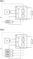
- FIG. 1 shows in a schematic and exemplary manner an uninterruptible power supply system according to the invention, through which in the event of a failure or malfunction of a supplying power network, in particular a three-phase network Supply of a load L (e.g. electrical system) can be maintained.
- the uninterruptible power supply system is connected to the supply network - usually a three-phase network - via a switching power supply SN.
- the switching power supply SN converts a multi-phase alternating voltage (usually a 3-phase alternating voltage) into a direct voltage U (eg 24 V) at the output of the switching power supply SN.
- the uninterruptible power supply system has at least one basic unit GE and at least one accumulator module A1, wherein the accumulator module A1 is mounted spatially separately from the basic unit GE, but is connected to the basic unit GE via lines.
- the basic unit GE includes at least one control unit SE and a loading unit LE.
- the control unit SE can, for example, be designed as a microcontroller and is used to control the charging unit LE.
- Charging and/or discharging processes of the at least one accumulator module A1 are regulated via the charging unit LE - i.e. the charging unit LE ensures that a charging current and/or a charging voltage or a discharging current and/or a discharge voltage remains within predetermined limits.
- the limits for current and voltage such as a level of the charging current (e.g. maximum/minimum charging current), permissible final discharge voltage, etc. can be transmitted from the at least one accumulator module A1 to the basic unit GE, for example, at the time of startup of the power supply system or, for example, during installation or commissioning be permanently set by the operator.
- the basic unit GE has a connection unit ZS.
- the switching unit ZS switches to supplying the load L with the direct voltage U through the at least one accumulator module A1.
- the at least one accumulator module A1 has a monitoring unit UE1 on.
- a small microcontroller for example, can be used as the monitoring unit UE1.
- the monitoring unit UE1 is set up to measure current values of operating parameters such as temperature, terminal voltage, etc. of the associated accumulator A1.
- the monitoring unit UE1 can have corresponding sensors, for example.
- accumulator parameters e.g. end-of-charge voltage, maximum charging current, temperature dependence of the end-of-charge voltage, end-of-discharge voltage, accumulator type, accumulator size, etc.
- accumulator parameters for the associated accumulator A1 are stored in the monitoring unit UE1.
- a digital interface DS is provided, via which data is transmitted between the basic unit GE or the control unit SE of the basic unit GE and the at least one accumulator module A1.
- characteristic battery parameters such as maximum charging current, final discharge voltage, battery type, battery size, etc. can be transmitted from the monitoring unit UE1 to the control unit SE of the basic unit GE.
- the digital interface DS can also be used to transmit current measured values of the operating parameters of the at least one accumulator module A1, which can then be used for further evaluations and/or visual representations in the basic unit GE or in a higher-level control unit.
- an analog interface can be provided for data transmission, in particular for transmitting measured values of the operating parameters (e.g. temperature, voltage, etc.).
- the analog interface is in Figure 1 not shown for reasons of clarity.
- the current measured values of the operating parameters in particular the battery temperature and/or the terminal voltage, can be alternately applied to the analog interface as analog voltage values by the monitoring unit UE1 of the at least one accumulator module A1.
- the voltage values transmitted via the analog interface can be digitized, for example using an analog-digital converter.
- the basic unit GE must be informed via the digital interface which operating parameter is currently being transmitted via the analog interface as an analog voltage value.
- charging-specific states are defined for controlling a charging process as well as for controlling a discharging process. These charging-specific states depend on at least one predetermined accumulator parameter. For example, for the charging process of the accumulator module A1, charging-specific states are defined depending on the end-of-charge voltage - such as "end-of-charge voltage not reached", “end-of-charge voltage reached”, “end-of-charge voltage exceeded”. For the discharging process of the at least one accumulator module A1, for example, the final discharge voltage is used to define the charging-specific states and these are defined, for example, as “final discharge voltage not reached” and "final discharge voltage reached”. These charging-specific states are transmitted via the digital interface DS to the basic unit GE or to the associated control unit SE.
- functional states such as “charging active”, “charging inactive”, “discharging active”, “discharging inactive” can also be defined for the basic unit GE.
- the respective functional states of the basic unit GE are transmitted to the at least one accumulator module A1 via the digital interface DS to start and/or stop the charging or discharging process.
- the charging and/or discharging process of the accumulator module A1 is controlled.
- a charging process is started, for example, with the transfer of the functional state “charging active” from the basic unit GE to the accumulator module A1.
- the control unit SE sets a predetermined constant charging current via the charging unit LE.
- the level of the charging current depends on the battery parameters, which, for example, were transmitted from the battery module A1 or the associated monitoring unit UE1 to the basic unit GE during system startup via the digital interface DS or were determined by the operator of the uninterruptible power supply system during installation or commissioning.
- the operating parameters are then regularly measured by the monitoring unit UE1 of the at least one battery module A1. Based on the current measured values of the operating parameters and based on predetermined accumulator parameters of the at least one accumulator A1, the monitoring unit UE1 then determines the current, charging-specific state of the at least one accumulator module A1. This means that during the charging process, the monitoring unit UE1 regularly compares the current values of the battery temperature and terminal voltage with a temperature-dependent, currently required end-of-charge voltage, which can also be derived from the battery parameters such as a temperature characteristic of the end-of-charge voltage for the type of battery used. Accordingly, from the possible, charging-specific states for the charging process (e.g. "final charging voltage not reached", “final charging voltage reached”, “final charging voltage exceeded”), the currently valid, charging-specific state is transmitted via the digital interface DS to the control unit SE of the basic unit GE.
- a temperature-dependent, currently required end-of-charge voltage which can also be derived from the battery parameters such as a temperature characteristic
- the charging unit LE In the case of a currently transmitted, charging-specific state "final charging voltage not reached", for example, the charging unit LE is instructed by the control unit SE to continue with the constant current charging of the accumulator A1 - that is, to keep the charging current at the specified value.
- the charging unit LE is instructed by the control unit SE to switch from constant current charging to constant voltage charging - that is, the voltage is kept at a constant value.
- the final charging voltage is gradually reduced by means of the control unit SE and via the charging unit LE during constant voltage charging until the monitoring unit UE1 of the at least one accumulator module A1 again reaches the charging-specific state "final charging voltage reached”. is reported or a minimum charging current is not reached.
- the loading process will then stop.
- the basic unit GE then sends the functional state “charging inactive” to the at least one accumulator module A1 via the digital interface DS.
- the functional state "discharging active" can be sent from the basic unit GE to the at least one accumulator module A1 or to the associated monitoring unit UE1 can be sent.
- the operating parameters in particular the voltage, are then regularly measured by the monitoring unit UE1 of the at least one accumulator module A1. Based on the current measured values of the operating parameters and based on predetermined battery parameters of the at least one battery A1, in particular the final discharge voltage of the battery A1, the monitoring unit UE1 then determines the current, charging-specific state of the at least one battery module A1.
- the basic unit GE ends the discharging process in order to prevent the at least one accumulator module A1 from being fully discharged.
- the basic unit GE can, for example, transmit the functional state “discharging inactive” via the digital interface DS to the at least one accumulator module A1 in order to end the discharging.
- FIG 2 again shows schematically and by way of example the uninterruptible power supply system according to the invention with at least the basic unit GE, which has at least the connection unit ZS, the control unit SE and the charging unit LE.
- the uninterruptible power supply system now has several - in Figure 2 three exemplary battery modules A1, A2, A3 connected in parallel.
- Each accumulator module A1, A2, A3 has an associated monitoring unit UE1, UE2, UE3 (e.g. microcontroller) integrated, from which the current values of the operating parameters of the respective accumulator module A1, A2, A3 are measured and the current charging-specific ones based on the stored accumulator parameters States of the associated accumulator module A1, A2, A3 can be determined regularly.
- UE1, UE2 UE3 e.g. microcontroller
- the currently determined states during a charging and/or discharging process - such as "final charge voltage not reached”, “final charge voltage reached”, “final charge voltage exceeded”, “final discharge voltage not reached” and “final discharge voltage reached” - for the respective accumulator module A1, A2, A3 are transmitted from the associated monitoring unit UE1, UE2, UE3 via the digital interface DS to the control unit SE of the basic unit GE.
- the digital interface DS is designed, for example, as a serial data interface, which is routed to all accumulator modules A1, A2, A3 or which is provided by the monitoring units UE1, UE2, UE3 of the accumulator modules A1, A2, A3 is used to transmit the currently determined states to the basic unit GE.
- the charging-specific states currently transmitted by the respective monitoring units UE1, UE2, UE3 are then logically linked in the control unit SE. From this logical link, a corresponding control for the charging unit LE is then determined and the charging or discharging process of the accumulator modules A1, A2, A3 is controlled. This means that if, for example, the charging-specific state "final discharge voltage reached" is reported by one of the accumulator modules A1, A2, A3 during the discharging process, the discharging process for the accumulator modules A1, A2, A3 is ended in order to prevent deep discharging.
- the charging voltage is gradually reduced to the end-of-charge voltage or the charging process is ended when at least one accumulator module A1, A2, A3 has a charging-specific state "end-of-charge voltage exceeded" is transmitted to the basic unit GE via the digital interface DS.
- the number of accumulator modules A1, A2, A3 that can be used by the uninterruptible power supply system depends on a number of communication addresses that can be made available by the digital interface DS used or by the bus for data transmission.
- the accumulator modules A1, A2, A3 can be distinguished via the respective communication address, so that it is possible to understand which accumulator module A1, A2, A3 or which associated monitoring unit UE1, UE2, UE3 has transmitted which charging-specific state or which measurement data for further processing .
Abstract
Die Erfindung betrifft ein Verfahren zur Steuerung eines unterbrechungsfreien Stromversorgungssystems sowie ein zugehöriges, unterbrechungsfreies Stromversorgungssystem zur Durchführung des erfindungsgemäßen Verfahrens. Dabei umfasst das unterbrechungsfreie Stromversorgungssystem mindestens eine Grundeinheit (GE) sowie zumindest ein Akkumulatormodul (A1, A2, A3) mit einer Überwachungseinheit (UE1, UE2, UE3). Die Grundeinheit (GE) weist dabei zumindest eine Ladeeinheit (LE) sowie eine Steuereinheit (SE) zum Ansteuern der Ladeeinheit (LE) auf und kann vom zumindest einen Akkumulatormodul (A1, A2, A3) räumlich getrennt angebracht werden. Von der Überwachungseinheit (UE1, UE2, UE3) des zumindest einen Akkumulatormoduls (A1, A2, A3) wird regelmäßig während eine Lade- und/oder Entladevorgangs ein jeweils aktueller, ladespezifischer Zustand des zumindest einen Akkumulatormoduls (A1, A2, A3) ermittelt und an die Grundeinheit (GE) übertragen. In der Grundeinheit (GE) wird der aktuell übertragene, ladespezifische Zustand des zumindest einen Akkumulatormoduls (A1, A2, A3) von der Steuereinheit (SE) ausgewertet und die Ladeeinheit (SE) der Grundeinheit (GE) entsprechend angesteuert. Dadurch wird die zwischen der Grundeinheit (GE) und dem zumindest einen Akkumulatormodul (A1, A2, A3) der unterbrechungsfreien Stromversorgungseinheit übertragene Datenmenge erheblich reduziert und die Übertragungssicherheit gesteigert.The invention relates to a method for controlling an uninterruptible power supply system and an associated uninterruptible power supply system for carrying out the method according to the invention. The uninterruptible power supply system includes at least one basic unit (GE) and at least one accumulator module (A1, A2, A3) with a monitoring unit (UE1, UE2, UE3). The basic unit (GE) has at least one charging unit (LE) and a control unit (SE) for controlling the charging unit (LE) and can be mounted spatially separately from the at least one accumulator module (A1, A2, A3). The monitoring unit (UE1, UE2, UE3) of the at least one accumulator module (A1, A2, A3) regularly determines a current, charging-specific state of the at least one accumulator module (A1, A2, A3) during a charging and/or discharging process and transferred to the basic unit (GE). In the basic unit (GE), the currently transmitted, charging-specific state of the at least one accumulator module (A1, A2, A3) is evaluated by the control unit (SE) and the charging unit (SE) of the basic unit (GE) is controlled accordingly. As a result, the amount of data transmitted between the basic unit (GE) and the at least one accumulator module (A1, A2, A3) of the uninterruptible power supply unit is significantly reduced and the transmission security is increased.
Description
Die vorliegende Erfindung betrifft allgemein unterbrechungsfreie Stromversorgungssysteme oder so genannte Uninterruptable Power Supply- bzw. UPS-Systeme. Im Speziellen bezieht sich die vorliegende Erfindung auf ein Verfahren zur Steuerung eines unterbrechungsfreien Stromversorgungssystems sowie auf ein zugehöriges, unterbrechungsfreies Stromversorgungssystem zur Durchführung des erfindungsgemäßen Verfahrens. Dabei umfasst das unterbrechungsfreie Stromversorgungssystem mindestens eine Grundeinheit sowie zumindest ein Akkumulatormodul mit einer Überwachungseinheit. Die Grundeinheit weist dabei zumindest eine Ladeeinheit sowie eine Steuereinheit zum Ansteuern der Ladeeinheit auf und kann vom zumindest einen Ackumulatormodul räumlich getrennt angebracht werden.The present invention generally relates to uninterruptible power supply systems or so-called uninterruptable power supply or UPS systems. In particular, the present invention relates to a method for controlling an uninterruptible power supply system and an associated uninterruptible power supply system for carrying out the method according to the invention. The uninterruptible power supply system includes at least one basic unit and at least one accumulator module with a monitoring unit. The basic unit has at least one charging unit and a control unit for controlling the charging unit and can be mounted spatially separately from the at least one accumulator module.
Bei vielen elektrischen Anlagen werden heutzutage häufig Stromversorgungen installiert, welche aus einem dreiphasigen Energieversorgungsnetz, insbesondere einem Drehstromnetz, gespeist werden, und eine Gleichstrom-Ausgangsspannung (z.B. 24 Volt Gleichspannung) zur Versorgung der elektrischen Anlage liefern. Um einen Betrieb der elektrischen Anlage unabhängig von Störungen und/oder Ausfällen im Energieversorgungsnetz sicherzustellen, werden üblicherweise unterbrechungsfreie Stromversorgungssysteme (kurz: USV) oder so genannte Uninterruptable Power Supply- bzw. UPS-Systeme eingesetzt. Die unterbrechungsfreie Stromversorgung dient dazu, bei einer Störung oder einem Ausfall der normalen Energieversorgung eine hilfsweise Energieversorgung für die elektrische Anlage bereitzustellen.In many electrical systems today, power supplies are often installed which are fed from a three-phase power supply network, in particular a three-phase network, and deliver a direct current output voltage (eg 24 volts direct voltage) to supply the electrical system. In order to ensure that the electrical system operates independently of disruptions and/or failures in the energy supply network, uninterruptible power supply systems (UPS for short) or so-called uninterruptable power supply or UPS systems are usually used. The uninterruptible power supply serves to provide an auxiliary energy supply for the electrical system in the event of a malfunction or failure of the normal energy supply.
Ein unterbrechungsfreies Stromversorgungssystem besteht typischer Weise aus einer Grundeinheit und einem oder mehreren Akkumulatormodulen, welches zur Energiespeicherung üblicherweise einen Akkumulator umfasst. Ein Akkumulator ist ein wiederaufladbarer Speicher für elektrische Energie, typischerweise auf Basis eines elektrochemischen Systems, durch welches beim Aufladen elektrische Energie in chemische (Speicher-)Energie umgewandelt und beim Entladen wieder in elektrische Energie zurückgewandelt wird. Akkumulatortypen werden üblicherweise nach den jeweils verwendeten Materialien bezeichnet. Bekannte Akkumulatortypen sind beispielsweise Lithium-Ionen-Akkumulatoren, Blei-Akkumulatoren, etc. Synonym kann für den Begriff Akkumulator oder kurz Akku auch der Begriff wiederaufladbare Batterie bzw. Batterie verwendet werden.An uninterruptible power supply system typically consists of a basic unit and one or more accumulator modules, which usually includes an accumulator for energy storage. An accumulator is a rechargeable storage device for electrical energy, typically based on an electrochemical system, through which electrical energy is converted into chemical (storage) energy when charging and converted back into electrical energy when discharging. Types of accumulators are usually named after the materials used. Well-known types of accumulators are, for example, lithium-ion accumulators, lead accumulators, etc. The term rechargeable battery or battery can also be used synonymously for the term accumulator or battery for short.
Das Akkumulatormodul kann weiterhin eine Überwachungseinheit umfassen - wie beispielsweise aus der Schrift
Die Grundeinheit der unterbrechungsfreien Stromversorgung, welche einerseits eingangsseitig mit der Stromversorgung und ausgangsseitig mit einer zu versorgenden Last verbunden ist, umfasst zumindest eine Ladeeinheit bzw. einen Laderegler sowie eine Steuereinheit. Die Ladeeinheit bzw. der Laderegler wird zum Laden des Akkumulatormoduls bzw. der Akkumulatormodule sowie zur Umsetzung eines Lade- bzw. Entladevorgangs eingesetzt. Die Steuereinheit dient der Ansteuerung der Ladeeinheit bzw. des Ladereglers. Weiterhin weist die Grundeinheit eine Zuschalteinheit auf, durch welche bei einer Störung oder bei Ausfall des Energieversorgungsnetzes das zumindest eine Akkumulatormodul mit der Last verbunden werden kann.The basic unit of the uninterruptible power supply, which is connected on the input side to the power supply and on the output side to a load to be supplied, comprises at least one charging unit or a charge controller and a control unit. The charging unit or the charge controller is used to charge the accumulator module or modules and to implement a charging or discharging process. The control unit is used to control the charging unit or the charge controller. Furthermore, the basic unit has a connection unit through which the at least one accumulator module can be connected to the load in the event of a fault or failure of the energy supply network.
Bei einer industriellen Anwendung von unterbrechungsfreien Stromversorgungssystemen können die Grundeinheit und das Acku-Modul bzw. die Akku-Module räumlich getrennt voneinander installiert werden. Die Grundeinheit mit Ladeeinheit, Steuereinheit und Zuschalteinheit befindet sich beispielsweise in einem Gehäuse, welches z.B. in einem Schaltschrank auf einer Hutschiene montiert wird. Das zugehörige Akkumulatormodul bzw. die zugehörigen Akkumulatormodule können z.B. wegen des niedrigeren Temperaturniveaus am Boden des Schaltschranks oder einer anderen Stelle angebracht sein.In an industrial application of uninterruptible power supply systems, the basic unit and the battery module or battery modules can be installed spatially separated from one another. The basic unit with charging unit, control unit and connection unit is located, for example, in a housing that is mounted on a top-hat rail in a control cabinet, for example. The associated accumulator module or modules can, for example, be attached to the bottom of the control cabinet or another location because of the lower temperature level.
Ohne Störungen bei der Energieversorgung wird von der unterbrechungsfreien Stromversorgung elektrische Energie sowohl an die angeschlossene Last als auch an das zumindest eine zugehörige Akkumulatormodul weitergeleitet - d.h. der Akku wird aufgeladen. Wenn eine Störung in der Energieversorgung auftritt, wird das zumindest eine Akkumulatormodul der unterbrechungsfreien Stromversorgung mit der Last verbunden und beginnt sich zur Last hin zu entladen, um die elektrische Energieversorgung aufrecht zu erhalten. Wenn das Energieversorgungsnetz wieder in seinen Normalzustand zurückkehrt, werden wiederrum die Last und das zumindest eine Akkumulatormodul mit elektrischer Energie versorgt. D.h. bei einer unterbrechungsfreien Stromversorgung wird während des Normalbetriebs des Energieversorgungsnetzes der zumindest eine Akku geladen und im Störfall entladen.Without disruptions to the energy supply, electrical energy is passed on from the uninterruptible power supply to both the connected load and to the at least one associated battery module - i.e. the battery is charged. When a fault occurs in the power supply, the at least one accumulator module of the uninterruptible power supply is connected to the load and begins to discharge towards the load in order to maintain the electrical power supply. When the energy supply network returns to its normal state, the load and the at least one accumulator module are in turn supplied with electrical energy. This means that with an uninterruptible power supply, the at least one battery is charged during normal operation of the energy supply network and discharged in the event of a fault.
Beim Laden von Akkus können unterschiedliche Ladeverfahren eingesetzt werden, welche unterschiedliche Strategien zur Steuerung von Strom und Spannung beim Laden der Akkus einsetzen. Dabei hat das verwendete Ladeverfahren einen erheblichen Einfluss auf die Leistungsfähigkeit und die Lebensdauer des jeweiligen Akkus. Häufig kommt beim Laden von heutzutage häufig gebräuchlichen Akkus (z.B. Bleiakkumulator, Lithium-Ionen-Akkumulator, etc.) das so genannte IU-Ladeverfahren oder Constant Current Constant Voltage-Verfahren (CCCV-Verfahren) zum Einsatz, welches das sogenannte Konstantstrommit dem Konstantspannungs-Ladeverfahren verbindet. Dabei wird in einer ersten Phase des Ladevorgangs der Akku mit einem konstanten Strom geladen. Dabei steigt die Spannung an den Akkuklemmen mit zunehmendem Ladezustand an. Bei Erreichen der so genannten Ladeschlussspannung (End of charge voltage) am Akku wird durch die Grundeinheit von Strom- auf Spannungsregelung bzw. umgeschaltet. In der zweiten Ladephase wird dann mit konstanter Spannung weiter geladen, wobei die Spannung an den Akkuklemmen auf einem konstanten Wert gehalten wird. Mit zunehmendem Ladestand des Akkumulators sinkt der Ladestrom selbsttätig kontinuierlich ab, bis ein vorgegebener Minimalwert erreicht ist, welcher als Kriterium für eine Beendung des Ladevorgangs z.B. durch die Grundeinheit herangezogen werden kann.When charging batteries, different charging methods can be used, which use different strategies to control current and voltage when charging the batteries. The charging method used has a significant influence on the performance and lifespan of the respective battery. The so-called IU charging process or constant current constant voltage process (CCCV process) is often used when charging batteries that are commonly used today (e.g. lead accumulator, lithium-ion battery, etc.), which is the so-called constant current the constant voltage charging process. In the first phase of the charging process, the battery is charged with a constant current. The voltage at the battery terminals increases as the charge level increases. When the so-called end of charge voltage is reached on the battery, the basic unit switches from current to voltage regulation. In the second charging phase, charging continues at a constant voltage, with the voltage at the battery terminals being kept at a constant value. As the charge level of the accumulator increases, the charging current automatically decreases continuously until a predetermined minimum value is reached, which can be used as a criterion for terminating the charging process, for example by the basic unit.
Beim Ladevorgang muss allerdings berücksichtigt werden, dass eine Höhe der Ladeschlussspannung - insbesondere z.B. bei Bleiakkumulatoren - von einer Temperatur des Akkumulators abhängig ist. Bei der Ladeschlussspannung - einem Kennwert des jeweiligen Akkus - handelt es sich um eine Spannung, welche beim Ladevorgang als Klemmenspannung an den Akkuklemmen ansteht. Aufgrund der Temperaturabhängigkeit der Ladeschlussspannung muss der Wert der Ladeschlussspannung (= Umschaltpunkt im CCCV-Verfahren) der Akkutemperatur nachgeführt werden, um einen optimalen Ladezustand zu erreichen und gleichzeitig die Lebensdauer des jeweiligen Akkus nicht durch Überladen zu beeinträchtigen. D.h. eine niedrigere Akkutemperatur erfordert eine höhere Ladeschlussspannung, während eine hohe Akkutemperatur eine niedrigere Ladeschlussspannung bedingt.During the charging process, however, it must be taken into account that the level of the final charging voltage - especially for lead accumulators, for example - depends on the temperature of the accumulator. The final charging voltage - a characteristic value of the respective battery - is a voltage that is present at the battery terminals as terminal voltage during the charging process. Due to the temperature dependence of the end-of-charge voltage, the value of the end-of-charge voltage (= switching point in the CCCV process) must be adjusted to the battery temperature in order to achieve an optimal state of charge and at the same time not to impair the service life of the respective battery due to overcharging. This means that a lower battery temperature requires a higher final charging voltage, while a high battery temperature requires a lower final charging voltage.
Analog ist bei einem Entladevorgang eines Akkus zu beachten, dass eine Tiefentladung - d.h. eine Stromentnahme bis zur nahezu vollständigen Erschöpfung der Kapazität des Akkumulators - vermieden wird, um einen Schädigung des Akkumulators zu verhindern. D.h. der Entladevorgang sollte bei Erreichen oder Unterschreiten einer so genannten Entladeschlussspannung - ein weiterer Kennwert des jeweiligen Akkus - durch die Grundeinheit beendet werden. Die Entladeschlussspannung ist eine festgesetzte Spannung, bis zu welcher der Akku entladen werden darf und hängt vom jeweiligen Akkutyp ab.Similarly, when discharging a battery, it must be ensured that deep discharge - ie a current draw until the capacity of the battery is almost completely exhausted - is avoided in order to prevent damage to the battery. This means that the discharging process should be terminated by the basic unit when a so-called final discharge voltage is reached or falls below - another characteristic value of the respective battery. The final discharge voltage is one fixed voltage up to which the battery can be discharged and depends on the respective battery type.
Die Grundeinheit, in welcher Steuereinheit und Ladeeinheit zum Steuerung und Regeln des Lade- und auch Entladevorgangs angebracht sind, ist häufig räumlich getrennt vom Akkumulator bzw. den Akkumulatoren des unterbrechungsfreien Stromversorgungssystems angebracht. Um eine temperaturabhängige Nachführung der für den eingesetzten Akku spezifischen Ladeschlussspannung während des Ladevorgangs zu gewährleisten, müssen entsprechende Daten (z.B. Akkuparameter, aktuelle Werte von Betriebsparametern wie Temperatur, Spannung, etc.) zwischen der Grundeinheit bzw. der zugehörigen Steuereinheit und dem zumindest einen Akkumulatormodul des unterbrechungsfreien Stromversorgungssystem bzw. einer im Akkumulatormodul integrierten Überwachungseinheit übertragen werden. In analoger Weise müssen beim Entladevorgang ebenfalls entsprechende Daten (z.B. aktuelle Werte von Betriebsparametern wie z.B. Ackuspannung, etc.) zwischen der Grundeinheit bzw. der zugehörigen Steuereinheit und dem zumindest einen Akkumulatormodul bzw. der zugehörigen Überwachungseinheit übertragen werden, um ein Tiefladen des Akkus bzw. der Akkus zu verhindern.The basic unit, in which the control unit and charging unit are mounted for controlling and regulating the charging and discharging process, is often spatially separated from the accumulator or accumulators of the uninterruptible power supply system. In order to ensure temperature-dependent tracking of the end-of-charge voltage specific to the battery used during the charging process, appropriate data (e.g. battery parameters, current values of operating parameters such as temperature, voltage, etc.) must be transferred between the basic unit or the associated control unit and the at least one battery module of the uninterruptible power supply system or a monitoring unit integrated in the battery module. In an analogous manner, during the discharging process, corresponding data (e.g. current values of operating parameters such as battery voltage, etc.) must also be transmitted between the basic unit or the associated control unit and the at least one accumulator module or the associated monitoring unit in order to allow the battery to be charged low or to prevent the batteries from being damaged.
Aus der Schrift
Dabei erweist es sich als nachteilig, dass eine relativ große Datenmenge (wie z.B. aktuelle Messwerte, erforderliche Parameter für einen optimalen Lade- bzw. Entladevorgang, etc.) zwischen der jeweiligen Akkumulator-Kontrollvorrichtung und der Hilfsversorgungsvorrichtung für die Steuerung des jeweiligen Lade- bzw. Entladevorgangs übertragen werden. Die Datenmenge muss dann von der Hilfsversorgungsvorrichtung - vor allem bei Einsatz mehrere Akkumulatoren - mit relativ großem Aufwand für die Steuerung des Lade- bzw. Entladevorgangs ausgewertet werden. Neben Fehlern bei der Übertragung der Datenmenge über den Bus, der die Akkumulator-Kontrollvorrichtung mit der Hilfsversorgungsvorrichtung verbindet, kann es auch bei der Auswertung der relativ großen Datenmenge in der Hilfsversorgungsvorrichtung zu Fehlern und damit zu Fehlsteuerung beim Laden und/oder Entladen des jeweiligen Akkus kommen.It proves to be disadvantageous that a relatively large amount of data (such as current measured values, required parameters for an optimal charging or discharging process, etc.) is stored between the respective accumulator control device and the auxiliary supply device for controlling the respective charging or discharging process. Discharging process are transferred. The amount of data must then be evaluated by the auxiliary supply device - especially when using several accumulators - with relatively great effort to control the charging or discharging process. In addition to errors in the transmission of the amount of data via the bus that connects the accumulator control device with the auxiliary supply device, errors can also occur in the evaluation of the relatively large amount of data in the auxiliary supply device and thus incorrect control when charging and / or discharging the respective battery .
Der Erfindung liegt daher die Aufgabe zugrunde, ein Verfahren zur Steuerung eines unterbrechungsfreien Stromversorgungssystems sowie ein zugehöriges, unterbrechungsfreies Stromversorgungssystem anzugeben, durch welche eine Steuerung eines Lade- und/oder Entladevorgangs von im unterbrechungsfreien Stromversorgungssystem eingesetzten Akkumulatoren - insbesondere bei räumlicher Trennung von einer Grundeinheit - auf einfache Weise verbessert und eine Fehlerwahrscheinlichkeit reduziert werden kann.The invention is therefore based on the object of specifying a method for controlling an uninterruptible power supply system and an associated uninterruptible power supply system, through which control of a charging and/or discharging process of accumulators used in the uninterruptible power supply system - in particular when spatially separated from a basic unit can be easily improved and the probability of errors reduced.
Diese Aufgabe wird durch ein Verfahren der eingangs genannten Art sowie ein zugehöriges unterbrechungsfreies Stromversorgungssystem mit den Merkmalen gemäß den unabhängigen Patentansprüchen gelöst. Vorteilhafte Ausführungsformen der vorliegenden Erfindung sind in den abhängigen Ansprüchen beschrieben.This task is achieved by a method of the type mentioned at the beginning and an associated uninterruptible power supply system with the features according to the independent patent claims solved. Advantageous embodiments of the present invention are described in the dependent claims.
Erfindungsgemäß erfolgt die Lösung der Aufgabe durch ein Verfahren zur Steuerung eines unterbrechungsfreien Stromversorgungssystems der eingangs erwähnten Art, wobei beim Verfahren während eines Ladevorgangs und/oder während eines Entladevorgangs eines zumindest einen Akkumulatormoduls regelmäßig von einer Überwachungseinheit des zumindest einen Akkumulatormoduls ein jeweils aktueller, ladespezifischer Zustand des zumindest einen Akkumulatormoduls ermittelt wird. Der jeweils aktuelle, ladespezifische Zustand des zumindest einen Akkumulatormoduls wird an die Grundeinheit des unterbrechungsfreien Stromversorgungssystems übertragen. Dort wird der jeweils aktuell übertragene, ladespezifische Zustand von der Steuereinheit der Grundeinheit ausgewertet und die Ladeeinheit der Grundeinheit entsprechend angesteuert.According to the invention, the object is achieved by a method for controlling an uninterruptible power supply system of the type mentioned at the beginning, wherein during the method during a charging process and / or during a discharging process of at least one accumulator module, a current, charging-specific state of the at least one accumulator module is regularly monitored by a monitoring unit of the at least one accumulator module at least one accumulator module is determined. The current, charging-specific state of the at least one accumulator module is transmitted to the basic unit of the uninterruptible power supply system. There, the currently transmitted, charging-specific state is evaluated by the control unit of the basic unit and the charging unit of the basic unit is activated accordingly.
Der Hauptaspekt des erfindungsgemäßen Verfahrens besteht darin, dass dadurch ein Lade- und Entladevorgänge von einem oder mehreren Akkumulatormodulen in einem unterbrechungsfreien Stromversorgungssystems auf einfache Weise gesteuert und Fehlsteuerungen, welche gegebenenfalls zu Schädigungen des/der Akkumulatormodule führen können, reduziert werden können. Durch das erfindungsgemäße Verfahren werden zwischen der Überwachungseinheit des zumindest einen Akkumulatormoduls und der Grundeinheit bzw. zugehörigen Steuereinheit nur die jeweils aktuellen, ladespezifischen Zustände des zumindest eine Akkumulatormoduls - beispielsweise in Form von digitalen Zustandssignalen - übertragen. Eine Übertragung von aktuellen Messwerten von Akkumulatorparametern wie z.B. Temperatur, Spannung, etc. kann dabei entfallen, wodurch die Fehleranfälligkeit erheblich reduziert werden kann. D.h. die gegenständliche Erfindung weist eine wesentlich geringere zu übertragende Datenmenge durch eine Reduktion der Kommunikation zwischen dem zumindest einen Akkumulatormodul bzw. zugehöriger Überwachungseinheit und der Grundeinheit des Stromversorgungssystems, insbesondere der Steuereinheit, auf beispielsweise digitale Zustandssignale auf, wodurch eine Übertragungssicherheit wesentlich gesteigert wird.The main aspect of the method according to the invention is that charging and discharging processes of one or more battery modules in an uninterruptible power supply system can be controlled in a simple manner and incorrect control, which can possibly lead to damage to the battery module(s), can be reduced. Through the method according to the invention, only the current, charging-specific states of the at least one accumulator module - for example in the form of digital status signals - are transmitted between the monitoring unit of the at least one accumulator module and the basic unit or associated control unit. A transmission of current measured values of accumulator parameters such as temperature, voltage, etc. can be omitted, which means that the susceptibility to errors can be significantly reduced. This means that the present invention has a significantly smaller amount of data to be transmitted by reducing the communication between the at least one accumulator module or associated monitoring unit and the basic unit of the power supply system, in particular the control unit, for example, to digital status signals, which significantly increases transmission reliability.
Vor allem beim Einsatz von mehreren Akkumulatormodulen im unterbrechungsfreien Stromversorgungssystem wird die Handhabung der Daten insbesondere in der Steuereinheit der Grundeinheit wesentlich einfacher. Von der Überwachungseinheit wird beispielsweise für jedes Akkumulatormodul ein jeweils aktueller, ladespezifischer Zustand ermittelt und an die Steuereinheit in der Grundeinheit übertragen. Dort können die jeweils aktuellen, ladespezifischen Zustände der Akkumulatormodule z.B. logisch verknüpft werden und im einfachsten Fall die Ladeeinheit von der Steuereinheit so angesteuert werden, dass z.B. bei Erreichen der Ladeschlussspannung eines ersten Akkumulators bzw. bei Erreichen der Entladeschlussspannung eines ersten Akkumulators der Ladevorgang bzw. der Entladevorgang (oder das Puffern) beendet wird. Dadurch wird auf sehr einfache Weise ein Belastung und/oder Schädigung der verwendeten Akkumulatoren z.B. durch Überladung bzw. Tiefentladung verhindert.Especially when using several accumulator modules in the uninterruptible power supply system, handling the data becomes much easier, especially in the control unit of the basic unit. For example, the monitoring unit determines a current, charging-specific state for each accumulator module and transmits it to the control unit in the basic unit. There, the current, charging-specific states of the accumulator modules can, for example, be logically linked and, in the simplest case, the charging unit can be controlled by the control unit in such a way that, for example, when the final charging voltage of a first accumulator is reached or when the final discharge voltage of a first accumulator is reached, the charging process or the Unloading (or buffering) is completed. This very easily prevents stress and/or damage to the batteries used, for example due to overcharging or deep discharging.
Idealerweise wird der jeweils aktuelle, ladespezifische Zustand des zumindest einen Akkumulatormoduls von der Überwachungseinheit anhand von aktuellen Messwerten von Betriebsparametern des zumindest einen Akkumulatormoduls sowie anhand von vorgegebenen Akkumulatorparametern für das zumindest eine Akkumulatormodul bestimmt werden. Für die Ermittlung des aktuellen, ladespezifischen Zustands werden von der Überwachungseinheit als Betriebsparameter z.B. eine aktuelle Temperatur und/oder eine aktuelle Klemmenspannung des zumindest einen Akkumulators gemessen. Weiterhin werden von der Überwachungseinheit vorgegebene, charakteristische Akkumulatorparameter zur Bestimmung des aktuellen, ladespezifischen Zustands herangezogen wie z.B. eine Temperaturcharakteristik der Ladeschlussspannung des jeweiligen Akkus, Typ und/oder Größe des Akkus, Ladeschlussspannung, Entladeschlussspannung, max. Höhe des Ladestroms, etc. herangezogen. Diese Akkumulatorparameter können beispielsweise zu einem Zeitpunkt des Systemhochlaufs der Überwachungseinheit zur Verfügung gestellt oder vom Bediener oder Hersteller des unterbrechungsfreien Stromversorgungssystems fest in der Überwachungseinheit gespeichert werden.Ideally, the respective current, charging-specific state of the at least one accumulator module will be determined by the monitoring unit based on current measured values of operating parameters of the at least one accumulator module and based on predetermined accumulator parameters for the at least one accumulator module. To determine the current, charging-specific state, the monitoring unit measures, for example, a current temperature and/or a current terminal voltage of the at least one accumulator as operating parameters. Furthermore, characteristic battery parameters specified by the monitoring unit are used to determine the current, charging-specific state, such as a temperature characteristic of the end-of-charge voltage of the respective battery, type and/or size of the battery, end-of-charge voltage, end-of-discharge voltage, maximum level of the charging current, etc. are used. These accumulator parameters For example, they can be made available to the monitoring unit at a time when the system is starting up or can be permanently stored in the monitoring unit by the operator or manufacturer of the uninterruptible power supply system.
Weiterhin ist es vorteilhaft, wenn die ladespezifischen Zustände des zumindest einen Akkumulatormoduls in Abhängigkeit von zumindest einen vorgegebenen, charakteristischen Akkumulatorparameter für den Ladevorgang bzw. für den Entladevorgang definiert werden. So können beispielsweise für den Ladevorgang ladespezifische Zustände in Abhängigkeit von der Ladeschlussspannung des jeweiligen Akkus festgelegt werden. Als mögliche ladespezifische Zustände können z.B. "Ladeschlussspannung nicht erreicht", "Ladeschlussspannung erreicht" und "Ladeschlussspannung überschritten" definiert werden. In ähnlicher Weise können für den Entladevorgang des zumindest eine Akkumulatormodul ladespezifische Zustände in Abhängigkeit der Entladeschlussspannung des jeweiligen Akkus definiert werden - wie z.B. "Entladeschlussspannung nicht erreicht" und "Entladeschlussspannung erreicht".Furthermore, it is advantageous if the charging-specific states of the at least one accumulator module are defined as a function of at least one predetermined, characteristic accumulator parameter for the charging process or for the discharging process. For example, charging-specific states can be defined for the charging process depending on the final charging voltage of the respective battery. Possible charging-specific states can be defined, for example, "final charging voltage not reached", "final charging voltage reached" and "final charging voltage exceeded". In a similar way, charging-specific states can be defined for the discharging process of the at least one battery module depending on the final discharge voltage of the respective battery - such as "final discharge voltage not reached" and "final discharge voltage reached".
Es ist auch günstig, wenn zusätzlich für die Grundeinheit Funktionszustände definiert werden. Durch diese Funktionszustände können auf einfache Weise der jeweilige Ladevorgang und/oder der jeweilige Entladevorgang gestartet und/oder gestoppt werden. Dazu können beispielsweise Funktionszustände wie z.B. "Laden aktiv", "Laden inaktiv", "Entladen aktiv", "Entladen inaktiv" festgelegt werden. Diese Funktionszustände können an das zumindest einen Akkumulatormodul bzw. an die zugehörige Überwachungseinheit übertragen werden.It is also beneficial if functional states are also defined for the basic unit. Through these functional states, the respective charging process and/or the respective discharging process can be started and/or stopped in a simple manner. For this purpose, for example, functional states such as “charging active”, “charging inactive”, “discharging active”, “discharging inactive” can be defined. These functional states can be transmitted to the at least one accumulator module or to the associated monitoring unit.
Eine weitere, vorteilhafte Ausführungsvariante des erfindungsgemäßen Verfahrens sieht vor, dass die aktuellen Messwerte der Betriebsparameter wie z.B. Temperatur, Klemmenspannung, etc. des zumindest einen Akkumulatormoduls an die Grundeinheit des unterbrechungsfreien Stromversorgungssystems und/oder an eine Kontrolleinheit, welche dem unterbrechungsfreien Stromversorgungssystem übergeordnet ist, weitergeleitet werden. Die übertragenen Messwerte der Betriebsparameter können dann für weitere Auswertungen und/oder optische Darstellungen herangezogen werden, anhand welchen ein tiefergehende Beurteilung von beispielsweise einer Einsatzbereitschaft, Alterungsprozess, etc. des zumindest einen Akkumulatormoduls durchgeführt werden kann.A further, advantageous embodiment variant of the method according to the invention provides that the current measured values of the operating parameters such as temperature, terminal voltage, etc. of the at least one accumulator module are sent to the basic unit of the uninterruptible power supply system and/or to a control unit which is connected to the uninterruptible The power supply system is higher-level. The transmitted measured values of the operating parameters can then be used for further evaluations and/or visual representations, on the basis of which a more in-depth assessment of, for example, operational readiness, aging process, etc. of the at least one accumulator module can be carried out.
Vorteilhafter Weise werden die aktuellen, ladespezifischen Zustände des zumindest einen Akkumulatormoduls und die Funktionszustände der Grundeinheit über eine digitale Schnittstelle zwischen der Grundeinheit und dem zumindest einen Ackumulatormodul bzw. der zugehörigen Überwachungseinheit übertragen. Die zu übertragende Datenmenge bzw. die Kommunikation zwischen Grundeinheit und dem zumindest einen Akkumulatormodul wird damit auf eine Übertragung von rein digitalen Zustandssignalen reduziert. Dadurch wird die Übertragungssicherheit gesteigert. Insbesondere beim Einsatz von mehreren Akkumulatormodulen werden die zu übertragene Datenmenge und das Datenhandling durch den Einsatz von digitalen Zustandssignalen und eine digitale Schnittstelle erheblich vereinfacht werden.Advantageously, the current, charging-specific states of the at least one accumulator module and the functional states of the basic unit are transmitted via a digital interface between the basic unit and the at least one accumulator module or the associated monitoring unit. The amount of data to be transmitted or the communication between the basic unit and the at least one accumulator module is thus reduced to a transmission of purely digital status signals. This increases transmission security. Particularly when using multiple accumulator modules, the amount of data to be transmitted and data handling will be significantly simplified through the use of digital status signals and a digital interface.
Weiterhin können in einfacher Weise auch die aktuellen Messwerte der Betriebsparameter (z.B. Temperatur, Klemmenspannung, etc.) über die digitale Schnittstelle von der Überwachungseinheit an die Grundeinheit übertragen werden. Dabei werden die von der Überwachungseinheit des zumindest einen Akkumulatormoduls gemessenen Betriebsparameter, insbesondere Temperatur und/oder Klemmenspannung digitalisiert und als digitale Werte übertragen. Diese können relativ einfach in der Grundeinheit oder eine übergeordneten Kontrolleinheit ausgewertet bzw. optisch dargestellt werden.Furthermore, the current measured values of the operating parameters (e.g. temperature, terminal voltage, etc.) can also be easily transmitted from the monitoring unit to the basic unit via the digital interface. The operating parameters, in particular temperature and/or terminal voltage, measured by the monitoring unit of the at least one accumulator module are digitized and transmitted as digital values. These can be evaluated or displayed visually relatively easily in the basic unit or a higher-level control unit.
Zusätzlich kann zur digitalen Schnittstelle eine analoge Schnittstelle zwischen Grundeinheit und dem zumindest einen Akkumulatormodul bzw. der zugehörigen Überwachungseinheit implementiert werden. Über diese analoge Schnittstelle können die aktuellen Messwerte der Betriebsparameter - alternativ oder zusätzlich - von der Überwachungseinheit an die Grundeinheit, insbesondere die Steuereinheit, übertragen werden. Dazu werden die aktuellen Messwerte der Betriebsparameter, insbesondere der Akkutemperatur und/oder der Klemmenspannung, von der Überwachungseinheit des zumindest einen Akkumulatormoduls als analoge Spannungswerte abwechselnd an die analoge Schnittstelle angelegt. In der Grundeinheit können die über die analoge Schnittstelle übertragenen Spannungswerte z.B. mittels eines Analog-Digital-Konverters digitalisiert werden. Weiterhin wird der Grundeinheit über die digitale Schnittstelle für eine korrekte Interpretation mitgeteilt, welcher Betriebsparameter gerade über die analoge Schnittstelle als analoger Spannungswert übertragen wird.In addition to the digital interface, an analog interface can be implemented between the basic unit and the at least one accumulator module or the associated monitoring unit. You can use this analog interface the current measured values of the operating parameters are transmitted - alternatively or additionally - from the monitoring unit to the basic unit, in particular the control unit. For this purpose, the current measured values of the operating parameters, in particular the battery temperature and/or the terminal voltage, are alternately applied to the analog interface as analog voltage values by the monitoring unit of the at least one accumulator module. In the basic unit, the voltage values transmitted via the analog interface can be digitized, for example using an analog-digital converter. Furthermore, the basic unit is informed via the digital interface which operating parameter is currently being transmitted via the analog interface as an analog voltage value for correct interpretation.
Weiterhin wird die Aufgabe durch ein unterbrechungsfreies Stromversorgungssystem zur Durchführung des erfindungsgemäßen Verfahrens gelöst. Dieses unterbrechungsfreie Stromversorgungssystem besteht zumindest aus einer Grundeinheit und zumindest einem Akkumulatormodul. Die Grundeinheit umfasst dabei zumindest einen Ladeeinheit sowie eine Steuereinheit, durch welche die Ladeeinheit vor allem zum Regeln von Lade-und Entladevorgängen angesteuert wird. Das zumindest eine Ackumulatormodul weist eine Überwachungseinheit auf und kann räumlich getrennt von der Grundeinheit angebracht sein. Weiterhin ist die Überwachungseinheit des zumindest einen Akkumulatormoduls dazu eingerichtet, regelmäßig eine jeweils aktuellen, ladespezifischen Zustand des zumindest einen Akkumulatormoduls zu ermitteln und an die Grundeinheit zu übertragen. Die Steuereinheit der Grundeinheit ist dazu eingerichtet, den jeweils aktuell übertragenen, ladespezifischen Zustand des zumindest einen Akkumulatormoduls auszuwerten und die Ladeeinheit entsprechend anzusteuern.Furthermore, the object is achieved by an uninterruptible power supply system for carrying out the method according to the invention. This uninterruptible power supply system consists of at least a basic unit and at least one accumulator module. The basic unit includes at least one loading unit and a control unit, through which the loading unit is controlled primarily to regulate loading and unloading processes. The at least one accumulator module has a monitoring unit and can be mounted spatially separately from the basic unit. Furthermore, the monitoring unit of the at least one accumulator module is set up to regularly determine a current, charging-specific state of the at least one accumulator module and to transmit it to the basic unit. The control unit of the basic unit is set up to evaluate the currently transmitted, charging-specific state of the at least one accumulator module and to control the charging unit accordingly.
Der Hauptaspekt des erfindungsgemäßen, unterbrechungsfreien Stromversorgungssystems besteht ebenfalls darin, eine zwischen Grundeinheit und Akkumulatormodul bzw. der zugehörigen Überwachungseinheit zu übertragenden Datenmenge zu reduzieren und die Übertragungssicherheit zu erhöhen. Es werden beim erfindungsgemäßen, unterbrechungsfreien Stromversorgungssystem für einen Lade- und/oder Entladevorgang des zumindest einen Akkumulatormoduls nur die jeweils aktuellen Zustände für die Steuerung und Regelung an die Grundeinheit übertragen. Eine Übertragung von aktuellen Messwerten der Betriebsparameter (z.B. Akkutemperatur, Klemmenspannung, etc.) ist daher nicht notwendig.The main aspect of the uninterruptible power supply system according to the invention is also to reduce the amount of data to be transmitted between the basic unit and the accumulator module or the associated monitoring unit and to increase transmission security. In the uninterruptible power supply system according to the invention for a charging and/or discharging process of the at least one accumulator module, only the current states for the control and regulation are transmitted to the basic unit. A transfer of current measured values of the operating parameters (e.g. battery temperature, terminal voltage, etc.) is therefore not necessary.
Um die entsprechenden aktuellen, ladespezifischen Zustände ableiten zu können, ist die Überwachungseinheit des zumindest einen Akkumulatormoduls idealerweise dazu eingerichtet, aktuelle Werte von Betriebsparametern, insbesondere der Akkutemperatur und/oder der Klemmenspannung, zu messen. Dazu kann die Überwachungseinheit beispielsweise entsprechende Sensoren aufweisen. Aus den aktuellen, gemessenen Werten der Betriebsparameter sowie anhand von vorgegebenen Akkumulatorparameter (z.B. Ladeschlussspannung, maximaler Ladestrom, Temperatorabhängigkeit der Ladeschlussspannung, Entladeschlussspannung, Akkumulatortyp, Akkumulatorgröße, etc.), welche z.B. in der Überwachungseinheit hinterlegt sind, kann dann ein aktueller, ladespezifischer Zustand wie z.B. "Ladeschlussspannung nicht erreicht", "Ladeschlussspannung erreicht", "Ladeschlussspannung überschritten", "Entladeschlussspannung nicht erreicht", "Entladeschlussspannung erreicht" für Ladevorgang bzw. Entladevorgang ermittelt werden und die Grundeinheit übertragen werden.In order to be able to derive the corresponding current, charging-specific states, the monitoring unit of the at least one battery module is ideally set up to measure current values of operating parameters, in particular the battery temperature and/or the terminal voltage. For this purpose, the monitoring unit can have corresponding sensors, for example. A current, charging-specific state such as e.g. "final charge voltage not reached", "final charge voltage reached", "final charge voltage exceeded", "final discharge voltage not reached", "final discharge voltage reached" for the charging process or discharging process can be determined and the basic unit is transferred.
Für die Übertragung der aktuellen, ladespezifischen Zustände an die Grundeinheit ist weiterhin vorteilhafter Weise eine digitale Schnittstelle vorgesehen. Die digitale Schnittstelle ist weiterhin für eine Übertragung von Funktionszuständen (z.B. "Laden aktiv", "Laden inaktiv", "Entladen aktiv", "Entladen inaktiv") einsetzbar, welche für die Grundeinheit definierbar sind. Mittels der Übertragung dieser Funktionszustände der Grundeinheit an die Überwachungseinheit des zumindest einen Akkumulatormoduls kann auf einfache Weise ein Lade-und/oder Entladevorgang gestartet und/oder gestoppt werden.A digital interface is also advantageously provided for transmitting the current, charging-specific states to the basic unit. The digital interface can also be used for transmitting functional states (e.g. "charging active", "charging inactive", "discharging active", "discharging inactive"), which can be defined for the basic unit. By transferring these functional states of the basic unit to the monitoring unit of the at least one accumulator module, a charging and/or discharging process can be started and/or stopped in a simple manner.
Zusätzlich kann die digitale Schnittstelle für eine Übertragung von aktuellen Messwerten der Betriebsparameter des zumindest einen Akkumulatormoduls nutzbar sein. Die Messwerte sind damit für die Grundeinheit des unterbrechungsfreien Stromversorgungssystems und/oder für eine übergeordnete Kontrolleinheit für tiefergreifende Auswertungen und/oder optische Darstellung, insbesondere betreffend die Akku-Funktionalität, nutzbar.In addition, the digital interface can be used for transmitting current measured values of the operating parameters of the at least one accumulator module. The measured values can therefore be used for the basic unit of the uninterruptible power supply system and/or for a higher-level control unit for more in-depth evaluations and/or visual representation, in particular regarding the battery functionality.
Zusätzlich zur digitalen Schnittstelle kann auch eine analoge Schnittstelle beim erfindungsgemäßen, unterbrechungsfreien Stromversorgungssystem vorgesehen sein. Über die analoge Schnittstelle können alternativ oder zusätzliche die aktuellen Messwerte der Betriebsparameter des zumindest einen Akkumulatormoduls z.B. in Form von Spannungswerten an die Grundeinheit übertragen werden.In addition to the digital interface, an analog interface can also be provided in the uninterruptible power supply system according to the invention. Alternatively or additionally, the current measured values of the operating parameters of the at least one accumulator module can be transmitted to the basic unit via the analog interface, for example in the form of voltage values.
Die Erfindung wird nachfolgend in beispielhafter Weise anhand der beigefügten Figuren erläutert. Dabei zeigen:
- Figur 1
- schematisch einen beispielhaften Ablauf des erfindungsgemäßen Verfahrens zur Steuerung eines erfindungsgemäßen, unterbrechungsfreien Stromversorgungssystems
- Figur 2
- schematisch und beispielhaft die erfindungsgemäße, unterbrechungsfreie Stromversorgungssystem mit mehreren Akkumulatormodulen
- Figure 1
- schematically an exemplary sequence of the method according to the invention for controlling an uninterruptible power supply system according to the invention
- Figure 2
- schematically and by way of example the uninterruptible power supply system according to the invention with several battery modules
Das unterbrechungsfreie Stromversorgungssystem weist zumindest eine Grundeinheit GE sowie zumindest ein Akkumulatormodul A1 auf, wobei das Akkumulatormodul A1 räumlich getrennt von der Grundeinheit GE angebracht ist, aber über Leitungen mit der Grundeinheit GE verbunden ist.The uninterruptible power supply system has at least one basic unit GE and at least one accumulator module A1, wherein the accumulator module A1 is mounted spatially separately from the basic unit GE, but is connected to the basic unit GE via lines.
Die Grundeinheit GE umfasst zumindest eine Steuereinheit SE und eine Ladeeinheit LE. Die Steuereinheit SE kann beispielsweise als Mikrocontroller ausgeführt sein und dient der Ansteuerung der Ladeeinheit LE. Über die Ladeeinheit LE werden Lade- und/oder Entladevorgänge des zumindest einen Akkumulatormoduls A1 geregelt- d.h. die Ladeeinheit LE sorgt dafür, dass ein Ladestrom und/oder eine Ladespannung bzw. ein Entladestrom und/oder eine Entladespannung innerhalb vorgegebener Grenzen bleibt. Die Grenzen für Strom und Spannung wie z.B. eine Höhe des Ladestroms (z.B. maximaler/minimaler Ladestrom), zulässige Entladeschlussspannung, etc. können beispielsweise zum Zeitpunkt des Hochlaufen des Stromversorgungssystems vom zumindest einen Akkumulatormodul A1 an die Grundeinheit GE übertragen werden oder z.B. bei Installation oder Inbetriebnahme vom Betreiber fest eingestellt werden.The basic unit GE includes at least one control unit SE and a loading unit LE. The control unit SE can, for example, be designed as a microcontroller and is used to control the charging unit LE. Charging and/or discharging processes of the at least one accumulator module A1 are regulated via the charging unit LE - i.e. the charging unit LE ensures that a charging current and/or a charging voltage or a discharging current and/or a discharge voltage remains within predetermined limits. The limits for current and voltage such as a level of the charging current (e.g. maximum/minimum charging current), permissible final discharge voltage, etc. can be transmitted from the at least one accumulator module A1 to the basic unit GE, for example, at the time of startup of the power supply system or, for example, during installation or commissioning be permanently set by the operator.
Weiterhin weist die Grundeinheit GE eine Zuschalteinheit ZS auf. Durch die Zuschalteinheit ZS wird bei einem Ausfall oder einer Störung des Versorgungsnetzes auf eine Versorgung der Last L mit der Gleichspannung U durch das zumindest eine Ackumulatormodul A1 umgeschaltet.Furthermore, the basic unit GE has a connection unit ZS. In the event of a failure or disruption in the supply network, the switching unit ZS switches to supplying the load L with the direct voltage U through the at least one accumulator module A1.
Das zumindest eine Akkumulatormodul A1 weist eine Überwachungseinheit UE1 auf. Als Überwachungseinheit UE1 kann beispielsweise ein kleiner Mikrocontroller eingesetzt werden. Die Überwachungseinheit UE1 ist dazu eingerichtet, aktuelle Werte von Betriebsparameter wie z.B. Temperatur, Klemmenspannung, etc. des zugehörigen Akkumulator A1 zu messen. Dazu kann die Überwachungseinheit UE1 beispielsweise entsprechende Sensoren aufweisen. Weiterhin sind in der Überwachungseinheit UE1 Akkumulatorparameter (z.B. Ladeschlussspannung, maximaler Ladestrom, Temperatorabhängigkeit der Ladeschlussspannung, Entladeschlussspannung, Akkumulatortyp, Akkumulatorgröße, etc.) für den zugehörige Akkumulator A1 hinterlegt.The at least one accumulator module A1 has a monitoring unit UE1 on. A small microcontroller, for example, can be used as the monitoring unit UE1. The monitoring unit UE1 is set up to measure current values of operating parameters such as temperature, terminal voltage, etc. of the associated accumulator A1. For this purpose, the monitoring unit UE1 can have corresponding sensors, for example. Furthermore, accumulator parameters (e.g. end-of-charge voltage, maximum charging current, temperature dependence of the end-of-charge voltage, end-of-discharge voltage, accumulator type, accumulator size, etc.) for the associated accumulator A1 are stored in the monitoring unit UE1.
Weiterhin ist eine digitale Schnittstelle DS vorgesehen, über welche Daten zwischen der Grundeinheit GE bzw. der Steuereinheit SE der Grundeinheit GE und dem zumindest einen Akkumulatormodul A1 übertragen werden. So können beispielsweise beim Hochlaufen des unterbrechungsfreien Stromversorgungssystems von der Überwachungseinheit UE1 charakteristische Akkumulatorparameter wie z.B. maximaler Ladestrom, Entladeschlussspannung, Akkumulatortyp, Akkumulatorgröße, etc. an die Steuereinheit SE der Grundeinheit GE übertragen werden. Die digitale Schnittstelle DS ist auch für einen Übertragung aktueller Messwerte der Betriebsparameter des zumindest einen Akkumulatormoduls A1 nutzbar, welche dann für weitere Auswertungen und/oder optische Darstellungen in die Grundeinheit GE oder in einer übergeordneten Kontrolleinheit verwendet werden können.Furthermore, a digital interface DS is provided, via which data is transmitted between the basic unit GE or the control unit SE of the basic unit GE and the at least one accumulator module A1. For example, when the uninterruptible power supply system starts up, characteristic battery parameters such as maximum charging current, final discharge voltage, battery type, battery size, etc. can be transmitted from the monitoring unit UE1 to the control unit SE of the basic unit GE. The digital interface DS can also be used to transmit current measured values of the operating parameters of the at least one accumulator module A1, which can then be used for further evaluations and/or visual representations in the basic unit GE or in a higher-level control unit.
Zusätzlich zur digitalen Schnittstelle DS kann für eine Datenübertragung, insbesondere zur Übertragung von Messwerten der Betriebsparameter (z.B. Temperatur, Spannung, etc.) eine analoge Schnittstelle vorgesehen sein. Die analoge Schnittstelle ist in
Beim dem erfindungsgemäßen, unterbrechungsfreien Stromversorgungssystem werden für eine Steuerung eines Ladevorgangs wie für die Steuerung eines Entladevorgangs ladespezifische Zustände definiert. Diese ladespezifischen Zustände hängen von zumindest einem vorgegebenen Akkumulatorparameter ab. So werden beispielsweise für den Ladevorgang des Akkumulatormoduls A1 ladespezifische Zustände in Abhängigkeit der Ladeschlussspannung definiert - wie z.B. "Ladeschlussspannung nicht erreicht", "Ladeschlussspannung erreicht", "Ladeschlussspannung überschritten". Für den Entladevorgang des zumindest einen Akkumulatormoduls A1 wird z.B. die Entladeschlussspannung für die Definition der ladespezifischen Zustände herangezogen und diese beispielsweise als "Entladeschlussspannung nicht erreicht" und "Entladeschlussspannung erreicht" festgelegt. Diese ladespezifischen Zustände werden über die digitale Schnittstelle DS an die Grundeinheit GE bzw. an die zugehörige Steuereinheit SE übertragen.In the uninterruptible power supply system according to the invention, charging-specific states are defined for controlling a charging process as well as for controlling a discharging process. These charging-specific states depend on at least one predetermined accumulator parameter. For example, for the charging process of the accumulator module A1, charging-specific states are defined depending on the end-of-charge voltage - such as "end-of-charge voltage not reached", "end-of-charge voltage reached", "end-of-charge voltage exceeded". For the discharging process of the at least one accumulator module A1, for example, the final discharge voltage is used to define the charging-specific states and these are defined, for example, as "final discharge voltage not reached" and "final discharge voltage reached". These charging-specific states are transmitted via the digital interface DS to the basic unit GE or to the associated control unit SE.
Weiterhin können für die Grundeinheit GE ebenfalls Funktionszustände wie z.B. "Laden aktiv", "Laden inaktiv", "Entladen aktiv", "Entladen inaktiv" definiert werden. Die jeweiligen Funktionszustände der Grundeinheit GE werden zum Starten und/oder Stoppen des Lade- bzw. Entladevorgangs an das zumindest eine Akkumulatormodul A1 über die digitale Schnittstelle DS übertragen. Durch ein wechselweises Übertragen der Funktionszustände der Grundeinheit GE und ladespezifischen Zustände des zumindest einen Akkumulatormoduls A1 werden Lade-und/oder Entladevorgang des Akkumulatormoduls A1 gesteuert. Ein Ladevorgang wird beispielsweise mit der Übertragung des Funktionszustands "Laden aktiv" von der Grundeinheit GE an das Akkumulatormodul A1 gestartet. Durch die Steuereinheit SE wird gleichzeitig über die Ladeeinheit LE ein vorgegebener konstanter Ladestrom eingestellt. Die Höhe des Ladestroms richtet sich nach den Akkumulatorparametern, welche z.B. beim Systemhochlauf über die digitale Schnittstelle DS vom Akkumulatormodul A1 bzw. der zugehörigen Überwachungseinheit UE1 an die Grundeinheit GE übertragen oder bei Installation bzw. Inbetriebnahme vom Betreiber des unterbrechungsfreien Stromversorgungssystems fest gestellt wurden.Furthermore, functional states such as “charging active”, “charging inactive”, “discharging active”, “discharging inactive” can also be defined for the basic unit GE. The respective functional states of the basic unit GE are transmitted to the at least one accumulator module A1 via the digital interface DS to start and/or stop the charging or discharging process. By alternately transmitting the functional states of the basic unit GE and charging-specific states of the at least one accumulator module A1, the charging and/or discharging process of the accumulator module A1 is controlled. A charging process is started, for example, with the transfer of the functional state “charging active” from the basic unit GE to the accumulator module A1. At the same time, the control unit SE sets a predetermined constant charging current via the charging unit LE. The level of the charging current depends on the battery parameters, which, for example, were transmitted from the battery module A1 or the associated monitoring unit UE1 to the basic unit GE during system startup via the digital interface DS or were determined by the operator of the uninterruptible power supply system during installation or commissioning.
Von der Überwachungseinheit UE1 des zumindest einen Akkumulatormoduls A1 werden daraufhin regelmäßig die Betriebsparameter, insbesondere Akkutemperatur und Klemmenspannung, gemessen. Anhand der aktuellen Messwerte der Betriebsparameter und auf Basis von vorgegebenen Akkumulatorparametern des zumindest einen Akkumulators A1 wird dann von der Überwachungseinheit UE1 der aktuelle, ladespezifische Zustand des zumindest einen Akkumulatormoduls A1 ermittelt. Das bedeutet, von Überwachungseinheit UE1 werden während des Ladevorgangs regelmäßig die aktuellen Wert von Akkutemperatur und Klemmenspannung mit einer temperaturabhängigen, momentan erforderlichen Ladeschlussspannung verglichen, welche auch den Akkumulatorparametern wie z.B. einer Temperaturcharakteristik der Ladeschlussspannung für den eingesetzten Akkutyp ableitbar ist. Dementsprechend wird aus den möglichen, ladespezifischen Zuständen für den Ladevorgang (z.B. "Ladeschlussspannung nicht erreicht", "Ladeschlussspannung erreicht", "Ladeschlussspannung überschritten") der aktuell gültige, ladespezifische Zustand über die digitale Schnittstelle DS an die Steuereinheit SE der Grundeinheit GE übertragen.The operating parameters, in particular battery temperature and terminal voltage, are then regularly measured by the monitoring unit UE1 of the at least one battery module A1. Based on the current measured values of the operating parameters and based on predetermined accumulator parameters of the at least one accumulator A1, the monitoring unit UE1 then determines the current, charging-specific state of the at least one accumulator module A1. This means that during the charging process, the monitoring unit UE1 regularly compares the current values of the battery temperature and terminal voltage with a temperature-dependent, currently required end-of-charge voltage, which can also be derived from the battery parameters such as a temperature characteristic of the end-of-charge voltage for the type of battery used. Accordingly, from the possible, charging-specific states for the charging process (e.g. "final charging voltage not reached", "final charging voltage reached", "final charging voltage exceeded"), the currently valid, charging-specific state is transmitted via the digital interface DS to the control unit SE of the basic unit GE.
Bei einem aktuell übertragenen, ladespezifischen Zustand "Ladeschlussspannung nicht erreicht" wird beispielsweise die Ladeeinheit LE von der Steuereinheit SE angewiesen, mit der Konstantstromladung des Akkumulators A1 fortzufahren - d.h. den Ladestrom auf dem vorgegebenen Wert zu halten. Bei einem aktuell übertragenen, ladespezifischen Zustand "Ladeschlussspannung erreicht" wird beispielsweise die Ladeeinheit LE von der Steuereinheit SE angewiesen, von der Konstantstromladung in eine Konstantspannungsladung zu wechseln - d.h. die Spannung wird auf einem konstanten Wert gehalten. Wird hingegen z.B. der ladespezifische Zustand "Ladeschlussspannung überschritten" gemeldet, so wird mittels Steuereinheit SE und über den Ladeeinheit LE bei der Konstantspannungsladung die Ladeschlussspannung schrittweise so lange reduziert, bis von der Überwachungseinheit UE1 des zumindest einen Akkumulatormoduls A1 wieder der ladespezifische Zustand "Ladeschlussspannung erreicht" gemeldet wird oder ein minimaler Ladestrom unterschritten ist. Dann wird der Ladevorgang beendet. Beim Beenden des Ladevorgangs wird dann von der Grundeinheit GE der Funktionszustand "Laden inaktiv" über die digitale Schnittstelle DS an das zumindest eine Akkumulatormodul A1 gesendet.In the case of a currently transmitted, charging-specific state "final charging voltage not reached", for example, the charging unit LE is instructed by the control unit SE to continue with the constant current charging of the accumulator A1 - that is, to keep the charging current at the specified value. At a For example, in the currently transmitted, charging-specific state "final charging voltage reached", the charging unit LE is instructed by the control unit SE to switch from constant current charging to constant voltage charging - that is, the voltage is kept at a constant value. However, if, for example, the charging-specific state "final charging voltage exceeded" is reported, the final charging voltage is gradually reduced by means of the control unit SE and via the charging unit LE during constant voltage charging until the monitoring unit UE1 of the at least one accumulator module A1 again reaches the charging-specific state "final charging voltage reached". is reported or a minimum charging current is not reached. The loading process will then stop. When the charging process is ended, the basic unit GE then sends the functional state “charging inactive” to the at least one accumulator module A1 via the digital interface DS.
Für einem Entladevorgang des Akkumulators A1 - z.B. wenn der Akkumulator A1 über die Zuschalteinheit ZS mit der Last L verbunden wird - kann analog zum Ladevorgang beispielsweise von der Grundeinheit GE der Funktionszustand "Entladen aktiv" an das zumindest eine Akkumulatormodul A1 bzw. an die zugehörige Überwachungseinheit UE1 gesendet werden. Von der Überwachungseinheit UE1 des zumindest einen Akkumulatormoduls A1 werden daraufhin regelmäßig die Betriebsparameter, insbesondere die Spannung, gemessen. Anhand der aktuellen Messwerte der Betriebsparameter und auf Basis von vorgegebenen Akkumulatorparametern des zumindest einen Akkumulators A1, insbesondere der Entladeschlussspannung des Akkumulators A1, wird dann von der Überwachungseinheit UE1 der aktuelle, ladespezifische Zustand des zumindest einen Akkumulatormoduls A1 ermittelt.For a discharging process of the accumulator A1 - e.g. if the accumulator A1 is connected to the load L via the connection unit ZS - analogous to the charging process, the functional state "discharging active" can be sent from the basic unit GE to the at least one accumulator module A1 or to the associated monitoring unit UE1 can be sent. The operating parameters, in particular the voltage, are then regularly measured by the monitoring unit UE1 of the at least one accumulator module A1. Based on the current measured values of the operating parameters and based on predetermined battery parameters of the at least one battery A1, in particular the final discharge voltage of the battery A1, the monitoring unit UE1 then determines the current, charging-specific state of the at least one battery module A1.
Solange von der Überwachungseinheit UE1 der ladespezifische Zustand "Entladeschlussspannung nicht erreicht" an die Steuereinheit SE übertragen wird, wird mit dem Entladevorgang fortgesetzt. Wird von der Überwachungseinheit UE1 der ladespezifische Zustand "Entladeschlussspannung erreicht" an die Steuereinheit SE gesendet, so wird von der Grundeinheit GE der Entladevorgang beendet, um ein Tiefentladen des zumindest einen Akkumulatormoduls A1 zu verhindern. Von der Grundeinheit GE kann dazu z.B. der Funktionszustand "Entladen inaktiv" über die digitale Schnittstelle DS an das zumindest einen Akkumulatormodul A1 übertragen werden, um das Entladen zu beenden.As long as the charging-specific state “end-of-discharge voltage not reached” is transmitted from the monitoring unit UE1 to the control unit SE, the discharging process continues. The charging-specific one is used by the monitoring unit UE1 If the state "final discharge voltage reached" is sent to the control unit SE, the basic unit GE ends the discharging process in order to prevent the at least one accumulator module A1 from being fully discharged. For this purpose, the basic unit GE can, for example, transmit the functional state “discharging inactive” via the digital interface DS to the at least one accumulator module A1 in order to end the discharging.
Die aktuell ermittelten Zustände während eines Lade- und/oder Entladevorgangs - wie z.B. "Ladeschlussspannung nicht erreicht", "Ladeschlussspannung erreicht", "Ladeschlussspannung überschritten", "Entladeschlussspannung nicht erreicht" und "Entladeschlussspannung erreicht" - für das jeweilige Akkumulatormodul A1, A2, A3 werden von der jeweils zugehörigen Überwachungseinheit UE1, UE2, UE3 über die digitale Schnittstelle DS an die Steuereinheit SE der Grundeinheit GE übertragen. Die digitale Schnittstelle DS ist beispielsweise als eine serielle Datenschnittstelle ausgeführt, welche an alle Akkumulatormodule A1, A2, A3 geführt wird bzw. welche von den Überwachungseinheiten UE1, UE2, UE3 der Akkumulatormodule A1, A2, A3 genutzt wird, um die aktuell ermittelten Zustände zu an die Grundeinheit GE zu übertragen.The currently determined states during a charging and/or discharging process - such as "final charge voltage not reached", "final charge voltage reached", "final charge voltage exceeded", "final discharge voltage not reached" and "final discharge voltage reached" - for the respective accumulator module A1, A2, A3 are transmitted from the associated monitoring unit UE1, UE2, UE3 via the digital interface DS to the control unit SE of the basic unit GE. The digital interface DS is designed, for example, as a serial data interface, which is routed to all accumulator modules A1, A2, A3 or which is provided by the monitoring units UE1, UE2, UE3 of the accumulator modules A1, A2, A3 is used to transmit the currently determined states to the basic unit GE.
In der Steuereinheit SE werden dann die von den jeweiligen Überwachungseinheiten UE1, UE2, UE3 aktuell übermittelten, ladespezifischen Zustände logisch verknüpft. Aus dieser logischen Verknüpfung wird dann eine entsprechende Ansteuerung für die Ladeeinheit LE ermittelt und der Lade- bzw. Entladevorgang der Akkumulatormodule A1, A2, A3 gesteuert. D.h. wird z.B. während des Entladevorgangs von einem der Akkumulatormodule A1, A2, A3 der ladespezifische Zustand "Entladeschlussspannung erreicht" gemeldet, so wird der Entladevorgang für die Akkumulatormodule A1, A2, A3 beendet, um ein Tiefentladen zu verhindern. Analog wird beim Ladevorgang für alle Akkumulatormodule A1, A2, A3 des unterbrechungsfreien Stromversorgungssystems die im Modus der Konstantspannungsladung die Ladespannung schrittweise auf die Ladeschlussspannung reduziert bzw. der Ladevorgang beendet, wenn von zumindest einem Akkumulatormodul A1, A2, A3 eine ladespezifischer Zustand "Ladeschlussspannung überschritten" über die digitale Schnittstelle DS an die Grundeinheit GE übertragen wird.The charging-specific states currently transmitted by the respective monitoring units UE1, UE2, UE3 are then logically linked in the control unit SE. From this logical link, a corresponding control for the charging unit LE is then determined and the charging or discharging process of the accumulator modules A1, A2, A3 is controlled. This means that if, for example, the charging-specific state "final discharge voltage reached" is reported by one of the accumulator modules A1, A2, A3 during the discharging process, the discharging process for the accumulator modules A1, A2, A3 is ended in order to prevent deep discharging. Analogously, during the charging process for all accumulator modules A1, A2, A3 of the uninterruptible power supply system, in constant voltage charging mode, the charging voltage is gradually reduced to the end-of-charge voltage or the charging process is ended when at least one accumulator module A1, A2, A3 has a charging-specific state "end-of-charge voltage exceeded" is transmitted to the basic unit GE via the digital interface DS.
Die Anzahl der vom unterbrechungsfreien Stromversorgungssystem einsetzbaren Akkumulatormodule A1, A2, A3 ist von eine Anzahl an Kommunikationsadressen abhängig die von der verwendeten digitalen Schnittstelle DS bzw. vom Bus zur Datenübertragung zur Verfügung gestellt werden können. Über die jeweilige Kommunikationsadresse können die Akkumulatormodule A1, A2, A3 unterschieden werden, sodass nachvollziehbar ist, von welchem Akkumulatormodul A1, A2, A3 bzw. welcher zugehörigen Überwachungseinheit UE1, UE2, UE3 welcher ladespezifische Zustand bzw. welche Messdaten für eine Weiterverarbeitung übertragen worden sind.The number of accumulator modules A1, A2, A3 that can be used by the uninterruptible power supply system depends on a number of communication addresses that can be made available by the digital interface DS used or by the bus for data transmission. The accumulator modules A1, A2, A3 can be distinguished via the respective communication address, so that it is possible to understand which accumulator module A1, A2, A3 or which associated monitoring unit UE1, UE2, UE3 has transmitted which charging-specific state or which measurement data for further processing .
Claims (13)
Priority Applications (1)
| Application Number | Priority Date | Filing Date | Title |
|---|---|---|---|
| EP23183530.7A EP4257995A3 (en) | 2017-06-26 | 2017-06-26 | Method for controlling an uninterruptible power supply system and corresponding power supply system |
Applications Claiming Priority (2)
| Application Number | Priority Date | Filing Date | Title |
|---|---|---|---|
| EP23183530.7A EP4257995A3 (en) | 2017-06-26 | 2017-06-26 | Method for controlling an uninterruptible power supply system and corresponding power supply system |
| EP17177934.1A EP3422531A1 (en) | 2017-06-26 | 2017-06-26 | Method for controlling an uninterruptible power supply system and corresponding power supply system |
Related Parent Applications (1)
| Application Number | Title | Priority Date | Filing Date |
|---|---|---|---|
| EP17177934.1A Division EP3422531A1 (en) | 2017-06-26 | 2017-06-26 | Method for controlling an uninterruptible power supply system and corresponding power supply system |
Publications (2)
| Publication Number | Publication Date |
|---|---|
| EP4257995A2 true EP4257995A2 (en) | 2023-10-11 |
| EP4257995A3 EP4257995A3 (en) | 2023-11-22 |
Family
ID=59269779
Family Applications (2)
| Application Number | Title | Priority Date | Filing Date |
|---|---|---|---|
| EP23183530.7A Pending EP4257995A3 (en) | 2017-06-26 | 2017-06-26 | Method for controlling an uninterruptible power supply system and corresponding power supply system |
| EP17177934.1A Ceased EP3422531A1 (en) | 2017-06-26 | 2017-06-26 | Method for controlling an uninterruptible power supply system and corresponding power supply system |
Family Applications After (1)
| Application Number | Title | Priority Date | Filing Date |
|---|---|---|---|
| EP17177934.1A Ceased EP3422531A1 (en) | 2017-06-26 | 2017-06-26 | Method for controlling an uninterruptible power supply system and corresponding power supply system |
Country Status (3)
| Country | Link |
|---|---|
| US (1) | US11374414B2 (en) |
| EP (2) | EP4257995A3 (en) |
| CN (1) | CN109120059B (en) |
Families Citing this family (3)
| Publication number | Priority date | Publication date | Assignee | Title |
|---|---|---|---|---|
| CN111731150A (en) * | 2019-10-16 | 2020-10-02 | 北京京东尚科信息技术有限公司 | AGV scheduling method and device |
| WO2021095895A1 (en) * | 2019-11-11 | 2021-05-20 | 엘지전자 주식회사 | Electronic device and charging control method of electronic device |
| DE102021210940A1 (en) | 2021-09-30 | 2023-03-30 | Siemens Aktiengesellschaft | Arrangement comprising at least two uninterruptible power supplies and methods for their operation |
Citations (2)
| Publication number | Priority date | Publication date | Assignee | Title |
|---|---|---|---|---|
| DE19834740A1 (en) | 1998-08-01 | 2000-02-17 | Iq Battery Res & Dev Gmbh | Battery with insulated housing for use in vehicle |
| DE102010048188A1 (en) | 2010-10-13 | 2012-04-19 | Phoenix Contact Gmbh & Co. Kg | Accumulator control device, and method and system for electrical auxiliary supply |
Family Cites Families (14)
| Publication number | Priority date | Publication date | Assignee | Title |
|---|---|---|---|---|
| US6184660B1 (en) * | 1998-03-26 | 2001-02-06 | Micro International, Ltd. | High-side current-sensing smart battery charger |
| WO2000002429A1 (en) * | 1998-07-01 | 2000-01-13 | Mitsubishi Denki Kabushiki Kaisha | Alternating-current generator for vehicles and heat sink incorporated therein |
| JP3133031B2 (en) * | 1998-09-01 | 2001-02-05 | 三菱電機株式会社 | Battery charging system and information processing device |
| JP2005176461A (en) * | 2003-12-09 | 2005-06-30 | Matsushita Electric Ind Co Ltd | Direct-current uninterruptible power supply unit |
| US9263776B2 (en) | 2011-01-06 | 2016-02-16 | Samsung Sdi Co., Ltd. | Battery system and energy storage system including the same |
| JPWO2012124221A1 (en) * | 2011-03-14 | 2014-07-17 | 三洋電機株式会社 | Communication system and storage battery system |
| JP5701730B2 (en) * | 2011-09-30 | 2015-04-15 | 株式会社東芝 | Charge / discharge determination device, charge / discharge determination method, and charge / discharge determination program |
| KR101678526B1 (en) * | 2011-11-17 | 2016-11-23 | 삼성에스디아이 주식회사 | Battery system, method for controlling battery system and energy storage system including the same |
| JP6048572B2 (en) * | 2013-03-15 | 2016-12-21 | 富士電機株式会社 | Uninterruptible power system |
| KR101854218B1 (en) * | 2013-10-22 | 2018-05-03 | 삼성에스디아이 주식회사 | Battery pack, energy storage system, and method of charging the battery pack |
| JP6413311B2 (en) * | 2014-04-11 | 2018-10-31 | 株式会社村田製作所 | Power storage device, control method, control device, power storage system, electric vehicle, and electronic device |
| JP6242008B2 (en) | 2014-06-25 | 2017-12-06 | Fdk株式会社 | Uninterruptible power system |
| JP6471463B2 (en) | 2014-11-06 | 2019-02-20 | 日立化成株式会社 | Storage battery state monitoring system, storage battery state monitoring method, and storage battery state monitoring program |
| US10097034B2 (en) * | 2014-12-16 | 2018-10-09 | Cyberpower Systems, Inc. | UPS system with network monitoring and attached battery pack information sensing functions |
-
2017
- 2017-06-26 EP EP23183530.7A patent/EP4257995A3/en active Pending
- 2017-06-26 EP EP17177934.1A patent/EP3422531A1/en not_active Ceased
-
2018
- 2018-06-25 US US16/017,364 patent/US11374414B2/en active Active
- 2018-06-26 CN CN201810667600.1A patent/CN109120059B/en active Active
Patent Citations (2)
| Publication number | Priority date | Publication date | Assignee | Title |
|---|---|---|---|---|
| DE19834740A1 (en) | 1998-08-01 | 2000-02-17 | Iq Battery Res & Dev Gmbh | Battery with insulated housing for use in vehicle |
| DE102010048188A1 (en) | 2010-10-13 | 2012-04-19 | Phoenix Contact Gmbh & Co. Kg | Accumulator control device, and method and system for electrical auxiliary supply |
Also Published As
| Publication number | Publication date |
|---|---|
| CN109120059A (en) | 2019-01-01 |
| EP3422531A1 (en) | 2019-01-02 |
| EP4257995A3 (en) | 2023-11-22 |
| US20180375346A1 (en) | 2018-12-27 |
| US11374414B2 (en) | 2022-06-28 |
| CN109120059B (en) | 2022-10-21 |
Similar Documents
| Publication | Publication Date | Title |
|---|---|---|
| EP2047579B1 (en) | System for supplying voltage to electrical loads of a motor vehicle using a supercap | |
| EP3701584B1 (en) | Method for charging or discharging an energy store | |
| EP3072205B1 (en) | Battery management system for controlling an energy storage assembly and method for charging and discharging an energy storage assembly | |
| EP2435279B1 (en) | On-board electrical system for a vehicle and also control apparatus for an on-board electrical system | |
| EP3207585B1 (en) | Method for the operation of a power grid, in particular a power grid of a watercraft | |
| EP3017521B1 (en) | Device and method for charge equalization of an energy accumulator arrangement | |
| DE102013225221A1 (en) | battery system | |
| DE102015203367A1 (en) | ISLAND OPERATING SYSTEM | |
| EP2949021B1 (en) | Control device for an electric energy storage system | |
| DE202016105015U1 (en) | Storage system for storing electrical energy | |
| EP4257995A2 (en) | Method for controlling an uninterruptible power supply system and corresponding power supply system | |
| DE102013222715A1 (en) | An electric energy control system | |
| DE102013220609A1 (en) | Energy supply system for a vehicle electrical system | |
| DE102012015522A1 (en) | Method for storing and providing battery units of system, involves providing demand information which indicates number of required battery units and their desired charge states for one or more provision time points | |
| DE10153083B4 (en) | loader | |
| EP3618219B1 (en) | Method for restoring an over-discharged battery module and corresponding uninterruptable power supply system | |
| EP3079222B1 (en) | Energy supply device for a battery management system | |
| EP2684275A1 (en) | Storage device for storing electrical energy and method for operating a storage device | |
| DE102010053824A1 (en) | System for controlling charging condition of battery e.g. lithium ion battery, in car, has management unit detecting charging condition of batteries and determining charging curve for charging batteries depending on stored batteries | |
| DE102014222039A1 (en) | Device of a vehicle power source | |
| DE102019217277A1 (en) | Energy storage unit, energy storage system, method for operating an energy storage unit and method for operating an energy storage system | |
| DE102015105428A1 (en) | Battery system for electrical connection with a component | |
| WO2019007879A1 (en) | Master control device for a battery system | |
| DE102010012089A1 (en) | Method and device for charging a rechargeable battery in a fuel cell and accumulator hybrid system | |
| DE102013100999A1 (en) | Power supply arrangement has control device that is provided with inverter for providing real power and reactive power, and control unit that is provided for monitoring terminal voltage of electrical energy accumulator |
Legal Events
| Date | Code | Title | Description |
|---|---|---|---|
| PUAI | Public reference made under article 153(3) epc to a published international application that has entered the european phase |
Free format text: ORIGINAL CODE: 0009012 |
|
| STAA | Information on the status of an ep patent application or granted ep patent |
Free format text: STATUS: THE APPLICATION HAS BEEN PUBLISHED |
|
| AC | Divisional application: reference to earlier application |
Ref document number: 3422531 Country of ref document: EP Kind code of ref document: P |
|
| AK | Designated contracting states |
Kind code of ref document: A2 Designated state(s): AL AT BE BG CH CY CZ DE DK EE ES FI FR GB GR HR HU IE IS IT LI LT LU LV MC MK MT NL NO PL PT RO RS SE SI SK SM TR |
|
| REG | Reference to a national code |
Ref country code: DE Ref legal event code: R079 Free format text: PREVIOUS MAIN CLASS: G01R0031360000 Ipc: H02J0009060000 |
|
| PUAL | Search report despatched |
Free format text: ORIGINAL CODE: 0009013 |
|
| AK | Designated contracting states |
Kind code of ref document: A3 Designated state(s): AL AT BE BG CH CY CZ DE DK EE ES FI FR GB GR HR HU IE IS IT LI LT LU LV MC MK MT NL NO PL PT RO RS SE SI SK SM TR |
|
| RIC1 | Information provided on ipc code assigned before grant |
Ipc: G01R 31/36 20200101ALI20231017BHEP Ipc: H02J 7/00 20060101ALI20231017BHEP Ipc: H02J 9/06 20060101AFI20231017BHEP |