EP4257763A2 - Distributeur d'additif - Google Patents
Distributeur d'additif Download PDFInfo
- Publication number
- EP4257763A2 EP4257763A2 EP23192788.0A EP23192788A EP4257763A2 EP 4257763 A2 EP4257763 A2 EP 4257763A2 EP 23192788 A EP23192788 A EP 23192788A EP 4257763 A2 EP4257763 A2 EP 4257763A2
- Authority
- EP
- European Patent Office
- Prior art keywords
- dosing
- liquid
- container
- adapter
- dispensing
- Prior art date
- Legal status (The legal status is an assumption and is not a legal conclusion. Google has not performed a legal analysis and makes no representation as to the accuracy of the status listed.)
- Pending
Links
- 239000000654 additive Substances 0.000 title description 18
- 230000000996 additive effect Effects 0.000 title description 13
- 239000007788 liquid Substances 0.000 claims abstract description 101
- 238000013016 damping Methods 0.000 claims abstract description 49
- 230000007246 mechanism Effects 0.000 claims abstract description 26
- 230000004913 activation Effects 0.000 claims abstract description 19
- 239000012530 fluid Substances 0.000 claims description 35
- XLYOFNOQVPJJNP-UHFFFAOYSA-N water Substances O XLYOFNOQVPJJNP-UHFFFAOYSA-N 0.000 claims description 22
- 238000000222 aromatherapy Methods 0.000 claims description 11
- 239000012190 activator Substances 0.000 claims description 10
- 239000000463 material Substances 0.000 claims description 5
- 239000003205 fragrance Substances 0.000 claims description 4
- 239000006260 foam Substances 0.000 claims description 3
- 239000002184 metal Substances 0.000 claims description 3
- 239000000344 soap Substances 0.000 claims description 3
- 239000008399 tap water Substances 0.000 claims description 3
- 235000020679 tap water Nutrition 0.000 claims description 3
- 230000001419 dependent effect Effects 0.000 claims 4
- 239000003921 oil Substances 0.000 description 15
- 239000000341 volatile oil Substances 0.000 description 7
- 230000000694 effects Effects 0.000 description 5
- 239000000499 gel Substances 0.000 description 4
- 230000005484 gravity Effects 0.000 description 4
- 230000002745 absorbent Effects 0.000 description 3
- 239000002250 absorbent Substances 0.000 description 3
- 230000008859 change Effects 0.000 description 3
- 239000006071 cream Substances 0.000 description 3
- 238000003032 molecular docking Methods 0.000 description 3
- 238000010926 purge Methods 0.000 description 3
- 230000015572 biosynthetic process Effects 0.000 description 2
- 238000004140 cleaning Methods 0.000 description 2
- 239000006185 dispersion Substances 0.000 description 2
- 238000005755 formation reaction Methods 0.000 description 2
- 230000006870 function Effects 0.000 description 2
- 238000007789 sealing Methods 0.000 description 2
- 239000000126 substance Substances 0.000 description 2
- NOOLISFMXDJSKH-UTLUCORTSA-N (+)-Neomenthol Chemical compound CC(C)[C@@H]1CC[C@@H](C)C[C@@H]1O NOOLISFMXDJSKH-UTLUCORTSA-N 0.000 description 1
- NOOLISFMXDJSKH-UHFFFAOYSA-N DL-menthol Natural products CC(C)C1CCC(C)CC1O NOOLISFMXDJSKH-UHFFFAOYSA-N 0.000 description 1
- 239000007844 bleaching agent Substances 0.000 description 1
- 238000004891 communication Methods 0.000 description 1
- 235000020188 drinking water Nutrition 0.000 description 1
- 239000003651 drinking water Substances 0.000 description 1
- 239000013013 elastic material Substances 0.000 description 1
- 238000011010 flushing procedure Methods 0.000 description 1
- 239000011521 glass Substances 0.000 description 1
- 230000036541 health Effects 0.000 description 1
- 229910052500 inorganic mineral Inorganic materials 0.000 description 1
- 229940041616 menthol Drugs 0.000 description 1
- 239000011707 mineral Substances 0.000 description 1
- 239000000203 mixture Substances 0.000 description 1
- 230000004048 modification Effects 0.000 description 1
- 238000012986 modification Methods 0.000 description 1
- 238000002360 preparation method Methods 0.000 description 1
- -1 scents Substances 0.000 description 1
- 238000010025 steaming Methods 0.000 description 1
- 238000004659 sterilization and disinfection Methods 0.000 description 1
- 239000006188 syrup Substances 0.000 description 1
- 235000020357 syrup Nutrition 0.000 description 1
- 229940088594 vitamin Drugs 0.000 description 1
- 229930003231 vitamin Natural products 0.000 description 1
- 235000013343 vitamin Nutrition 0.000 description 1
- 239000011782 vitamin Substances 0.000 description 1
Images


Classifications
-
- E—FIXED CONSTRUCTIONS
- E03—WATER SUPPLY; SEWERAGE
- E03D—WATER-CLOSETS OR URINALS WITH FLUSHING DEVICES; FLUSHING VALVES THEREFOR
- E03D9/00—Sanitary or other accessories for lavatories ; Devices for cleaning or disinfecting the toilet room or the toilet bowl; Devices for eliminating smells
- E03D9/02—Devices adding a disinfecting, deodorising, or cleaning agent to the water while flushing
-
- E—FIXED CONSTRUCTIONS
- E03—WATER SUPPLY; SEWERAGE
- E03C—DOMESTIC PLUMBING INSTALLATIONS FOR FRESH WATER OR WASTE WATER; SINKS
- E03C1/00—Domestic plumbing installations for fresh water or waste water; Sinks
- E03C1/02—Plumbing installations for fresh water
- E03C1/04—Water-basin installations specially adapted to wash-basins or baths
- E03C1/046—Adding soap, disinfectant, or the like in the supply line or at the water outlet
-
- F—MECHANICAL ENGINEERING; LIGHTING; HEATING; WEAPONS; BLASTING
- F16—ENGINEERING ELEMENTS AND UNITS; GENERAL MEASURES FOR PRODUCING AND MAINTAINING EFFECTIVE FUNCTIONING OF MACHINES OR INSTALLATIONS; THERMAL INSULATION IN GENERAL
- F16K—VALVES; TAPS; COCKS; ACTUATING-FLOATS; DEVICES FOR VENTING OR AERATING
- F16K15/00—Check valves
-
- A—HUMAN NECESSITIES
- A47—FURNITURE; DOMESTIC ARTICLES OR APPLIANCES; COFFEE MILLS; SPICE MILLS; SUCTION CLEANERS IN GENERAL
- A47K—SANITARY EQUIPMENT NOT OTHERWISE PROVIDED FOR; TOILET ACCESSORIES
- A47K3/00—Baths; Douches; Appurtenances therefor
- A47K3/28—Showers or bathing douches
-
- E—FIXED CONSTRUCTIONS
- E03—WATER SUPPLY; SEWERAGE
- E03C—DOMESTIC PLUMBING INSTALLATIONS FOR FRESH WATER OR WASTE WATER; SINKS
- E03C1/00—Domestic plumbing installations for fresh water or waste water; Sinks
- E03C1/02—Plumbing installations for fresh water
- E03C1/04—Water-basin installations specially adapted to wash-basins or baths
- E03C1/046—Adding soap, disinfectant, or the like in the supply line or at the water outlet
- E03C1/0465—Adding soap, disinfectant, or the like in the supply line or at the water outlet by mounting an independent soap dispenser to outlet of tap
-
- E—FIXED CONSTRUCTIONS
- E03—WATER SUPPLY; SEWERAGE
- E03D—WATER-CLOSETS OR URINALS WITH FLUSHING DEVICES; FLUSHING VALVES THEREFOR
- E03D9/00—Sanitary or other accessories for lavatories ; Devices for cleaning or disinfecting the toilet room or the toilet bowl; Devices for eliminating smells
- E03D9/02—Devices adding a disinfecting, deodorising, or cleaning agent to the water while flushing
- E03D2009/028—Devices adding a disinfecting, deodorising, or cleaning agent to the water while flushing using a liquid substance
Definitions
- This invention relates to a dosing apparatus for dispensing a set volume of a non-gaseous fluid at a set rate.
- the invention may have particular application for sanitary applications, such as adding an essential oil, soap, shower gel or the likes to a water stream in a shower, tap or toilet, to absorbent scent pads, hand towels, or the likes, but it need not be limited to these uses.
- the invention also relates to an adapter arranged to be removably attachable to both the dosing apparatus, of which it may form a part, and a standard essential oil bottle, and to fluidly connect the essential oil bottle to the dosing apparatus.
- More precise control of the volume of additive dispensed is also desirable, so as to extend the useful life of a container of additive, and/or to achieve more consistent results.
- an essential oil also known as an aromatherapy oil
- a liquid stream e.g. water
- a liquid dosing apparatus for dispensing a liquid from a container into a liquid stream of a shower, toilet or tap.
- the apparatus comprises:
- a dosing apparatus for dispensing a liquid through a dispensing outlet comprising:
- the appartus of the second aspect of the invention may be arranged to function as the apparatus of the first aspect of the invention.
- the dispensing outlet may be connected to a water stream, optionally a shower, toilet or tap water stream.
- One such embodiment provides a dosing apparatus for dispensing a liquid through a dispensing outlet, and optionally into a liquid stream of a shower, toilet or tap, the apparatus comprising:
- the damping control system may be arranged to allow and control adjustment of the dispensing rate.
- a user can therefore adjust the rate at which/the duration of time over which the liquid is dispensed
- the damping control system may be arranged such that the dispensing rate can be varied between no restriction of the return channel, and hence near-instant dispensing of the set volume on activation, and sufficient restriction to spread dispensing over a set time period.
- the damping control system when the damping control system has the components specified for the second aspect of the invention, the damping control system may comprise a flow valve arranged to provide at least a part of the return channel across the second one-way valve, and the flow valve may be arranged to adjustably limit the rate at which the hydraulic fluid can pass therethrough.
- the apparatus may comprise a damping control mechanism arranged to allow adjustment of the flow valve.
- the damping control mechanism comprises a control dial or slider arranged to indicate dispensing time for a given setting.
- the container may be a standard aromatherapy oil bottle.
- the container may have an opening through which the liquid is arranged to pass, and, in use, the container may be postioned such that the opening is the lowest part of the container. Gravity may therefore assist draining of the container's contents.
- the adapter may be part of a cartridge arranged to engagingly receive the container.
- the cartridge may arranged to be removeably attached to both the container and the dosing mechanism.
- the adapter may be arranged to serve as a lid for the container, potentially retaining any remaining liquid within the container when the cartridge is removed from the rest of the dosing apparatus.
- the cartridge is arranged to be a press-fit with a housing of the dosing mechanism for ease of attachment and removal.
- the adapter may comprise an air-replenishment valve to allow air into the container in place of the liquid extracted.
- the set volume may be arranged to be adjusted by a user.
- the adapter may be located above the dosing mechanism such that the liquid travels downwards from the container into the dosing chamber when activated.
- the dosing mechanism may be arranged to be activated using a dose activator.
- the dose activator may comprise a dose button, such as a push button or a pull or twist or lever-style button.
- the dose activator may comprise a slider which is arranged to be moved downwards to move the moveable member downwards, and which is pulled back up by the dosing apparatus as the moveable member is raised during the return cycle.
- the dose activator or dose button may travel vertically or horizontally or at any angle therebetween.
- the line of movement of the dose activator may be chosen to provide ergonomic use, amongst other things.
- Slider position may be arranged to indicate how much of the set volume has been dispensed.
- the dose activator may operate the slider directly without any intervening mechanism. Or, the dose activator may operate the slider indirectly, e.g via one or more gears or levers, perhaps a series of gears or levers.
- the liquid may be an aromtherapy oil, liquid soap, fragrance, or shower gel.
- the spring force of the sprung damping chamber may be provided by a biasing member comprising at least one of: a spring; compressible foam; memory metal; an air bubble; and an elastic compressible material such as rubber.
- the dispensing outlet may be adjacent to the exit point for liquid fom the dispensing chamber.
- the dosing mechanism may be a dosing pump comprising a dosing piston with a barrel, the barrel forming the dosing chamber and the piston forming the moveable member.
- the dosing piston may be arranged to draw a set volume of the liquid into the barrel on activation, activation comprising moving the dosing piston in a first direction.
- the damping control system may be arranged to control a dispensing rate of the set volume of the liquid by controlling return speed of the dosing piston.
- the first direction may be downwards, such that the dosing piston is drawn downwards to draw the liquid into the dosing chamber, and is moved upwards by the return of the hydraulic fluid.
- a shower control box or tap comprising a dosing apparatus according to the first or second aspect of the invention.
- an adapter for an aromatherapy oil bottle the adapter being releasably attachable to a dosing apparatus.
- the apparatus comprises:
- the dosing apparatus may be as described with respect to the first and/or second aspect of the invention.
- the outlet may comprise an elongate projection with a passageway therethrough, the elongate projection being oriented away from the bottle.
- the adapter may be arranged to be a push-fit with the dosing apparatus.
- the outlet and one-way valve may be arranged such that liquid is only drawn through the outlet when a pressure differential between air near the inlet of the one-way valve and the outlet exceeds a threshold.
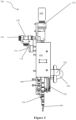
- FIG 1 shows a dosing apparatus 100 with an aromatherapy oil bottle 200 mounted thereon.
- the liquid is therefore aromatherapy oil in the embodiment being described, although the skilled person will appreciate that any liquid or mixture of liquids, including creams and gels, may take the place of the aromatherapy oil in other embodiments.
- bottles 200 or containers may be mounted, or a reservoir may be provided within the dosing apparatus 100 and an additive liquid may be poured into the reservoir, instead of mounting a separable container of the additive.
- the bottle 200 is mounted with its opening downwards so that gravity can assist draining of the bottle 200.
- Wastage may therefore be minimal, as the liquid drains from the bottle 200 by gravity by way of the bottle 200 being turned upside down with respect to its normal position.
- a bottle spring loaded (or otherwise urged using different mechanism) to provide a force on the liquid within towards the opening of the bottle could be used to allow the bottle to be loaded in the standard (upright, i.e. opening directed upwards) position whilst potentially reducing wastage as compared to suction pipe arrangements for upright bottles.
- An adapter 102 is provided, the adapter 102 being arranged to receive a neck of the bottle 200.
- the adapter 102 has a thread sized to match the thread on the neck of the bottle 200.
- the adapter thread allows the bottle 200 to be securely fitted to the adapter 102 and seals it in place.
- the bottle 200 is a standard aromatherapy oil/essential oil bottle - the present standard is standard DIN168 glass bottle vials and the adapter 102 of the present invention is sized and shaped for use with these bottles 200.
- adapter shape and dimensions may be adjusted to accommodate other bottle shapes and sizes.
- the bottle 200 is attached to the adapter 102 by rotating the thread of the bottle 200 into the adapter 102 until it meets a sealing face within the adapter 102.
- the adapter 102 then seals the inside of the bottle 200 from the outside air to prevent damage to its contents - which may be oils, scents, creams, medicated preparations, health or flavouring additives for drinking water, additives into tap water to aid shaving or wellness activities (e.g. steaming with menthol) etc.
- the neck of the bottle 200 is screwed into the adapter 102.
- the bottle 200 or other container may be a push-fit with the adapter 102, clipped, screwed or glued to the adapter 102, or connected in any other way.
- the adapter 102 may be integral with the container 200, the adapter 102 and container 200 together forming a detachable and replaceable cartridge 10 for use with the dosing apparatus 100.
- the cartridge 10 - either as a single unit or as a combination of a detachable adapter 102 and bottle 200 - provides a simple and convenient way of swapping additive liquids. A user may want multiple different additives at different stages of a shower, for example.
- the cartridge 10 may be easily removed and replaced, without removing the adapter 102 from the bottle 200.
- the adapter 102 serves as a lid for the bottle 200 when the bottle 200 is not connected to the dosing apparatus 100.
- the adapter 102 comprises an outlet 103.
- the outlet 103 is where the additive in the bottle 200 is dispensed from.
- the outlet 103 extends downwardly from and parallel to the length of the bottle. Gravity therefore assists in extracting as much of the liquid as reasonably possible from the bottle 200.
- the outlet 103 is also used to mount, orientate and seal the adapter 102 into the dosing apparatus 100.
- the outlet 103 comprises a hollow elongate projection, in this case a tube, arranged to fit within the apparatus 100 in the embodiment being described (in this case, within a pipe 130 of the apparatus), so as to facilitate the outlet's mounting and orientation functions.
- the outlet 103 comprises a passage with a one-way valve.
- the one-way valve is arranged to allow liquid within the bottle 200 to leave the bottle, and to prevent the return of liquid into the bottle.
- the outlet 103 may not have a one-way valve, and may instead be an unimpeded passage. In such cases, the passage is narrow (such that the liquid does not spill) and pressures are arranged such that the liquid will not pass through the outlet 103 unless drawn through, as described below.
- the adapter 102 comprises an air replenishment valve 105.
- the air replenishment valve 105 allows in air to replace the volume of liquid removed from the bottle 200, so preventing vacuum effects from retaining liquid within the bottle 200.
- the air replenishment valve 105 does not allow the passage of liquid therethrough.
- the air replenishment valve 105 is a one-way valve such that air cannot leave the bottle 200 via the air replenishment valve 105.
- a channel leads from the air replenishment valve 105 to the upper surface of the adapter 102, so providing a route for air to pass into the bottle 200, separate from the outlet 103.
- the air replenishment valve 105 is used in the adapter 102 to maintain a seal on the bottle 200 once it is fitted to the adapter 102. This valve 105 prevents the bottle's contents escaping, and also allows air into the bottle when the liquid is drawn down into the rest of the apparatus 100 for use, so as to prevent a hydraulic or vacuum lock.
- a small hole in an upper surface (in the orientation shown, i.e. the far end of the bottle from its opening) of the bottle 200 may be used instead of, or as well as, an air replenishment valve 105, and/or the air replenishment valve may be located differently with respect to the adapter 102 and bottle 200.
- a hole is provided instead of an air replenishment valve 105
- a one-way valve is provided in the outlet 103.
- the container 200 may or may not be compressible to reduce vacuum effects.
- the adapter 102 is connected to a housing 400 of the dosing apparatus.
- the adapter 102 is a push-fit with the housing 400 in this embodiment, and can be attached and detached in this way.
- formations 601 on one or more surfaces of the adapter 102 are provided to releasably interlock with corresponding formations on the housing 400.
- other connection means may be used, or the adapter 102 may be integral with the housing 400.
- the adapter 102 allows a user to rapidly change from one bottle 200 to another without switching the apparatus 100 off or unscrewing the bottle 200.
- the entire cartridge i.e. adapter 102 and bottle 200
- the bottle 200 fitted to the adapter 102 is exhausted, the bottle 200 can be removed from the adapter 102 and replaced or recharged.
- the dosing apparatus 100 comprises a dosing pump 104.
- the dosing pump 104 is located below the one-way valve 103 to facilitate drawing the liquid out of the bottle 200 and into the dosing pump 104.
- the dosing pump 104 has a dosing pump housing 104 which includes a docking member 132 arranged to receive the adapter 102.
- the adapter 102 is pushed into the top of the dosing pump housing 104, engaging with the docking member 132 and sealing the adapter 102 in place.
- the reservoir would take the place of the docking member 132.
- the dosing pump 104 has a barrel 109 and a dosing piston (not shown - covered by the dosing pump housing 104).
- a nozzle 107 extending from the barrel 109 provides a route for liquid to enter and leave the barrel 109.
- the barrel 109 forms a dosing chamber - a set volume (dose) of liquid is drawn out of the bottle 200 and into the barrel 109 when the apparatus 100 is activated.
- the dosing pump 104 has a dose button 150 which can be used to activate the apparatus 100, i.e. which is a dose activator.
- the dose button 150 is - directly or indirectly, electrically and/or mechanically - connected to the dosing piston.
- a slider or other control means, including an electronic interface such as a graphical user interface, may be provided in additional or alternative embodiments.
- the connected dosing pump piston When the dose button 150 is driven (manually or electro/mechanically driven), the connected dosing pump piston is moved away from the adapter 102, drawing a vacuum on the contents of the bottle 200.
- the suction/vacuum created is sufficient to open the air replenishment valve 105 in the adapter 102, allowing air to enter and the liquid in the bottle to fill the space in the dosing pump barrel 109.
- the suction applied therefore allows liquid to be drawn out of the bottle 200, with air passing into the bottle 200 via the air replenishment valve 105 to take its place. This can be thought of as a pressure differential between air near the inlet of the one-way valve and the outlet needing to exceed a threshold (with the pressure at the outlet being lower) for the liquid to pass through the outlet 103.
- the dose button 150 may be a push button, lever, rotatable knob, pull cord or other interface, including an electronic user interface, or any other suitable activation means.
- the skilled person will appreciate that, although the term “button” is used for clarity with reference to the drawings, any suitable interface known in the art may be used.
- the does button 150 may travel vertically or horizontally or at an angle with travel of movement appropriate for good ergonomic use, and that movement may be used to move the moveable member (in this case the dosing piston).
- the movement if any - there would be no movement for a graphical user interface "button" or activation of the button 150 causes an electrical signal which causes the moveable member to move, instead of moving it directly.
- the space is a set volume such that the same dose of liquid is taken in with each activation.
- the dose button 150 may be substituted with a different control means allowing adjustment of the set volume - the dosing pump piston can be drawn down by a differing amount so as to vary the amount of liquid taken from the bottle 200.
- the liquid from the bottle 200 remains in the dosing pump barrel 109 until the pump piston is driven (upwards) delivering the liquid through a dispensing outlet 170.
- the outlet 170 is connected to a water stream for dispersion in a shower, bath or faucet outlet.
- a pipe 130 provides a T-junction - the water stream enters through one opening 172 and leaves through a second opening 170, carrying with it the additive.
- the third branch of the T-junction is in fluid communication with, and adjacent to, the nozzle 107 and the bottle outlet 103.
- the outlet 170 may be arranged such that the liquid is dispensed onto an absorbent material, into a vessel, through a direct dispensing tube or onto a heat source, or the likes.
- the liquid In normal use, the liquid cannot be pushed back into the bottle 200 as the one-way valve and outlet system 103, 105 in the adapter 102 restricts any flow back into the bottle.
- the liquid from the barrel 109 flows through to the water stream as it is the path of least hydraulic resistance.
- a pipe 130 connects the adapter 102 to the nozzle 107 of the barrel 109.
- the pipe also connects the nozzle 107 to the outlet 170, which is a water stream in the embodiment shown.
- the nozzle 107 is located close to both the outlet 103 of the adapter 102 and the dispensing outlet 170; the length of the pipe 130 is therefore relatively short.
- this may help to minimise or avoid purging requirements to flush unused liquid out of the dosing apparatus 100.
- the rate at which the pump piston is driven back to its initial, pre-activation, position (i.e. upwards in the embodiment shown) is controlled by the damping control system 300.
- a connected hydraulic piston is similarly driven within a hydraulic charging chamber 108.
- the hydraulic piston when driven, moves a quantity of hydraulic fluid from the hydraulic charging chamber 108 into a passageway 114.
- the passageway is provided by a series of oilways and/or pipes/tubes 114 in the embodiment being described.
- a hydraulic filling port 180 is provided to allow the hydraulic fluid to be drained, replaced or topped up, as appropriate.
- the damping control system 300 uses and controls the movement of the hydraulic fluid so as to control the return rate of the pump piston, and hence the dosing rate.
- the damping control system 300 comprises four functional elements - a damping one-way valve 110, a sprung damping cylinder 106, a flow valve 112 and damping control setting 162.
- the one-way valve 110 allows the hydraulic fluid driven from the hydraulic charging chamber 108 to travel through the passageway 114 to the sprung damping cyclinder 106.
- the sprung damping cylinder 106 takes in the volume of displaced hydraulic fluid while creating a spring force to complete the return cycle of the dosing pump 104.
- the sprung damping cylinder 106 comprises a biasing member, in this case a spring (foam, another compressible elastic material, memory metal or an air bubble, etc. may be used in alternative or additional embodiments).
- the biasing member moves proportionally with the volume of hydraulic fluid displaced into the sprung damping cylinder 106. As the hydraulic fluid moves the spring, a force in the spring is created which is sufficient to return the hydraulic piston, and thereby the dosing piston, to its initial position, and therefore dispense the liquid via the dispensing outlet 170.
- the spring force acts upon the hydraulic fluid, driving it in the return direction.
- the hydraulic fluid is unable to return through the damping one-way valve 110 and is directed to a return channel including the flow valve 112 to limit the rate at which it can pass.
- the setting of the flow valve 112 can be adjusted to restrict or widen the return channel, so reducing or increasing the rate at which hydraulic fluid can pass therethrough, respectively.
- the fluid passing through the return channel enters the hydraulic charging chamber 108 and so moves the hydraulic piston back to its initial position at a rate corresponding to the flow rate through the flow valve 112.
- the flow valve 112 can be configured from a level of no restriction, and so near-immediate dispensing of the full dose, to a restriction slowing the dosing rate to extend over a duration desired for the application.
- aromatherapy oils for example, only a small amount of oil is needed for the desired effect, but the dispensing of this small amount is ideally performed over a relatively long time period (e.g. the several minutes taken to have a shower) rather than immediately.
- aromatherapy dosing will depend on the quality of the oil used and the user preference as to the strength of the scent.
- This user-set duration may range from 1 second to 30 seconds, to 1, 2, 4, 10, or 15 minutes, for example.
- a dispensing time of approximately 3 minutes may be selected for arometherapy oil release during a shower .
- the control may offer two or more discrete flow rate options or a continuous range.
- Desired duration is also likely to change depending on the chemistry of the liquid to be dispensed. For example, bleach in a toilet should be dispensed for a certain duration and in the correct volume to be at the correct concentration to be effective.
- the dosing duration in this application may be pre-set based on the relationship between the quantity of water used during a flushing activation and the appropriate chemical concentration required to be effective in its disinfection/cleaning task. An equivalent approach may apply to other alternative chemical dosing applications.
- the damping control setting 160, 162 allows the delivery time of the dosing apparatus to be configured.
- the dispensing rate is controlled by the piston movement, not by the flow rate of the water of the water stream into which the liquid is to be dispensed.
- the same quantity of liquid is dispensed over the controlled time period, although the additive liquid to water ratio would change depending on flow rate of the water.
- the damping control setting 160, 162 comprises a control dial 160 directly or indirectly connected to the flow valve 112.
- movement of the control dial 160 causes movement of a toothed wheel 162 which interlocks with a cog of the flow valve 112 so as to tighten or loosen the valve 112.
- control dial 160 is arranged to protrude through a housing 400 of the apparatus 100.
- the damping control system 300 is calibrated and the housing 400 is marked or labelled to indicate a dosing duration corresponding to each dial position.
- the flow valve 112 is an adjustable needle valve.
- a user of the apparatus 100 can adjust the damping control setting to a preferred or appropriate setting (e.g. corresponding to a duration of time) before the dose button 150 is driven.
- a preferred or appropriate setting e.g. corresponding to a duration of time
- no flow valve 112 and damping control setting 160, 162 may be provided.
- the return channel may comprise a narrow channel of a fixed size (e.g. simply a hole, or a non-adjustable needle valve) so as to limit return flow of the hydraulic fluid.
- the rate of return of the piston is therefore constant.
- the duration of the dosing is fixed for a given volume of hydraulic fluid displaced, and therefore for a given volume of liquid dispensed.
- a constant dosing rate (as compared to a constant duration) may therefore be provided for various different volumes of liquid, in embodiments in which the set volume can be adjusted.
- the damping control setting selected corresponds to the duration of time over which the dosing pump 104 will deliver the dose into the water stream.
- the dosing apparatus 100 is provided as a standalone box to be fittted to a standard shower or tap outlet.
- the box would be fitted between a shower control box and a shower head.
- the dosing apparatus 100 may be integrated into a shower control box. In either case, it may be used with hand-held showers and with wall- or ceiling-mounted showers (e.g. overhead showers).
- dose volume and time of delivery of each dose can be scaled for different applications.
- the duration of delivery of each dose is also scalable from instantaneous delivery to delivery over long periods of time.
- the system is designed to dose liquids, including gels and creams in this definition.
- Different viscosity materials may require different engineering details, e.g. different widths of the return channel, increased air pressure or a piston to remove bottle contents, etc., but can use the same principles.
- the dosing pump 104 can be located at a minimal distance from the dispensing outlet 170 (in the embodiment shown, the water stream). Any liquid is therefore delivered directly out of the dispensing outlet 170, in this case into the water stream.
- the dosing postomn may be replaced by a different moveable member, and the dosing piston barrel may be replaced with a different dosing chamber.
- the dosing chamber may be expansible (e.g. a balloon or the likes) and the moveable member may be a member that forces expansion of the dosing chamber when activated, so reducing pressure within the chamber and drawing the additive out of the container 200.
Landscapes
- Public Health (AREA)
- Health & Medical Sciences (AREA)
- Engineering & Computer Science (AREA)
- Life Sciences & Earth Sciences (AREA)
- Hydrology & Water Resources (AREA)
- Water Supply & Treatment (AREA)
- Epidemiology (AREA)
- General Engineering & Computer Science (AREA)
- Mechanical Engineering (AREA)
- General Health & Medical Sciences (AREA)
- Containers And Packaging Bodies Having A Special Means To Remove Contents (AREA)
- Devices For Dispensing Beverages (AREA)
- Bidet-Like Cleaning Device And Other Flush Toilet Accessories (AREA)
- Feeding, Discharge, Calcimining, Fusing, And Gas-Generation Devices (AREA)
- Catching Or Destruction (AREA)
Applications Claiming Priority (3)
| Application Number | Priority Date | Filing Date | Title |
|---|---|---|---|
| GB1710233.6A GB2553031B (en) | 2017-06-27 | 2017-06-27 | Additive dispenser |
| EP18739581.9A EP3645797B1 (fr) | 2017-06-27 | 2018-06-26 | Distributeur d'additif |
| PCT/GB2018/051782 WO2019002845A1 (fr) | 2017-06-27 | 2018-06-26 | Distributeur d'additif |
Related Parent Applications (2)
| Application Number | Title | Priority Date | Filing Date |
|---|---|---|---|
| EP18739581.9A Division EP3645797B1 (fr) | 2017-06-27 | 2018-06-26 | Distributeur d'additif |
| EP18739581.9A Division-Into EP3645797B1 (fr) | 2017-06-27 | 2018-06-26 | Distributeur d'additif |
Publications (2)
| Publication Number | Publication Date |
|---|---|
| EP4257763A2 true EP4257763A2 (fr) | 2023-10-11 |
| EP4257763A3 EP4257763A3 (fr) | 2023-12-27 |
Family
ID=59523454
Family Applications (2)
| Application Number | Title | Priority Date | Filing Date |
|---|---|---|---|
| EP18739581.9A Active EP3645797B1 (fr) | 2017-06-27 | 2018-06-26 | Distributeur d'additif |
| EP23192788.0A Pending EP4257763A3 (fr) | 2017-06-27 | 2018-06-26 | Distributeur d'additif |
Family Applications Before (1)
| Application Number | Title | Priority Date | Filing Date |
|---|---|---|---|
| EP18739581.9A Active EP3645797B1 (fr) | 2017-06-27 | 2018-06-26 | Distributeur d'additif |
Country Status (5)
| Country | Link |
|---|---|
| US (3) | US11230833B2 (fr) |
| EP (2) | EP3645797B1 (fr) |
| CN (2) | CN110709565B (fr) |
| GB (1) | GB2553031B (fr) |
| WO (1) | WO2019002845A1 (fr) |
Families Citing this family (3)
| Publication number | Priority date | Publication date | Assignee | Title |
|---|---|---|---|---|
| GB2553031B (en) | 2017-06-27 | 2021-12-29 | Kohler Mira Ltd | Additive dispenser |
| US11666931B2 (en) | 2019-05-14 | 2023-06-06 | Kohler Co. | Inline shower device |
| WO2022182218A1 (fr) * | 2021-02-23 | 2022-09-01 | Gutierrez Ibanez Joel | Système, procédé et composants pour fournir des produits consommables dans un emballage réutilisable |
Family Cites Families (56)
| Publication number | Priority date | Publication date | Assignee | Title |
|---|---|---|---|---|
| US2564618A (en) * | 1949-08-04 | 1951-08-14 | Harold M Williams | Soap solution dispenser |
| US3106345A (en) | 1961-06-14 | 1963-10-08 | Wukowitz Edward | Shower bath water control with additive attachment |
| US3890657A (en) * | 1974-05-16 | 1975-06-24 | Roy M Gray | Chemical dispenser for toilet |
| DE2529156C3 (de) | 1975-06-30 | 1980-03-06 | Hans Joachim 6451 Bruchkoebel Mohn | Vorrichtung zur dosierbaren Beimengung von einer Duft-Schaumlösung zu fließendem Wasser |
| US4085868A (en) | 1976-09-01 | 1978-04-25 | Robert Lynn Blair | Bath oil injection device for shower bath |
| GB2019235B (en) | 1978-03-03 | 1982-06-30 | Hexagear Ind Ltd | Bath oil dispensers |
| US4225085A (en) | 1979-03-29 | 1980-09-30 | James J. Headen | Shower head dispenser |
| US4432105A (en) | 1981-11-18 | 1984-02-21 | Pitroda Pravin G | Shower device |
| US5004158A (en) * | 1989-08-21 | 1991-04-02 | Stephen Halem | Fluid dispensing and mixing device |
| US5071070A (en) | 1989-09-21 | 1991-12-10 | Hardy Duard I | Apparatus for dispensing fluid into the water flow of a shower |
| US4971105A (en) * | 1990-01-16 | 1990-11-20 | Mcguire George E | Hydraulic fluid injection apparatus |
| US5404594A (en) * | 1993-04-05 | 1995-04-11 | Ring; Russel F. | In-line toilet bowl cleaner apparatus |
| AU4233697A (en) * | 1996-08-06 | 1998-02-25 | Lancer Partnership, Ltd. | Flow control system for dispensers |
| US6045060A (en) | 1997-03-19 | 2000-04-04 | Hudson; Donald D. | Liquid soap mixer for showerheads |
| DE19744063C2 (de) | 1997-10-06 | 2000-02-24 | Rolf Ideus | Armatur für einen Haushaltssanitärbereich zum Beimischen eines Zusatzmittels zum fließenden Leitungswasser |
| US6006374A (en) | 1998-09-23 | 1999-12-28 | Winnett; Harold G. | Showerhead attachment and method for generating aromas |
| EP1020233A1 (fr) * | 1999-01-13 | 2000-07-19 | The Procter & Gamble Company | Système de dosage et de distribution |
| AUPQ138899A0 (en) | 1999-07-05 | 1999-07-29 | Gent, Nicholas Van | Sanitary apparatus |
| US6419166B1 (en) * | 2000-04-28 | 2002-07-16 | Stan F. Brzezinski | Dispenser to liquid stream |
| US20020070292A1 (en) | 2000-11-10 | 2002-06-13 | Hazenfield David S. | Cleaning liquid dispensing apparatus for a shower head |
| DE10112245A1 (de) | 2001-04-25 | 2002-11-07 | Werner Schlimper | Duscheinrichtung |
| US6851626B2 (en) | 2002-01-07 | 2005-02-08 | Aerogen, Inc. | Methods and devices for nebulizing fluids |
| JP4761709B2 (ja) | 2002-01-15 | 2011-08-31 | エアロジェン,インコーポレイテッド | エアロゾル発生器を作動するための方法およびシステム |
| US6868992B2 (en) * | 2002-08-13 | 2005-03-22 | Jacob Lasry | Liquid-dispensing device |
| US7156324B2 (en) | 2003-11-13 | 2007-01-02 | Oms Investments, Inc. | Spraying device with interchangeable cartridge |
| US7905429B2 (en) | 2005-10-18 | 2011-03-15 | Water Pik, Inc. | Dispensing system and method for shower arm |
| GB0610666D0 (en) * | 2006-05-30 | 2006-07-05 | Glaxo Group Ltd | Fluid dispenser |
| US8544698B2 (en) * | 2007-03-26 | 2013-10-01 | Gojo Industries, Inc. | Foam soap dispenser with stationary dispensing tube |
| US8070074B2 (en) | 2008-04-30 | 2011-12-06 | William Richard Craig | Bathing apparatus and method of using same |
| ATE514820T1 (de) | 2008-12-30 | 2011-07-15 | Urs Straeuli | Vorrichtung und verfahren zur verwendung in einem dusch-system |
| US20110073137A1 (en) | 2009-09-28 | 2011-03-31 | John James Dvorak | Shower Sanitization System and Apparatus |
| CN102031675B (zh) * | 2009-09-28 | 2012-01-11 | 杭州神林电子有限公司 | 液体洗涤剂投放装置 |
| EP2363539B1 (fr) | 2010-03-01 | 2012-05-23 | Urs Sträuli | Dispositif et procédé d'utilisation pour soins corporels, notamment pour la douche, le bain ou le lavage des mains |
| US8820660B2 (en) | 2010-10-18 | 2014-09-02 | Adebowale Ajagbe | Aromatic shower head device |
| EP2543779A3 (fr) | 2011-07-07 | 2015-05-06 | Markon Holdings Limited | Système de mélange d'eau, robinetterie sanitaire, système de remplissage de bain et système pour introduire sélectivement un additif dans un courant d'eau |
| US9127391B2 (en) | 2011-08-17 | 2015-09-08 | General Electric Company | Device for dispensing an additive in an appliance |
| US9094569B1 (en) | 2012-02-01 | 2015-07-28 | Gary James Humphries | Remote web-based visitation system for prisons |
| FR2996568B1 (fr) | 2012-10-04 | 2018-03-16 | Skinjay | Dispositif de diffusion d'un produit dans de l'eau |
| CN102989605B (zh) | 2012-11-15 | 2015-06-17 | 厦门松霖科技有限公司 | 香熏花洒 |
| US8800891B2 (en) | 2012-12-04 | 2014-08-12 | Mengfeng Cheng | Shower soap dispenser and cartridge |
| US9556969B2 (en) * | 2013-04-05 | 2017-01-31 | Hirohiko Sato | Valve device and shower device using the same |
| FR3005073B1 (fr) | 2013-04-26 | 2015-05-29 | Challengine | Dispositif de diffusion d'un produit encapsule dans un flux d'eau |
| US9079204B1 (en) | 2013-06-10 | 2015-07-14 | Troy C. Hattenbrun | Showerhead cleaning adapter |
| CN103551272B (zh) | 2013-11-07 | 2017-11-10 | 厦门松霖科技股份有限公司 | 具附加功能的出水机构 |
| CN204199384U (zh) * | 2014-09-10 | 2015-03-11 | 李志刚 | 一种自来水末端液剂自动加注装置 |
| CN104372829B (zh) * | 2014-09-10 | 2017-02-08 | 李志刚 | 一种自来水末端液剂自动加注装置 |
| US9521898B2 (en) * | 2014-09-30 | 2016-12-20 | Nickholas Knight | Shower brush having interchangeable cleaning attachments |
| WO2017201716A1 (fr) | 2016-05-26 | 2017-11-30 | 惠州市吉瑞科技有限公司深圳分公司 | Bouteille de stockage de liquide et ensemble bouteille de stockage de liquide |
| CN205676979U (zh) * | 2016-05-27 | 2016-11-09 | 码头铺镇中学 | 一种自带洗手液和发电的水龙头 |
| CN206120177U (zh) * | 2016-08-09 | 2017-04-26 | 江门市爱威特电器有限公司 | 一种自动皂液器 |
| CN106829176A (zh) * | 2016-12-29 | 2017-06-13 | 天津效岩科技有限公司 | 一种液体容器的定量装置 |
| FR3062552B1 (fr) | 2017-02-09 | 2021-03-05 | Skinjay | Dispositif de diffusion d'un produit encapsule dans un fluide |
| GB2553031B (en) | 2017-06-27 | 2021-12-29 | Kohler Mira Ltd | Additive dispenser |
| US11866917B2 (en) * | 2017-06-30 | 2024-01-09 | Gjosa Sa | Apparatus for dispensing a mixture of a diluent and an additive for sanitation, cosmetic or cleaning applications |
| US20190093324A1 (en) * | 2017-09-28 | 2019-03-28 | Alan Backus | System and method for fluid handling in a shower or bath |
| US20220234062A1 (en) | 2019-05-31 | 2022-07-28 | Graco Minnesota Inc. | Handheld fluid sprayer |
-
2017
- 2017-06-27 GB GB1710233.6A patent/GB2553031B/en active Active
-
2018
- 2018-06-26 WO PCT/GB2018/051782 patent/WO2019002845A1/fr unknown
- 2018-06-26 CN CN201880034837.4A patent/CN110709565B/zh active Active
- 2018-06-26 CN CN202011370617.4A patent/CN112524298B/zh active Active
- 2018-06-26 EP EP18739581.9A patent/EP3645797B1/fr active Active
- 2018-06-26 EP EP23192788.0A patent/EP4257763A3/fr active Pending
-
2019
- 2019-12-13 US US16/713,658 patent/US11230833B2/en active Active
-
2021
- 2021-12-14 US US17/550,573 patent/US11773577B2/en active Active
-
2023
- 2023-08-30 US US18/458,724 patent/US20230407615A1/en active Pending
Also Published As
| Publication number | Publication date |
|---|---|
| GB201710233D0 (en) | 2017-08-09 |
| US20220098844A1 (en) | 2022-03-31 |
| CN112524298B (zh) | 2022-08-19 |
| EP3645797A1 (fr) | 2020-05-06 |
| GB2553031A (en) | 2018-02-21 |
| WO2019002845A1 (fr) | 2019-01-03 |
| EP4257763A3 (fr) | 2023-12-27 |
| US11230833B2 (en) | 2022-01-25 |
| CN112524298A (zh) | 2021-03-19 |
| CN110709565A (zh) | 2020-01-17 |
| US11773577B2 (en) | 2023-10-03 |
| CN110709565B (zh) | 2021-07-20 |
| GB2553031B (en) | 2021-12-29 |
| US20200131750A1 (en) | 2020-04-30 |
| US20230407615A1 (en) | 2023-12-21 |
| EP3645797B1 (fr) | 2023-10-11 |
Similar Documents
| Publication | Publication Date | Title |
|---|---|---|
| US11773577B2 (en) | Additive dispenser | |
| US6006374A (en) | Showerhead attachment and method for generating aromas | |
| US5584079A (en) | Programmable dispenser | |
| CA2945378C (fr) | Mini-pompe comportant une chambre d'entree d'air comprimable pour fournir une aspiration inverse | |
| US20150090737A1 (en) | Dispensers, refill units and pumps having suck-back features | |
| JP5469093B2 (ja) | オンタンク式トイレディスペンサ | |
| EP2089118A2 (fr) | Distributeur d'additif pour douche | |
| US8631519B1 (en) | Toilet cleanser and deodorizer dispenser | |
| KR20000069481A (ko) | 투여하는 장치 및 방법과 밸브 | |
| AU2013280697B2 (en) | Grit and foam dispenser | |
| US20070246486A1 (en) | Conversion Kit to Retrofit Kitchen Sink Soap Dispenser to a Liquid Soap Bottle | |
| CA2359020A1 (fr) | Distributeur passif servant a doser et a liberer une quantite predeterminee d'un liquide distribuable | |
| KR101949333B1 (ko) | 물비누 보충이 용이한 수전 | |
| EP1721049B1 (fr) | Systeme de generation de mousse | |
| WO2006117790A1 (fr) | Procede et systeme comportant un reservoir pouvant etre rempli et destine a ajouter des produits chimiques solides ou liquides dans l'eau de chasse des toilettes | |
| US20050023303A1 (en) | Metering tap | |
| GB2478141A (en) | A dispenser comprising a spray head and a pouring outlet | |
| GB2441757A (en) | Dispensing Device | |
| KR20140004717U (ko) | 포세식 변기의 세정액 정량공급장치 | |
| WO2008110839A3 (fr) | Distributeur | |
| CA2568101A1 (fr) | Dispositif pour la distribution d'une quantite mesuree de liquide dans une cuvette de cabinet d'aisance immediatement avant de l'utiliser pour le controle des mauvaises odeurs liees aux selles et a d'autres fluides corporels |
Legal Events
| Date | Code | Title | Description |
|---|---|---|---|
| PUAI | Public reference made under article 153(3) epc to a published international application that has entered the european phase |
Free format text: ORIGINAL CODE: 0009012 |
|
| STAA | Information on the status of an ep patent application or granted ep patent |
Free format text: STATUS: THE APPLICATION HAS BEEN PUBLISHED |
|
| AC | Divisional application: reference to earlier application |
Ref document number: 3645797 Country of ref document: EP Kind code of ref document: P |
|
| AK | Designated contracting states |
Kind code of ref document: A2 Designated state(s): AL AT BE BG CH CY CZ DE DK EE ES FI FR GB GR HR HU IE IS IT LI LT LU LV MC MK MT NL NO PL PT RO RS SE SI SK SM TR |
|
| REG | Reference to a national code |
Ref country code: DE Ref legal event code: R079 Free format text: PREVIOUS MAIN CLASS: E03D0009020000 Ipc: E03C0001046000 |
|
| PUAL | Search report despatched |
Free format text: ORIGINAL CODE: 0009013 |
|
| STAA | Information on the status of an ep patent application or granted ep patent |
Free format text: STATUS: REQUEST FOR EXAMINATION WAS MADE |
|
| AK | Designated contracting states |
Kind code of ref document: A3 Designated state(s): AL AT BE BG CH CY CZ DE DK EE ES FI FR GB GR HR HU IE IS IT LI LT LU LV MC MK MT NL NO PL PT RO RS SE SI SK SM TR |
|
| RIC1 | Information provided on ipc code assigned before grant |
Ipc: E03D 9/02 20060101ALI20231120BHEP Ipc: E03C 1/046 20060101AFI20231120BHEP |
|
| 17P | Request for examination filed |
Effective date: 20231128 |
|
| RBV | Designated contracting states (corrected) |
Designated state(s): AL AT BE BG CH CY CZ DE DK EE ES FI FR GB GR HR HU IE IS IT LI LT LU LV MC MK MT NL NO PL PT RO RS SE SI SK SM TR |
|
| GRAP | Despatch of communication of intention to grant a patent |
Free format text: ORIGINAL CODE: EPIDOSNIGR1 |
|
| STAA | Information on the status of an ep patent application or granted ep patent |
Free format text: STATUS: GRANT OF PATENT IS INTENDED |
|
| INTG | Intention to grant announced |
Effective date: 20240320 |
|
| GRAS | Grant fee paid |
Free format text: ORIGINAL CODE: EPIDOSNIGR3 |