EP4256276B1 - Positionssensor mit variabler reluktanz - Google Patents
Positionssensor mit variabler reluktanz Download PDFInfo
- Publication number
- EP4256276B1 EP4256276B1 EP21824420.0A EP21824420A EP4256276B1 EP 4256276 B1 EP4256276 B1 EP 4256276B1 EP 21824420 A EP21824420 A EP 21824420A EP 4256276 B1 EP4256276 B1 EP 4256276B1
- Authority
- EP
- European Patent Office
- Prior art keywords
- magnetic sensor
- sensor sections
- group
- variable reluctance
- sections
- Prior art date
- Legal status (The legal status is an assumption and is not a legal conclusion. Google has not performed a legal analysis and makes no representation as to the accuracy of the status listed.)
- Active
Links
Images


Classifications
-
- G—PHYSICS
- G01—MEASURING; TESTING
- G01D—MEASURING NOT SPECIALLY ADAPTED FOR A SPECIFIC VARIABLE; ARRANGEMENTS FOR MEASURING TWO OR MORE VARIABLES NOT COVERED IN A SINGLE OTHER SUBCLASS; TARIFF METERING APPARATUS; MEASURING OR TESTING NOT OTHERWISE PROVIDED FOR
- G01D5/00—Mechanical means for transferring the output of a sensing member; Means for converting the output of a sensing member to another variable where the form or nature of the sensing member does not constrain the means for converting; Transducers not specially adapted for a specific variable
- G01D5/12—Mechanical means for transferring the output of a sensing member; Means for converting the output of a sensing member to another variable where the form or nature of the sensing member does not constrain the means for converting; Transducers not specially adapted for a specific variable using electric or magnetic means
- G01D5/14—Mechanical means for transferring the output of a sensing member; Means for converting the output of a sensing member to another variable where the form or nature of the sensing member does not constrain the means for converting; Transducers not specially adapted for a specific variable using electric or magnetic means influencing the magnitude of a current or voltage
- G01D5/20—Mechanical means for transferring the output of a sensing member; Means for converting the output of a sensing member to another variable where the form or nature of the sensing member does not constrain the means for converting; Transducers not specially adapted for a specific variable using electric or magnetic means influencing the magnitude of a current or voltage by varying inductance, e.g. by a movable armature
- G01D5/204—Mechanical means for transferring the output of a sensing member; Means for converting the output of a sensing member to another variable where the form or nature of the sensing member does not constrain the means for converting; Transducers not specially adapted for a specific variable using electric or magnetic means influencing the magnitude of a current or voltage by varying inductance, e.g. by a movable armature by influencing the mutual induction between two or more coils
-
- G—PHYSICS
- G01—MEASURING; TESTING
- G01B—MEASURING LENGTH, THICKNESS OR SIMILAR LINEAR DIMENSIONS; MEASURING ANGLES; MEASURING AREAS; MEASURING IRREGULARITIES OF SURFACES OR CONTOURS
- G01B7/00—Measuring arrangements characterised by the use of electric or magnetic techniques
- G01B7/30—Measuring arrangements characterised by the use of electric or magnetic techniques for measuring angles or tapers; for testing the alignment of axes
-
- G—PHYSICS
- G01—MEASURING; TESTING
- G01B—MEASURING LENGTH, THICKNESS OR SIMILAR LINEAR DIMENSIONS; MEASURING ANGLES; MEASURING AREAS; MEASURING IRREGULARITIES OF SURFACES OR CONTOURS
- G01B7/00—Measuring arrangements characterised by the use of electric or magnetic techniques
- G01B7/003—Measuring arrangements characterised by the use of electric or magnetic techniques for measuring position, not involving coordinate determination
-
- G—PHYSICS
- G01—MEASURING; TESTING
- G01D—MEASURING NOT SPECIALLY ADAPTED FOR A SPECIFIC VARIABLE; ARRANGEMENTS FOR MEASURING TWO OR MORE VARIABLES NOT COVERED IN A SINGLE OTHER SUBCLASS; TARIFF METERING APPARATUS; MEASURING OR TESTING NOT OTHERWISE PROVIDED FOR
- G01D5/00—Mechanical means for transferring the output of a sensing member; Means for converting the output of a sensing member to another variable where the form or nature of the sensing member does not constrain the means for converting; Transducers not specially adapted for a specific variable
- G01D5/12—Mechanical means for transferring the output of a sensing member; Means for converting the output of a sensing member to another variable where the form or nature of the sensing member does not constrain the means for converting; Transducers not specially adapted for a specific variable using electric or magnetic means
- G01D5/14—Mechanical means for transferring the output of a sensing member; Means for converting the output of a sensing member to another variable where the form or nature of the sensing member does not constrain the means for converting; Transducers not specially adapted for a specific variable using electric or magnetic means influencing the magnitude of a current or voltage
- G01D5/20—Mechanical means for transferring the output of a sensing member; Means for converting the output of a sensing member to another variable where the form or nature of the sensing member does not constrain the means for converting; Transducers not specially adapted for a specific variable using electric or magnetic means influencing the magnitude of a current or voltage by varying inductance, e.g. by a movable armature
- G01D5/204—Mechanical means for transferring the output of a sensing member; Means for converting the output of a sensing member to another variable where the form or nature of the sensing member does not constrain the means for converting; Transducers not specially adapted for a specific variable using electric or magnetic means influencing the magnitude of a current or voltage by varying inductance, e.g. by a movable armature by influencing the mutual induction between two or more coils
- G01D5/2046—Mechanical means for transferring the output of a sensing member; Means for converting the output of a sensing member to another variable where the form or nature of the sensing member does not constrain the means for converting; Transducers not specially adapted for a specific variable using electric or magnetic means influencing the magnitude of a current or voltage by varying inductance, e.g. by a movable armature by influencing the mutual induction between two or more coils by a movable ferromagnetic element, e.g. a core
-
- G—PHYSICS
- G01—MEASURING; TESTING
- G01D—MEASURING NOT SPECIALLY ADAPTED FOR A SPECIFIC VARIABLE; ARRANGEMENTS FOR MEASURING TWO OR MORE VARIABLES NOT COVERED IN A SINGLE OTHER SUBCLASS; TARIFF METERING APPARATUS; MEASURING OR TESTING NOT OTHERWISE PROVIDED FOR
- G01D5/00—Mechanical means for transferring the output of a sensing member; Means for converting the output of a sensing member to another variable where the form or nature of the sensing member does not constrain the means for converting; Transducers not specially adapted for a specific variable
- G01D5/12—Mechanical means for transferring the output of a sensing member; Means for converting the output of a sensing member to another variable where the form or nature of the sensing member does not constrain the means for converting; Transducers not specially adapted for a specific variable using electric or magnetic means
- G01D5/14—Mechanical means for transferring the output of a sensing member; Means for converting the output of a sensing member to another variable where the form or nature of the sensing member does not constrain the means for converting; Transducers not specially adapted for a specific variable using electric or magnetic means influencing the magnitude of a current or voltage
- G01D5/20—Mechanical means for transferring the output of a sensing member; Means for converting the output of a sensing member to another variable where the form or nature of the sensing member does not constrain the means for converting; Transducers not specially adapted for a specific variable using electric or magnetic means influencing the magnitude of a current or voltage by varying inductance, e.g. by a movable armature
- G01D5/22—Mechanical means for transferring the output of a sensing member; Means for converting the output of a sensing member to another variable where the form or nature of the sensing member does not constrain the means for converting; Transducers not specially adapted for a specific variable using electric or magnetic means influencing the magnitude of a current or voltage by varying inductance, e.g. by a movable armature differentially influencing two coils
- G01D5/2291—Linear or rotary variable differential transformers (LVDTs/RVDTs) having a single primary coil and two secondary coils
-
- G—PHYSICS
- G01—MEASURING; TESTING
- G01D—MEASURING NOT SPECIALLY ADAPTED FOR A SPECIFIC VARIABLE; ARRANGEMENTS FOR MEASURING TWO OR MORE VARIABLES NOT COVERED IN A SINGLE OTHER SUBCLASS; TARIFF METERING APPARATUS; MEASURING OR TESTING NOT OTHERWISE PROVIDED FOR
- G01D5/00—Mechanical means for transferring the output of a sensing member; Means for converting the output of a sensing member to another variable where the form or nature of the sensing member does not constrain the means for converting; Transducers not specially adapted for a specific variable
- G01D5/12—Mechanical means for transferring the output of a sensing member; Means for converting the output of a sensing member to another variable where the form or nature of the sensing member does not constrain the means for converting; Transducers not specially adapted for a specific variable using electric or magnetic means
- G01D5/244—Mechanical means for transferring the output of a sensing member; Means for converting the output of a sensing member to another variable where the form or nature of the sensing member does not constrain the means for converting; Transducers not specially adapted for a specific variable using electric or magnetic means influencing characteristics of pulses or pulse trains; generating pulses or pulse trains
-
- G—PHYSICS
- G01—MEASURING; TESTING
- G01P—MEASURING LINEAR OR ANGULAR SPEED, ACCELERATION, DECELERATION, OR SHOCK; INDICATING PRESENCE, ABSENCE, OR DIRECTION, OF MOVEMENT
- G01P3/00—Measuring linear or angular speed; Measuring differences of linear or angular speeds
- G01P3/42—Devices characterised by the use of electric or magnetic means
- G01P3/44—Devices characterised by the use of electric or magnetic means for measuring angular speed
- G01P3/48—Devices characterised by the use of electric or magnetic means for measuring angular speed by measuring frequency of generated current or voltage
- G01P3/481—Devices characterised by the use of electric or magnetic means for measuring angular speed by measuring frequency of generated current or voltage of pulse signals
- G01P3/488—Devices characterised by the use of electric or magnetic means for measuring angular speed by measuring frequency of generated current or voltage of pulse signals delivered by variable reluctance detectors
-
- G—PHYSICS
- G01—MEASURING; TESTING
- G01R—MEASURING ELECTRIC VARIABLES; MEASURING MAGNETIC VARIABLES
- G01R33/00—Arrangements or instruments for measuring magnetic variables
- G01R33/0005—Geometrical arrangement of magnetic sensor elements; Apparatus combining different magnetic sensor types
-
- H—ELECTRICITY
- H02—GENERATION; CONVERSION OR DISTRIBUTION OF ELECTRIC POWER
- H02K—DYNAMO-ELECTRIC MACHINES
- H02K1/00—Details of the magnetic circuit
- H02K1/06—Details of the magnetic circuit characterised by the shape, form or construction
- H02K1/22—Rotating parts of the magnetic circuit
- H02K1/24—Rotor cores with salient poles ; Variable reluctance rotors
- H02K1/246—Variable reluctance rotors
-
- H—ELECTRICITY
- H02—GENERATION; CONVERSION OR DISTRIBUTION OF ELECTRIC POWER
- H02K—DYNAMO-ELECTRIC MACHINES
- H02K11/00—Structural association of dynamo-electric machines with electric components or with devices for shielding, monitoring or protection
- H02K11/20—Structural association of dynamo-electric machines with electric components or with devices for shielding, monitoring or protection for measuring, monitoring, testing, protecting or switching
- H02K11/21—Devices for sensing speed or position, or actuated thereby
- H02K11/215—Magnetic effect devices, e.g. Hall-effect or magneto-resistive elements
-
- H—ELECTRICITY
- H02—GENERATION; CONVERSION OR DISTRIBUTION OF ELECTRIC POWER
- H02K—DYNAMO-ELECTRIC MACHINES
- H02K11/00—Structural association of dynamo-electric machines with electric components or with devices for shielding, monitoring or protection
- H02K11/20—Structural association of dynamo-electric machines with electric components or with devices for shielding, monitoring or protection for measuring, monitoring, testing, protecting or switching
- H02K11/21—Devices for sensing speed or position, or actuated thereby
- H02K11/225—Detecting coils
Definitions
- variable reluctance position sensor that can be, for example not necessarily, a variable reluctance resolver for producing signals indicative of a rotation angle of a rotating object such as e.g. a rotor of an electric machine.
- the variable reluctance position sensor can be a sensor configured measure a position of a moving object such as e.g. a mover of a linear electric machine.
- a variable reluctance "VR" position sensor comprises excitation coils and detection coils in a first element and no coils in a second element which is movable with respect to the first element and whose position with respect to the first element is to be measured. Thus, there is no need to conduct electric current to the moving second element.
- a variable reluctance position sensor can be for example a variable reluctance resolver in which the above-mentioned first element is a stator and the above-mentioned second element is a rotor whose rotation angle with respect to the stator is to be measured.
- a significant advantage of a variable reluctance resolver is that there is no need to conduct electric current to the rotor.
- a stator of a variable reluctance resolver receives an alternating excitation signal to excitation coils and produces first and second alternating output signals by first and second detection coils, respectively, wherein amplitudes of the first and second alternating output signals are dependent on the rotational position of the resolver so that envelopes of the first and second alternating output signals i.e. curves outlining extremes of the first and second alternating output signals have a mutual phase shift.
- the publication US20130162243 describes a variable reluctance resolver that comprises a ring-like stator, a rotor, and a housing.
- the stator comprises a stator core and coils.
- the stator core is provided with plural salient poles.
- the coils are wound to the salient poles of the stator.
- the housing accommodates the stator.
- the rotor comprises an airgap surface having a profile formed with plural arc-like convex portions that deviate from a circular shape and are located at equal spaces in the circumferential direction.
- the number of the arc-like convex portions is the ratio of 360 degrees, i.e. a full circle, to the center angle of a measurement sector of the variable reluctance resolver.
- the number of the above-mentioned arc-like convex portions can be e.g. the same as the number of pole-pairs of the electric machine, and thereby the variable reluctance resolver measures the rotational position of the rotor of the electric machine as electrical degrees. It is also possible that the number of pole-pairs of the electric machine is a multiple of the number of the arc-like convex portions. In this exemplifying case, the angle measured with the variable reluctance resolver is to be multiplied by this multiple number to obtain the rotational position of the rotor of the electric machine as electrical degrees of the electric machine.
- a variable reluctance resolver of the kind described above is however not free from challenges.
- One of the challenges is related to cases in which a variable reluctance resolver is used for measuring a rotation angle of a rotor of an electric machine that has very many pole-pairs.
- the center angle of a measurement sector of the variable reluctance resolver is small in mechanical degrees and thus the pole pitch in the stator of the variable reluctance resolver must be small in mechanical degrees to achieve a sufficient measurement accuracy in electrical degrees.
- EP 3 324 523 A1 , US 2004/007926 A1 and US 2019/280537 A1 are further known examples of variable reluctance position sensors.
- geometric when used as a prefix means a geometric concept that is not necessarily a part of any physical object.
- the geometric concept can be for example a geometric point, a straight or curved geometric line, a planar or non-planar geometric surface, a geometric space, or any other geometric entity that is zero, one, two, or three dimensional.
- variable reluctance position sensor that can be for example a variable reluctance resolver for measuring a rotational angle of a rotating object. It is however also possible that a variable reluctance position sensor according to an embodiment of the invention is configured to measure a position of a linearly moving object.
- a variable reluctance position sensor comprises:
- the above-mentioned first ones of the magnetic sensor sections constitute a first group of successively placed magnetic sensor sections and the above-mentioned second ones of the magnetic sensor sections constitute a second group of successively placed magnetic sensor sections so that the second group is displaced with respect to the first group by C ⁇ the spatial meandering period, where C is a non-integer number.
- C 1 ⁇ 4 + an integer
- the phase-shift between the envelopes of the first and second alternating output signals is 90 degrees, i.e. ⁇ /2.
- the first group of successively placed magnetic sensor sections covers less than the spatial meandering period, and correspondingly the second group of successively placed magnetic sensor sections covers less than the spatial meandering period.
- the first group of successively placed magnetic sensor sections covers less than 2 ⁇ the spatial meandering period, and correspondingly the second group of successively placed magnetic sensor sections covers less than 2 ⁇ the spatial meandering period.
- variable reluctance position sensor is a variable reluctance resolver that is used for measuring a rotational angle of an electric machine having many pole-pairs
- the stator of the variable reluctance resolver does not need to cover 360 mechanical degrees, but the first group of successively placed magnetic sensor sections covers advantageously less than one pole pair pitch, i.e. less than 360 electrical degrees, of the electric machine and correspondingly the second group of successively placed magnetic sensor sections covers advantageously less than one pole pair pitch of the electric machine.
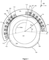
- FIG. 1 illustrates a variable reluctance position sensor according to an exemplifying and non-limiting embodiment.
- the variable reluctance position sensor comprises a first element 101 and a second element 104.
- the variable reluctance position sensor is a variable reluctance resolver for measuring a rotational angle ⁇ of the second element 104 with respect to the first element 101.
- the rotational axis of the second element 104 i.e. a rotor, is parallel with the z-axis of a coordinate system 199.
- the second element 104 i.e. the rotor, comprises an air-gap surface 105 that has a periodically meandering profile with four spatial meandering periods.
- the first element 101 i.e. a stator
- the first element 101 comprises a plurality of magnetic sensor sections that are placed along an arc of a geometric circle in a direction of movement of the airgap surface 105.
- two of the magnetic sensor sections are denoted with references 102 and 103.
- the profile of the air-gap surface 105 meanders with respect to a geometric circle 116 so that a radius r is a periodic function of a center angle ⁇ that is defined with respect to a reference direction fixed to the second element 104.
- a part 120 of the second element 104 may comprise electrically insulated ferromagnetic sheets stacked in the axial direction of the second element 104, i.e. in the z-direction of the coordinate system 199. It is also possible that the part 120 is made of e.g. ferrite or soft magnetic composite such as e.g. SOMALOY ® .
- a center part 121 of the second element 104 can be made of e.g. solid steel.
- Each of the magnetic sensor sections of the first element 101 is configured to conduct a magnetic flux to and from the second element 104 via the airgap surface 105 of the second element.
- First ones of the magnetic sensor sections constitute a first group 110 of equidistantly successively placed magnetic sensor sections and second ones of the magnetic sensor sections constitute a second group 111 of equidistantly successively placed magnetic sensor sections.
- the first ones of the magnetic sensor sections comprise first excitation coils and first detection coils configured to produce a first alternating output signal when alternating excitation signal is supplied to the first excitation coils.
- one of the first excitation coils is denoted with a reference 106 and one of the first detection coils is denoted with a reference 107.
- the second ones of the magnetic sensor sections comprise second excitation coils and second detection coils configured to produce a second alternating output signal when alternating excitation signal is supplied to the second excitation coils.
- one of the second excitation coils is denoted with a reference 108 and one of the second detection coils is denoted with a reference 109.
- Amplitudes of the first and second alternating output signals are dependent on the rotation angle ⁇ of the second element 104 with respect to the first element 101 so that envelopes of the first and second alternating output signals, i.e. curves outlining extremes of the first and second alternating output signals, have a phase-shift with respect to each other.
- the first group 110 of successively placed magnetic sensor sections and the second group 111 of successively placed magnetic sensor sections are mechanically arranged so that the second group 111 is displaced with respect to the first group 110 in a direction of movement of the airgap surface 105, i.e. in the circumferential direction, by C ⁇ the spatial meandering period, where C is a non-integer number.
- C 11 ⁇ 4.
- the phase-shift between the envelopes of the first and second alternating output signals is substantially 90 degrees.
- the second element has four mechanical poles, i.e.
- the meandering period is 90 mechanical degrees which corresponds to 360 electrical degrees.
- the first group 110 covers about 300 electrical degrees i.e. 75 mechanical degrees and correspondingly the second group 111 covers about 300 electrical degrees i.e. 75 mechanical degrees.
- the first and second groups 110 and 111 are circumferentially successive.
- the axial length i.e. the z-directional length of the variable reluctance resolver can be minimized.
- the first and second groups 110 and 111 are axially successive and the first and second groups 110 and 111 are overlapping when seen along an axial direction i.e. along the z-axis of the coordinate system 199.
- the second group 111 can be circumferentially displaced with respect to the first group 110 by only 90 electrical degrees i.e. by 22.5 mechanical degrees, i.e. by 1 ⁇ 4 ⁇ the spatial meandering period.
- the first detection coils are advantageously series connected.
- the first excitation coils are advantageously series connected.
- the magnetic sensor sections can be numbered for example so that the index i increases in the counterclockwise direction.
- the second group 111 of successively placed magnetic sensor sections is advantageously like the first group of successively placed magnetic sensor sections.
- the envelope of the first alternating output signal produced by the first detection coils of the first group 110 is proportional to the sine of the rotation angle ⁇ , i.e. sin( ⁇ )
- the envelope of the second alternating output signal produced by the second detection coils of the second group 111 is proportional to the cosine of the rotation angle ⁇ , i.e. cos( ⁇ ).
- the first and second excitation coils change the polarity in each next magnetic sensor section, which corresponds to the above-presented equations 1-4, i.e. the part (-1) i in these equations.
- the orientation of the first and second detection coils is to be adjusted appropriately to obtain e.g. sine and cosine output signals.
- the first element 101 comprises electrically and/or magnetically conductive elements 112 and 113 between the first and second groups 110 and 111 of successively placed magnetic sensor sections.
- the term "magnetically conductive" means that the relative magnetic permeability ⁇ of material of the electrically and/or magnetically conductive elements is greater than one.
- the electrically and/or magnetically conductive elements can be for example electrically conductive and/or ferromagnetic.
- the exemplifying variable reluctance resolver illustrated in figure 1 comprises an electrically and/or magnetically conductive element 114 at an end of the first group 110 facing away from the second group 111, and an electrically and/or magnetically conductive element 115 at an end of the second group 111 facing away from the first group 110.
- each of the magnetic sensor sections has a magnetic core element that is separate with respect to magnetic core elements of other ones of the magnetic sensor sections, and each of the electrically and/or magnetically conductive elements 112-115 has the same shape as the magnetic core elements of magnetic sensor sections. It is also possible that the electrically and/or magnetically conductive elements have a different shape.
- Figure 5 illustrates a variable reluctance resolver according to an exemplifying and non-limiting embodiment in which the first element 501 comprises electrically and/or magnetically conductive elements 512, 513, and 514 which have a shape different from the shape of the magnetic core elements of the magnetic sensor sections. It is to be noted that the electrically and/or magnetically conductive elements can be of any suitable shape that can be found e.g. with experiments and/or simulations.
- an advantage of the electrically and/or magnetically conductive elements is that the electrically and/or magnetically conductive element 512 reduces unwanted magnetic interactions that would otherwise take place between those of the magnetic sensor sections of the first and second groups 510 and 511 which are nearest to each other.
- the electrically and/or magnetically conductive element 512 is placed between the first and second groups 510 and 511, it is advantageous to place the other electrically and/or magnetically conductive elements 513 and 514 to the other ends of the first and second groups 510 and 511 to avoid asymmetry within each of the first and second groups 510 and 511.
- each of the electrically and/or magnetically conductive elements can be made of for example aluminum, solid or laminated steel, ferrite, soft magnetic composite such as e.g. SOMALOY ® , or some other suitable electrically and/or magnetically conductive material.
- FIG. 1 the airgap surface 105 of the second element 104, i.e. the rotor, faces radially towards the first element 101, i.e. the stator.
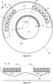
- Figures 2a and 2b illustrate a variable reluctance resolver according to another exemplifying and non-limiting embodiment.
- Figure 2a shows the variable reluctance resolver when seen along the negative z-direction of a coordinate system 299
- figure 2b shows a section taken along a geometric arc A-A shown in figure 2a .
- the variable reluctance resolver comprises a first element 201 that is a stator of the variable reluctance resolver, and a second element 204 that is a rotor of the variable reluctance resolver.
- the rotational axis of the second element 204 i.e. the rotor, is parallel with the z-axis of the coordinate system 299.
- the stator comprises a plurality of magnetic sensor sections that are placed along an arc of a geometric circle. In figures 2a and 2b , two of the magnetic sensor sections are denoted with references 202 and 203.
- the rotor comprises an air-gap surface 204 that has a periodically meandering profile with four spatial meandering periods.
- the airgap surface 205 of the rotor faces axially towards the stator and the rotor and the stator are axially successive.
- the profile of the air-gap surface 205 meanders with respect to a geometric plane 219 that is perpendicular to the z-axis of the coordinate system 299.
- a part 220 of the rotor may comprise a roll of electrically insulated ferromagnetic sheet so that the geometric axis of the roll coincides with the geometric axis of rotation of the rotor. It is also possible that the part 220 is made of e.g. ferrite or soft magnetic composite such as e.g. SOMALOY ® .
- a center part 221 of the rotor can be made of e.g. solid steel.
- First ones of the magnetic sensor sections constitute a first group 210 of equidistantly successively placed magnetic sensor sections and second ones of the magnetic sensor sections constitute a second group 211 of equidistantly successively placed magnetic sensor sections.
- the first ones of the magnetic sensor sections comprise first excitation coils and first detection coils configured to produce a first alternating output signal when alternating excitation signal is supplied to the first excitation coils.
- the second ones of the magnetic sensor sections comprise second excitation coils and second detection coils configured to produce a second alternating output signal when alternating excitation signal is supplied to the second excitation coils.
- the first group 210 of successively placed magnetic sensor sections and the second group 211 of successively placed magnetic sensor sections are mechanically arranged so that the second group 211 is displaced with respect to the first group 210 in a direction of movement of the airgap surface 205, i.e. in the circumferential direction, by C ⁇ the spatial meandering period, where C is a non-integer number.
- C 11 ⁇ 4.
- Figures 3a and 3b illustrate a variable reluctance position sensor according to an exemplifying and non-limiting embodiment.
- the variable reluctance position sensor comprises a first element 301 and a second element 304.
- the variable reluctance position sensor is a linear position sensor configured measure a position of the second element 304 with respect to the first element 301 in the x-direction of a coordinate system 399.
- Figure 3a shows the linear position sensor when seen along the negative z-direction of the coordinate system 399
- figure 3b shows a section taken along a line A-A shown in figure 3a .
- the geometric section plane is parallel with the xz-plane of the coordinate system 399.
- the first element 301 comprises a plurality of magnetic sensor sections that are placed along a geometric line.
- two of the magnetic sensor sections are denoted with references 302 and 303.
- the second element 304 comprises an air-gap surface 305 that has a periodically meandering profile with two spatial meandering periods. As shown in figure 3b , the profile of the air-gap surface 305 meanders with respect to a geometric plane 319 that is perpendicular to the z-axis of the coordinate system 399.
- First ones of the magnetic sensor sections constitute a first group 310 of equidistantly successively placed magnetic sensor sections and second ones of the magnetic sensor sections constitute a second group 311 of equidistantly successively placed magnetic sensor sections.
- the first ones of the magnetic sensor sections comprise first excitation coils and first detection coils configured to produce a first alternating output signal when alternating excitation signal is supplied to the first excitation coils.
- the second ones of the magnetic sensor sections comprise second excitation coils and second detection coils configured to produce a second alternating output signal when alternating excitation signal is supplied to the second excitation coils.
- the first group 310 of successively placed magnetic sensor sections and the second group 311 of successively placed magnetic sensor sections are mechanically arranged so that the second group 311 is displaced with respect to the first group 310 in a direction of movement of the airgap surface 305 by C ⁇ the spatial meandering period, where C is a non-integer number.
- C 11 ⁇ 4.
- FIG 4a illustrates a variable reluctance position sensor according to an exemplifying and non-limiting embodiment.
- the variable reluctance position sensor comprises a first element 401 and a second element 404.
- the variable reluctance position sensor is a variable reluctance resolver for measuring a rotational angle ⁇ of the second element 404, i.e. a rotor, with respect to the first element 401, i.e. a stator.
- the rotational axis of the second element 404 i.e. the rotor, is parallel with the z-axis of a coordinate system 499.
- the first element 401 i.e.
- the stator comprises a plurality of magnetic sensor sections that are placed along an arc of a geometric circle.
- the second element 404 i.e. the rotor, comprises an air-gap surface 405 that has a periodically meandering profile with ten spatial meandering periods, i.e. the rotor comprises ten mechanical poles.
- First ones of the magnetic sensor sections constitute a first group 410 of equidistantly successively placed magnetic sensor sections and second ones of the magnetic sensor sections constitute a second group 411 of equidistantly successively placed magnetic sensor sections.
- the first ones of the magnetic sensor sections comprise first excitation coils and first detection coils configured to produce a first alternating output signal when alternating excitation signal is supplied to the first excitation coils.
- the second ones of the magnetic sensor sections comprise second excitation coils and second detection coils configured to produce a second alternating output signal when alternating excitation signal is supplied to the second excitation coils.
- the first group 410 of successively placed magnetic sensor sections and the second group 411 of successively placed magnetic sensor sections are mechanically arranged so that the second group 411 is displaced with respect to the first group 410 in a direction of movement of the airgap surface 405, i.e. in the circumferential direction, by C ⁇ the spatial meandering period, where C is a non-integer number.
- C 11 ⁇ 4.
- the second group 411 is displaced with respect to the first group 410 by 90 electrical degrees + 360 electrical degrees i.e. by 450 electrical degrees which is 45 mechanical degrees.
- the phase-shift between the envelopes of the first and second alternating output signals is substantially 90 degrees.
- Each spatial meandering period of the airgap surface 405 represents one full period of each of the above-mentioned envelopes.
- the first element 401 comprises electrically and/or magnetically conductive elements 416 between the first and second groups 410 and 411 of successively placed magnetic sensor sections. Furthermore, the exemplifying variable reluctance resolver comprises electrically and/or magnetically conductive elements 417 at an end of the first group 410 facing away from the second group 411, and electrically and/or magnetically conductive elements 418 at an end of the second group 411 facing away from the first group 410.
- Each of the magnetic sensor sections has a magnetic core element that is separate with respect to magnetic core elements of other ones of the magnetic sensor sections.
- each of the electrically and/or magnetically conductive elements has the same shape as the magnetic core elements of magnetic sensor sections.
- the electrically and/or magnetically conductive elements can be made of e.g. aluminum, solid or laminated steel, ferrite, soft magnetic composite such as e.g. SOMALOY ® , or some other suitable electrically and/or magnetically conductive material.
- the magnetic sensor sections can be numbered for example so that the index i increases in the counterclockwise direction. In figure 4a , the index is presented with boldface numbers.
- the first detection coils are advantageously series connected.
- the first excitation coils are advantageously series connected.
- the second group 411 of successively placed magnetic sensor sections is advantageously like the first group of successively placed magnetic sensor sections.
- Figure 4b show exemplifying first and second alternating output signals 431 and 432 simulated for the variable reluctance resolver illustrated in figure 4a when the variable reluctance resolver has the following parameters and operational data: rotational speed: 1000 rpm rotor inner diameter Dri: 195 mm stator inner diameter Dsi: 242 mm axial i.e. z-directional length: 7 mm minimum air-gap length: 1.0 mm maximum air-gap length: 7.4 mm voltage of the series connection of the first and second excitation coils: 7.0 V RMS current in the first and second excitation coils: 1.5 A RMS frequency in the first and second excitation coils: 10 kHz
- the winding dimensions are the following:
- Figure 4c show an envelope 433 of the first alternating output signal 431 shown in figure 4b and an envelope 434 of the second alternating output signal 432 shown in figure 4b .
- Figure 4d shows a positioning error related to the variable reluctance position sensor illustrated in figure 4a .
- the peak-to-peak positioning error is about 0.52 electrical degrees.
- Figure 4e shows a positioning error related to a variable reluctance position sensor which is otherwise like the variable reluctance position sensor illustrated in figure 4a , but which does not comprise the electrically and/or magnetically conductive elements 416-418.
- the peak-to-peak positioning error is about 1.9 electrical degrees which is notably greater than the peak-to-peak positioning error related to the variable reluctance position sensor illustrated in figure 4a .
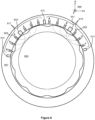
- Figure 6 illustrates a variable reluctance position sensor according to an exemplifying and non-limiting embodiment.
- the variable reluctance position sensor comprises a first element 601 and a second element 604.
- the variable reluctance position sensor is a variable reluctance resolver for measuring a rotational angle of the second element 604, i.e. a rotor, with respect to the first element 601, i.e. a stator.
- the rotational axis of the second element 604, i.e. the rotor is parallel with the z-axis of a coordinate system 699.
- the stator comprises a plurality of magnetic sensor sections that are placed along an arc of a geometric circle in a direction of the airgap surface of the rotor.
- the second element 604, i.e. the rotor comprises an air-gap surface that has a periodically meandering profile with ten spatial meandering periods, i.e. the rotor comprises ten mechanical poles.
- First ones of the magnetic sensor sections constitute a first group 610 of successively placed magnetic sensor sections and second ones of the magnetic sensor sections constitute a second group 611 of successively placed magnetic sensor sections.
- the first ones of the magnetic sensor sections comprise first excitation coils and first detection coils configured to produce a first alternating output signal when alternating excitation signal is supplied to the first excitation coils.
- the second ones of the magnetic sensor sections comprise second excitation coils and second detection coils configured to produce a second alternating output signal when alternating excitation signal is supplied to the second excitation coils.
- the first group 610 of successively placed magnetic sensor sections and the second group 611 of successively placed magnetic sensor sections are mechanically arranged so that the second group 611 is displaced with respect to the first group 610 in the direction of movement of the airgap surface, i.e. in the circumferential direction, by C ⁇ the spatial meandering period, where C is a non-integer number.
- C 21 ⁇ 4.
- the second group 611 is displaced with respect to the first group 610 by 90 electrical degrees + 720 electrical degrees i.e. by 810 electrical degrees which is 81 mechanical degrees.
- the phase-shift between the envelopes of the first and second alternating output signals is substantially 90 degrees.
- the arrangement of the magnetic sensor sections shown in figure 6 can be derived from the arrangement of the magnetic sensor sections shown in figure 4a so that the magnetic sensor sections indexed as 1, 3, and 5 in the first group 410 shown in figure 4a are shifted by one meandering period in the clockwise direction and the magnetic sensor sections indexed as 2, 4, and 6 in the second group 411 shown in figure 4a are shifted by one meandering period in the counterclockwise direction.
- the shifting is depicted with dashed line arrows in figure 6 .
- the first detection coils are advantageously series connected. In figure 6 , the index i of each magnetic sensor section is presented with a boldface number
- the first excitation coils are advantageously series connected.
- the first element 601 comprises an electrically and/or magnetically conductive element 612 between the first and second groups 610 and 611 of successively placed magnetic sensor sections. Furthermore, the first element 601 comprises electrically and/or magnetically conductive elements 613 and 614 at the other ends of the first and second groups 610 and 611. Furthermore, the first element 601 comprises an electrically and/or magnetically conductive element 641 between the middle ones of the magnetic sensor sections within the first group 610 and an electrically and/or magnetically conductive element 642 between the middle ones of the magnetic sensor sections within the second group 611.
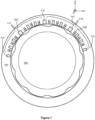
- Figure 7 illustrates a variable reluctance position sensor according to an exemplifying and non-limiting embodiment.
- the variable reluctance position sensor illustrated in figure 7 is otherwise like the variable reluctance position sensor illustrated in figure 6 , but the first element 701 comprises electrically and/or magnetically conductive elements placed between the magnetic sensor sections so that the magnetic sensor sections and the electrically and/or magnetically conductive elements are alternately in the direction of movement of the airgap surface of the first element 704.
- the first element 701 comprises electrically and/or magnetically conductive elements 713 and 714 at ends of the first and second groups 710 and 711 of magnetic sensor sections.
- three of the magnetic sensor sections that are between adjacent ones of the magnetic sensor sections are denoted with references 712, 741, and 742.
- each of the magnetic sensor sections has a magnetic core element that is separate with respect to magnetic core elements of other ones of the magnetic sensor sections.
- Each magnetic core element comprises material whose relative magnetic permeability ⁇ is greater than one. The material is advantageously ferromagnetic material.
- Each magnetic core element may comprise e.g. a stack of electrically insulated steel sheets, ferrite, or soft magnetic composite.
- each of the magnetic sensor sections has a H-shaped magnetic core element. It is also possible that each magnetic sensor section has a U-shaped magnetic core element, a C-shaped magnetic core element, an E-shaped magnetic core element, or a magnetic core element having some other suitable shape. Furthermore, it is also possible that two or more of the magnetic sensor sections have a common magnetic core that has teeth and a yoke connected to the teeth.
Landscapes
- Physics & Mathematics (AREA)
- General Physics & Mathematics (AREA)
- Engineering & Computer Science (AREA)
- Power Engineering (AREA)
- Microelectronics & Electronic Packaging (AREA)
- Condensed Matter Physics & Semiconductors (AREA)
- Transmission And Conversion Of Sensor Element Output (AREA)
Claims (15)
- Positionssensor mit variabler Reluktanz, aufweisend:- ein erstes Element (101, 201, 301, 401, 501, 601, 701), das eine Mehrzahl von magnetischen Sensorabschnitten (102, 103, 202, 203, 302, 303) aufweist, und- ein zweites Element (104, 204, 304, 404, 604, 704), das relativ zu dem ersten Element beweglich ist und eine Luftspaltoberfläche (105, 205, 305, 405) mit einem periodisch mäanderförmigen Profil mit mindestens zwei räumlichen mäandernden Perioden aufweist,wobei:- jeder der magnetischen Sensorabschnitte dazu gestaltet ist, über die Luftspaltoberfläche des zweiten Elements einen magnetischen Fluss zu und von dem zweiten Element zu leiten, und- erste der magnetischen Sensorabschnitte erste Erregerspulen (106) und erste Detektionsspulen (107), die dazu gestaltet sind, ein erstes alternierendes Ausgangssignal zu erzeugen, wenn den ersten Erregerspulen ein alternierendes Erregersignal zugeführt wird, aufweisen, und- zweite der magnetischen Sensorabschnitte zweite Erregerspulen (108) und zweite Detektionsspulen (109), die dazu gestaltet sind, ein zweites alternierendes Ausgangssignal erzeugen, wenn den zweiten Erregerspulen ein alternierendes Erregersignal zugeführt wird, aufweisen, wobei Amplituden des ersten und des zweiten alternierenden Ausgangssignals von einer Position des zweiten Elements in Bezug auf das erste Element abhängig sind, so dass Hüllkurven des ersten und des zweiten alternierenden Ausgangssignals eine Phasenverschiebung in Bezug zueinander aufweisen,dadurch gekennzeichnet, dass die ersten der magnetischen Sensorabschnitte eine erste Gruppe (110, 210, 310, 410, 510, 610, 710) nacheinander angeordneter magnetischer Sensorabschnitte bilden und die zweiten der magnetischen Sensorabschnitte eine zweite Gruppe (111, 211, 311, 411, 511, 611, 711) nacheinander angeordneter magnetischer Sensorabschnitte bilden, so dass die zweite Gruppe nacheinander angeordneter magnetischer Sensorabschnitte gegenüber der ersten Gruppe nacheinander angeordneter magnetischer Sensorabschnitte in Bewegungsrichtung der Luftspaltoberfläche um C × die räumliche Mäanderperiode versetzt (α) ist, wobei C eine nicht ganze Zahl ist.
- Positionssensor mit variabler Reluktanz nach Anspruch 1, wobei die erste Gruppe (110, 210, 310, 410) nacheinander angeordneter magnetischer Sensorabschnitte weniger als die räumliche Mäanderperiode abdeckt und die zweite Gruppe (111, 211, 311, 411) nacheinander angeordneter magnetischer Sensorabschnitte weniger als die räumliche Mäanderperiode abdeckt.
- Positionssensor mit variabler Reluktanz nach Anspruch 1 oder 2, wobei benachbarte der magnetischen Sensorabschnitte innerhalb jeder der ersten und der zweiten Gruppe (110, 210, 310, 410, 511, 111, 211, 311, 411, 511) in Bewegungsrichtung der Luftspaltoberfläche um die räumliche Mäanderperiode/N zueinander versetzt sind, wobei N die Anzahl der magnetischen Sensorabschnitte jeder der ersten und der zweiten Gruppe ist.
- Positionssensor mit variabler Reluktanz nach Anspruch 3, wobei die magnetischen Sensorabschnitte der ersten Gruppe (110, 210, 310, 410, 510) nacheinander angeordneter magnetischer Sensorabschnitte gemäß den Gleichungen gestaltet sind:

- Positionssensor mit variabler Reluktanz nach Anspruch 1, wobei benachbarte der magnetischen Sensorabschnitte innerhalb jeder der ersten und der zweiten Gruppe (610, 611) in Bewegungsrichtung der Luftspaltoberfläche um 2 × die räumliche Mäanderperiode/N relativ zueinander versetzt sind, mit der Ausnahme, dass eine Verschiebung zwischen mittleren der magnetischen Sensorabschnitte innerhalb jeder der ersten und zweite Gruppe 3 × die räumliche Mäanderperiode/N beträgt, wobei N die Anzahl der magnetischen Sensorabschnitte jeder der ersten und der zweiten Gruppe ist, so dass N = 2M ist, wobei M eine ganze Zahl ist.
- Positionssensor mit variabler Reluktanz nach Anspruch 5, wobei die magnetischen Sensorabschnitte der ersten Gruppe (610) nacheinander angeordneter magnetischer Sensorabschnitte gemäß den Gleichungen gestaltet sind:


- Positionssensor mit variabler Reluktanz nach Anspruch 4 oder 6, wobei:

- Positionssensor mit variabler Reluktanz nach Anspruch 1, wobei die zweite Gruppe (111, 211, 311, 411, 511, 611, 711) nacheinander angeordneter magnetischer Sensorabschnitte wie die erste Gruppe (110, 210, 310, 410, 510, 610, 710) nacheinander angeordneter magnetischer Sensorabschnitten ist.
- Positionssensor mit variabler Reluktanz nach einem der Ansprüche 1-8, wobei der Positionssensor mit variabler Reluktanz ein Resolver mit variabler Reluktanz ist, bei dem das erste Element (101, 201, 401) ein Stator ist und das zweite Element (104, 204, 404) ein gegenüber dem Stator drehbarer Rotor ist, wobei die magnetischen Sensorabschnitte (102, 202) der ersten Gruppe (110, 210, 410) entlang eines geometrischen Kreisbogens in Umfangsrichtung nacheinander angeordnet sind, wobei die magnetischen Sensorabschnitte (103, 203) der zweiten Gruppe (111, 211, 411) entlang des geometrischen Kreisbogens in der Umfangsrichtung nacheinander angeordnet sind, und die Position des zweiten Elements in Bezug auf das erste Element ein Drehwinkel (θ) des Rotors in Bezug auf den Stator ist.
- Positionssensor mit variabler Reluktanz nach einem der Ansprüche 1-8, wobei der Positionssensor mit variabler Reluktanz ein linearer Positionssensor mit variabler Reluktanz ist, der dazu gestaltet ist, eine Position des zweiten Elements (304) in Bezug auf das erste Element (301) in einer Richtung einer linearen Bewegung des ersten Elements in Bezug auf das zweite Element zu messen.
- Positionssensor mit variabler Reluktanz nach einem der Ansprüche 1-10, wobei jeder der magnetischen Sensorabschnitte (102, 103) ein Magnetkernelement aufweist, das in Bezug auf Magnetkernelemente anderer magnetischer Sensorabschnitte getrennt ist.
- Positionssensor mit variabler Reluktanz nach Anspruch 11, wobei das erste Element (101, 401, 501, 601, 701) eines oder mehrere elektrisch und/oder magnetisch leitende Elemente (112, 113, 416, 512, 612, 712) zwischen der ersten und zweiten Gruppe nacheinander angeordneter magnetischer Sensorabschnitte aufweist.
- Positionssensor mit variabler Reluktanz nach Anspruch 11 oder 12, wobei das erste Element (101, 401, 501, 601, 701) eines oder mehrere elektrisch und/oder magnetisch leitende Elemente (114, 417, 513, 613, 713) an einem Ende der ersten Gruppe (110, 410) nacheinander angeordneter magnetischer Sensorabschnitte, die von der zweiten Gruppe nacheinander angeordneter magnetischer Sensorabschnitte abgewandt sind, und eines oder mehrere elektrisch und/oder magnetisch leitende Elemente (115, 418, 514, 614, 714) an einem Ende der zweiten Gruppe (111, 411) nacheinander angeordneter magnetischer Sensorabschnitte, die von der ersten Gruppe nacheinander angeordneter magnetischer Sensorabschnitte abgewandt sind, aufweist.
- Positionssensor mit variabler Reluktanz nach einem der Ansprüche 11-13, wobei das erste Element (701) elektrisch und/oder magnetisch leitende Elemente (712, 741, 742) aufweist, die zwischen den magnetischen Sensorabschnitten angeordnet sind, so dass die magnetischen Sensorabschnitte und die elektrisch und/oder magnetisch leitenden Elemente in Bewegungsrichtung der Luftspaltoberfläche des ersten Elements abwechselnd liegen.
- Positionssensor mit variabler Reluktanz nach einem der Ansprüche 1-14, wobei C = 1/4 + eine ganze Zahl ist.
Applications Claiming Priority (2)
| Application Number | Priority Date | Filing Date | Title |
|---|---|---|---|
| FI20206254A FI129373B (en) | 2020-12-04 | 2020-12-04 | Variable reluctance position sensor |
| PCT/FI2021/050795 WO2022117913A1 (en) | 2020-12-04 | 2021-11-20 | A variable reluctance position sensor |
Publications (3)
| Publication Number | Publication Date |
|---|---|
| EP4256276A1 EP4256276A1 (de) | 2023-10-11 |
| EP4256276C0 EP4256276C0 (de) | 2024-10-16 |
| EP4256276B1 true EP4256276B1 (de) | 2024-10-16 |
Family
ID=78851179
Family Applications (1)
| Application Number | Title | Priority Date | Filing Date |
|---|---|---|---|
| EP21824420.0A Active EP4256276B1 (de) | 2020-12-04 | 2021-11-20 | Positionssensor mit variabler reluktanz |
Country Status (3)
| Country | Link |
|---|---|
| EP (1) | EP4256276B1 (de) |
| FI (1) | FI129373B (de) |
| WO (1) | WO2022117913A1 (de) |
Citations (3)
| Publication number | Priority date | Publication date | Assignee | Title |
|---|---|---|---|---|
| JP2000314606A (ja) * | 1999-04-30 | 2000-11-14 | Tamagawa Seiki Co Ltd | 直線位置検出装置 |
| JP2019032201A (ja) * | 2017-08-07 | 2019-02-28 | マブチモーター株式会社 | 位置センサ及びモータ |
| EP3468016A1 (de) * | 2017-10-09 | 2019-04-10 | Tyco Electronics Belgium EC bvba | Statorkern für einen winkelsensor mit variabler reluktanz |
Family Cites Families (4)
| Publication number | Priority date | Publication date | Assignee | Title |
|---|---|---|---|---|
| CN1211640C (zh) * | 2000-09-19 | 2005-07-20 | 本田技研工业株式会社 | 旋转位置探测器以及附带旋转位置探测器的马达 |
| JP5988573B2 (ja) | 2011-12-22 | 2016-09-07 | ミネベア株式会社 | Vr型レゾルバ |
| EP3324523B1 (de) * | 2016-11-22 | 2024-06-05 | Tyco Electronics Belgium EC BVBA | Variabler reluktanztypwinkelsensor mit teilweisem statorkern |
| JP7067968B2 (ja) * | 2018-03-12 | 2022-05-16 | ルネサスエレクトロニクス株式会社 | 回転角度センサシステムおよび半導体装置 |
-
2020
- 2020-12-04 FI FI20206254A patent/FI129373B/en active IP Right Grant
-
2021
- 2021-11-20 WO PCT/FI2021/050795 patent/WO2022117913A1/en not_active Ceased
- 2021-11-20 EP EP21824420.0A patent/EP4256276B1/de active Active
Patent Citations (3)
| Publication number | Priority date | Publication date | Assignee | Title |
|---|---|---|---|---|
| JP2000314606A (ja) * | 1999-04-30 | 2000-11-14 | Tamagawa Seiki Co Ltd | 直線位置検出装置 |
| JP2019032201A (ja) * | 2017-08-07 | 2019-02-28 | マブチモーター株式会社 | 位置センサ及びモータ |
| EP3468016A1 (de) * | 2017-10-09 | 2019-04-10 | Tyco Electronics Belgium EC bvba | Statorkern für einen winkelsensor mit variabler reluktanz |
Also Published As
| Publication number | Publication date |
|---|---|
| EP4256276C0 (de) | 2024-10-16 |
| FI129373B (en) | 2022-01-14 |
| EP4256276A1 (de) | 2023-10-11 |
| WO2022117913A1 (en) | 2022-06-09 |
| FI20206254A1 (en) | 2022-01-14 |
Similar Documents
| Publication | Publication Date | Title |
|---|---|---|
| JP4002308B2 (ja) | 誘導型回転位置検出装置 | |
| US20120274185A1 (en) | Motor rotor and motor | |
| CN102723185B (zh) | 一种双通道轴向磁路磁阻式旋转变压器 | |
| US8928313B2 (en) | Magnetic encoder with improved resolution | |
| CN116507884A (zh) | 用于位置传感器的检测装置和包括这种检测装置的检测系统 | |
| US10655987B2 (en) | Resolver | |
| CN114977712B (zh) | 可变磁阻型旋转变压器 | |
| JP5151958B2 (ja) | 位置検出装置およびそれを備えた回転直動モータ | |
| US10677613B2 (en) | Resolver | |
| EP4256276B1 (de) | Positionssensor mit variabler reluktanz | |
| US20220021278A1 (en) | Integrated encoder and resolver | |
| JP2011047672A (ja) | シートコイル型レゾルバ | |
| EP4158280B1 (de) | Positionssensor mit variabler reluktanz | |
| CN219351458U (zh) | 一种电主轴用电机 | |
| CN114864271B (zh) | 一种旋转变压器的线圈绕制方法 | |
| CN115276361B (zh) | 一种磁阻式旋转变压器的绕线方法 | |
| JP5135277B2 (ja) | 回転型位置検出装置 | |
| US20260025049A1 (en) | Variable reluctance resolver | |
| CN116131537B (zh) | 一种电主轴用电机 | |
| JP2008029070A (ja) | 角度検出器 | |
| JP3044061B2 (ja) | 位置検出装置 | |
| CN121399432A (zh) | 仅布置在一个角扇形上的感应式角位置传感器 | |
| KR101891929B1 (ko) | 레졸버 | |
| JPH076709U (ja) | 可変リラクタンス型レゾルバ | |
| JP2014169899A (ja) | 位置センサ |
Legal Events
| Date | Code | Title | Description |
|---|---|---|---|
| STAA | Information on the status of an ep patent application or granted ep patent |
Free format text: STATUS: UNKNOWN |
|
| STAA | Information on the status of an ep patent application or granted ep patent |
Free format text: STATUS: THE INTERNATIONAL PUBLICATION HAS BEEN MADE |
|
| PUAI | Public reference made under article 153(3) epc to a published international application that has entered the european phase |
Free format text: ORIGINAL CODE: 0009012 |
|
| STAA | Information on the status of an ep patent application or granted ep patent |
Free format text: STATUS: REQUEST FOR EXAMINATION WAS MADE |
|
| 17P | Request for examination filed |
Effective date: 20230516 |
|
| AK | Designated contracting states |
Kind code of ref document: A1 Designated state(s): AL AT BE BG CH CY CZ DE DK EE ES FI FR GB GR HR HU IE IS IT LI LT LU LV MC MK MT NL NO PL PT RO RS SE SI SK SM TR |
|
| DAV | Request for validation of the european patent (deleted) | ||
| DAX | Request for extension of the european patent (deleted) | ||
| GRAP | Despatch of communication of intention to grant a patent |
Free format text: ORIGINAL CODE: EPIDOSNIGR1 |
|
| STAA | Information on the status of an ep patent application or granted ep patent |
Free format text: STATUS: GRANT OF PATENT IS INTENDED |
|
| INTG | Intention to grant announced |
Effective date: 20240621 |
|
| GRAS | Grant fee paid |
Free format text: ORIGINAL CODE: EPIDOSNIGR3 |
|
| GRAA | (expected) grant |
Free format text: ORIGINAL CODE: 0009210 |
|
| STAA | Information on the status of an ep patent application or granted ep patent |
Free format text: STATUS: THE PATENT HAS BEEN GRANTED |
|
| AK | Designated contracting states |
Kind code of ref document: B1 Designated state(s): AL AT BE BG CH CY CZ DE DK EE ES FI FR GB GR HR HU IE IS IT LI LT LU LV MC MK MT NL NO PL PT RO RS SE SI SK SM TR |
|
| REG | Reference to a national code |
Ref country code: GB Ref legal event code: FG4D |
|
| REG | Reference to a national code |
Ref country code: DE Ref legal event code: R096 Ref document number: 602021020461 Country of ref document: DE Ref country code: CH Ref legal event code: EP |
|
| REG | Reference to a national code |
Ref country code: IE Ref legal event code: FG4D |
|
| U01 | Request for unitary effect filed |
Effective date: 20241101 |
|
| U07 | Unitary effect registered |
Designated state(s): AT BE BG DE DK EE FI FR IT LT LU LV MT NL PT RO SE SI Effective date: 20241113 |
|
| U20 | Renewal fee for the european patent with unitary effect paid |
Year of fee payment: 4 Effective date: 20250128 |
|
| PG25 | Lapsed in a contracting state [announced via postgrant information from national office to epo] |
Ref country code: HR Free format text: LAPSE BECAUSE OF FAILURE TO SUBMIT A TRANSLATION OF THE DESCRIPTION OR TO PAY THE FEE WITHIN THE PRESCRIBED TIME-LIMIT Effective date: 20241016 Ref country code: IS Free format text: LAPSE BECAUSE OF FAILURE TO SUBMIT A TRANSLATION OF THE DESCRIPTION OR TO PAY THE FEE WITHIN THE PRESCRIBED TIME-LIMIT Effective date: 20250216 |
|
| PG25 | Lapsed in a contracting state [announced via postgrant information from national office to epo] |
Ref country code: ES Free format text: LAPSE BECAUSE OF FAILURE TO SUBMIT A TRANSLATION OF THE DESCRIPTION OR TO PAY THE FEE WITHIN THE PRESCRIBED TIME-LIMIT Effective date: 20241016 |
|
| PG25 | Lapsed in a contracting state [announced via postgrant information from national office to epo] |
Ref country code: NO Free format text: LAPSE BECAUSE OF FAILURE TO SUBMIT A TRANSLATION OF THE DESCRIPTION OR TO PAY THE FEE WITHIN THE PRESCRIBED TIME-LIMIT Effective date: 20250116 |
|
| PG25 | Lapsed in a contracting state [announced via postgrant information from national office to epo] |
Ref country code: GR Free format text: LAPSE BECAUSE OF FAILURE TO SUBMIT A TRANSLATION OF THE DESCRIPTION OR TO PAY THE FEE WITHIN THE PRESCRIBED TIME-LIMIT Effective date: 20250117 |
|
| PG25 | Lapsed in a contracting state [announced via postgrant information from national office to epo] |
Ref country code: PL Free format text: LAPSE BECAUSE OF FAILURE TO SUBMIT A TRANSLATION OF THE DESCRIPTION OR TO PAY THE FEE WITHIN THE PRESCRIBED TIME-LIMIT Effective date: 20241016 |
|
| PG25 | Lapsed in a contracting state [announced via postgrant information from national office to epo] |
Ref country code: RS Free format text: LAPSE BECAUSE OF FAILURE TO SUBMIT A TRANSLATION OF THE DESCRIPTION OR TO PAY THE FEE WITHIN THE PRESCRIBED TIME-LIMIT Effective date: 20250116 |
|
| REG | Reference to a national code |
Ref country code: CH Ref legal event code: PL |
|
| PG25 | Lapsed in a contracting state [announced via postgrant information from national office to epo] |
Ref country code: SM Free format text: LAPSE BECAUSE OF FAILURE TO SUBMIT A TRANSLATION OF THE DESCRIPTION OR TO PAY THE FEE WITHIN THE PRESCRIBED TIME-LIMIT Effective date: 20241016 |
|
| PG25 | Lapsed in a contracting state [announced via postgrant information from national office to epo] |
Ref country code: MC Free format text: LAPSE BECAUSE OF FAILURE TO SUBMIT A TRANSLATION OF THE DESCRIPTION OR TO PAY THE FEE WITHIN THE PRESCRIBED TIME-LIMIT Effective date: 20241016 |
|
| REG | Reference to a national code |
Ref country code: CH Ref legal event code: PL |
|
| PG25 | Lapsed in a contracting state [announced via postgrant information from national office to epo] |
Ref country code: CH Free format text: LAPSE BECAUSE OF NON-PAYMENT OF DUE FEES Effective date: 20241130 |
|
| PG25 | Lapsed in a contracting state [announced via postgrant information from national office to epo] |
Ref country code: SK Free format text: LAPSE BECAUSE OF FAILURE TO SUBMIT A TRANSLATION OF THE DESCRIPTION OR TO PAY THE FEE WITHIN THE PRESCRIBED TIME-LIMIT Effective date: 20241016 |
|
| PG25 | Lapsed in a contracting state [announced via postgrant information from national office to epo] |
Ref country code: CZ Free format text: LAPSE BECAUSE OF FAILURE TO SUBMIT A TRANSLATION OF THE DESCRIPTION OR TO PAY THE FEE WITHIN THE PRESCRIBED TIME-LIMIT Effective date: 20241016 |
|
| PLBE | No opposition filed within time limit |
Free format text: ORIGINAL CODE: 0009261 |
|
| STAA | Information on the status of an ep patent application or granted ep patent |
Free format text: STATUS: NO OPPOSITION FILED WITHIN TIME LIMIT |
|
| 26N | No opposition filed |
Effective date: 20250717 |
|
| PG25 | Lapsed in a contracting state [announced via postgrant information from national office to epo] |
Ref country code: IE Free format text: LAPSE BECAUSE OF NON-PAYMENT OF DUE FEES Effective date: 20241120 |
|
| U20 | Renewal fee for the european patent with unitary effect paid |
Year of fee payment: 5 Effective date: 20251127 |
|
| PG25 | Lapsed in a contracting state [announced via postgrant information from national office to epo] |
Ref country code: HU Free format text: LAPSE BECAUSE OF FAILURE TO SUBMIT A TRANSLATION OF THE DESCRIPTION OR TO PAY THE FEE WITHIN THE PRESCRIBED TIME-LIMIT; INVALID AB INITIO Effective date: 20211120 |