EP4254451A1 - Ampoule à vide - Google Patents
Ampoule à vide Download PDFInfo
- Publication number
- EP4254451A1 EP4254451A1 EP22165701.8A EP22165701A EP4254451A1 EP 4254451 A1 EP4254451 A1 EP 4254451A1 EP 22165701 A EP22165701 A EP 22165701A EP 4254451 A1 EP4254451 A1 EP 4254451A1
- Authority
- EP
- European Patent Office
- Prior art keywords
- contact piece
- region
- layer
- powdered material
- mould
- Prior art date
- Legal status (The legal status is an assumption and is not a legal conclusion. Google has not performed a legal analysis and makes no representation as to the accuracy of the status listed.)
- Pending
Links
- 239000000463 material Substances 0.000 claims description 109
- 239000012254 powdered material Substances 0.000 claims description 106
- 239000011800 void material Substances 0.000 claims description 33
- 238000000034 method Methods 0.000 claims description 22
- 229910000831 Steel Inorganic materials 0.000 claims description 18
- 229910001220 stainless steel Inorganic materials 0.000 claims description 18
- 239000010935 stainless steel Substances 0.000 claims description 18
- 239000010959 steel Substances 0.000 claims description 18
- 229910015269 MoCu Inorganic materials 0.000 claims description 17
- 238000003466 welding Methods 0.000 claims description 16
- 238000004519 manufacturing process Methods 0.000 claims description 15
- 238000002844 melting Methods 0.000 claims description 13
- 230000008018 melting Effects 0.000 claims description 13
- 238000003825 pressing Methods 0.000 claims description 11
- 238000005245 sintering Methods 0.000 claims description 10
- 229910052804 chromium Inorganic materials 0.000 description 42
- 229910052782 aluminium Inorganic materials 0.000 description 37
- 229910052735 hafnium Inorganic materials 0.000 description 37
- 229910052742 iron Inorganic materials 0.000 description 37
- 229910052758 niobium Inorganic materials 0.000 description 37
- 229910052710 silicon Inorganic materials 0.000 description 37
- 229910052715 tantalum Inorganic materials 0.000 description 37
- 229910052718 tin Inorganic materials 0.000 description 37
- 229910052720 vanadium Inorganic materials 0.000 description 37
- 229910052726 zirconium Inorganic materials 0.000 description 37
- 239000000654 additive Substances 0.000 description 34
- 230000000996 additive effect Effects 0.000 description 27
- 239000010949 copper Substances 0.000 description 27
- 239000000843 powder Substances 0.000 description 19
- 150000004767 nitrides Chemical class 0.000 description 10
- 229910052802 copper Inorganic materials 0.000 description 9
- RYGMFSIKBFXOCR-UHFFFAOYSA-N Copper Chemical compound [Cu] RYGMFSIKBFXOCR-UHFFFAOYSA-N 0.000 description 4
- 239000000203 mixture Substances 0.000 description 4
- 229910052750 molybdenum Inorganic materials 0.000 description 4
- 229910052709 silver Inorganic materials 0.000 description 4
- 229910052721 tungsten Inorganic materials 0.000 description 4
- 230000001419 dependent effect Effects 0.000 description 2
- 239000011651 chromium Substances 0.000 description 1
- 238000012938 design process Methods 0.000 description 1
- 230000005484 gravity Effects 0.000 description 1
- 239000011261 inert gas Substances 0.000 description 1
- 230000008595 infiltration Effects 0.000 description 1
- 238000001764 infiltration Methods 0.000 description 1
- 239000012212 insulator Substances 0.000 description 1
- 238000002360 preparation method Methods 0.000 description 1
- 239000011819 refractory material Substances 0.000 description 1
- 230000002787 reinforcement Effects 0.000 description 1
- 239000007787 solid Substances 0.000 description 1
- 238000007711 solidification Methods 0.000 description 1
- 230000008023 solidification Effects 0.000 description 1
Images


Classifications
-
- H—ELECTRICITY
- H01—ELECTRIC ELEMENTS
- H01H—ELECTRIC SWITCHES; RELAYS; SELECTORS; EMERGENCY PROTECTIVE DEVICES
- H01H33/00—High-tension or heavy-current switches with arc-extinguishing or arc-preventing means
- H01H33/60—Switches wherein the means for extinguishing or preventing the arc do not include separate means for obtaining or increasing flow of arc-extinguishing fluid
- H01H33/66—Vacuum switches
- H01H33/6606—Terminal arrangements
-
- B—PERFORMING OPERATIONS; TRANSPORTING
- B22—CASTING; POWDER METALLURGY
- B22F—WORKING METALLIC POWDER; MANUFACTURE OF ARTICLES FROM METALLIC POWDER; MAKING METALLIC POWDER; APPARATUS OR DEVICES SPECIALLY ADAPTED FOR METALLIC POWDER
- B22F3/00—Manufacture of workpieces or articles from metallic powder characterised by the manner of compacting or sintering; Apparatus specially adapted therefor ; Presses and furnaces
- B22F3/004—Filling molds with powder
-
- B—PERFORMING OPERATIONS; TRANSPORTING
- B22—CASTING; POWDER METALLURGY
- B22F—WORKING METALLIC POWDER; MANUFACTURE OF ARTICLES FROM METALLIC POWDER; MAKING METALLIC POWDER; APPARATUS OR DEVICES SPECIALLY ADAPTED FOR METALLIC POWDER
- B22F7/00—Manufacture of composite layers, workpieces, or articles, comprising metallic powder, by sintering the powder, with or without compacting wherein at least one part is obtained by sintering or compression
- B22F7/06—Manufacture of composite layers, workpieces, or articles, comprising metallic powder, by sintering the powder, with or without compacting wherein at least one part is obtained by sintering or compression of composite workpieces or articles from parts, e.g. to form tipped tools
-
- C—CHEMISTRY; METALLURGY
- C22—METALLURGY; FERROUS OR NON-FERROUS ALLOYS; TREATMENT OF ALLOYS OR NON-FERROUS METALS
- C22C—ALLOYS
- C22C1/00—Making non-ferrous alloys
- C22C1/04—Making non-ferrous alloys by powder metallurgy
- C22C1/045—Alloys based on refractory metals
-
- C—CHEMISTRY; METALLURGY
- C22—METALLURGY; FERROUS OR NON-FERROUS ALLOYS; TREATMENT OF ALLOYS OR NON-FERROUS METALS
- C22C—ALLOYS
- C22C1/00—Making non-ferrous alloys
- C22C1/10—Alloys containing non-metals
-
- C—CHEMISTRY; METALLURGY
- C22—METALLURGY; FERROUS OR NON-FERROUS ALLOYS; TREATMENT OF ALLOYS OR NON-FERROUS METALS
- C22C—ALLOYS
- C22C29/00—Alloys based on carbides, oxides, nitrides, borides, or silicides, e.g. cermets, or other metal compounds, e.g. oxynitrides, sulfides
- C22C29/02—Alloys based on carbides, oxides, nitrides, borides, or silicides, e.g. cermets, or other metal compounds, e.g. oxynitrides, sulfides based on carbides or carbonitrides
- C22C29/06—Alloys based on carbides, oxides, nitrides, borides, or silicides, e.g. cermets, or other metal compounds, e.g. oxynitrides, sulfides based on carbides or carbonitrides based on carbides, but not containing other metal compounds
- C22C29/08—Alloys based on carbides, oxides, nitrides, borides, or silicides, e.g. cermets, or other metal compounds, e.g. oxynitrides, sulfides based on carbides or carbonitrides based on carbides, but not containing other metal compounds based on tungsten carbide
-
- C—CHEMISTRY; METALLURGY
- C22—METALLURGY; FERROUS OR NON-FERROUS ALLOYS; TREATMENT OF ALLOYS OR NON-FERROUS METALS
- C22C—ALLOYS
- C22C32/00—Non-ferrous alloys containing at least 5% by weight but less than 50% by weight of oxides, carbides, borides, nitrides, silicides or other metal compounds, e.g. oxynitrides, sulfides, whether added as such or formed in situ
- C22C32/0005—Non-ferrous alloys containing at least 5% by weight but less than 50% by weight of oxides, carbides, borides, nitrides, silicides or other metal compounds, e.g. oxynitrides, sulfides, whether added as such or formed in situ with at least one oxide and at least one of carbides, nitrides, borides or silicides as the main non-metallic constituents
-
- H—ELECTRICITY
- H01—ELECTRIC ELEMENTS
- H01H—ELECTRIC SWITCHES; RELAYS; SELECTORS; EMERGENCY PROTECTIVE DEVICES
- H01H1/00—Contacts
- H01H1/02—Contacts characterised by the material thereof
- H01H1/0203—Contacts characterised by the material thereof specially adapted for vacuum switches
- H01H1/0206—Contacts characterised by the material thereof specially adapted for vacuum switches containing as major components Cu and Cr
-
- H—ELECTRICITY
- H01—ELECTRIC ELEMENTS
- H01H—ELECTRIC SWITCHES; RELAYS; SELECTORS; EMERGENCY PROTECTIVE DEVICES
- H01H1/00—Contacts
- H01H1/02—Contacts characterised by the material thereof
- H01H1/021—Composite material
- H01H1/025—Composite material having copper as the basic material
-
- H—ELECTRICITY
- H01—ELECTRIC ELEMENTS
- H01H—ELECTRIC SWITCHES; RELAYS; SELECTORS; EMERGENCY PROTECTIVE DEVICES
- H01H11/00—Apparatus or processes specially adapted for the manufacture of electric switches
- H01H11/04—Apparatus or processes specially adapted for the manufacture of electric switches of switch contacts
- H01H11/048—Apparatus or processes specially adapted for the manufacture of electric switches of switch contacts by powder-metallurgical processes
-
- H—ELECTRICITY
- H01—ELECTRIC ELEMENTS
- H01H—ELECTRIC SWITCHES; RELAYS; SELECTORS; EMERGENCY PROTECTIVE DEVICES
- H01H33/00—High-tension or heavy-current switches with arc-extinguishing or arc-preventing means
- H01H33/60—Switches wherein the means for extinguishing or preventing the arc do not include separate means for obtaining or increasing flow of arc-extinguishing fluid
- H01H33/66—Vacuum switches
- H01H33/664—Contacts; Arc-extinguishing means, e.g. arcing rings
-
- B—PERFORMING OPERATIONS; TRANSPORTING
- B22—CASTING; POWDER METALLURGY
- B22F—WORKING METALLIC POWDER; MANUFACTURE OF ARTICLES FROM METALLIC POWDER; MAKING METALLIC POWDER; APPARATUS OR DEVICES SPECIALLY ADAPTED FOR METALLIC POWDER
- B22F2998/00—Supplementary information concerning processes or compositions relating to powder metallurgy
- B22F2998/10—Processes characterised by the sequence of their steps
-
- B—PERFORMING OPERATIONS; TRANSPORTING
- B22—CASTING; POWDER METALLURGY
- B22F—WORKING METALLIC POWDER; MANUFACTURE OF ARTICLES FROM METALLIC POWDER; MAKING METALLIC POWDER; APPARATUS OR DEVICES SPECIALLY ADAPTED FOR METALLIC POWDER
- B22F2999/00—Aspects linked to processes or compositions used in powder metallurgy
-
- C—CHEMISTRY; METALLURGY
- C22—METALLURGY; FERROUS OR NON-FERROUS ALLOYS; TREATMENT OF ALLOYS OR NON-FERROUS METALS
- C22C—ALLOYS
- C22C1/00—Making non-ferrous alloys
- C22C1/04—Making non-ferrous alloys by powder metallurgy
- C22C1/05—Mixtures of metal powder with non-metallic powder
- C22C1/059—Making alloys comprising less than 5% by weight of dispersed reinforcing phases
-
- H—ELECTRICITY
- H01—ELECTRIC ELEMENTS
- H01H—ELECTRIC SWITCHES; RELAYS; SELECTORS; EMERGENCY PROTECTIVE DEVICES
- H01H1/00—Contacts
- H01H1/02—Contacts characterised by the material thereof
- H01H1/0203—Contacts characterised by the material thereof specially adapted for vacuum switches
Definitions
- the present invention relates to a vacuum interrupter and a method of manufacturing a contact piece for a vacuum interrupter.
- Vacuum interrupters have contact terminals, usually made of copper, that carry contact pieces that are in the inside of the vacuum chamber.
- the contact pieces have the task of closing and opening electrical circuits; they have to withstand the energy of the vacuum arc, they have to limit contact welding, they have to provide a low ohmic resistance and they have to be economic in production.
- contact pieces usually consist of a mixture of two main materials, one main material is a refractory material with a high melting temperature, like Cr, Mo, W or WC, for obtaining a high durability regarding melting and welding, and the second main material for obtaining a low ohmic resistance, like Cu or Ag.
- VI contact pieces may contain certain additives for improving the durability.
- VI contact pieces For mechanical reasons, for steering the direction of current flow and magnetic field generation, and for a certain thermal capacity, VI contact pieces have a certain thickness, that is in the range of about 10 mm, while the area that is really exposed to the vacuum arc and where reinforcement against melting and welding is required, is only a few mm thick.
- the material of the contact pieces is relatively expensive for its durability against melting and welding.
- the mentioned mixtures of for example Cu, Cr and additives can comprise complex, energy intensive and costly manufacturing processes, compared to for example a contact piece made of pure copper. Pure copper however cannot withstand the vacuum arc to the required degree.
- a vacuum interrupter comprising:
- the fixed contact piece is connected to the fixed terminal.
- the movable contact piece is connected to the movable terminal.
- the fixed contact piece comprises a first layer or region and a second layer or region.
- the movable contact piece comprises a first layer or region and a second layer or region.
- the vacuum interrupter In a deactivated state the vacuum interrupter is configured to hold the fixed contact piece spaced from the movable contact piece. In an activated state the vacuum interrupter is configured to move the movable terminal to bring the first layer or region of the movable contact piece into contact with the first layer or region of the fixed contact piece.
- the first layer or region of the fixed contact piece is configured to be arc resistant.
- the first layer or region of the movable contact piece is configured to be arc resistant.
- the first layer or region of the fixed contact piece comprises at least two materials.
- a first material of the at least two materials of the fixed contact piece has a low ohmic resistance and a second material of the at least two materials of the fixed contact piece has a high durability against melting and welding.
- the first layer or region of the movable contact piece comprises at least two materials.
- a first material of the at least two materials of the movable contact piece has a low ohmic resistance and a second material of the at least two materials of the movable contact piece has a high durability against melting and welding.
- the first layer or region of the fixed contact piece comprises: CuCr, MoCu, WCu, or WCAg.
- the first layer or region of the movable contact piece comprises: CuCr, MoCu, WCu, or WCAg.
- the second layer or region of the fixed contact piece is configured to support the first layer or region of the fixed contact piece.
- the second layer or region of the movable contact piece is configured to support the first layer or region of the movable contact piece.
- the second layer or region of the fixed contact piece comprises Cu and/or Ag and/or Stainless steel and/or steel.
- the second layer or region of the movable contact piece comprises Cu and/or Ag and/or Stainless steel and/or steel.
- a method of manufacturing a contact piece for a vacuum interrupter comprising:
- the method comprises pressing the first powdered material with a stamp.
- the stamp used to press the first powdered material is different to the stamp used to press the first powdered material and the second powdered material.
- filling the void above the movable base of the part of the mould with the first powdered material comprises sliding a slider over the part of the mould, and a base portion of the slider slides at the first set level.
- filling the void above the movable base of the part of the mould with the first powdered material comprises transferring the first powdered material from the slider to the part of the mould.
- filling the void above the first powdered material in the part of the mould with the second powdered material comprises sliding a slider over the part of the mould, and a base portion of the slider slides at the second set level.
- filling the void above the first powdered material in the part of the mould with the second powdered material comprises transferring the second powdered material material from the slider to the part of the mould.
- the method before sintering the pressed first powdered material and second powdered material the method comprises removing the pressed first powdered material and second powdered material from the mould.
- removing the pressed first powdered material and second powdered material from the mould comprises moving the movable base toward the first set level of the mould.
- Figs 1-12 relate to a vacuum interrupter having new types of contact piece and a method of manufacturing a new type of contact piece for a vacuum interrupter.
- the vacuum interrupter 1 comprises a fixed terminal 40, a fixed contact piece 50, a movable terminal 70, and a movable contact piece 60.
- the fixed contact piece is connected to the fixed terminal.
- the movable contact piece is connected to the movable terminal.
- the fixed contact piece comprises a first layer or region 52 and a second layer or region 54.
- the movable contact piece comprises a first layer or region 62 and a second layer or region 64.
- a deactivated state the vacuum interrupter is configured to hold the fixed contact piece spaced from the movable contact piece.
- an activated state the vacuum interrupter is configured to move the movable terminal to bring the first layer or region of the movable contact piece into contact with the first layer or region of the fixed contact piece.
- the first layer or region of the fixed contact piece is configured to be arc resistant.
- the first layer or region of the movable contact piece is configured to be arc resistant.
- the first layer or region of the fixed contact piece comprises at least two materials.
- a first material of the at least two materials of the fixed contact piece has a low ohmic resistance and a second material of the at least two materials of the fixed contact piece has a high durability against melting and welding.
- the first layer or region of the movable contact piece comprises at least two materials.
- a first material of the at least two materials of the movable contact piece has a low ohmic resistance and a second material of the at least two materials of the movable contact piece has a high durability against melting and welding.
- the first layer or region of the fixed contact piece comprises one or more of: Cr, Mo, W, WC.
- the first layer or region of the movable contact piece comprises one or more of: Cr, Mo, W, WC.
- the first layer or region of the fixed contact piece comprises: CuCr, MoCu, WCu, WCCu or WCAg.
- the first layer or region of the movable contact piece comprises: CuCr, MoCu, WCu, WCCu or WCAg.
- the first layer or region of the fixed contact piece comprises endowed CuCr.
- this is "Pure" CuCr with a few % of an additive.
- the first layer or region of the fixed contact piece comprises endowed MoCu.
- this is "Pure" MoCu with a few % of an additive.
- the first layer or region of the fixed contact piece comprises endowed WCu.
- this is "pure” WCu with a few % of an additive.
- the first layer or region of the fixed contact piece comprises endowed WCCu.
- this is "pure" WCCu with a few % of an additive.
- the first layer or region of the fixed contact piece comprises endowed WCAg.
- this is "pure" WCAg with a few % of an additive.
- the first layer or region of the fixed contact piece comprises CuCr with a content of 0.1% to 5% of at least one material comprising Fe, Al, Cr, V, Nb, Ta, Hf, Sn, Zr or Si.
- the first layer or region of the fixed contact piece comprises MoCu with a content of 0.1% to 5% of at least one material comprising Fe, Al, Cr, V, Nb, Ta, Hf, Sn, Zr or Si.
- the first layer or region of the fixed contact piece comprises WCu with a content of 0.1% to 5% of at least one material comprising Fe, Al, Cr, V, Nb, Ta, Hf, Sn, Zr or Si.
- the first layer or region of the fixed contact piece comprises WCCu with a content of 0.1% to 5% of at least one material comprising Fe, Al, Cr, V, Nb, Ta, Hf, Sn, Zr or Si.
- the first layer or region of the fixed contact piece comprises WCAg with a content of 0.1% to 5% of at least one material comprising Fe, Al, Cr, V, Nb, Ta, Hf, Sn, Zr or Si.
- the at least one material comprises an oxide, nitride or boride of Fe, Al, Cr, V, Nb, Ta, Hf, Sn, Zr or Si.
- the first layer or region of the fixed contact piece comprises a relatively pure material or a composition of two relatively pure main components, alloyed with additives like oxides, nitrides or borides of Fe, Al, Cr, V, Nb, Ta, Hf, Sn, Zr or Si with a relative content of about 0.1% to 5% acting as dispersoids for increasing the hardness and the welding resistance.
- the first layer or region of the movable contact piece comprises endowed CuCr.
- this is "Pure" CuCr with a few % of an additive.
- the first layer or region of the movable contact piece comprises endowed MoCu.
- this is "Pure" MoCu with a few % of an additive.
- the first layer or region of the movable contact piece comprises endowed WCu.
- this is "pure” WCu with a few % of an additive.
- the first layer or region of the movable contact piece comprises endowed WCCu.
- this is "pure" WCCu with a few % of an additive.
- the first layer or region of the movable contact piece comprises endowed WCAg.
- this is "pure" WCAg with a few % of an additive.
- the first layer or region of the movable contact piece comprises CuCr with a content of 0.1% to 5% of at least one material comprising Fe, Al, Cr, V, Nb, Ta, Hf, Sn, Zr or Si.
- the first layer or region of the movable contact piece comprises MoCu with a content of 0.1% to 5% of at least one material comprising Fe, Al, Cr, V, Nb, Ta, Hf, Sn, Zr or Si.
- the first layer or region of the movable contact piece comprises WCu with a content of 0.1% to 5% of at least one material comprising Fe, Al, Cr, V, Nb, Ta, Hf, Sn, Zr or Si.
- the first layer or region of the movable contact piece comprises WCCu with a content of 0.1% to 5% of at least one material comprising Fe, Al, Cr, V, Nb, Ta, Hf, Sn, Zr or Si.
- the first layer or region of the movable contact piece comprises WCAg with a content of 0.1% to 5% of at least one material comprising Fe, Al, Cr, V, Nb, Ta, Hf, Sn, Zr or Si.
- the at least one material comprises an oxide, nitride or boride of Fe, Al, Cr, V, Nb, Ta, Hf, Sn, Zr or Si.
- the first layer or region of the movable contact piece comprises a relatively pure material alloyed with additives like oxides, nitrides or borides of Fe, Al, Cr, V, Nb, Ta, Hf, Sn, Zr or Si with a relative content of about 0.1% to 5% acting as dispersoids for increasing the hardness and the welding resistance.
- the second layer or region of the fixed contact piece is configured to support the first layer or region of the fixed contact piece.
- the second layer or region of the movable contact piece is configured to support the first layer or region of the movable contact piece.
- the second layer or region of the fixed contact piece comprises Cu and/or Ag and/or Stainless steel and/or steel.
- the second layer or region of the movable contact piece comprises Cu and/or Ag and/or Stainless steel and/or steel.
- the second layer or region of the fixed contact piece comprises endowed Cu.
- this is "Pure” Cu with a few % of an additive.
- the second layer or region of the fixed contact piece comprises endowed Ag.
- this is "Pure” Ag with a few % of an additive.
- the second layer or region of the fixed contact piece comprises endowed steel.
- this is Steel with a few % of an additive.
- the second layer or region of the fixed contact piece comprises endowed stainless steel.
- this is stainless steel with a few % of an additive.
- the second layer or region of the fixed contact piece comprises Cu with a content of 0.1% to 5% of at least one material comprising Fe, Al, Cr, V, Nb, Ta, Hf, Sn, Zr or Si.
- the second layer or region of the fixed contact piece comprises Ag with a content of 0.1% to 5% of at least one material comprising Fe, Al, Cr, V, Nb, Ta, Hf, Sn, Zr or Si.
- the second layer or region of the fixed contact piece comprises steel with a content of 0.1% to 5% of at least one material comprising Fe, Al, Cr, V, Nb, Ta, Hf, Sn, Zr or Si.
- the second layer or region of the fixed contact piece comprises Stainless steel with a content of 0.1% to 5% of at least one material comprising Fe, Al, Cr, V, Nb, Ta, Hf, Sn, Zr or Si.
- the at least one material comprises an oxide, nitride or boride of Fe, Al, Cr, V, Nb, Ta, Hf, Sn, Zr or Si.
- the second layer or region of the fixed contact piece comprises a relatively pure material alloyed with additives like oxides, nitrides or borides of Fe, Al, Cr, V, Nb, Ta, Hf, Sn, Zr or Si with a relative content of about 0.1% to 5% acting as dispersoids for increasing the hardness and the welding resistance.
- the second layer or region of the movable contact piece comprises endowed Cu.
- this is "Pure” Cu with a few % of an additive.
- the second layer or region of the movable contact piece comprises endowed Ag.
- this is "Pure” Ag with a few % of an additive.
- the second layer or region of the movable contact piece comprises endowed steel.
- this is Steel with a few % of an additive.
- the second layer or region of the movable contact piece comprises endowed stainless steel.
- this is stainless steel with a few % of an additive.
- the second layer or region of the movable contact piece comprises Cu with a content of 0.1% to 5% of at least one material comprising Fe, Al, Cr, V, Nb, Ta, Hf, Sn, Zr or Si.
- the second layer or region of the movable contact piece comprises Ag with a content of 0.1% to 5% of at least one material comprising Fe, Al, Cr, V, Nb, Ta, Hf, Sn, Zr or Si.
- the second layer or region of the movable contact piece comprises steel with a content of 0.1% to 5% of at least one material comprising Fe, Al, Cr, V, Nb, Ta, Hf, Sn, Zr or Si.
- the second layer or region of the movable contact piece comprises Stainless steel with a content of 0.1% to 5% of at least one material comprising Fe, Al, Cr, V, Nb, Ta, Hf, Sn, Zr or Si.
- the at least one material comprises an oxide, nitride or boride of Fe, Al, Cr, V, Nb, Ta, Hf, Sn, Zr or Si.
- the second layer or region of the movable contact piece comprises a relatively pure material alloyed with additives like oxides, nitrides or borides of Fe, Al, Cr, V, Nb, Ta, Hf, Sn, Zr or Si with a relative content of about 0.1% to 5% acting as dispersoids for increasing the hardness and the welding resistance.
- the method of manufacturing a contact piece 50, 60 for a vacuum interrupter comprises a first layer or region 52, 62 and a second layer or region 54, 64.
- the first layer or region of the contact piece is configured to be arc resistant.
- the second layer or region of the contact piece is configured to support the first layer or region of the contact piece.
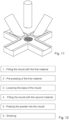
- the method comprises:
- the method comprises pressing the first powdered material with a stamp.
- the stamp used to press the first powdered material is the same as the stamp used to press the first powdered material and the second powdered material.
- the stamp used to press the first powdered material is different to the stamp used to press the first powdered material and the second powdered material.
- filling the void above the movable base of the part of the mould with the first powdered material comprises sliding a slider 130 over the part of the mould. A base portion of the slider slides at the first set level.
- filling the void above the movable base of the part of the mould with the first powdered material comprises transferring the first powdered material material from the slider to the part of the mould.
- filling the void above the first powdered material in the part of the mould with the second powdered material comprises sliding a slider 140 over the part of the mould. A base portion of the slider slides at the second set level.
- filling the void above the first powdered material in the part of the mould with the second powdered material comprises transferring the second powdered material material from the slider to the part of the mould.
- the first set level is defined by an upper surface of the mould.
- the first set level defined by the upper surface of the mould is an upper surface of the mould upon which the slider used in filling the part of the mould with the first powdered material slides.
- the second set level is defined by an upper surface of the mould.
- the second set level defined by the upper surface of the mould is an upper surface of the mould upon which the slider used in filling the part of the mould with the second powdered material slides.
- the first set level is the same as the second set level.
- the slider used in filling the part of the mould with the first powdered material is different to the slider used in filling the part of the mould with the second powdered material.
- the slider used in filling the part of the mould with the first powdered material is the same as the slider used in filling the part of the mould with the second powdered material.
- the method before sintering the pressed first powdered material and second powdered material the method comprises removing the pressed first powdered material and second powdered material from the mould.
- removing the pressed first powdered material and second powdered material from the mould comprises moving the movable base toward the first set level of the mould.
- the pressed and sintered first powdered material forms the first layer or region of the contact piece
- the pressed and sintered second powdered material forms the second layer or region of the contact piece
- the pressed and sintered first powdered material forms the second layer or region of the contact piece
- the pressed and sintered second powdered material forms the first layer or region of the contact piece
- the first layer or region of the contact piece comprises at least two materials, wherein a first material of the at least two materials of the contact piece has a low ohmic resistance and a second material of the at least two materials of the contact piece has a high durability against melting and welding.
- the first layer or region of the contact piece comprises one or more of: Cr, Mo, W, WC.
- the first layer or region of the contact piece comprises: CuCr, MoCu, WCu, WCCu or WCAg.
- the first layer or region of the contact piece comprises endowed CuCr.
- this is "Pure" CuCr with a few % of an additive.
- the first layer or region of the contact piece comprises endowed MoCu.
- this is "Pure" MoCu with a few % of an additive.
- the first layer or region of the contact piece comprises endowed WCu.
- this is "Pure" WCu with a few % of an additive.
- the first layer or region of the contact piece comprises endowed WCCu.
- this is "Pure" WCCu with a few % of an additive.
- the first layer or region of the contact piece comprises endowed WCAg.
- this is "Pure" WCAg with a few % of an additive.
- the first layer or region of the contact piece comprises CuCr with a content of 0.1% to 5% of at least one material comprising Fe, Al, Cr, V, Nb, Ta, Hf, Sn, Zr or Si.
- the first layer or region of the contact piece comprises MoCu with a content of 0.1% to 5% of at least one material comprising Fe, Al, Cr, V, Nb, Ta, Hf, Sn, Zr or Si.
- the first layer or region of the contact piece comprises WCu with a content of 0.1% to 5% of at least one material comprising Fe, Al, Cr, V, Nb, Ta, Hf, Sn, Zr or Si.
- the first layer or region of the contact piece comprises WCCu with a content of 0.1% to 5% of at least one material comprising Fe, Al, Cr, V, Nb, Ta, Hf, Sn, Zr or Si.
- the first layer or region of the contact piece comprises WCAg with a content of 0.1% to 5% of at least one material comprising Fe, Al, Cr, V, Nb, Ta, Hf, Sn, Zr or Si.
- the at least one material comprises an oxide, nitride or boride of Fe, Al, Cr, V, Nb, Ta, Hf, Sn, Zr or Si.
- the second layer or region of the contact piece comprises Cu and/or Ag and/or Stainless steel and/or steel.
- the second layer or region of the contact piece comprises endowed Cu.
- this is "Pure” Cu with a few % of an additive.
- the second layer or region of the contact piece comprises endowed Ag.
- this is "Pure” Ag with a few % of an additive.
- the second layer or region of the contact piece comprises endowed steel.
- this is Steel with a few % of an additive.
- the second layer or region of the contact piece comprises endowed stainless steel.
- this is stainless steel with a few % of an additive.
- the second layer or region of the contact piece comprises Cu with a content of 0.1% to 5% of at least one material comprising Fe, Al, Cr, V, Nb, Ta, Hf, Sn, Zr or Si.
- the second layer or region of the contact piece comprises Ag with a content of 0.1% to 5% of at least one material comprising Fe, Al, Cr, V, Nb, Ta, Hf, Sn, Zr or Si.
- the second layer or region of the contact piece comprises steel with a content of 0.1% to 5% of at least one material comprising Fe, Al, Cr, V, Nb, Ta, Hf, Sn, Zr or Si.
- the second layer or region of the contact piece comprises Stainless steel with a content of 0.1% to 5% of at least one material comprising Fe, Al, Cr, V, Nb, Ta, Hf, Sn, Zr or Si.
- the at least one material comprises an oxide, nitride or boride of Fe, Al, Cr, V, Nb, Ta, Hf, Sn, Zr or Si.
- Fig. 1 shows a sectional view of a vacuum interrupter with two-layer contact pieces; some details of the vacuum interrupter, like shields, have been omitted for clarity.
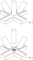
- the movable base 120 of the mould was positioned in a way that the sliding movement forth and back of the first slider 130 with the first powder 132 will fill the void between the vertically movable base 120 and the table 110, as shown in Figs. 2-4 .
- the table 110 can be considered to be a mould.
- the movable base 120 is located at a part of the mould.
- the powder 132 that is contained in the slider 130 will fall into the void by gravity.
- a contact piece with a cylindrical shape can be prepared in the mould, and one or more features of the completed contact piece, like slits 56, chamfers 57, cylindrical cut-outs 58, 59 or the like can directly be realised in the pressing process if they are required.
- the pressed contact piece can be a basic shape, a net shape or near net shape.
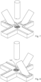
- the first slider 130 has a base portion that sits on and slides on a surface of the mould 110 and as it is moved back and forth it creates a flat top to the powder 132 that fills what was a void above the movable base 120.
- the surface of the mould upon which the first slider slides defines a first set level.
- Stamp 150 is pressed into the powder (see Fig. 5 and Fig. 6 ) for a first solidification of the first material, forming the first layer of the contact piece.
- the pressure of the stamp can be reduced compared to the full pressure that would be applied in step 5 for the final preparation of the sintering process, as the bond between the two layers after the sintering process can be reduced when the first material is already fully pressed before the second material was added. For the same reason, this step 2 can be optionally omitted.
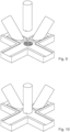
- Step 3 Lowering the base of the mould.
- This step provides the space for the second powder 142 (see Fig. 7 ).
- the lowering of the base 120 of the mould can as well be supported by the stamp 150 to ensure that the fist layer of the contact piece is completely following the base 120, so that the correct void for the second material is created.
- a sliding movement forth and back of the second slider 140 with the second powder 142 will fill the void between the first powder 132 and the table 110, as shown in Figs. 8-9 .
- the second slider 140 has a base portion that sits on and slides on a surface of the mould 110 and as it is moved back and forth it creates a flat top to the powder 142 that fills what was a void above first powder 132 on the movable base 120.
- the surface of the mould upon which the second slider slides defines a second set level.
- first and second sliders do not need to contain the first and second powders, but can be used just to form the flat top of the first powder and second powder respectively, with the powders being transferred into the voids by some other means. Indeed, there can be only one slider.
- the stamp 150 In this step, all the powder in the mould will be compressed with the stamp 150 (See Fig. 10 ).
- the stamp can now have a different shape compared to the stamp for the first pressing (step 2) to enable the features that are required for the corresponding side of the contact piece, e.g. the cylindrical cut-out 58 for assembly to the corresponding terminal.
- the contact piece When the stamp 150 is withdrawn (See Fig. 11 ), the contact piece can be removed from the mould. This removal can be supported by an upward motion of the base 120.
- the contact piece is now a solid block having the desired shape and the desired two-layer structure.
- the sintering of the pressed contact piece is carried out in a state of the art process, for example at a temperature below the melting temperature of copper, or a little bit above this temperature to obtain infiltration, and under an inert gas or in vacuum.
- the first material is a dedicated vacuum interrupter contact piece material, for example CuCr, MoCu, WCAg, WCu or the like, with various material shares for example CuCr10, CuCr25, CuCr35, and CuCr50. It may further contain additives or dispersoids to increase the durability against melting and welding. These materials can require a relatively complex, energy intensive and costly manufacturing processes. However, in the new contact piece design and manufacturing process they are being used only where they are required, i.e. in that first region of the contact piece that is directly exposed to the vacuum arc.
- the remaining second region of the contact piece can be filled with a relatively inexpensive material, for example pure Cu or even Ag, which has the main tasks to transfer the current with low losses, to steer the direction of the current inside the contact pieces for the generation of the desired magnetic field, like TMF or AMF, to mechanically support the first region, and to transfer excessive heat from the first region of the contact piece to the terminals of the vacuum interrupter.
- a relatively inexpensive material for example pure Cu or even Ag
- An additional advantage of using pure Cu or Ag for this second region is that this pure material has a better electrical and thermal conductivity compared to the dedicated vacuum interrupter contact piece material of the first region of the contact piece, so that also the overall losses of a contact piece are reduced compared to the state of the art, i.e. a contact piece entirely made of the material used in the first region.
- This filling material can for example be steel or stainless steel.
- the ohmic resistance of such a mixture will be higher than of e.g. pure Cu, but using pure Cu for the second material would already be an improvement compared to the state of the art, where e.g. CuCr would be used for the entire contact piece.
- the current path in the region of the second material is not long when the entire vacuum interrupter is considered, so this aspect can be omitted for many applications.
- the other main tasks of the second material i.e. the mechanical support and the thermal capacity, are not affected by using this filling material.
- the advantages of using a combination of powders of Cu or Ag with a filling material like powders of steel of stainless steel as the second material are the material costs and the fact that the coefficients of thermal expansion of the second material and the first material, for example CuCr, are much closer compared to for example pure Cu as the second material. This improves the bond between the two layers of the contact piece after the entire production process.
- the second material can be filled first into the mould, followed by the first material so that the direction of the contact in the press can be chosen.
- a vacuum interrupter having both a fixed contact piece and a movable contact piece of the new two layer design.
- a vacuum interrupter can have one contact piece of the new design and one standard contact piece.
- the new fixed contact piece and the new movable contact piece in a vacuum interrupter, of a vacuum interrupter can be of different diameter and/or thickness.
Landscapes
- Chemical & Material Sciences (AREA)
- Engineering & Computer Science (AREA)
- Mechanical Engineering (AREA)
- Materials Engineering (AREA)
- Metallurgy (AREA)
- Organic Chemistry (AREA)
- Manufacturing & Machinery (AREA)
- Composite Materials (AREA)
- Contacts (AREA)
Priority Applications (2)
| Application Number | Priority Date | Filing Date | Title |
|---|---|---|---|
| EP22165701.8A EP4254451A1 (fr) | 2022-03-30 | 2022-03-30 | Ampoule à vide |
| CN202310299075.3A CN116895491A (zh) | 2022-03-30 | 2023-03-24 | 真空断续器 |
Applications Claiming Priority (1)
| Application Number | Priority Date | Filing Date | Title |
|---|---|---|---|
| EP22165701.8A EP4254451A1 (fr) | 2022-03-30 | 2022-03-30 | Ampoule à vide |
Publications (1)
| Publication Number | Publication Date |
|---|---|
| EP4254451A1 true EP4254451A1 (fr) | 2023-10-04 |
Family
ID=81074048
Family Applications (1)
| Application Number | Title | Priority Date | Filing Date |
|---|---|---|---|
| EP22165701.8A Pending EP4254451A1 (fr) | 2022-03-30 | 2022-03-30 | Ampoule à vide |
Country Status (2)
| Country | Link |
|---|---|
| EP (1) | EP4254451A1 (fr) |
| CN (1) | CN116895491A (fr) |
Citations (5)
| Publication number | Priority date | Publication date | Assignee | Title |
|---|---|---|---|---|
| JPS4937807A (fr) * | 1972-08-11 | 1974-04-08 | ||
| WO2006079495A1 (fr) * | 2005-01-27 | 2006-08-03 | Abb Technology Ag | Procede de fabrication d'un element de contact et element de contact destine a une chambre de commutation a vide |
| EP2081200A2 (fr) * | 2008-01-21 | 2009-07-22 | Hitachi, Ltd. | Contact électrique pour soupape sous vide |
| DE202005021749U1 (de) * | 2005-04-16 | 2009-10-01 | Abb Technology Ag | Kontaktstück für Vakuumschaltkammern |
| DE102014006371A1 (de) * | 2014-05-05 | 2015-11-05 | Gkn Sinter Metals Engineering Gmbh | Wasserstoffspeicher-Herstellvorrichtung nebst Verfahren hierzu und Wasserstoffspeicher |
-
2022
- 2022-03-30 EP EP22165701.8A patent/EP4254451A1/fr active Pending
-
2023
- 2023-03-24 CN CN202310299075.3A patent/CN116895491A/zh active Pending
Patent Citations (5)
| Publication number | Priority date | Publication date | Assignee | Title |
|---|---|---|---|---|
| JPS4937807A (fr) * | 1972-08-11 | 1974-04-08 | ||
| WO2006079495A1 (fr) * | 2005-01-27 | 2006-08-03 | Abb Technology Ag | Procede de fabrication d'un element de contact et element de contact destine a une chambre de commutation a vide |
| DE202005021749U1 (de) * | 2005-04-16 | 2009-10-01 | Abb Technology Ag | Kontaktstück für Vakuumschaltkammern |
| EP2081200A2 (fr) * | 2008-01-21 | 2009-07-22 | Hitachi, Ltd. | Contact électrique pour soupape sous vide |
| DE102014006371A1 (de) * | 2014-05-05 | 2015-11-05 | Gkn Sinter Metals Engineering Gmbh | Wasserstoffspeicher-Herstellvorrichtung nebst Verfahren hierzu und Wasserstoffspeicher |
Also Published As
| Publication number | Publication date |
|---|---|
| CN116895491A (zh) | 2023-10-17 |
Similar Documents
| Publication | Publication Date | Title |
|---|---|---|
| US7704449B2 (en) | Electrode, electrical contact and method of manufacturing the same | |
| US4325734A (en) | Method and apparatus for forming compact bodies from conductive and non-conductive powders | |
| US5557083A (en) | Vacuum circuit breaker and electric contact | |
| TWI449072B (zh) | Electrical contacts for vacuum valves | |
| US4190753A (en) | High-density high-conductivity electrical contact material for vacuum interrupters and method of manufacture | |
| US6048216A (en) | Vacuum circuit breaker as well as vacuum valve and electric contact used in same | |
| US20020144977A1 (en) | Electrode of a vacuum valve, a producing method thereof, a vacuum valve, a vacuum circuit-breaker and a contact point of the electrode | |
| US9368301B2 (en) | Vacuum interrupter with arc-resistant center shield | |
| JP2005135778A (ja) | 電気接点とその製造法及び真空バルブ用電極とそれを用いた真空バルブ並びに真空遮断器 | |
| US10008341B2 (en) | Monolithic contact system and method of forming | |
| US3828428A (en) | Matrix-type electrodes having braze-penetration barrier | |
| EP4254451A1 (fr) | Ampoule à vide | |
| US10629397B2 (en) | Contact member, method for producing the same, and vacuum interrupter | |
| US5697150A (en) | Method forming an electric contact in a vacuum circuit breaker | |
| JP2001135206A (ja) | 電極及び真空バルブ用電極と真空バルブ並びに真空開閉器 | |
| US3548135A (en) | Contacts for vacuum interrupters | |
| US4513186A (en) | Vacuum interrupter contact structure and method of fabrication | |
| JP4855836B2 (ja) | 真空バルブの接点と通電軸の製造方法 | |
| JP2006120373A (ja) | 真空遮断器,真空バルブ及び電極とその製法 | |
| JP2001307602A (ja) | 真空バルブ用接点材料およびその製造方法 | |
| JP5159947B2 (ja) | 真空バルブ用電気接点およびそれを用いた真空遮断器 | |
| JP2002373537A (ja) | 真空遮断器用電極とその製造方法及び真空バルブ並びに真空遮断器 | |
| JPH09312120A (ja) | 真空バルブ用接点材料 | |
| JP3443516B2 (ja) | 真空バルブ用接点材料の製造方法 | |
| JPH09161583A (ja) | 真空遮断器用接点部材の製造方法 |
Legal Events
| Date | Code | Title | Description |
|---|---|---|---|
| PUAI | Public reference made under article 153(3) epc to a published international application that has entered the european phase |
Free format text: ORIGINAL CODE: 0009012 |
|
| STAA | Information on the status of an ep patent application or granted ep patent |
Free format text: STATUS: THE APPLICATION HAS BEEN PUBLISHED |
|
| AK | Designated contracting states |
Kind code of ref document: A1 Designated state(s): AL AT BE BG CH CY CZ DE DK EE ES FI FR GB GR HR HU IE IS IT LI LT LU LV MC MK MT NL NO PL PT RO RS SE SI SK SM TR |
|
| STAA | Information on the status of an ep patent application or granted ep patent |
Free format text: STATUS: REQUEST FOR EXAMINATION WAS MADE |
|
| 17P | Request for examination filed |
Effective date: 20240228 |
|
| RBV | Designated contracting states (corrected) |
Designated state(s): AL AT BE BG CH CY CZ DE DK EE ES FI FR GB GR HR HU IE IS IT LI LT LU LV MC MK MT NL NO PL PT RO RS SE SI SK SM TR |