EP4254381B1 - Travel control method and travel control device - Google Patents
Travel control method and travel control device Download PDFInfo
- Publication number
- EP4254381B1 EP4254381B1 EP20963401.3A EP20963401A EP4254381B1 EP 4254381 B1 EP4254381 B1 EP 4254381B1 EP 20963401 A EP20963401 A EP 20963401A EP 4254381 B1 EP4254381 B1 EP 4254381B1
- Authority
- EP
- European Patent Office
- Prior art keywords
- prescribed
- vehicle
- boundary lines
- host vehicle
- lane boundary
- Prior art date
- Legal status (The legal status is an assumption and is not a legal conclusion. Google has not performed a legal analysis and makes no representation as to the accuracy of the status listed.)
- Active
Links
Images


Classifications
-
- B—PERFORMING OPERATIONS; TRANSPORTING
- B60—VEHICLES IN GENERAL
- B60W—CONJOINT CONTROL OF VEHICLE SUB-UNITS OF DIFFERENT TYPE OR DIFFERENT FUNCTION; CONTROL SYSTEMS SPECIALLY ADAPTED FOR HYBRID VEHICLES; ROAD VEHICLE DRIVE CONTROL SYSTEMS FOR PURPOSES NOT RELATED TO THE CONTROL OF A PARTICULAR SUB-UNIT
- B60W30/00—Purposes of road vehicle drive control systems not related to the control of a particular sub-unit, e.g. of systems using conjoint control of vehicle sub-units
- B60W30/18—Propelling the vehicle
- B60W30/18009—Propelling the vehicle related to particular drive situations
- B60W30/18159—Traversing an intersection
-
- B—PERFORMING OPERATIONS; TRANSPORTING
- B60—VEHICLES IN GENERAL
- B60W—CONJOINT CONTROL OF VEHICLE SUB-UNITS OF DIFFERENT TYPE OR DIFFERENT FUNCTION; CONTROL SYSTEMS SPECIALLY ADAPTED FOR HYBRID VEHICLES; ROAD VEHICLE DRIVE CONTROL SYSTEMS FOR PURPOSES NOT RELATED TO THE CONTROL OF A PARTICULAR SUB-UNIT
- B60W30/00—Purposes of road vehicle drive control systems not related to the control of a particular sub-unit, e.g. of systems using conjoint control of vehicle sub-units
- B60W30/10—Path keeping
- B60W30/12—Lane keeping
-
- B—PERFORMING OPERATIONS; TRANSPORTING
- B60—VEHICLES IN GENERAL
- B60W—CONJOINT CONTROL OF VEHICLE SUB-UNITS OF DIFFERENT TYPE OR DIFFERENT FUNCTION; CONTROL SYSTEMS SPECIALLY ADAPTED FOR HYBRID VEHICLES; ROAD VEHICLE DRIVE CONTROL SYSTEMS FOR PURPOSES NOT RELATED TO THE CONTROL OF A PARTICULAR SUB-UNIT
- B60W60/00—Drive control systems specially adapted for autonomous road vehicles
- B60W60/001—Planning or execution of driving tasks
-
- G—PHYSICS
- G06—COMPUTING OR CALCULATING; COUNTING
- G06V—IMAGE OR VIDEO RECOGNITION OR UNDERSTANDING
- G06V20/00—Scenes; Scene-specific elements
- G06V20/50—Context or environment of the image
- G06V20/56—Context or environment of the image exterior to a vehicle by using sensors mounted on the vehicle
- G06V20/588—Recognition of the road, e.g. of lane markings; Recognition of the vehicle driving pattern in relation to the road
-
- G—PHYSICS
- G08—SIGNALLING
- G08G—TRAFFIC CONTROL SYSTEMS
- G08G1/00—Traffic control systems for road vehicles
- G08G1/16—Anti-collision systems
- G08G1/167—Driving aids for lane monitoring, lane changing, e.g. blind spot detection
-
- B—PERFORMING OPERATIONS; TRANSPORTING
- B60—VEHICLES IN GENERAL
- B60W—CONJOINT CONTROL OF VEHICLE SUB-UNITS OF DIFFERENT TYPE OR DIFFERENT FUNCTION; CONTROL SYSTEMS SPECIALLY ADAPTED FOR HYBRID VEHICLES; ROAD VEHICLE DRIVE CONTROL SYSTEMS FOR PURPOSES NOT RELATED TO THE CONTROL OF A PARTICULAR SUB-UNIT
- B60W2540/00—Input parameters relating to occupants
- B60W2540/20—Direction indicator values
-
- B—PERFORMING OPERATIONS; TRANSPORTING
- B60—VEHICLES IN GENERAL
- B60W—CONJOINT CONTROL OF VEHICLE SUB-UNITS OF DIFFERENT TYPE OR DIFFERENT FUNCTION; CONTROL SYSTEMS SPECIALLY ADAPTED FOR HYBRID VEHICLES; ROAD VEHICLE DRIVE CONTROL SYSTEMS FOR PURPOSES NOT RELATED TO THE CONTROL OF A PARTICULAR SUB-UNIT
- B60W2552/00—Input parameters relating to infrastructure
- B60W2552/53—Road markings, e.g. lane marker or crosswalk
-
- B—PERFORMING OPERATIONS; TRANSPORTING
- B60—VEHICLES IN GENERAL
- B60W—CONJOINT CONTROL OF VEHICLE SUB-UNITS OF DIFFERENT TYPE OR DIFFERENT FUNCTION; CONTROL SYSTEMS SPECIALLY ADAPTED FOR HYBRID VEHICLES; ROAD VEHICLE DRIVE CONTROL SYSTEMS FOR PURPOSES NOT RELATED TO THE CONTROL OF A PARTICULAR SUB-UNIT
- B60W2556/00—Input parameters relating to data
- B60W2556/10—Historical data
Definitions
- the present invention relates to a travel control method and a travel control device.
- Patent Document 1 discloses a road shape detection method for the accurate identification of the shape of a lane by combining vehicle travel information during autonomous driving with vehicle travel information during manual driving.
- This road shape detection method identifies the detected point (travel locus) of the current position of a vehicle over time during autonomous driving as the lane center line and identifies the lane boundaries based on the distribution of the distance between the identified lane center line and the detected points of the current position over time during manual driving.
- Patent Document 2 discloses a travel control method for a vehicle equipped with a controller that detects lane boundary lines provided at widthwise ends of a host vehicle lane in which a host vehicle is traveling and that carries out a travel control of the host vehicle based on a detection result of the lane boundary lines.
- Patent Document 3 discloses a method for controlling a travelling vehicle which travels through an intersection. Virtual while lines of the traveling route that the vehicle is to travel after passing through the intersection are extended in a direction opposite to the vehicle travelling direction.
- an object of the present invention is to provide a travel control method and a travel control device with which it is possible for a vehicle to travel in a prescribed position within its own lane, even in sections where lane boundary lines cannot be detected.
- the travel control method detects lane boundary lines provided at the widthwise ends of the vehicle lane in which a host vehicle is traveling and carries out travel control of the host vehicle based on the detection result of the lane boundary lines.
- a first prescribed position with respect to the lane boundary lines is calculated and stored when the vehicle goes from a state in which the lane boundary lines can be detected to a state in which the lane boundary lines cannot be detected, and a second prescribed position with respect to the lane boundary lines is calculated and stored when the vehicle goes from a state in which the lane boundary lines cannot be detected to a state in which the lane boundary lines can be detected.
- the host vehicle is then controlled to travel along a travel path connecting the first prescribed position and the second prescribed position during travel in a section for which the first and second prescribed positions are stored.
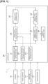
- the travel control device 1 comprises a camera 10, a speed sensor 11, an angular velocity sensor 12, a GNSS receiver 13, and a controller 20.
- the travel control device 1 according to this embodiment is mounted in a vehicle V and controls the travel of vehicle V.
- the travel control device 1 may be mounted in a vehicle that has an autonomous driving function or a vehicle that does not have an autonomous driving function.
- the travel control device 1 may also be mounted in a vehicle capable of switching between autonomous driving and manual driving.
- Autonomous driving in this embodiment refers to a state in which, for example, at least one actuator, such as the brake, accelerator, steering, is controlled without any operation from the occupant. Therefore, other actuators may be operated by an operation from the occupant.
- Autonomous driving may also be any state in which any control, such as acceleration/deceleration control, lateral position control, etc., is being executed.
- manual driving in this embodiment refers to a state in which the occupant is operating the brake, accelerator, or steering wheel, for example.
- the camera 10 is mounted on vehicle V and photographs the surroundings of vehicle V.
- the camera 10 comprises an imaging element, such as a CCD (charge-coupled device), CMOS (complementary metal oxide semiconductor), and the like.
- the camera 10 sequentially outputs the captured images to the controller 20.
- the speed sensor 11 detects the travel speed (vehicle speed) of vehicle V.
- the speed sensor 11 includes, for example, a sensor rotor that rotates together with a wheel and that has a protrusion (gear pulser) formed on the circumference thereof and a detection circuit having a pickup coil provided to face the protrusion of the sensor rotor.
- the speed sensor 11 converts the change in the magnetic flux density accompanying the rotation of the sensor rotor into a voltage signal by means of the pickup coil and measures the wheel speed of each wheel from the voltage signal.
- the speed sensor 11 computes the average wheel speed of each wheel as the vehicle speed.
- the speed sensor 11 outputs the detected vehicle speed of vehicle V to the controller 20.
- the angular velocity sensor 12 detects angular velocity of vehicle V and outputs the detected angular velocity to the controller 20.
- the GNSS receiver 13 is a GPS receiver or the like, which detects the position of vehicle V on the ground (hereafter may be referred to as self-location) by receiving radio waves from a plurality of satellites.
- the GNSS receiver 13 outputs the detected position information of vehicle V to the controller 20.
- GNSS is an acronym for "Global Navigation Satellite System”
- GPS Global Positioning System
- the controller 20 is a general-purpose microcomputer with a CPU (central processing device), memory, and an input/output unit.
- a computer program is installed in the microcomputer to make it function as the travel control device 1.
- the microcomputer functions as a plurality of information processing circuits provided in the travel control device 1.
- the plurality of information processing circuits provided in the travel control device 1 are realized in software in the example shown here, it is of course possible to configure the plurality of information processing circuits as dedicated hardware, in order to execute each of the following information processes.
- the plurality of information processing circuits may also be realized in discrete hardware.
- the controller 20 includes the following as the plurality of information processing circuits: a lane boundary line detection unit 21, a relative position estimation unit 22, an absolute position estimation unit 23, a travel path calculation unit 24, a travel path storage unit 25, a travel path retrieval unit 26, a travel path correction unit 27, and a vehicle control unit 28.
- the lane boundary line detection unit 21 detects lane boundary lines ahead of the vehicle, which are provided at the widthwise ends of the host vehicle lane in which vehicle V is traveling.
- Lane boundary lines are division lines that delineate a roadway, such as the white lines on the road surface, raised pavement markers, or curbs.
- the lane boundary line detection unit 21 detects the relative positions of vehicle V and the detected lane boundary line.
- the relative position detected by the lane boundary line detection unit 21 is a position in a vehicle coordinate system.
- the vehicle coordinate system may be set, for example, such that the center of the rear axle of vehicle V is the origin, the forward direction is the positive direction of the x axis, and the left direction is the positive direction of the y axis.
- a formula for converting from the coordinate system of the camera 10 to the coordinate system of the vehicle is set in advance in the lane boundary line detection unit 21.
- the relative position estimation unit 22 acquires the vehicle speed of vehicle V from the speed sensor 11 and the angular velocity of vehicle V from the angular velocity sensor 12.
- the relative position estimation unit 22 estimates the relative position and attitude (azimuth angle) of vehicle V in a relative coordinate system with a certain position as the origin by so-called odometry, in which the distance and direction of movement of the vehicle V is calculated from the acquired vehicle speed and angular velocity. For example, when the travel control device 1 is activated or when the process is reset, the relative position and the relative azimuth angle of vehicle V are estimated with the position of vehicle V as the origin and the azimuth angle of vehicle V set to 0°.
- the relative position estimation unit 22 may estimate the relative position and the relative azimuth angle of vehicle V by odometry using the steering angle and rpm of the wheels, or estimate the relative position and relative azimuth angle of vehicle V by odometry using the steering and rotation speed of the wheels.
- the parameters used for odometry are not particularly limited.
- the absolute position estimation unit 23 acquires the self-location of vehicle V from the GNSS receiver 13, the vehicle speed of vehicle V from the speed sensor 11, and the angular velocity of vehicle V from the angular velocity sensor 12.
- the absolute position estimation unit 23 estimates the absolute position of the vehicle V from the acquired self-location, vehicle speed, and angular velocity of vehicle V using a Kalman filter.
- the self-location acquired from the GNSS receiver 13 contains errors due to the presence of obstacles, etc. By combining the self-location acquired from the GNSS receiver 13 with the vehicle speed and angular velocity, the absolute position estimation unit 23 can suppress the effect of errors in the self-location.
- the travel path calculation unit 24 calculates and stores a prescribed position relative to a lane boundary line detected by vehicle V at a first point as the first prescribed position. A prescribed position relative to a lane boundary line detected at a second point after vehicle V has traveled for a prescribed interval from the first point is then calculated and stored as the second prescribed position.
- the travel path calculation unit 24 calculates and stores, for example, the center positions of the lane boundary lines detected at the first and second points as the first and second prescribed positions. For example, the travel path calculation unit 24 calculates and stores the first and second prescribed positions during manual driving travel of vehicle V.
- the travel path calculation unit 24 calculates and stores the direction along the host vehicle lane at the first prescribed position and the direction along the host vehicle lane at the second prescribed position.
- the travel path calculation unit 24 checks the operating state of the turn indicator of vehicle V while vehicle V travels in the section from the first prescribed position to the second prescribed position. In the case that the turn indicator of vehicle V is not activated while vehicle V travels in the section from the first prescribed position to the second prescribed position, the travel path calculation unit 24 calculates a travel path connecting the stored first and second prescribed positions. The travel path calculation unit 24 calculates a travel path that connects the first and second prescribed positions such that the orientation thereof matches the direction along the host vehicle lane at the first prescribed position and/or the direction along the host vehicle lane at the second prescribed position.
- the travel path calculation unit 24 determines whether a deviation of a prescribed value or more exists between the azimuth angles of vehicle V at the first and second points or between the first and second prescribed positions. If a deviation of a prescribed value or more exists between the azimuth angles of vehicle V at the first and second points or between the first and second prescribed positions, a travel path connecting the first and second prescribed positions is then calculated. If a deviation of the prescribed value or more does not exist between the azimuth angles of vehicle V at the first and second points or between the first and second prescribed positions, a travel path is not calculated. Details of the travel path calculation method of the travel path calculation unit 24 will be described further below with reference to Figures 2-4 .
- the travel path storage unit 25 stores in memory in the controller 20, as a set, the absolute position and the absolute azimuth angle of vehicle V at the first point, the positions of the lane boundary lines detected by vehicle V at the first point, and the first and second prescribed positions and the travel paths calculated by the travel path calculation unit 24.
- the travel path retrieval unit 26 retrieves the travel path closest to the current absolute position of vehicle V within a prescribed range from the current absolute position of vehicle V from the travel paths stored in the travel path storage unit 25. For example, during autonomous driving travel of the vehicle V, the travel path retrieval unit 26 retrieves the travel path closest to the current absolute position of vehicle V within a prescribed range from the current absolute position of the vehicle V from the travel paths stored in the travel path storage unit 25. Details of the travel path retrieval method of the travel path retrieval unit 26 will be described further below with reference to Figure 5 .
- the travel path correction unit 27 corrects the travel path retrieved by the travel path retrieval unit 26. Based on the difference between the respective positions of the lane boundary lines stored as a set with the travel path retrieved by the travel path retrieval unit 26 and the positions of the lane boundary lines detected by the current vehicle V, the travel path correction unit 27 corrects the travel path retrieved by the travel path retrieval unit 26 to a relative travel path with respect to the current vehicle V. The corrected travel path is then set as the travel path of the current vehicle V. Details of the travel path correction method of the travel path correction unit 27 will be described further below with reference to Figure 5 .
- the vehicle control unit 28 controls the actuators of vehicle V such that vehicle V follows the travel path corrected by the travel path correction unit 27.
- the actuators include brake actuators, accelerator pedal actuators, steering actuators, etc.
- Figure 2 shows a scenario in which vehicle V passes through an intersection during manual driving travel.
- the travel path calculation unit 24 acquires the positions of lane boundary lines 41a, 42a detected by vehicle V in front of the intersection (first point).
- the travel path calculation unit 24 calculates the center position of the lane boundary lines 41a, 42a and stores this position as a first prescribed position P1. Since lane boundary lines are not present within the intersection shown in Figure 2 , when vehicle V enters the intersection, vehicle V cannot detect lane boundary lines while traveling along a travel locus 51a. When vehicle V then passes through the intersection, vehicle V will again be able to detect lane boundary lines.
- the travel path calculation unit 24 acquires the positions of lane boundary lines 43a, 44a detected at the point (second point) at which vehicle V has passed through the intersection.
- the center position of the lane boundary lines 43a, 44a is then calculated and stored as a second prescribed position P2.
- the travel path calculation unit 24 calculates and stores a direction D1 along the host vehicle lane at first prescribed position P1 and a direction D2 along the host vehicle lane at second prescribed position P2.
- the travel path calculation unit 24 determines that the turn indicator of vehicle V has not been activated as vehicle V travels in the section from first prescribed position P1 to second prescribed position P2.
- a travel path 61a that connects first prescribed position P1 and second prescribed position P2 is then calculated such that its orientation matches direction D1 along the host vehicle lane at first prescribed position P1 and/or the direction along the host vehicle lane at second prescribed position P2.
- the travel path storage unit 25 stores in memory in the controller 20 the absolute position A1 and the azimuth angle of vehicle V at the first point, the positions of the lane boundary lines 41a, 42a, first and second prescribed positions P1, P2, and the travel path 61 a as a set.
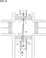
- Figure 3 shows a scenario in which vehicle V makes a right turn at an intersection during manual driving travel.
- the travel path calculation unit 24 acquires the positions of lane boundary lines 41b, 42b detected by vehicle V in front of the intersection (first point).
- the travel path calculation unit 24 calculates the center position of the lane boundary lines 41b, 42b and stores this position as a first prescribed position P1.
- vehicle V cannot detect lane boundary lines while traveling along a travel locus 51b to turn right at the intersection.
- vehicle V then turns right at the intersection, vehicle V will again be able to detect lane boundary lines.
- the travel path calculation unit 24 acquires the positions of lane boundary lines 43b, 44b detected at the point (second point) at which vehicle V passed through the intersection.
- the center position of the lane boundary lines 43b, 44b is then calculated and stored as a second prescribed position P2.
- the travel path calculation unit 24 calculates and stores a direction D1 along the host vehicle lane at the first prescribed position and a direction D2 along the host vehicle lane at the second prescribed position.
- the travel path calculation unit 24 determines that the turn indicator of vehicle V has been activated as vehicle V travels in the section from first prescribed position P1 to second prescribed position P2. The travel path calculation unit 24 then determines that a deviation of a prescribed value or more exists between the azimuth angles of vehicle V at the first and second points or between the first and second prescribed positions P1, P2. A smooth curve that connects first and second prescribed positions P1, P2, such that its orientation matches direction D1 along the host vehicle lane at first prescribed position P1 and/or direction D2 along the host vehicle lane at second prescribed position P2, is then calculated as a travel path 61b. The travel path calculation unit 24 calculates the travel path 61b using a clothoid curve or a spline curve, for example.
- the travel path storage unit 25 stores in memory in the controller 20 the absolute position A1 and azimuth angle of vehicle V at the first point, the positions of the lane boundary lines 41b, 42b, first and second prescribed positions P1, P2, and the travel path 61b as a set.
- Figure 4 shows a scenario in which vehicle V changes lanes during manual driving travel.
- the travel path calculation unit 24 acquires the positions of lane boundary lines 41c, 42c detected by vehicle V at a point (first point) before changing lanes.
- the travel path calculation unit 24 calculates the center position of the lane boundary lines 41c, 42c and stores this position as a first prescribed position P1.
- the positions of lane boundary lines 43c, 44c detected at a point (second point) after vehicle V travels along a travel locus 51c and starts to change lanes are then acquired.
- the center position of the lane boundary lines 43c, 44c is then calculated and stored as a second prescribed position P2.
- the travel path calculation unit 24 calculates and stores a direction D1 along the host vehicle lane at first prescribed position P1 and a direction D2 along the host vehicle lane at second prescribed position P2.
- the travel path calculation unit 24 determines that the turn indicator of vehicle V has been activated as vehicle V travels in the section from first prescribed position P1 to second prescribed position P2. The travel path calculation unit 24 then determines that a deviation of a prescribed value or more does not exist between the azimuth angles of vehicle V at the first and second points or between the first and second prescribed positions P1, P2. In this case, the travel path calculation unit 24 ends the process without calculating a travel path.
- the first and second prescribed positions P1, P2 and the travel paths 61a, 61b are described as in terms of their relative positions in a relative coordinate system, with the absolute position A1 of vehicle V when vehicle V is at the first point as the origin.
- the absolute position estimation unit 23 estimates the absolute position A1 of vehicle V.
- the relative position estimation unit 22 estimates a relative position R of vehicle V, with the absolute position A1 as the origin.
- the travel path calculation unit 24 calculates first and second prescribed positions P1, P2 as well as the relative positions of the travel paths 61a, 61b based on the absolute position A1 and relative position R.
- the travel path calculation method can also be applied to cases in which vehicle V turns left at an intersection, or travels on a straight road or a curve, and is not limited to these cases.
- Figure 5 shows a scenario in which vehicle V is again about to traverse the intersection shown in Figure 2 through which it has previously traveled.
- the travel path retrieval unit 26 retrieves the travel path closest to the current absolute position A2 of vehicle V within a prescribed range from the current absolute position A2 of vehicle V from the travel paths stored in the travel path storage unit 25.
- the travel path retrieval unit 26 extracts the travel path 61a closest to the current absolute position A2 of vehicle V within a prescribed range from the current absolute position A2 of vehicle V.
- the absolute position A1 and the azimuth angle of vehicle V and the positions of the lane boundary lines 41a, 42a stored as a set with the travel path 61a are then extracted.
- the travel path correction unit 27 determines whether the current absolute position A2 and azimuth angle of vehicle V deviate by a prescribed value or more from the absolute position A1 and the azimuth angle of vehicle V extracted by the travel path retrieval unit 26. In the scenario of Figure 5 , the travel path correction unit 27 determines that the current absolute position A2 and azimuth angle of vehicle V do not deviate by a prescribed value or more from the absolute position A1 and the azimuth angle of vehicle V extracted by the travel path retrieval unit 26. The travel path correction unit 27 then obtains the positions of lane boundary lines 71a, 72a detected by the current vehicle V at the absolute position A2.
- the positions of the lane boundary lines 41a, 42a extracted by the travel path retrieval unit 26 are then associated with the positions of the lane boundary lines 71a, 72a.
- a coordinate transformation (translation/rotation) T is then calculated so that the positions of the lane boundary lines 41a, 42a coincide as much as possible with the positions of the lane boundary lines 71a, 72a.
- the travel path correction unit 27 applies the calculated coordinate transformation T to the travel path 61a and corrects the position of the travel path 61a to a relative travel path 81a with respect to the current vehicle V.
- the corrected travel path is then set as the travel path of the current vehicle V. In this manner, by correcting the position of the travel path based on a clear target, such as lane boundary lines, deviations in the travel path due to GNSS positioning errors can be suppressed.
- a clear target such as lane boundary lines
- the travel path retrieval method and the travel path correction method can also be applied to cases in which vehicle V turns right or left at an intersection, or travels on a straight road or a curve, and are not limited to this case.
- the controller 20 may store the travel route of vehicle V instead of a travel path connecting the first and second prescribed positions. That is, the position with respect to the lane boundary lines 41d, 42d at the first and second prescribed positions may be set as the relative position of vehicle V with respect to the lane boundary lines 41d, 42d during manual driving instead of the center position of the lane.
- the travel path storage unit 25 stores in memory in the controller 20 the absolute position A1 and azimuth angle of vehicle V at the first point, the positions of the lane boundary lines 41d, 42d detected by vehicle V at the first point, and the travel locus 51d as a set.
- the travel path correction unit 27 corrects the travel locus 51d extracted by the travel path retrieval unit 26 to a relative travel path 81d with respect to the current vehicle V.
- the corrected travel path 81d is then set as the travel path of the current vehicle V.
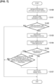
- Figure 7 shows an example of the flow of operations of the travel control device 1 during manual driving travel of vehicle V.
- the absolute position estimation unit 23 estimates the absolute position of vehicle V on a map based on the self-location of vehicle V acquired from the GNSS receiver 13 as well as the vehicle speed and angular velocity.
- the relative position estimation unit 22 estimates the relative position and the relative azimuth angle of vehicle V in a relative coordinate system, with the absolute position of vehicle V estimated by the absolute position estimation unit 23 as the origin.
- Step S101 the lane boundary line detection unit 21 detects, from images captured by the camera 10, lane boundary lines in front of the vehicle provided at the widthwise ends of the host vehicle lane in which vehicle V is traveling.
- Step S102 the lane boundary line detection unit 21 determines whether the lane boundary lines have been successively detected. If lane boundary lines have been successively detected (YES in Step S102), the process proceeds to Step S103. On the other hand, if the lane boundary lines have not been detected (NO in Step S102), the process of Figure 7 is terminated.
- Step S103 the travel path calculation unit 24 calculates and stores a prescribed position with respect to the lane boundary lines detected by the lane boundary line detection unit 21.
- the travel path calculation unit 24 calculates and stores the direction along the host vehicle lane at the calculated prescribed position.
- Step S104 the travel path calculation unit 24 checks the operating state of the turn indicator of vehicle V as vehicle V travels in the section from the previously stored prescribed position (first prescribed position) to the currently stored prescribed position (second prescribed position).
- Step S105 if the turn indicator of vehicle V has been activated as vehicle V travels in the section from the first prescribed position to the second prescribed position (YES in Step S105), the process proceeds to Step S106.
- Step S107 if the turn indicator of vehicle V has not been activated as vehicle V travels in the section from the first prescribed position to the second prescribed position (NO in Step S105), the process proceeds to Step S107.
- Step S106 the travel path calculation unit 24 determines whether a deviation of a prescribed value or more exists between the azimuth angles of vehicle V at the first and second points or between the first and second prescribed positions. If a deviation of a prescribed value or more exists between the azimuth angles of vehicle V at the first and second points or between the first and second prescribed positions (YES in Step S106), the process proceeds to Step S107. If a deviation of the prescribed value or more does not exist between the azimuth angles of vehicle V at the first and second points or between the first and second prescribed positions (NO in Step S106), the process of Figure 7 is terminated.
- Step S107 the travel path calculation unit 24 calculates a travel path connecting the stored first and second prescribed positions.
- a case is considered in which the state changes from one in which the lane boundary lines can be detected, to one in which the lane boundary lines can no longer be detected, and then to one in which the lane boundary lines can again be detected.
- the point at which the state changes from one in which the lane boundary lines can be detected to a state in which lane dividing lines cannot be detected is the first point, and the prescribed position relative to the lane boundary lines at this first point is the first prescribed position.
- the point at which the state changes from one in which the lane boundary lines cannot be detected to a state in which the lane boundary lines can be detected is the second point, and the prescribed position relative to the lane boundary lines at this second point is the second prescribed position.
- the point at which the state changes from one in which lane boundary lines are detectable to a state in which lane boundary lines are not detectable is the first point
- the point at which the state changes from one in which the lane boundary lines are not detectable to a state in which the lane boundary lines are detectable is the second point, but no limitation is implied thereby.
- the first point may be the point at a prescribed time before the time at which the state changes from one in which the lane boundary lines are detectable to a state in which the lane boundary lines are undetectable.
- the second point may be the point at a prescribed time after the time at which the state changes from one in which the lane boundary lines are undetectable to a state in which the lane boundary lines are detectable.
- the travel path calculation unit 24 calculates a travel path connecting the first and second prescribed positions such that its orientation matches the direction along the host vehicle lane at the first prescribed position and/or the direction along the host vehicle lane at the second prescribed position.
- the travel path storage unit 25 stores in memory in the controller 20 the absolute position and the azimuth angle of vehicle V at the first point, the positions of the lane boundary lines detected by vehicle V at the first point, and the first and second prescribed positions and the travel path calculated by the travel path calculation unit 24 as a set.
- Figure 8 shows an example of the flow of operations of the travel control device 1 during autonomous driving travel of vehicle V.
- the absolute position estimation unit 23 estimates the absolute position of vehicle V on a map based on the self-location of vehicle V acquired from the GNSS receiver 13 and the vehicle speed and angular velocity.
- the relative position estimation unit 22 estimates the relative position and the relative azimuth angle of vehicle V in a relative coordinate system, with the absolute position of vehicle V estimated by the absolute position estimation unit 23 as the origin.
- Step S201 the travel path retrieval unit 26 extracts the travel path closest to the current absolute position of vehicle V within a prescribed range from the current absolute position of vehicle V from the absolute positions stored in the travel path storage unit 25.
- the absolute position and the absolute azimuth angle of vehicle V and the positions of the lane boundary lines stored as a set with the retrieved travel path are then extracted.
- Step S202 the travel path correction unit 27 determines whether the current absolute position and the current azimuth angle of vehicle V deviate by a prescribed value or more from the absolute position and the absolute azimuth angle of vehicle V extracted by the travel path retrieval unit 26. If the current absolute position and the current absolute azimuth angle of vehicle V deviated by the prescribed value or more from the absolute position and the azimuth angle of vehicle V extracted by the travel path retrieval unit 26 (YES in Step S202), then the travel path calculation unit 24 terminates the process of Figure 8 .
- Step S203 if the current absolute position and the current absolute azimuth angle of vehicle V do not deviate by a prescribed value or more from the absolute position and the absolute azimuth angle of vehicle V extracted by the travel path retrieval unit 26 (NO in Step S202), the process proceeds to Step S203.
- Step S203 the lane boundary line detection unit 21 detects, from images captured by the camera 10, lane boundary lines in front of the vehicle provided at the widthwise ends of the host vehicle lane in which vehicle V is traveling. Proceeding to Step S204, the lane boundary line detection unit 21 determines whether the lane boundary lines have been successfully detected. If the lane boundary lines have been successfully detected (YES in Step S204), the process proceeds to Step S205. If the lane boundary lines have not been detected (NO in Step S204), the process proceeds to Step S206.
- Step S205 the travel path correction unit 27 associates the positions of the lane boundary lines retrieved by the travel path retrieval unit 26 in Step S201 with the positions of the lane boundary lines detected by the lane boundary line detection unit 21 in Step S203.
- a coordinate transformation (translation/rotation) T is then calculated so that the positions of the lane boundary lines retrieved by the travel path retrieval unit 26 in Step S201 match the positions of the lane boundary lines detected by the lane boundary line detection unit 21 in Step S203 to the extent possible.
- the travel path correction unit 27 applies the calculated coordinate transformation T to the travel path retrieved by the travel path calculation unit 24 in Step S201 so that it is corrected to a relative travel path with respect to the current vehicle V.
- the corrected travel path is then set as the travel path of current vehicle V.
- Step S206 the vehicle control unit 28 controls the actuators of vehicle V such that vehicle V follows the travel path corrected by the travel path correction unit 27, and the process of Figure 8 is terminated.
- the travel path connecting the first and second prescribed positions is corrected to a relative travel path with respect to the current vehicle V.
- a first target present in the vicinity of the host vehicle at a first point may be detected and stored, and when vehicle V travels in a section for which first and second prescribed positions are stored, a second target corresponding to the first target may be detected and stored, and the travel path may be corrected based on the positional deviation between the first and second targets.
- the travel path storage unit 25 stores in memory in the controller 20 the absolute position and the absolute azimuth angle of vehicle V at the first point, the positions of the first target detected at the first point, and the first and second prescribed positions and the travel path calculated by the travel path calculation unit 24 as a set. Then, based on the difference between the position of the first target stored as a set with the travel path extracted by the travel path retrieval unit 26 and the position of the second target corresponding to the first target detected by the current vehicle V, the travel path correction unit 27 corrects the travel path extracted by the travel path retrieval unit 26 to a relative travel path with respect to the current vehicle V.
- the first and second targets may be any one of lane boundary lines, stop lines, traffic lights, road signs, road markings, or a combination thereof.
- the travel control device comprises a controller that detects lane boundary lines provided at the widthwise ends of a host vehicle lane in which a host vehicle is traveling and performs travel control of the host vehicle based on the detection result of the lane boundary lines.
- a first prescribed position with respect to the lane boundary lines is calculated and stored when changing from a state in which the lane boundary lines can be detected to a state in which the lane boundary lines cannot be detected, and a second prescribed position with respect to the lane boundary lines is calculated and stored when changing from a state in which the lane boundary lines cannot be detected to a state in which the lane boundary lines can be detected.
- the host vehicle is then controlled to travel along a travel path connecting the first prescribed position and the second prescribed position during travel in a section for which the first and second prescribed positions are stored.
- the travel control device calculates the lane widthwise center position of the host vehicle lane as the first and second prescribed positions with respect to the lane boundary lines.
- this allows travel in the center position of the lane, even in sections such as intersections in which lane boundary lines cannot be detected.
- the travel control device calculates and stores the direction along the host vehicle lane at the first and second prescribed positions, and calculates a travel path that connects the first and second prescribed positions such that its orientation matches the direction along the host vehicle lane at the first prescribed position and/or the direction along the host vehicle lane at the second prescribed position. It is thus possible to set a travel path whose orientation matches the orientation of the host vehicle at the first prescribed position and the direction of the host vehicle lane at the second prescribed position. Even in a case in which the orientation of the host vehicle lane at the first prescribed position and the orientation of the host vehicle lane at the second prescribed position significantly differ, such as when the host vehicle turns left or right, or travels along a curve, it is possible to travel in the prescribed position of the lane.
- the travel control device detects and stores a first target present in the vicinity of the host vehicle when the first prescribed position is calculated and stored, and detects a second target corresponding to the first target during travel in a section for which first and second prescribed positions are stored, and corrects the travel path based on the positional deviation between the first target and the second target. Therefore, it is possible to calculate the positional deviation between the first target detected when the first prescribed position was calculated and the second target corresponding to the second target detected during travel in a section for which first and second prescribed positions are stored.
- the first and second targets may be any one of lane boundary lines, stop lines, traffic lights, road signs, road markings, or a combination thereof. It is thus possible to select one or a more detectable targets from among targets present in the vicinity of the vehicle. It is thus also possible to more accurately correct the errors in the position of the host vehicle when the first prescribed position is calculated, and the position of the host vehicle during travel in a section for which first and second prescribed positions are stored, and to suppress errors in the positions of the travel path connecting the first and second prescribed positions.
- the travel control device calculates the travel path if a deviation of a prescribed value or more exists between the first and second prescribed positions, or between the attitudes of the host vehicle when the first and second prescribed positions were calculated, and does not calculate a travel path if a deviation of a prescribed value or more does not exist. Therefore, in the case that there is a deviation between the first and second prescribed positions, such as when the host vehicle turns right or left, or travels along a curve, or a case in which the attitudes of the host vehicle are respectively different when the first and second prescribed positions are calculated, a travel path connecting the first and second prescribed positions is calculated.
- first and second prescribed positions do not diverge, such as when the host vehicle changes lanes, or when the attitude of the host vehicle does not deviate at between he first and second prescribed positions when these positions are calculated, a travel path connecting the first and second prescribed positions is not calculated.
- the turn indicator when activated, it is possible to set separate travel paths for host vehicle right/left turns and host vehicle lane changes, thereby preventing the setting of an unsuitable travel path.
- the travel control device does not set the calculated travel path as the travel path of the host vehicle. Therefore, if the host vehicle is traveling in a state in which the host vehicle deviates significantly from its own lane, a travel path is not set, and thus the setting of an unsuitable travel path can be prevented.
Landscapes
- Engineering & Computer Science (AREA)
- Automation & Control Theory (AREA)
- Transportation (AREA)
- Mechanical Engineering (AREA)
- Physics & Mathematics (AREA)
- General Physics & Mathematics (AREA)
- Human Computer Interaction (AREA)
- Multimedia (AREA)
- Theoretical Computer Science (AREA)
- Traffic Control Systems (AREA)
- Control Of Driving Devices And Active Controlling Of Vehicle (AREA)
Applications Claiming Priority (1)
| Application Number | Priority Date | Filing Date | Title |
|---|---|---|---|
| PCT/IB2020/000979 WO2022112811A1 (ja) | 2020-11-27 | 2020-11-27 | 走行制御方法及び走行制御装置 |
Publications (3)
| Publication Number | Publication Date |
|---|---|
| EP4254381A1 EP4254381A1 (en) | 2023-10-04 |
| EP4254381A4 EP4254381A4 (en) | 2024-01-10 |
| EP4254381B1 true EP4254381B1 (en) | 2024-10-23 |
Family
ID=81754117
Family Applications (1)
| Application Number | Title | Priority Date | Filing Date |
|---|---|---|---|
| EP20963401.3A Active EP4254381B1 (en) | 2020-11-27 | 2020-11-27 | Travel control method and travel control device |
Country Status (5)
| Country | Link |
|---|---|
| US (1) | US11840226B1 (https=) |
| EP (1) | EP4254381B1 (https=) |
| JP (1) | JP7422248B2 (https=) |
| CN (1) | CN116547730B (https=) |
| WO (1) | WO2022112811A1 (https=) |
Families Citing this family (3)
| Publication number | Priority date | Publication date | Assignee | Title |
|---|---|---|---|---|
| EP4306376A4 (en) * | 2021-03-11 | 2024-09-04 | Hitachi Astemo, Ltd. | VEHICLE CONTROL DEVICE, VEHICLE CONTROL METHOD, TARGET TRAJECTORY CALCULATION METHOD, AND VEHICLE |
| CN114179805B (zh) * | 2021-12-10 | 2023-12-19 | 北京百度网讯科技有限公司 | 一种行驶方向确定方法、装置、设备以及存储介质 |
| US20240416909A1 (en) * | 2023-06-16 | 2024-12-19 | Magna Electronics Inc. | Vehicular driving assistance system with vehicle state estimation |
Family Cites Families (23)
| Publication number | Priority date | Publication date | Assignee | Title |
|---|---|---|---|---|
| CN101290230B (zh) * | 2008-04-14 | 2011-03-30 | 深圳市凯立德软件技术股份有限公司 | 一种交叉路口的导航方法及使用了此导航方法的导航系统 |
| JP5007840B2 (ja) | 2009-05-22 | 2012-08-22 | トヨタ自動車株式会社 | 運転支援装置 |
| CN102667888B (zh) * | 2009-11-27 | 2014-12-31 | 丰田自动车株式会社 | 驾驶辅助装置以及驾驶辅助方法 |
| JP5708449B2 (ja) * | 2011-11-08 | 2015-04-30 | アイシン・エィ・ダブリュ株式会社 | レーン案内表示システム、方法およびプログラム |
| EP2871107B1 (en) * | 2012-07-06 | 2023-10-25 | Toyota Jidosha Kabushiki Kaisha | Traveling control device for vehicle |
| US20140267415A1 (en) * | 2013-03-12 | 2014-09-18 | Xueming Tang | Road marking illuminattion system and method |
| JP6197393B2 (ja) * | 2013-06-20 | 2017-09-20 | 株式会社豊田中央研究所 | レーン地図生成装置及びプログラム |
| JP2016218539A (ja) | 2015-05-15 | 2016-12-22 | トヨタ自動車株式会社 | 車両の走路認識装置 |
| JP6564618B2 (ja) | 2015-05-28 | 2019-08-21 | アイシン・エィ・ダブリュ株式会社 | 道路形状検出システム、道路形状検出方法及びコンピュータプログラム |
| DE102015211150B4 (de) * | 2015-06-17 | 2023-05-11 | Bayerische Motoren Werke Aktiengesellschaft | Verfahren, Fahrerassistenzsystem und Fahrzeug zum Lernen einer Trajektorie eines Straßenabschnitts |
| CN105787455A (zh) * | 2016-03-01 | 2016-07-20 | 江苏大学 | 一种引入图像虚拟引导线的车道保持控制算法 |
| RU2742222C2 (ru) * | 2016-07-12 | 2021-02-03 | Ниссан Мотор Ко., Лтд. | Способ управления движением транспортного средства и устройство управления движением транспортного средства |
| CN106023606B (zh) * | 2016-07-15 | 2018-12-04 | 珠海达理宇航科技有限公司 | 交叉口的路口结构及其两次变左控制方法 |
| JP2019012308A (ja) | 2017-06-29 | 2019-01-24 | 株式会社デンソーテン | 画像処理装置及び画像処理方法 |
| US11352009B2 (en) * | 2017-10-10 | 2022-06-07 | Honda Motor Co., Ltd. | Vehicle control apparatus, vehicle control method, and program |
| CN107963077B (zh) * | 2017-10-26 | 2020-02-21 | 东软集团股份有限公司 | 一种车辆通过路口的控制方法、装置及系统 |
| US11181920B2 (en) * | 2018-08-28 | 2021-11-23 | Denso Corporation | Travel assistance method and travel assistance apparatus |
| US10703365B1 (en) * | 2018-12-26 | 2020-07-07 | Automotive Research & Testing Center | Lane tracking method and lane tracking system for an autonomous vehicle |
| CN110909711B (zh) * | 2019-12-03 | 2022-08-02 | 阿波罗智能技术(北京)有限公司 | 检测车道线位置变化的方法、装置、电子设备和存储介质 |
| CN110954128B (zh) * | 2019-12-03 | 2021-11-16 | 阿波罗智能技术(北京)有限公司 | 检测车道线位置变化的方法、装置、电子设备和存储介质 |
| US11560131B2 (en) * | 2020-01-13 | 2023-01-24 | Nio Technology (Anhui) Co., Ltd. | Lane prediction and smoothing for extended motion planning horizon |
| FR3107589B1 (fr) * | 2020-02-21 | 2022-03-18 | Commissariat Energie Atomique | Procédé de détermination de la position et de l’orientation d’un véhicule. |
| JP7191065B2 (ja) * | 2020-07-06 | 2022-12-16 | 本田技研工業株式会社 | 処理装置、処理方法、およびプログラム |
-
2020
- 2020-11-27 CN CN202080107526.3A patent/CN116547730B/zh active Active
- 2020-11-27 US US18/036,208 patent/US11840226B1/en active Active
- 2020-11-27 EP EP20963401.3A patent/EP4254381B1/en active Active
- 2020-11-27 WO PCT/IB2020/000979 patent/WO2022112811A1/ja not_active Ceased
- 2020-11-27 JP JP2022564700A patent/JP7422248B2/ja active Active
Also Published As
| Publication number | Publication date |
|---|---|
| US20230391325A1 (en) | 2023-12-07 |
| EP4254381A1 (en) | 2023-10-04 |
| WO2022112811A1 (ja) | 2022-06-02 |
| JPWO2022112811A1 (https=) | 2022-06-02 |
| JP7422248B2 (ja) | 2024-01-25 |
| US11840226B1 (en) | 2023-12-12 |
| CN116547730A (zh) | 2023-08-04 |
| CN116547730B (zh) | 2025-02-21 |
| EP4254381A4 (en) | 2024-01-10 |
Similar Documents
| Publication | Publication Date | Title |
|---|---|---|
| US10793141B2 (en) | Vehicle traveling control apparatus | |
| US11526173B2 (en) | Traveling trajectory correction method, traveling control method, and traveling trajectory correction device | |
| CN111066071B (zh) | 驾驶辅助车辆的位置误差校正方法及位置误差校正装置 | |
| EP3480560B1 (en) | Vehicle localization device | |
| US11904936B2 (en) | Driving support device for vehicle | |
| JP5747787B2 (ja) | 車線認識装置 | |
| US20180281789A1 (en) | Traveling controller for vehicle | |
| EP4254381B1 (en) | Travel control method and travel control device | |
| US11468772B2 (en) | Vehicle drive-assist apparatus | |
| EP4046894B1 (en) | Overriding determination method for travel assistance device, and travel assistance device | |
| CN114526747A (zh) | 用于视觉转向的自动化车辆的车道延伸 | |
| JP6943127B2 (ja) | 位置補正方法、車両制御方法及び位置補正装置 | |
| JP2021092508A (ja) | 走行軌跡推定方法及び走行軌跡推定装置 | |
| US11919567B2 (en) | Automatic steering control apparatus | |
| US20230286583A1 (en) | Vehicle Control Device, Vehicle Control Method, and Vehicle Control System | |
| US11845436B2 (en) | Vehicle travel locus transmission system and vehicle traffic control system | |
| JP3797188B2 (ja) | コーナー開始点・道路分岐点検出装置 | |
| WO2022070458A1 (ja) | 自車位置推定装置及び自車位置推定方法 | |
| CN114523968A (zh) | 周围车辆监测装置和周围车辆监测方法 | |
| US20250333054A1 (en) | Steering control device | |
| JP7532240B2 (ja) | 走行支援方法及び走行支援装置 | |
| CN120534425A (zh) | 行驶控制装置 | |
| CN118524956A (zh) | 用于车辆在具有分支的道路上的自动横向引导期间辅助车辆的用户的方法、计算装置和驾驶员辅助系统 | |
| JP2023064971A (ja) | 車両位置補正システム |
Legal Events
| Date | Code | Title | Description |
|---|---|---|---|
| STAA | Information on the status of an ep patent application or granted ep patent |
Free format text: STATUS: THE INTERNATIONAL PUBLICATION HAS BEEN MADE |
|
| PUAI | Public reference made under article 153(3) epc to a published international application that has entered the european phase |
Free format text: ORIGINAL CODE: 0009012 |
|
| STAA | Information on the status of an ep patent application or granted ep patent |
Free format text: STATUS: REQUEST FOR EXAMINATION WAS MADE |
|
| 17P | Request for examination filed |
Effective date: 20230622 |
|
| AK | Designated contracting states |
Kind code of ref document: A1 Designated state(s): AL AT BE BG CH CY CZ DE DK EE ES FI FR GB GR HR HU IE IS IT LI LT LU LV MC MK MT NL NO PL PT RO RS SE SI SK SM TR |
|
| A4 | Supplementary search report drawn up and despatched |
Effective date: 20231211 |
|
| RIC1 | Information provided on ipc code assigned before grant |
Ipc: G08G 1/16 20060101ALI20231205BHEP Ipc: G08G 1/01 20060101AFI20231205BHEP |
|
| DAV | Request for validation of the european patent (deleted) | ||
| DAX | Request for extension of the european patent (deleted) | ||
| GRAP | Despatch of communication of intention to grant a patent |
Free format text: ORIGINAL CODE: EPIDOSNIGR1 |
|
| STAA | Information on the status of an ep patent application or granted ep patent |
Free format text: STATUS: GRANT OF PATENT IS INTENDED |
|
| INTG | Intention to grant announced |
Effective date: 20240725 |
|
| GRAS | Grant fee paid |
Free format text: ORIGINAL CODE: EPIDOSNIGR3 |
|
| GRAA | (expected) grant |
Free format text: ORIGINAL CODE: 0009210 |
|
| STAA | Information on the status of an ep patent application or granted ep patent |
Free format text: STATUS: THE PATENT HAS BEEN GRANTED |
|
| AK | Designated contracting states |
Kind code of ref document: B1 Designated state(s): AL AT BE BG CH CY CZ DE DK EE ES FI FR GB GR HR HU IE IS IT LI LT LU LV MC MK MT NL NO PL PT RO RS SE SI SK SM TR |
|
| REG | Reference to a national code |
Ref country code: GB Ref legal event code: FG4D |
|
| REG | Reference to a national code |
Ref country code: CH Ref legal event code: EP |
|
| REG | Reference to a national code |
Ref country code: DE Ref legal event code: R096 Ref document number: 602020040118 Country of ref document: DE |
|
| REG | Reference to a national code |
Ref country code: IE Ref legal event code: FG4D |
|
| REG | Reference to a national code |
Ref country code: LT Ref legal event code: MG9D |
|
| REG | Reference to a national code |
Ref country code: NL Ref legal event code: MP Effective date: 20241023 |
|
| REG | Reference to a national code |
Ref country code: AT Ref legal event code: MK05 Ref document number: 1735504 Country of ref document: AT Kind code of ref document: T Effective date: 20241023 |
|
| PG25 | Lapsed in a contracting state [announced via postgrant information from national office to epo] |
Ref country code: NL Free format text: LAPSE BECAUSE OF FAILURE TO SUBMIT A TRANSLATION OF THE DESCRIPTION OR TO PAY THE FEE WITHIN THE PRESCRIBED TIME-LIMIT Effective date: 20241023 |
|
| PG25 | Lapsed in a contracting state [announced via postgrant information from national office to epo] |
Ref country code: NL Free format text: LAPSE BECAUSE OF FAILURE TO SUBMIT A TRANSLATION OF THE DESCRIPTION OR TO PAY THE FEE WITHIN THE PRESCRIBED TIME-LIMIT Effective date: 20241023 |
|
| PG25 | Lapsed in a contracting state [announced via postgrant information from national office to epo] |
Ref country code: IS Free format text: LAPSE BECAUSE OF FAILURE TO SUBMIT A TRANSLATION OF THE DESCRIPTION OR TO PAY THE FEE WITHIN THE PRESCRIBED TIME-LIMIT Effective date: 20250223 Ref country code: PT Free format text: LAPSE BECAUSE OF FAILURE TO SUBMIT A TRANSLATION OF THE DESCRIPTION OR TO PAY THE FEE WITHIN THE PRESCRIBED TIME-LIMIT Effective date: 20250224 Ref country code: HR Free format text: LAPSE BECAUSE OF FAILURE TO SUBMIT A TRANSLATION OF THE DESCRIPTION OR TO PAY THE FEE WITHIN THE PRESCRIBED TIME-LIMIT Effective date: 20241023 |
|
| PG25 | Lapsed in a contracting state [announced via postgrant information from national office to epo] |
Ref country code: FI Free format text: LAPSE BECAUSE OF FAILURE TO SUBMIT A TRANSLATION OF THE DESCRIPTION OR TO PAY THE FEE WITHIN THE PRESCRIBED TIME-LIMIT Effective date: 20241023 |
|
| PG25 | Lapsed in a contracting state [announced via postgrant information from national office to epo] |
Ref country code: BG Free format text: LAPSE BECAUSE OF FAILURE TO SUBMIT A TRANSLATION OF THE DESCRIPTION OR TO PAY THE FEE WITHIN THE PRESCRIBED TIME-LIMIT Effective date: 20241023 |
|
| PG25 | Lapsed in a contracting state [announced via postgrant information from national office to epo] |
Ref country code: ES Free format text: LAPSE BECAUSE OF FAILURE TO SUBMIT A TRANSLATION OF THE DESCRIPTION OR TO PAY THE FEE WITHIN THE PRESCRIBED TIME-LIMIT Effective date: 20241023 |
|
| PG25 | Lapsed in a contracting state [announced via postgrant information from national office to epo] |
Ref country code: NO Free format text: LAPSE BECAUSE OF FAILURE TO SUBMIT A TRANSLATION OF THE DESCRIPTION OR TO PAY THE FEE WITHIN THE PRESCRIBED TIME-LIMIT Effective date: 20250123 |
|
| PG25 | Lapsed in a contracting state [announced via postgrant information from national office to epo] |
Ref country code: AT Free format text: LAPSE BECAUSE OF FAILURE TO SUBMIT A TRANSLATION OF THE DESCRIPTION OR TO PAY THE FEE WITHIN THE PRESCRIBED TIME-LIMIT Effective date: 20241023 Ref country code: GR Free format text: LAPSE BECAUSE OF FAILURE TO SUBMIT A TRANSLATION OF THE DESCRIPTION OR TO PAY THE FEE WITHIN THE PRESCRIBED TIME-LIMIT Effective date: 20250124 Ref country code: LV Free format text: LAPSE BECAUSE OF FAILURE TO SUBMIT A TRANSLATION OF THE DESCRIPTION OR TO PAY THE FEE WITHIN THE PRESCRIBED TIME-LIMIT Effective date: 20241023 |
|
| PG25 | Lapsed in a contracting state [announced via postgrant information from national office to epo] |
Ref country code: PL Free format text: LAPSE BECAUSE OF FAILURE TO SUBMIT A TRANSLATION OF THE DESCRIPTION OR TO PAY THE FEE WITHIN THE PRESCRIBED TIME-LIMIT Effective date: 20241023 |
|
| PG25 | Lapsed in a contracting state [announced via postgrant information from national office to epo] |
Ref country code: RS Free format text: LAPSE BECAUSE OF FAILURE TO SUBMIT A TRANSLATION OF THE DESCRIPTION OR TO PAY THE FEE WITHIN THE PRESCRIBED TIME-LIMIT Effective date: 20250123 |
|
| REG | Reference to a national code |
Ref country code: CH Ref legal event code: PL |
|
| PG25 | Lapsed in a contracting state [announced via postgrant information from national office to epo] |
Ref country code: SM Free format text: LAPSE BECAUSE OF FAILURE TO SUBMIT A TRANSLATION OF THE DESCRIPTION OR TO PAY THE FEE WITHIN THE PRESCRIBED TIME-LIMIT Effective date: 20241023 |
|
| PG25 | Lapsed in a contracting state [announced via postgrant information from national office to epo] |
Ref country code: MC Free format text: LAPSE BECAUSE OF FAILURE TO SUBMIT A TRANSLATION OF THE DESCRIPTION OR TO PAY THE FEE WITHIN THE PRESCRIBED TIME-LIMIT Effective date: 20241023 |
|
| PG25 | Lapsed in a contracting state [announced via postgrant information from national office to epo] |
Ref country code: DK Free format text: LAPSE BECAUSE OF FAILURE TO SUBMIT A TRANSLATION OF THE DESCRIPTION OR TO PAY THE FEE WITHIN THE PRESCRIBED TIME-LIMIT Effective date: 20241023 |
|
| PG25 | Lapsed in a contracting state [announced via postgrant information from national office to epo] |
Ref country code: LU Free format text: LAPSE BECAUSE OF NON-PAYMENT OF DUE FEES Effective date: 20241127 |
|
| REG | Reference to a national code |
Ref country code: CH Ref legal event code: PL |
|
| PG25 | Lapsed in a contracting state [announced via postgrant information from national office to epo] |
Ref country code: EE Free format text: LAPSE BECAUSE OF FAILURE TO SUBMIT A TRANSLATION OF THE DESCRIPTION OR TO PAY THE FEE WITHIN THE PRESCRIBED TIME-LIMIT Effective date: 20241023 |
|
| PG25 | Lapsed in a contracting state [announced via postgrant information from national office to epo] |
Ref country code: CH Free format text: LAPSE BECAUSE OF NON-PAYMENT OF DUE FEES Effective date: 20241130 |
|
| PG25 | Lapsed in a contracting state [announced via postgrant information from national office to epo] |
Ref country code: RO Free format text: LAPSE BECAUSE OF FAILURE TO SUBMIT A TRANSLATION OF THE DESCRIPTION OR TO PAY THE FEE WITHIN THE PRESCRIBED TIME-LIMIT Effective date: 20241023 |
|
| REG | Reference to a national code |
Ref country code: DE Ref legal event code: R097 Ref document number: 602020040118 Country of ref document: DE |
|
| PG25 | Lapsed in a contracting state [announced via postgrant information from national office to epo] |
Ref country code: SK Free format text: LAPSE BECAUSE OF FAILURE TO SUBMIT A TRANSLATION OF THE DESCRIPTION OR TO PAY THE FEE WITHIN THE PRESCRIBED TIME-LIMIT Effective date: 20241023 |
|
| PG25 | Lapsed in a contracting state [announced via postgrant information from national office to epo] |
Ref country code: CZ Free format text: LAPSE BECAUSE OF FAILURE TO SUBMIT A TRANSLATION OF THE DESCRIPTION OR TO PAY THE FEE WITHIN THE PRESCRIBED TIME-LIMIT Effective date: 20241023 |
|
| PG25 | Lapsed in a contracting state [announced via postgrant information from national office to epo] |
Ref country code: IT Free format text: LAPSE BECAUSE OF FAILURE TO SUBMIT A TRANSLATION OF THE DESCRIPTION OR TO PAY THE FEE WITHIN THE PRESCRIBED TIME-LIMIT Effective date: 20241023 |
|
| REG | Reference to a national code |
Ref country code: BE Ref legal event code: MM Effective date: 20241130 |
|
| PLBE | No opposition filed within time limit |
Free format text: ORIGINAL CODE: 0009261 |
|
| STAA | Information on the status of an ep patent application or granted ep patent |
Free format text: STATUS: NO OPPOSITION FILED WITHIN TIME LIMIT |
|
| PG25 | Lapsed in a contracting state [announced via postgrant information from national office to epo] |
Ref country code: SE Free format text: LAPSE BECAUSE OF FAILURE TO SUBMIT A TRANSLATION OF THE DESCRIPTION OR TO PAY THE FEE WITHIN THE PRESCRIBED TIME-LIMIT Effective date: 20241023 |
|
| 26N | No opposition filed |
Effective date: 20250724 |
|
| PG25 | Lapsed in a contracting state [announced via postgrant information from national office to epo] |
Ref country code: BE Free format text: LAPSE BECAUSE OF NON-PAYMENT OF DUE FEES Effective date: 20241130 |
|
| PG25 | Lapsed in a contracting state [announced via postgrant information from national office to epo] |
Ref country code: IE Free format text: LAPSE BECAUSE OF NON-PAYMENT OF DUE FEES Effective date: 20241127 |
|
| PGFP | Annual fee paid to national office [announced via postgrant information from national office to epo] |
Ref country code: DE Payment date: 20251022 Year of fee payment: 6 |
|
| PGFP | Annual fee paid to national office [announced via postgrant information from national office to epo] |
Ref country code: GB Payment date: 20251022 Year of fee payment: 6 |
|
| PGFP | Annual fee paid to national office [announced via postgrant information from national office to epo] |
Ref country code: FR Payment date: 20251022 Year of fee payment: 6 |
|
| PG25 | Lapsed in a contracting state [announced via postgrant information from national office to epo] |
Ref country code: HU Free format text: LAPSE BECAUSE OF FAILURE TO SUBMIT A TRANSLATION OF THE DESCRIPTION OR TO PAY THE FEE WITHIN THE PRESCRIBED TIME-LIMIT; INVALID AB INITIO Effective date: 20201127 |
|
| PG25 | Lapsed in a contracting state [announced via postgrant information from national office to epo] |
Ref country code: CY Free format text: LAPSE BECAUSE OF FAILURE TO SUBMIT A TRANSLATION OF THE DESCRIPTION OR TO PAY THE FEE WITHIN THE PRESCRIBED TIME-LIMIT; INVALID AB INITIO Effective date: 20201127 |