WO2022112811A1 - 走行制御方法及び走行制御装置 - Google Patents
走行制御方法及び走行制御装置 Download PDFInfo
- Publication number
- WO2022112811A1 WO2022112811A1 PCT/IB2020/000979 IB2020000979W WO2022112811A1 WO 2022112811 A1 WO2022112811 A1 WO 2022112811A1 IB 2020000979 W IB2020000979 W IB 2020000979W WO 2022112811 A1 WO2022112811 A1 WO 2022112811A1
- Authority
- WO
- WIPO (PCT)
- Prior art keywords
- vehicle
- lane
- track
- predetermined position
- dividing line
- Prior art date
Links
- 238000000034 method Methods 0.000 title claims description 34
- 238000001514 detection method Methods 0.000 claims abstract description 23
- 230000036544 posture Effects 0.000 claims description 12
- 238000004364 calculation method Methods 0.000 description 48
- 230000008569 process Effects 0.000 description 11
- 238000010586 diagram Methods 0.000 description 7
- 230000010365 information processing Effects 0.000 description 6
- 238000006243 chemical reaction Methods 0.000 description 3
- 230000006870 function Effects 0.000 description 3
- 238000004590 computer program Methods 0.000 description 2
- 239000000284 extract Substances 0.000 description 2
- 230000009466 transformation Effects 0.000 description 2
- 230000001133 acceleration Effects 0.000 description 1
- 230000008859 change Effects 0.000 description 1
- 230000000295 complement effect Effects 0.000 description 1
- 230000000694 effects Effects 0.000 description 1
- 230000004907 flux Effects 0.000 description 1
- 229910044991 metal oxide Inorganic materials 0.000 description 1
- 150000004706 metal oxides Chemical class 0.000 description 1
- 239000004065 semiconductor Substances 0.000 description 1
Images


Classifications
-
- B—PERFORMING OPERATIONS; TRANSPORTING
- B60—VEHICLES IN GENERAL
- B60W—CONJOINT CONTROL OF VEHICLE SUB-UNITS OF DIFFERENT TYPE OR DIFFERENT FUNCTION; CONTROL SYSTEMS SPECIALLY ADAPTED FOR HYBRID VEHICLES; ROAD VEHICLE DRIVE CONTROL SYSTEMS FOR PURPOSES NOT RELATED TO THE CONTROL OF A PARTICULAR SUB-UNIT
- B60W30/00—Purposes of road vehicle drive control systems not related to the control of a particular sub-unit, e.g. of systems using conjoint control of vehicle sub-units
- B60W30/18—Propelling the vehicle
- B60W30/18009—Propelling the vehicle related to particular drive situations
- B60W30/18159—Traversing an intersection
-
- B—PERFORMING OPERATIONS; TRANSPORTING
- B60—VEHICLES IN GENERAL
- B60W—CONJOINT CONTROL OF VEHICLE SUB-UNITS OF DIFFERENT TYPE OR DIFFERENT FUNCTION; CONTROL SYSTEMS SPECIALLY ADAPTED FOR HYBRID VEHICLES; ROAD VEHICLE DRIVE CONTROL SYSTEMS FOR PURPOSES NOT RELATED TO THE CONTROL OF A PARTICULAR SUB-UNIT
- B60W30/00—Purposes of road vehicle drive control systems not related to the control of a particular sub-unit, e.g. of systems using conjoint control of vehicle sub-units
- B60W30/10—Path keeping
- B60W30/12—Lane keeping
-
- B—PERFORMING OPERATIONS; TRANSPORTING
- B60—VEHICLES IN GENERAL
- B60W—CONJOINT CONTROL OF VEHICLE SUB-UNITS OF DIFFERENT TYPE OR DIFFERENT FUNCTION; CONTROL SYSTEMS SPECIALLY ADAPTED FOR HYBRID VEHICLES; ROAD VEHICLE DRIVE CONTROL SYSTEMS FOR PURPOSES NOT RELATED TO THE CONTROL OF A PARTICULAR SUB-UNIT
- B60W60/00—Drive control systems specially adapted for autonomous road vehicles
- B60W60/001—Planning or execution of driving tasks
-
- G—PHYSICS
- G06—COMPUTING; CALCULATING OR COUNTING
- G06V—IMAGE OR VIDEO RECOGNITION OR UNDERSTANDING
- G06V20/00—Scenes; Scene-specific elements
- G06V20/50—Context or environment of the image
- G06V20/56—Context or environment of the image exterior to a vehicle by using sensors mounted on the vehicle
- G06V20/588—Recognition of the road, e.g. of lane markings; Recognition of the vehicle driving pattern in relation to the road
-
- G—PHYSICS
- G08—SIGNALLING
- G08G—TRAFFIC CONTROL SYSTEMS
- G08G1/00—Traffic control systems for road vehicles
- G08G1/16—Anti-collision systems
- G08G1/167—Driving aids for lane monitoring, lane changing, e.g. blind spot detection
-
- B—PERFORMING OPERATIONS; TRANSPORTING
- B60—VEHICLES IN GENERAL
- B60W—CONJOINT CONTROL OF VEHICLE SUB-UNITS OF DIFFERENT TYPE OR DIFFERENT FUNCTION; CONTROL SYSTEMS SPECIALLY ADAPTED FOR HYBRID VEHICLES; ROAD VEHICLE DRIVE CONTROL SYSTEMS FOR PURPOSES NOT RELATED TO THE CONTROL OF A PARTICULAR SUB-UNIT
- B60W2540/00—Input parameters relating to occupants
- B60W2540/20—Direction indicator values
-
- B—PERFORMING OPERATIONS; TRANSPORTING
- B60—VEHICLES IN GENERAL
- B60W—CONJOINT CONTROL OF VEHICLE SUB-UNITS OF DIFFERENT TYPE OR DIFFERENT FUNCTION; CONTROL SYSTEMS SPECIALLY ADAPTED FOR HYBRID VEHICLES; ROAD VEHICLE DRIVE CONTROL SYSTEMS FOR PURPOSES NOT RELATED TO THE CONTROL OF A PARTICULAR SUB-UNIT
- B60W2552/00—Input parameters relating to infrastructure
- B60W2552/53—Road markings, e.g. lane marker or crosswalk
-
- B—PERFORMING OPERATIONS; TRANSPORTING
- B60—VEHICLES IN GENERAL
- B60W—CONJOINT CONTROL OF VEHICLE SUB-UNITS OF DIFFERENT TYPE OR DIFFERENT FUNCTION; CONTROL SYSTEMS SPECIALLY ADAPTED FOR HYBRID VEHICLES; ROAD VEHICLE DRIVE CONTROL SYSTEMS FOR PURPOSES NOT RELATED TO THE CONTROL OF A PARTICULAR SUB-UNIT
- B60W2556/00—Input parameters relating to data
- B60W2556/10—Historical data
Definitions
- the present invention relates to a travel control method and a travel control device.
- Patent Document 1 discloses a road shape detecting method for accurately specifying the shape of a lane by combining the traveling information of a vehicle during autonomous driving and the traveling information of a vehicle during manual driving.
- the detection point (traveling locus) of the current position of the vehicle due to the passage of time during automatic driving is specified as the center line of the lane, and the center line of the specified lane and the passage of time during manual driving are elapsed. Identify the lane boundary based on the distribution of the distances of the detection points at the current position.
- the lane dividing line and other vehicles in the vicinity are detected by a camera or the like to execute automatic driving support of the vehicle, and the traveling locus of the vehicle during automatic driving is the center of the lane. It is specified as a line. Therefore, in the section where the lane dividing line is not partially drawn, or in the section where the lane dividing line is thinned to the extent that it disappears or cannot be recognized by a camera or the like, the center line of the lane and the boundary between the lanes are accurately defined. It is difficult to identify, and there is a risk that you will not be able to drive in a predetermined position in your lane.
- the present invention has been made in view of the above problems, and an object of the present invention is to provide a travel control method and a travel control device capable of traveling at a predetermined position in the own lane even in a section where a lane dividing line cannot be detected. It is to be.
- the traveling control method detects a lane dividing line provided at the widthwise end of the own lane in which the own vehicle is traveling, and travels the own vehicle based on the detection result of the lane dividing line. Take control.
- the first predetermined position with respect to the lane dividing line is calculated and stored, and when it becomes possible to detect from the state where the lane dividing line cannot be detected.
- the second predetermined position with respect to the lane dividing line is calculated and stored. Then, when traveling in the section in which the first and second predetermined positions are stored, the own vehicle is controlled so as to travel on the runway connecting the first predetermined position and the second predetermined position.
- the vehicle can travel at a predetermined position in the own lane.
- FIG. 1 is a block diagram showing a configuration example of a travel control device according to an embodiment of the present invention.
- FIG. 2 is a diagram illustrating an example of a track calculation method according to an embodiment of the present invention.
- FIG. 3 is a diagram illustrating an example of a track calculation method according to an embodiment of the present invention.
- FIG. 4 is a diagram illustrating an example of a track calculation method according to an embodiment of the present invention.
- FIG. 5 is a diagram illustrating an example of a track correction method according to an embodiment of the present invention.
- FIG. 6A is a diagram illustrating an example of a traveling scene according to an embodiment of the present invention.
- FIG. 6B is a diagram illustrating an example of a traveling scene according to the embodiment of the present invention.
- FIG. 7 is a flowchart illustrating an operation example of the travel control device according to the embodiment of the present invention.
- FIG. 8 is a flowchart illustrating an operation example of the traveling control device according to the embodiment of the present
- the travel control device 1 includes a camera 10, a vehicle speed sensor 11, an angular velocity sensor 12, a GNSS receiver 13, and a controller 20.
- the travel control device 1 according to the present embodiment is mounted on the vehicle V and controls the travel of the vehicle V.
- the travel control device 1 may be mounted on a vehicle having an automatic driving function, or may be mounted on a vehicle having no automatic driving function. Further, the travel control device 1 may be mounted on a vehicle capable of switching between automatic driving and manual driving.
- the automatic operation in the present embodiment refers to a state in which at least one of the actuators such as the brake, the accelerator, and the steering is controlled without the operation of the occupant. Therefore, other actuators may be operated by the operation of the occupant. Further, the automatic operation may be a state in which any control such as acceleration / deceleration control or lateral position control is executed.
- the manual operation in the present embodiment refers to a state in which the occupant is operating the brake, the accelerator, and the steering, for example.
- the camera 10 is mounted on the vehicle V and photographs the surroundings of the vehicle V.
- the camera 10 has an image pickup device such as a CCD (charge-coupled device) or a CMOS (complementary metal oxide semiconductor).
- the camera 10 sequentially outputs the captured images to the controller 20.
- the vehicle speed sensor 11 detects the traveling speed (vehicle speed) of the vehicle V.
- the vehicle speed sensor 11 includes, for example, a sensor rotor that rotates together with wheels and has a protrusion (gear pulser) formed on the circumference, and a detection circuit having a pickup coil provided so as to face the protrusion of the sensor rotor.
- the vehicle speed sensor 11 converts a change in magnetic flux density with rotation of the sensor rotor into a voltage signal by a pickup coil, and measures the wheel speed of each wheel from this voltage signal.
- the vehicle speed sensor 11 calculates the average of the wheel speeds of each wheel as the vehicle speed.
- the vehicle speed sensor 11 outputs the detected vehicle speed of the vehicle V to the controller 20.
- the angular velocity sensor 12 detects the angular velocity of the vehicle V and outputs the detected angular velocity to the controller 20.
- the GNSS receiver 13 is a GPS receiver or the like, and detects the position of the vehicle V on the ground (hereinafter, may be referred to as a self-position) by receiving radio waves from a plurality of artificial satellites.
- the GNSS receiver 13 outputs the detected position information of the vehicle V to the controller 20.
- GNSS is an abbreviation for "Global Navigation Satellite System: Global Positioning System”
- GPS is an abbreviation for "Global Positioning System: Global Positioning System”.
- the controller 20 is a general-purpose microcomputer including a CPU (central processing unit), a memory, and an input / output unit.
- a computer program for functioning as the travel control device 1 is installed in the microprocessor.
- the microprocessor By executing the computer program, the microprocessor functions as a plurality of information processing circuits included in the travel control device 1.
- information processing is performed by preparing dedicated hardware for executing each of the following information processing. It is also possible to configure a circuit. Further, a plurality of information processing circuits may be configured by individual hardware.
- the controller 20 includes, as a plurality of information processing circuits, a lane dividing line detection unit 21, a relative position estimation unit 22, an absolute position estimation unit 23, a track calculation unit 24, a track storage unit 25, and a track search unit 26.
- a track correction unit 27 and a vehicle control unit 28 are provided.
- the lane dividing line detection unit 21 detects the lane dividing line in front of the vehicle provided at the widthwise end of the own lane in which the vehicle V is traveling from the image taken by the camera 10.
- the lane dividing line is a traveling dividing line that divides a roadway, and is a white line on the road surface, a road stud, a curb, or the like.
- the lane dividing line detection unit 21 detects the relative position between the detected lane dividing line and the vehicle V.
- the relative position detected by the lane dividing line detection unit 21 is a position in the vehicle coordinate system.
- the center of the rear wheel axle of the vehicle V may be the origin
- the front direction may be the positive direction of the x-axis
- the left direction may be the positive direction of the y-axis.
- the conversion formula from the coordinate system of the camera 10 to the vehicle coordinate system is set in advance in the lane dividing line detection unit 21.
- the relative position estimation unit 22 acquires the vehicle speed of the vehicle V from the vehicle speed sensor 11 and acquires the angular velocity of the vehicle V from the angular velocity sensor 12.
- the relative position estimation unit 22 obtains the moving distance and moving direction of the vehicle V from the acquired vehicle speed and angular velocity, that is, the relative position and posture (azimuth angle) of the vehicle V in the relative coordinate system with a certain position as the origin by so-called odometry.
- the relative position and azimuth angle of the vehicle V are estimated with the position of the vehicle V at the time when the travel control device 1 is activated or the process is reset as the origin and the azimuth angle of the vehicle V as 0 °.
- the relative position estimation unit 22 may estimate the relative position and azimuth angle of the vehicle V by odometry using the wheel rotation speed and steering angle, or the vehicle by odometry using the wheel rotation speed and steering.
- the relative position and azimuth angle of V may be estimated.
- the parameters used for odometry are not particularly limited.
- the absolute position estimation unit 23 acquires the self-position of the vehicle V from the GNSS receiver 13, acquires the vehicle speed of the vehicle V from the vehicle speed sensor 11, and acquires the angular velocity of the vehicle V from the angular velocity sensor 12.
- the absolute position estimation unit 23 estimates the absolute position of the vehicle V by the Kalman filter from the acquired self-position of the vehicle V, the vehicle speed, and the angular velocity.
- the self-position acquired from the GNSS receiver 13 includes an error due to the influence of an obstacle or the like. By combining the self-position acquired from the GNSS receiver 13 with the vehicle speed and the angular velocity, the absolute position estimation unit 23 can suppress the influence of the self-position error.
- the track calculation unit 24 calculates and stores a predetermined position with respect to the lane dividing line detected by the vehicle V at the first point as the first predetermined position. Then, the predetermined position with respect to the lane dividing line detected at the second point where the vehicle V has traveled a predetermined section from the first point is calculated and stored as the second predetermined position.
- the track calculation unit 24 calculates and stores, for example, the central position of the lane dividing line detected at the first and second points as the first and second predetermined positions.
- the track calculation unit 24 calculates and stores the first and second predetermined positions, for example, while the vehicle V is in manual driving.
- the track calculation unit 24 calculates and stores the direction along the own lane at the first predetermined position and the direction along the own lane at the second predetermined position.
- the track calculation unit 24 confirms the operating state of the direction indicator of the vehicle V while the vehicle V travels in the section from the first predetermined position to the second predetermined position.
- the track calculation unit 24 stores the first and second directions when the direction indicator of the vehicle V is not operating while the vehicle V travels in the section from the first predetermined position to the second predetermined position. Calculate the track connecting the predetermined positions of.
- the track calculation unit 24 is, for example, so that the directions match the direction along the own lane at the first predetermined position and the direction along the own lane at the second predetermined position, or one of the directions. And the runway connecting the second predetermined position is calculated.
- the track calculation unit 24 is the first and second. It is determined whether or not there is a deviation of a predetermined value or more between the azimuth angles of the vehicle V at the predetermined position or at each of the first and second points. Then, if there is a deviation of a predetermined value or more between the azimuth angles of the vehicle V at the first and second predetermined positions or the first and second points, respectively, the first and second predetermined positions are provided. Calculate the track connecting the positions.
- the track storage unit 25 includes the absolute position and azimuth of the vehicle V at the first point, the position of the lane dividing line detected by the vehicle V at the first point, and the first and first calculated by the track calculation unit 24.
- the two predetermined positions and the track are combined and stored in the memory in the controller 20.
- the track search unit 26 When traveling in a section in which the first and second predetermined positions are stored, the track search unit 26 is within a predetermined range from the absolute position of the current vehicle V from the track stored in the track storage unit 25. Search for the track closest to the absolute position of the current vehicle V.
- the track search unit 26 is, for example, an absolute position of the current vehicle V within a predetermined range from the absolute position of the current vehicle V from the track stored in the track storage unit 25 while the vehicle V is in automatic driving. Search for the closest track to. The details of the track search method of the track search unit 26 will be described later with reference to FIG.
- the track correction unit 27 stores the current position and azimuth of the vehicle V as a set in the track searched by the track search unit 26, and the position and azimuth of the vehicle V at the first point and a predetermined value. If there is no deviation as described above, the track searched by the track search unit 26 is corrected.
- the track correction unit 27 searches for a track based on the deviation between the position of the lane dividing line stored in combination with the track searched by the track search unit 26 and the position of the lane dividing line detected by the current vehicle V.
- the track searched by the unit 26 is corrected to a track relative to the current vehicle V. Then, the corrected track is set as the current track of the vehicle V.
- the details of the track correction method of the track correction unit 27 will be described later with reference to FIG.
- the vehicle control unit 28 controls the actuator of the vehicle V so that the vehicle V follows the track corrected by the track correction unit 27.
- the actuator includes a brake actuator, an accelerator actuator, a steering actuator and the like.
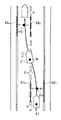
- FIG. 2 shows a scene in which the vehicle V passes through an intersection while driving manually.
- the track calculation unit 24 acquires the positions of the lane dividing lines 41a and 42a detected by the vehicle V in front of the intersection (first point).
- the track calculation unit 24 calculates the central positions of the lane dividing lines 41a and 42a and stores them as the first predetermined position P1. Since the lane dividing line does not exist in the intersection shown in FIG. 2, the vehicle V cannot detect the lane dividing line while the vehicle V enters the intersection and travels on the traveling locus 51a. Then, when the vehicle V passes through the intersection, the vehicle V can detect the lane dividing line again.
- the track calculation unit 24 acquires the positions of the lane dividing lines 43a and 44a detected at the point (second point) where the vehicle V has passed the intersection. Then, the central positions of the lane dividing lines 43a and 44a are calculated and stored as the second predetermined position P2. The track calculation unit 24 calculates and stores the direction D1 along the own lane at the first predetermined position P1 and the direction D2 along the own lane at the second predetermined position P2.
- the track calculation unit 24 states that the direction indicator of the vehicle V is not operating while the vehicle V travels in the section from the first predetermined position P1 to the second predetermined position P2. to decide. Then, the first predetermined position so that the directions match both or one of the direction D1 along the own lane at the first predetermined position P1 and the direction D2 along the own lane at the second predetermined position P2.
- the runway 61a connecting P1 and the second predetermined position P2 is calculated.
- the track storage unit 25 sets the absolute position A1 and the azimuth of the vehicle V at the first point, the positions of the lane dividing lines 41a and 42a, and the first and second predetermined positions P1, P2 and the track 61a. As a set, it is stored in the memory in the controller 20.
- FIG. 3 shows a scene in which the vehicle V turns right at an intersection while driving manually.
- the track calculation unit 24 acquires the positions of the lane dividing lines 41b and 42b detected by the vehicle V in front of the intersection (first point).
- the track calculation unit 24 calculates the central positions of the lane dividing lines 41b and 42b and stores them as the first predetermined position P1. After that, while the vehicle V enters the intersection, travels on the travel locus 51b, and turns right at the intersection, the vehicle V cannot detect the lane dividing line. Then, when the vehicle V turns right at the intersection, the vehicle V can detect the lane dividing line again.
- the track calculation unit 24 acquires the positions of the lane dividing lines 43b and 44b detected at the point (second point) where the vehicle V turns right at the intersection. Then, the central positions of the lane dividing lines 43b and 44b are calculated and stored as the second predetermined position P2. The track calculation unit 24 calculates and stores the direction D1 along the own lane at the first predetermined position and the direction D2 along the own lane at the second predetermined position.
- the track calculation unit 24 states that the turn signal of the vehicle V is operating while the vehicle V travels in the section from the first predetermined position P1 to the second predetermined position P2. to decide. Then, the track calculation unit 24 determines that there is a deviation of the predetermined position or more from the azimuth angle of the vehicle V at each of the first and second predetermined positions P1 and P2 or the first and second points. do. Then, along the direction D1 along the own lane at the first predetermined position P1 connecting the first predetermined position P1 and the second predetermined position P2, and along the own lane at the second predetermined position P2. A smooth curve having the same direction in both or one of the directions D2 is calculated as the runway 61b. The track calculation unit 24 calculates the track 61b from, for example, a clothoid curve or a spline curve.
- the track storage unit 25 sets the absolute positions A1 and azimuth of the vehicle V at the first point, the positions of the lane dividing lines 41b and 42b, and the first and second predetermined positions P1, P2 and the track 61b as a set. Then, it is stored in the memory in the controller 20.
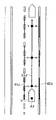
- FIG. 4 shows a scene in which the vehicle V changes lanes during manual driving.
- the track calculation unit 24 acquires the positions of the lane dividing lines 41c and 42c detected at the point (first point) before the vehicle V changes lanes.
- the track calculation unit 24 calculates the central positions of the lane dividing lines 41c and 42c and stores them as the first predetermined position P1.
- the positions of the lane dividing lines 43c and 44c detected at the point (second point) after the vehicle V travels on the traveling locus 51c and starts changing lanes are acquired.
- the central positions of the lane dividing lines 43c and 44c are calculated and stored as the second predetermined position P2.
- the track calculation unit 24 calculates and stores the direction D1 along the own lane at the first predetermined position P1 and the direction D2 along the own lane at the second predetermined position P2.
- the track calculation unit 24 determines that the direction indicator of the vehicle V is operating while the vehicle V travels from the first predetermined position P1 to the second predetermined position P2. Then, the track calculation unit 24 states that there is no deviation of the predetermined position or more from the azimuth angle of the vehicle V at the first and second predetermined positions P1 and P2 or each of the first and second points. to decide. In this case, the track calculation unit 24 ends the process without calculating the track.
- the first and second predetermined positions P1, P2 and the tracks 61a and 61b are described by relative positions in the relative coordinate system with the absolute position A1 of the vehicle V when the vehicle V is at the first point as the origin. Will be done.
- the absolute position estimation unit 23 estimates the absolute position A1 of the vehicle V.
- the relative position estimation unit 22 estimates the relative position R of the vehicle V with the absolute position A1 as the origin.
- the track calculation unit 24 calculates the relative positions of the first and second predetermined positions P1, P2 and the tracks 61a and 61b based on these absolute positions A1 and relative positions R.
- FIG. 5 shows a scene in which the vehicle V is about to travel again at the intersection shown in FIG. 2 that has traveled in the past.
- the track search unit 26 searches the track stored in the track storage unit 25 for the track closest to the absolute position A2 of the vehicle V within a predetermined range from the current absolute position A2 of the vehicle V.
- the track search unit 26 extracts the track 61a, which is within a predetermined range from the current absolute position A2 of the vehicle V and is closest to the absolute position A2 of the vehicle V. Then, the absolute position A1 and the azimuth angle of the vehicle V and the positions of the lane dividing lines 41a and 42a, which are stored as a set with the track 61a, are extracted.
- the track correction unit 27 determines whether or not the current absolute position A2 and azimuth of the vehicle V deviate from the absolute position A1 and the azimuth of the vehicle V extracted by the track search unit 26 by a predetermined value or more. In the scene of FIG. 5, in the track correction unit 27, the current absolute position A2 and azimuth of the vehicle V do not deviate by a predetermined value or more from the absolute position A1 and the azimuth of the vehicle V extracted by the track search unit 26. Judge. Then, the track correction unit 27 acquires the positions of the lane dividing lines 71a and 72a detected by the current vehicle V at the absolute position A2.
- the positions of the lane dividing lines 41a and 42a extracted by the track search unit 26 are associated with the positions of the lane dividing lines 71a and 72a.
- the coordinate transformation (translation / rotation) T is calculated so that the positions of the lane dividing lines 41a and 42a match the positions of the lane dividing lines 71a and 72a as much as possible.
- the track correction unit 27 applies the calculated coordinate conversion T to the track 61a to correct the position of the track 61a to the track 81a relative to the current vehicle V. Then, the corrected track is set as the current track of the vehicle V. In this way, by correcting the position of the track based on a clear target called the lane dividing line, it is possible to suppress the deviation of the track due to the position error of the GNSS.
- the track search method and track correction method have been clarified by taking the case where the vehicle V goes straight at the intersection as an example, but it is also applied when the vehicle V turns right or left at the intersection, or when traveling on a straight road or a curve. , Not limited to this.
- the controller 20 When the vehicle V is traveling on a track connecting a predetermined position of the detected lane dividing line in a section where the vehicle V can continuously detect the lane dividing line of the own lane, the controller 20 is set to the first predetermined position. Instead of the lane connecting to the second predetermined position, the lane of the vehicle V may be accumulated. That is, the position with respect to the lane dividing lines 41d and 42d at the first predetermined position and the second predetermined position may be not the central position of the lane but the relative position of the vehicle V with respect to the lane dividing lines 41d and 42d during manual driving. For example, as shown in FIG.
- the lane accumulating unit 25 is the vehicle at the first point.
- the absolute position A1 and the azimuth angle of V, the positions of the lane dividing lines 41d and 42d detected by the vehicle V at the first point, and the traveling locus 51d are combined and stored in the memory in the controller 20.
- the track correction unit 27 has the positions of the lane dividing lines 41d and 42d stored in combination with the travel track 51d extracted by the track search unit 26, and the current vehicle V.
- the traveling locus 51d extracted by the track searching unit 26 is corrected to the running track 81d relative to the current vehicle V. Then, the corrected track 81d is set as the track of the current vehicle V.
- FIG. 7 shows an example of the operation flow of the travel control device 1 while the vehicle V is in manual operation.
- the absolute position estimation unit 23 estimates the absolute position of the vehicle V on the map based on the self-position of the vehicle V acquired from the GNSS receiver 13 and the vehicle speed and the angular velocity.
- the relative position estimation unit 22 estimates the relative position and azimuth of the vehicle V in the relative coordinate system with the absolute position of the vehicle V estimated by the absolute position estimation unit 23 as the origin by odometry.
- the lane dividing line detection unit 21 detects the lane dividing line in front of the vehicle provided at the widthwise end of the own lane in which the vehicle V is traveling from the image taken by the camera 10. .. Proceeding to step S102, the lane dividing line detection unit 21 determines whether or not the lane dividing line has been successfully detected. If the lane dividing line is successfully detected (YES in step S102), the process proceeds to step S103. On the other hand, when the detection of the lane dividing line fails (NO in step S102), the process of FIG. 7 is terminated.
- step S103 the track calculation unit 24 calculates and stores a predetermined position with respect to the lane division line detected by the lane division line detection unit 21.
- the track calculation unit 24 calculates and stores the direction along the own lane at the calculated predetermined position.
- step S104 the track calculation unit 24 travels the section from the predetermined position (first predetermined position) stored last time by the vehicle V to the predetermined position (second predetermined position) stored this time.
- Check the operating status of the V direction indicator If the direction indicator of the vehicle V is operating while the vehicle V travels in the section from the first predetermined position to the second predetermined position (YES in step S105), the step S105 is performed. Proceed to S106. On the other hand, if the turn signal of the vehicle V is not operating while the vehicle V travels in the section from the first predetermined position to the second predetermined position (NO in step S105), the process proceeds to step S107.
- step S106 the track calculation unit 24 determines whether or not there is a deviation of a predetermined value or more between the azimuth angles of the vehicle V at the first and second predetermined positions or the first and second points respectively. To judge. If there is a deviation of a predetermined value or more between the azimuth angles of the vehicle V at the first and second predetermined positions or at each of the first and second points (YES in step S106), step S107 is performed. move on. On the other hand, when there is no deviation of the predetermined value or more between the azimuth angles of the vehicle V at the first and second predetermined positions or at each of the first and second points (NO in step S106), FIG. The process of 7 is terminated.
- step S107 the track calculation unit 24 calculates the track connecting the stored first and second predetermined positions.
- the point where the lane dividing line cannot be detected from the state where the lane dividing line can be detected becomes the first point
- the predetermined position with respect to the lane dividing line at this first point is the first point. It becomes one predetermined position.
- the point where the lane dividing line can be detected from the state where the lane dividing line cannot be detected becomes the second point, and the predetermined position with respect to the lane dividing line at this second point becomes the second predetermined position.
- the first point is the point where the lane dividing line cannot be detected from the state where the lane dividing line can be detected, and the lane dividing line can be detected from the state where the lane dividing line cannot be detected.
- the second point is the point where it became, but it is not limited to this.
- the point before a predetermined time from the time when the lane dividing line cannot be detected from the state where the lane dividing line can be detected may be set as the first point.
- a point after a predetermined time from the time when the lane dividing line can be detected from the state where the lane dividing line cannot be detected may be set as the second point.
- the track calculation unit 24 has the first and first directions so that the directions along the own lane at the first predetermined position and the directions along the own lane at the second predetermined position are aligned with each other or one of the directions. Calculate the lane connecting the two predetermined positions.
- the track storage unit 25 includes the absolute position and azimuth of the vehicle V at the first point, the position of the lane dividing line detected by the vehicle V at the first point, and the first and first calculated by the track calculation unit 24. The two predetermined positions and the track are combined and stored in the memory in the controller 20.
- FIG. 8 shows an example of the operation flow of the travel control device 1 while the vehicle V is in automatic driving.
- the absolute position estimation unit 23 estimates the absolute position of the vehicle V on the map based on the self-position of the vehicle V acquired from the GNSS receiver 13 and the vehicle speed and the angular velocity.
- the relative position estimation unit 22 estimates the relative position and azimuth of the vehicle V in the relative coordinate system with the absolute position of the vehicle V estimated by the absolute position estimation unit 23 as the origin by odometry.
- step S201 the track search unit 26 searches for a track closest to the absolute position of the vehicle V within a predetermined range from the current absolute position of the vehicle V from the absolute positions stored in the track storage unit 25. Extract. Then, the absolute position and azimuth angle of the vehicle V stored as a set with the searched track and the position of the lane dividing line are extracted.
- the track correction unit 27 determines whether or not the current absolute position and azimuth of the vehicle V deviate from the absolute position and azimuth of the vehicle V extracted by the track search unit 26 by a predetermined value or more. ..
- the track calculation unit 24 is shown in FIG. The process of 8 is completed.
- step S202 if the current absolute position and azimuth of the vehicle V do not deviate from the absolute position and azimuth of the vehicle V extracted by the track search unit 26 by a predetermined value or more (NO in step S202), the process proceeds to step S203.
- step S203 the lane dividing line detection unit 21 detects the lane dividing line in front of the vehicle provided at the widthwise end of the own lane in which the vehicle V is traveling from the image taken by the camera 10. Proceeding to step S204, the lane dividing line detection unit 21 determines whether or not the lane dividing line has been successfully detected. If the lane dividing line is successfully detected (YES in step S204), the process proceeds to step S205. If the detection of the lane dividing line fails (NO in step S204), the process proceeds to step S206.
- step S205 the track correction unit 27 associates the position of the lane division line searched by the track search unit 26 in step S201 with the position of the lane division line detected by the lane division line detection unit 21 in step S203. Then, the coordinate transformation (translation / rotation) T so that the position of the lane dividing line searched by the track search unit 26 in step S201 matches the position of the lane dividing line detected by the lane dividing line detecting unit 21 in step S203 as much as possible. Is calculated. The track correction unit 27 applies the calculated coordinate conversion T to the track searched by the track calculation unit 24 in step S201, and corrects the track to be relative to the current vehicle V. Then, the corrected track is set as the current track of the vehicle V.
- step S206 the vehicle control unit 28 controls the actuator of the vehicle V so that the vehicle V follows the track corrected by the track correction unit 27, and ends the process of FIG.
- the position of the lane dividing line detected by the vehicle V at the first point and the current vehicle Based on the deviation of the position of the lane dividing line detected by V, the mode of correcting the track connecting the first and second predetermined positions to the track relative to the current vehicle V has been described.
- the first target existing around the own vehicle is detected and stored at the first point and the vehicle V travels in the section where the first and second predetermined positions are stored, the first target is stored.
- the second target corresponding to the first target may be detected and stored, and the track may be corrected based on the positional deviation between the first target and the second target.
- the track storage unit 25 has the absolute position and azimuth of the vehicle V at the first point, the position of the first target detected at the first point, and the second calculated by the track calculation unit 24.
- the first and second predetermined positions and the track are combined and stored in the memory in the controller 20.
- the track correction unit 27 corresponds to the position of the first target stored in combination with the track extracted by the track search unit 26 and the first target detected by the current vehicle V.
- the track extracted by the track search unit 26 is corrected to the track relative to the current vehicle V.
- the first and second markings may be any one or a combination of lane markings, stop lines, traffic lights, signs, and road markings.
- the travel control device detects the lane dividing line provided at the widthwise end of the own lane in which the own vehicle is traveling, and based on the detection result of the lane dividing line, itself It is equipped with a controller that controls the running of the vehicle.
- the first predetermined position with respect to the lane dividing line is calculated and stored, and when it becomes possible to detect from the state where the lane dividing line cannot be detected.
- the second predetermined position with respect to the lane dividing line is calculated and stored. Then, when traveling in the section in which the first and second predetermined positions are stored, the own vehicle is controlled so as to travel on the runway connecting the first predetermined position and the second predetermined position.
- the travel control device calculates the center position in the lane width direction in the own lane as the first predetermined position and the second predetermined position with respect to the lane dividing line. Therefore, it is possible to set a runway connecting the center position in the lane width direction in the own lane when the lane dividing line can be detected. As a result, when traveling in a section in which the first and second predetermined positions are stored, the vehicle can travel in the center position of the lane even in a section where the lane dividing line such as an intersection cannot be detected.
- the travel control device calculates and stores directions along the own lane at each of the first and second predetermined positions, and stores the directions along the own lane at the first predetermined position and the second.
- the track connecting the first predetermined position and the second predetermined position is calculated so that the directions match both or one of the directions along the own lane at the predetermined position.
- the travel control device detects and stores the first target existing around the own vehicle when the first predetermined position is calculated and stored, and the first and second predetermined positions are stored.
- the first target and the corresponding second target are detected, and the track is set based on the difference in position between the first target and the second target. to correct. Therefore, it corresponds to the first target detected when calculating the first predetermined position and the second target detected when traveling in the section where the first and second predetermined positions are stored. It is possible to calculate the deviation of the position from the second target. This makes it possible to correct the error between the position of the locator when calculating the first and second predetermined positions and the position of the locator when traveling in the section where the first and second predetermined positions are stored. It is possible to suppress an error in the position of the track connecting the first and second predetermined positions.
- the first and second markings are one or a combination of lane markings, stop lines, traffic lights, signs, and road markings. This makes it possible to select one or a plurality of detectable targets from the targets existing around the vehicle. As a result, the error between the position of the own vehicle when the first predetermined position is calculated and the position of the own vehicle when traveling in the section where the first and second predetermined positions are stored is corrected with higher accuracy. It is possible to suppress an error in the position of the track connecting the first and second predetermined positions.
- the travel control device is the first and the first when the direction indicator of the own vehicle is operating while the own vehicle travels in the section from the first predetermined position to the second predetermined position. If there is a deviation of the predetermined value or more between the postures of the own vehicle at the second predetermined position or the postures of the own vehicle when the first and second predetermined positions are calculated, the track is calculated and the predetermined value or more is calculated. If there is no divergence, the track is not calculated. Therefore, when the first predetermined position and the second predetermined position deviate from each other, such as when the own vehicle turns left or right or when traveling on a curve, or when the first and second predetermined positions are calculated.
- the track connecting the first predetermined position and the second predetermined position is calculated. Then, when the first and second predetermined positions do not deviate, such as when the own vehicle changes lanes, or when the first and second predetermined positions are calculated, the postures of the own vehicle do not deviate. In this case, the track connecting the first predetermined position and the second predetermined position is not calculated. As a result, when the turn signal is operating, the track can be set separately for the case where the own vehicle turns left or right and the case where the vehicle changes lanes, and it is possible to suppress the setting of an erroneous track.
- the travel control device is used when the position and posture of the own vehicle are calculated and stored in the first predetermined position when traveling in a section in which the first and second predetermined positions are stored. If the position and posture of the own vehicle deviate by a predetermined value or more, the calculated runway is not set as the runway of the own vehicle. Therefore, when the own vehicle is traveling in a state of being greatly deviated from the own lane, the track is not set, so that it is possible to suppress the setting of a track with low accuracy.
Landscapes
- Engineering & Computer Science (AREA)
- Automation & Control Theory (AREA)
- Transportation (AREA)
- Mechanical Engineering (AREA)
- Physics & Mathematics (AREA)
- General Physics & Mathematics (AREA)
- Human Computer Interaction (AREA)
- Multimedia (AREA)
- Theoretical Computer Science (AREA)
- Traffic Control Systems (AREA)
- Navigation (AREA)
- Control Of Driving Devices And Active Controlling Of Vehicle (AREA)
Abstract
Description
図1を参照して、本実施形態に係る走行制御方法を実行する走行制御装置の構成例を説明する。図1に示すように、走行制御装置1は、カメラ10と、車速センサ11と、角速度センサ12と、GNSS受信機13と、コントローラ20と、を備える。本実施形態に係る走行制御装置1は、車両Vに搭載され、車両Vの走行を制御する。
図2~4を参照して、走路算出部24の走路算出方法の一例について説明する。
次に、走路探索部26の走路探索方法及び走路補正部27の走路補正方法の一例を、図5を用いて説明する。
以上説明したように、本発明に係る走行制御装置は、自車両が走行している自車線の幅方向端部に設けられた車線区分線を検出し、車線区分線の検出結果に基づいて自車両の走行制御を行うコントローラを備える。車線区分線が検出できている状態から検出できない状態になった時に、車線区分線に対する第一の所定位置を算出して記憶し、車線区分線が検出できない状態から検出できる状態になった時に、車線区分線に対する第二の所定位置を算出して記憶する。そして、第一及び第二の所定位置が記憶されている区間を走行する際には、第一の所定位置と第二の所定位置とを結ぶ走路を走行するように自車両を制御する。
41a~41d、42a~42d、71a、71d、72a、72d 車線区分線
20 コントローラ
P1 第一の所定位置
P2 第二の所定位置
61a、61b 走路
Claims (8)
- 自車両が走行している自車線の幅方向端部に設けられた車線区分線を検出し、前記車線区分線の検出結果に基づいて前記自車両の走行制御を行うコントローラを備える車両の走行制御方法であって、
前記車線区分線が検出できている状態から検出できない状態になった時に、前記車線区分線に対する第一の所定位置を算出して記憶し、
前記車線区分線が検出できない状態から検出できる状態になった時に、前記車線区分線に対する第二の所定位置を算出して記憶し、
前記第一及び第二の所定位置が記憶されている区間を走行する際には、前記第一の所定位置と前記第二の所定位置とを結ぶ走路を走行するように前記自車両を制御する
ことを特徴とする走行制御方法。 - 前記自車線内における車線幅方向中央位置を、前記車線区分線に対する前記第一及び第二の所定位置として算出する
ことを特徴とする請求項1に記載の走行制御方法。 - 前記第一及び第二の所定位置のそれぞれでの前記自車線に沿った方向を算出して記憶し、
前記第一の所定位置での前記自車線に沿った方向と前記第二の所定位置での前記自車線に沿った方向の両方または一方に向きが一致するように、前記第一の所定位置と前記第二の所定位置とを結ぶ走路を算出する
ことを特徴とする請求項1または2に記載の走行制御方法。 - 前記第一の所定位置を算出して記憶した時の前記自車両の周囲に存在する第一の物標を検出して記憶し、
前記第一及び第二の所定位置が記憶されている区間を走行する際に、前記第一の物標と対応する第二の物標を検出し、
前記第一の物標と前記第二の物標との位置のずれに基づいて、前記走路を補正する
ことを特徴とする請求項1~3のいずれかに記載の走行制御方法。 - 前記第一及び第二の物標とは、車線区分線、停止線、信号機、標識、路面標示のいずれか、もしくは複数の組み合わせである
ことを特徴とする請求項4に記載の走行制御方法。 - 前記自車両が前記第一の所定位置から前記第二の所定位置までの区間を走行する間に、前記自車両の方向指示器が作動している場合に、
前記第一及び第二の所定位置、もしくは、前記第一及び第二の所定位置を算出して記憶した時のそれぞれでの前記自車両の姿勢の間に所定値以上の乖離が存在する場合には、前記走路を算出し、
前記所定値以上の乖離が存在しない場合には、前記走路を算出しない
ことを特徴とする請求項3に記載の走行制御方法。 - 前記第一及び第二の所定位置が記憶されている区間を走行する際に、前記自車両の位置及び姿勢が、前記第一の所定位置を算出して記憶した時の前記自車両の位置及び姿勢と所定値以上乖離している場合には、算出された前記走路を前記自車両の走路として設定しない
ことを特徴とする請求項3に記載の走行制御方法。 - 自車両が走行している自車線の幅方向端部に設けられた車線区分線を検出し、前記車線区分線の検出結果に基づいて前記自車両の走行制御を行うコントローラを備える車両の走行制御装置であって、
前記コントローラは、
前記車線区分線が検出できている状態から検出できない状態になった時に、前記車線区分線に対する第一の所定位置を算出して記憶し、
前記車線区分線が検出できない状態から検出できる状態になった時に、前記車線区分線に対する第二の所定位置を算出して記憶し、
前記第一及び第二の所定位置が記憶されている区間を走行する際には、前記第一の所定位置と前記第二の所定位置とを結ぶ走路を走行するように前記自車両を制御する
ことを特徴とする走行制御装置。
Priority Applications (5)
| Application Number | Priority Date | Filing Date | Title |
|---|---|---|---|
| US18/036,208 US11840226B1 (en) | 2020-11-27 | 2020-11-27 | Travel control method and travel control device |
| CN202080107526.3A CN116547730A (zh) | 2020-11-27 | 2020-11-27 | 行驶控制方法及行驶控制装置 |
| EP20963401.3A EP4254381A4 (en) | 2020-11-27 | 2020-11-27 | TRAVEL CONTROL METHOD AND TRAVEL CONTROL DEVICE |
| PCT/IB2020/000979 WO2022112811A1 (ja) | 2020-11-27 | 2020-11-27 | 走行制御方法及び走行制御装置 |
| JP2022564700A JP7422248B2 (ja) | 2020-11-27 | 2020-11-27 | 走行制御方法及び走行制御装置 |
Applications Claiming Priority (1)
| Application Number | Priority Date | Filing Date | Title |
|---|---|---|---|
| PCT/IB2020/000979 WO2022112811A1 (ja) | 2020-11-27 | 2020-11-27 | 走行制御方法及び走行制御装置 |
Publications (1)
| Publication Number | Publication Date |
|---|---|
| WO2022112811A1 true WO2022112811A1 (ja) | 2022-06-02 |
Family
ID=81754117
Family Applications (1)
| Application Number | Title | Priority Date | Filing Date |
|---|---|---|---|
| PCT/IB2020/000979 WO2022112811A1 (ja) | 2020-11-27 | 2020-11-27 | 走行制御方法及び走行制御装置 |
Country Status (5)
| Country | Link |
|---|---|
| US (1) | US11840226B1 (ja) |
| EP (1) | EP4254381A4 (ja) |
| JP (1) | JP7422248B2 (ja) |
| CN (1) | CN116547730A (ja) |
| WO (1) | WO2022112811A1 (ja) |
Citations (4)
| Publication number | Priority date | Publication date | Assignee | Title |
|---|---|---|---|---|
| JP2010271999A (ja) * | 2009-05-22 | 2010-12-02 | Toyota Motor Corp | 運転支援装置 |
| JP2016218539A (ja) * | 2015-05-15 | 2016-12-22 | トヨタ自動車株式会社 | 車両の走路認識装置 |
| JP2016224593A (ja) | 2015-05-28 | 2016-12-28 | アイシン・エィ・ダブリュ株式会社 | 道路形状検出システム、道路形状検出方法及びコンピュータプログラム |
| JP2019012308A (ja) * | 2017-06-29 | 2019-01-24 | 株式会社デンソーテン | 画像処理装置及び画像処理方法 |
Family Cites Families (16)
| Publication number | Priority date | Publication date | Assignee | Title |
|---|---|---|---|---|
| CN101290230B (zh) * | 2008-04-14 | 2011-03-30 | 深圳市凯立德软件技术股份有限公司 | 一种交叉路口的导航方法及使用了此导航方法的导航系统 |
| CN102667888B (zh) * | 2009-11-27 | 2014-12-31 | 丰田自动车株式会社 | 驾驶辅助装置以及驾驶辅助方法 |
| JP5708449B2 (ja) * | 2011-11-08 | 2015-04-30 | アイシン・エィ・ダブリュ株式会社 | レーン案内表示システム、方法およびプログラム |
| JP5924508B2 (ja) * | 2012-07-06 | 2016-05-25 | トヨタ自動車株式会社 | 車両の走行制御装置 |
| US20140267415A1 (en) * | 2013-03-12 | 2014-09-18 | Xueming Tang | Road marking illuminattion system and method |
| JP6197393B2 (ja) * | 2013-06-20 | 2017-09-20 | 株式会社豊田中央研究所 | レーン地図生成装置及びプログラム |
| DE102015211150B4 (de) * | 2015-06-17 | 2023-05-11 | Bayerische Motoren Werke Aktiengesellschaft | Verfahren, Fahrerassistenzsystem und Fahrzeug zum Lernen einer Trajektorie eines Straßenabschnitts |
| CN105787455A (zh) * | 2016-03-01 | 2016-07-20 | 江苏大学 | 一种引入图像虚拟引导线的车道保持控制算法 |
| CN107963077B (zh) * | 2017-10-26 | 2020-02-21 | 东软集团股份有限公司 | 一种车辆通过路口的控制方法、装置及系统 |
| US11181920B2 (en) * | 2018-08-28 | 2021-11-23 | Denso Corporation | Travel assistance method and travel assistance apparatus |
| US10703365B1 (en) * | 2018-12-26 | 2020-07-07 | Automotive Research & Testing Center | Lane tracking method and lane tracking system for an autonomous vehicle |
| CN110954128B (zh) * | 2019-12-03 | 2021-11-16 | 阿波罗智能技术(北京)有限公司 | 检测车道线位置变化的方法、装置、电子设备和存储介质 |
| CN110909711B (zh) * | 2019-12-03 | 2022-08-02 | 阿波罗智能技术(北京)有限公司 | 检测车道线位置变化的方法、装置、电子设备和存储介质 |
| US11560131B2 (en) * | 2020-01-13 | 2023-01-24 | Nio Technology (Anhui) Co., Ltd. | Lane prediction and smoothing for extended motion planning horizon |
| FR3107589B1 (fr) * | 2020-02-21 | 2022-03-18 | Commissariat Energie Atomique | Procédé de détermination de la position et de l’orientation d’un véhicule. |
| JP7191065B2 (ja) * | 2020-07-06 | 2022-12-16 | 本田技研工業株式会社 | 処理装置、処理方法、およびプログラム |
-
2020
- 2020-11-27 EP EP20963401.3A patent/EP4254381A4/en active Pending
- 2020-11-27 WO PCT/IB2020/000979 patent/WO2022112811A1/ja active Application Filing
- 2020-11-27 JP JP2022564700A patent/JP7422248B2/ja active Active
- 2020-11-27 US US18/036,208 patent/US11840226B1/en active Active
- 2020-11-27 CN CN202080107526.3A patent/CN116547730A/zh active Pending
Patent Citations (4)
| Publication number | Priority date | Publication date | Assignee | Title |
|---|---|---|---|---|
| JP2010271999A (ja) * | 2009-05-22 | 2010-12-02 | Toyota Motor Corp | 運転支援装置 |
| JP2016218539A (ja) * | 2015-05-15 | 2016-12-22 | トヨタ自動車株式会社 | 車両の走路認識装置 |
| JP2016224593A (ja) | 2015-05-28 | 2016-12-28 | アイシン・エィ・ダブリュ株式会社 | 道路形状検出システム、道路形状検出方法及びコンピュータプログラム |
| JP2019012308A (ja) * | 2017-06-29 | 2019-01-24 | 株式会社デンソーテン | 画像処理装置及び画像処理方法 |
Non-Patent Citations (1)
| Title |
|---|
| See also references of EP4254381A4 |
Also Published As
| Publication number | Publication date |
|---|---|
| US20230391325A1 (en) | 2023-12-07 |
| US11840226B1 (en) | 2023-12-12 |
| EP4254381A4 (en) | 2024-01-10 |
| JPWO2022112811A1 (ja) | 2022-06-02 |
| JP7422248B2 (ja) | 2024-01-25 |
| EP4254381A1 (en) | 2023-10-04 |
| CN116547730A (zh) | 2023-08-04 |
Similar Documents
| Publication | Publication Date | Title |
|---|---|---|
| JP5747787B2 (ja) | 車線認識装置 | |
| CN111721285B (zh) | 在自动代客泊车系统中用于估计位置的设备及方法 | |
| CN111066071B (zh) | 驾驶辅助车辆的位置误差校正方法及位置误差校正装置 | |
| JP5966747B2 (ja) | 車両走行制御装置及びその方法 | |
| TWI656519B (zh) | 停車導引系統及其方法與自動停車系統 | |
| US11526173B2 (en) | Traveling trajectory correction method, traveling control method, and traveling trajectory correction device | |
| US20170088168A1 (en) | Vehicle steering control apparatus | |
| US10710583B2 (en) | Vehicle control apparatus | |
| JP6040788B2 (ja) | 区画線信頼度判定装置および運転支援制御装置 | |
| JP7037317B2 (ja) | 自車位置検出装置 | |
| CN113359171B (zh) | 基于多传感器融合的定位方法、装置和电子设备 | |
| US11042759B2 (en) | Roadside object recognition apparatus | |
| CN114526747A (zh) | 用于视觉转向的自动化车辆的车道延伸 | |
| JP6943127B2 (ja) | 位置補正方法、車両制御方法及び位置補正装置 | |
| JP2002008199A (ja) | 車線追従走行制御装置 | |
| JP7418196B2 (ja) | 走行軌跡推定方法及び走行軌跡推定装置 | |
| JP6836446B2 (ja) | 車両の走行車線推定装置 | |
| CN113165661A (zh) | 用于确定车辆的修正轨迹的方法和系统 | |
| CN113795726B (zh) | 自身位置修正方法及自身位置修正装置 | |
| WO2022112811A1 (ja) | 走行制御方法及び走行制御装置 | |
| JP7463997B2 (ja) | 車両制御装置、車両制御方法及び車両制御用コンピュータプログラム | |
| JP3797188B2 (ja) | コーナー開始点・道路分岐点検出装置 | |
| US11919567B2 (en) | Automatic steering control apparatus | |
| JP7006797B2 (ja) | 方位検出システム、方位検出方法、及び方位検出プログラム | |
| JP7414683B2 (ja) | 自車位置推定装置及び自車位置推定方法 |
Legal Events
| Date | Code | Title | Description |
|---|---|---|---|
| 121 | Ep: the epo has been informed by wipo that ep was designated in this application |
Ref document number: 20963401 Country of ref document: EP Kind code of ref document: A1 |
|
| ENP | Entry into the national phase |
Ref document number: 2022564700 Country of ref document: JP Kind code of ref document: A |
|
| WWE | Wipo information: entry into national phase |
Ref document number: 202080107526.3 Country of ref document: CN |
|
| NENP | Non-entry into the national phase |
Ref country code: DE |
|
| ENP | Entry into the national phase |
Ref document number: 2020963401 Country of ref document: EP Effective date: 20230627 |