EP4253877B1 - Kühleinheit, steuerungsverfahren und programm - Google Patents
Kühleinheit, steuerungsverfahren und programm Download PDFInfo
- Publication number
- EP4253877B1 EP4253877B1 EP23151111.4A EP23151111A EP4253877B1 EP 4253877 B1 EP4253877 B1 EP 4253877B1 EP 23151111 A EP23151111 A EP 23151111A EP 4253877 B1 EP4253877 B1 EP 4253877B1
- Authority
- EP
- European Patent Office
- Prior art keywords
- water
- heat exchanger
- refrigerant
- circuit
- pressure
- Prior art date
- Legal status (The legal status is an assumption and is not a legal conclusion. Google has not performed a legal analysis and makes no representation as to the accuracy of the status listed.)
- Active
Links
Images


Classifications
-
- F—MECHANICAL ENGINEERING; LIGHTING; HEATING; WEAPONS; BLASTING
- F25—REFRIGERATION OR COOLING; COMBINED HEATING AND REFRIGERATION SYSTEMS; HEAT PUMP SYSTEMS; MANUFACTURE OR STORAGE OF ICE; LIQUEFACTION SOLIDIFICATION OF GASES
- F25B—REFRIGERATION MACHINES, PLANTS OR SYSTEMS; COMBINED HEATING AND REFRIGERATION SYSTEMS; HEAT PUMP SYSTEMS
- F25B49/00—Arrangement or mounting of control or safety devices
- F25B49/02—Arrangement or mounting of control or safety devices for compression type machines, plants or systems
- F25B49/022—Compressor control arrangements
-
- F—MECHANICAL ENGINEERING; LIGHTING; HEATING; WEAPONS; BLASTING
- F25—REFRIGERATION OR COOLING; COMBINED HEATING AND REFRIGERATION SYSTEMS; HEAT PUMP SYSTEMS; MANUFACTURE OR STORAGE OF ICE; LIQUEFACTION SOLIDIFICATION OF GASES
- F25B—REFRIGERATION MACHINES, PLANTS OR SYSTEMS; COMBINED HEATING AND REFRIGERATION SYSTEMS; HEAT PUMP SYSTEMS
- F25B49/00—Arrangement or mounting of control or safety devices
- F25B49/005—Arrangement or mounting of control or safety devices of safety devices
-
- F—MECHANICAL ENGINEERING; LIGHTING; HEATING; WEAPONS; BLASTING
- F25—REFRIGERATION OR COOLING; COMBINED HEATING AND REFRIGERATION SYSTEMS; HEAT PUMP SYSTEMS; MANUFACTURE OR STORAGE OF ICE; LIQUEFACTION SOLIDIFICATION OF GASES
- F25B—REFRIGERATION MACHINES, PLANTS OR SYSTEMS; COMBINED HEATING AND REFRIGERATION SYSTEMS; HEAT PUMP SYSTEMS
- F25B13/00—Compression machines, plants or systems, with reversible cycle
-
- F—MECHANICAL ENGINEERING; LIGHTING; HEATING; WEAPONS; BLASTING
- F25—REFRIGERATION OR COOLING; COMBINED HEATING AND REFRIGERATION SYSTEMS; HEAT PUMP SYSTEMS; MANUFACTURE OR STORAGE OF ICE; LIQUEFACTION SOLIDIFICATION OF GASES
- F25B—REFRIGERATION MACHINES, PLANTS OR SYSTEMS; COMBINED HEATING AND REFRIGERATION SYSTEMS; HEAT PUMP SYSTEMS
- F25B2313/00—Compression machines, plants or systems with reversible cycle not otherwise provided for
- F25B2313/003—Indoor unit with water as a heat sink or heat source
-
- F—MECHANICAL ENGINEERING; LIGHTING; HEATING; WEAPONS; BLASTING
- F25—REFRIGERATION OR COOLING; COMBINED HEATING AND REFRIGERATION SYSTEMS; HEAT PUMP SYSTEMS; MANUFACTURE OR STORAGE OF ICE; LIQUEFACTION SOLIDIFICATION OF GASES
- F25B—REFRIGERATION MACHINES, PLANTS OR SYSTEMS; COMBINED HEATING AND REFRIGERATION SYSTEMS; HEAT PUMP SYSTEMS
- F25B2339/00—Details of evaporators; Details of condensers
- F25B2339/04—Details of condensers
- F25B2339/047—Water-cooled condensers
-
- F—MECHANICAL ENGINEERING; LIGHTING; HEATING; WEAPONS; BLASTING
- F25—REFRIGERATION OR COOLING; COMBINED HEATING AND REFRIGERATION SYSTEMS; HEAT PUMP SYSTEMS; MANUFACTURE OR STORAGE OF ICE; LIQUEFACTION SOLIDIFICATION OF GASES
- F25B—REFRIGERATION MACHINES, PLANTS OR SYSTEMS; COMBINED HEATING AND REFRIGERATION SYSTEMS; HEAT PUMP SYSTEMS
- F25B2500/00—Problems to be solved
- F25B2500/22—Preventing, detecting or repairing leaks of refrigeration fluids
- F25B2500/222—Detecting refrigerant leaks
-
- F—MECHANICAL ENGINEERING; LIGHTING; HEATING; WEAPONS; BLASTING
- F25—REFRIGERATION OR COOLING; COMBINED HEATING AND REFRIGERATION SYSTEMS; HEAT PUMP SYSTEMS; MANUFACTURE OR STORAGE OF ICE; LIQUEFACTION SOLIDIFICATION OF GASES
- F25B—REFRIGERATION MACHINES, PLANTS OR SYSTEMS; COMBINED HEATING AND REFRIGERATION SYSTEMS; HEAT PUMP SYSTEMS
- F25B2700/00—Sensing or detecting of parameters; Sensors therefor
- F25B2700/19—Pressures
- F25B2700/193—Pressures of the compressor
- F25B2700/1931—Discharge pressures
-
- F—MECHANICAL ENGINEERING; LIGHTING; HEATING; WEAPONS; BLASTING
- F25—REFRIGERATION OR COOLING; COMBINED HEATING AND REFRIGERATION SYSTEMS; HEAT PUMP SYSTEMS; MANUFACTURE OR STORAGE OF ICE; LIQUEFACTION SOLIDIFICATION OF GASES
- F25B—REFRIGERATION MACHINES, PLANTS OR SYSTEMS; COMBINED HEATING AND REFRIGERATION SYSTEMS; HEAT PUMP SYSTEMS
- F25B2700/00—Sensing or detecting of parameters; Sensors therefor
- F25B2700/19—Pressures
- F25B2700/193—Pressures of the compressor
- F25B2700/1933—Suction pressures
-
- F—MECHANICAL ENGINEERING; LIGHTING; HEATING; WEAPONS; BLASTING
- F25—REFRIGERATION OR COOLING; COMBINED HEATING AND REFRIGERATION SYSTEMS; HEAT PUMP SYSTEMS; MANUFACTURE OR STORAGE OF ICE; LIQUEFACTION SOLIDIFICATION OF GASES
- F25B—REFRIGERATION MACHINES, PLANTS OR SYSTEMS; COMBINED HEATING AND REFRIGERATION SYSTEMS; HEAT PUMP SYSTEMS
- F25B2700/00—Sensing or detecting of parameters; Sensors therefor
- F25B2700/21—Temperatures
- F25B2700/2116—Temperatures of a condenser
- F25B2700/21161—Temperatures of a condenser of the fluid heated by the condenser
-
- F—MECHANICAL ENGINEERING; LIGHTING; HEATING; WEAPONS; BLASTING
- F25—REFRIGERATION OR COOLING; COMBINED HEATING AND REFRIGERATION SYSTEMS; HEAT PUMP SYSTEMS; MANUFACTURE OR STORAGE OF ICE; LIQUEFACTION SOLIDIFICATION OF GASES
- F25B—REFRIGERATION MACHINES, PLANTS OR SYSTEMS; COMBINED HEATING AND REFRIGERATION SYSTEMS; HEAT PUMP SYSTEMS
- F25B41/00—Fluid-circulation arrangements
- F25B41/30—Expansion means; Dispositions thereof
- F25B41/385—Dispositions with two or more expansion means arranged in parallel on a refrigerant line leading to the same evaporator
-
- F—MECHANICAL ENGINEERING; LIGHTING; HEATING; WEAPONS; BLASTING
- F25—REFRIGERATION OR COOLING; COMBINED HEATING AND REFRIGERATION SYSTEMS; HEAT PUMP SYSTEMS; MANUFACTURE OR STORAGE OF ICE; LIQUEFACTION SOLIDIFICATION OF GASES
- F25B—REFRIGERATION MACHINES, PLANTS OR SYSTEMS; COMBINED HEATING AND REFRIGERATION SYSTEMS; HEAT PUMP SYSTEMS
- F25B41/00—Fluid-circulation arrangements
- F25B41/30—Expansion means; Dispositions thereof
- F25B41/39—Dispositions with two or more expansion means arranged in series, i.e. multi-stage expansion, on a refrigerant line leading to the same evaporator
Definitions
- the present invention relates to a chilling unit, a control method, and a program.
- Patent Document 1 describes a technology of detecting refrigerant leakage when concentration of the refrigerant exceeds a reference value for a certain period of time or longer.
- Document CN203837315 discloses a device as per the preamble of claim 1.
- Patent Document 1 JP 2020-51738 A
- each device connected to the refrigerant circuit including a compressor, an accumulator, a receiver, and valves (e.g., an expansion valve and a four-way valve), in addition to the water heat exchanger, may need to be replaced during repair, and it may cost to repair and take days until restoration. Therefore, an anomaly such as damage to the water heat exchanger is preferably quickly detected such that the damage does not spread.
- the present disclosure has been made in view of such a problem, and provides a chilling unit, a control method, and a program that can quickly detect an anomaly in a water heat exchanger.
- a chilling unit as defined in claim 1 is provided.
- a control method as defined in claim 8 is provided.
- a program as defined in claim 9 is provided.
- a chilling unit, a control method, and a program according to the present disclosure can quickly detect an anomaly in a water heat exchanger.
- FIGS. 1 to 8 a chilling unit according to a first embodiment of the present disclosure will be described with reference to FIGS. 1 to 8 .
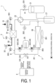
- a chilling unit 1 includes a refrigerant circuit 2, a water circuit 3, and a control device 4.
- the refrigerant circuit 2 includes a compressor 21, a four-way valve 22, a water heat exchanger 23, an expansion valve 24, a receiver 25, an air heat exchanger 26, and an accumulator 27. Each device of the refrigerant circuit 2 is connected by a refrigerant pipe 20.
- the compressor 21 compresses a refrigerant R and supplies the compressed refrigerant R to the refrigerant circuit 2.
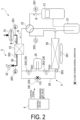
- the four-way valve 22 switches between the cooling operation and the heating operation by switching the flow path of the refrigerant circuit 2. As illustrated in FIG. 1 , the four-way valve 22 feeds, to the air heat exchanger 26, the refrigerant R discharged from the compressor 21 during the cooling operation. Further, as illustrated in FIG. 2 , the four-way valve 22 feeds, to the water heat exchanger 23, the refrigerant R discharged from the compressor 21 during the heating operation.
- the water heat exchanger 23 cools or heats water W by performing heat exchange between the refrigerant R and the water W.
- the expansion valve 24 includes a mechanism for reducing pressure of the refrigerant R when the refrigerant R passes through the expansion valve 24.
- the expansion valve 24 includes a first expansion valve 241, a second expansion valve 242, and a third expansion valve 243.
- the first expansion valve 241 is an expansion valve for the cooling operation.
- the second expansion valve 242 and the third expansion valve 243 are expansion valves for the heating operation.
- the second expansion valve 242 is provided between the water heat exchanger 23 and the receiver 25, and the third expansion valve 243 is provided between the receiver 25 and the air heat exchanger 26.
- the first expansion valve 241 is in an open state, and the second expansion valve 242 and the third expansion valve 243 are in a closed state.
- the first expansion valve 241 is in the closed state, and the second expansion valve 242 and the third expansion valve 243 are in the open state.
- the first expansion valve 241 and the third expansion valve 243 are in a closed state, and the second expansion valve 242 is in an open state.
- the receiver 25 is a container for storing at least some of a liquid refrigerant that passes through the second expansion valve 242 or the third expansion valve 243.
- the air heat exchanger 26 performs heat exchange between the refrigerant R and outside air taken in by a propeller fan 261.
- the accumulator 27 is a device that is provided on an upstream side of the compressor 21 and separates liquid refrigerant and gas refrigerant. Only the gas refrigerant of the refrigerant separated by the accumulator 27 is sent to the compressor 21.
- a plurality of sensors for measuring the pressure and temperature of the refrigerant R are provided in the refrigerant circuit 2.
- a high-pressure-side sensor 201 that measures pressure (HP) of the refrigerant R on a high-pressure side is provided in the refrigerant pipe 20 between the compressor 21 and the four-way valve 22 (on a downstream side of the compressor 21).
- a low-pressure-side sensor 202 that measures pressure (LP) of the refrigerant R on a low-pressure side is provided in the refrigerant pipe 20 between the accumulator 27 and the four-way valve 22 (on an upstream side of the accumulator 27).
- a first temperature sensor 203 that measures a temperature of the refrigerant R is provided in the refrigerant pipe 20 between the expansion valve 24 and the air heat exchanger 26. Measurement values measured by each of the sensors are sequentially transmitted to the control device 4.
- the water circuit 3 includes a water pipe 30, a water pump 31, and a water valve 32.
- the water pipe 30 is inserted through the water heat exchanger 23.
- the water pump 31 is provided closer to an upstream side of the water pipe 30 than the water heat exchanger 23, and sends the water W from the outside to the water pipe 30. While passing through the water heat exchanger 23, the water W sent by the water pump 31 undergoes heat exchange with the refrigerant R so that the temperature of the water W is adjusted.
- the water valve 32 is provided closer to a downstream side of the water pipe 30 than the water heat exchanger 23. When the water valve 32 is opened, the water W after undergoing temperature adjustment is discharged to the outside through the water pipe 30. When the water valve 32 is closed, the discharge of the water W to the outside is stopped.
- a plurality of sensors for measuring the pressure and temperature of the water W are provided in the water circuit 3.
- a first water pressure sensor 301 that measures pressure (WP1) of the water W on an inlet side of the water heat exchanger 23 is provided in the water pipe 30 on an upstream side of the water heat exchanger 23.
- a second water pressure sensor 302 that measures pressure (WP2) of the water W on an outlet side of the water heat exchanger 23 is provided in the water pipe 30 on a downstream side of the water heat exchanger 23.
- a second temperature sensor 303 that measures a temperature of the water W is provided in the water pipe 30 on the downstream side (near the outlet) of the water heat exchanger 23. Measurement values measured by each of the sensors are sequentially transmitted to the control device 4.
- the control device 4 controls the operation of each device of the refrigerant circuit 2 and the water circuit 3, and brings the chilling unit 1 into any state of the cooling operation, the heating operation, and the operation stop.
- the control device 4 detects an anomaly in the water heat exchanger 23 on the basis of a measurement value received from each of the sensors of the refrigerant circuit 2 and the water circuit 3. Further, the control device 4 performs processing of suppressing entry of the water W into the refrigerant circuit 2 when a sign of leakage of the refrigerant R is detected in the water heat exchanger 23. The details of this processing will be described later.
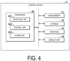
- FIG. 4 is a diagram illustrating a functional configuration of the control device according to the first embodiment of the present disclosure.
- the control device 4 includes a processor 40, a main memory 41, a storage 42, an interface 43, and a display unit 44.
- the processor 40 operates according to a predetermined program to function as a detecting unit 401, a control unit 402, and an alarm unit 403.
- the detecting unit 401 detects an anomaly in the water heat exchanger 23, based on a measurement value of each of the sensors provided in the refrigerant circuit 2 and the water circuit 3. Specifically, the detecting unit 401 detects a low-pressure anomaly in the water heat exchanger 23 when a saturation temperature of the refrigerant R is less than a predetermined saturation temperature lower limit value. The detecting unit 401 further detects presence or absence of a sign of leakage of the refrigerant R from the water heat exchanger 23 during each of the cooling operation, the heating operation, and the operation stop.
- control unit 402 performs various types of processing for suppressing entry of the water W into the refrigerant circuit 2.
- the alarm unit 403 issues an anomaly alarm via the display unit 44.
- the alarm unit 403 may issue an anomaly alarm to an external monitoring device (e.g., a computer, a smartphone, or a tablet) via the interface 43.
- an external monitoring device e.g., a computer, a smartphone, or a tablet
- Commands and data for the processor 40 to operate based on a program are deployed to the main memory 41.
- the storage 42 is a so-called auxiliary storage device, and may be, for example, an electrically erasable programmable read-only memory (EEPROM), a hard disk drive (HDD), or a solid state drive (SSD).
- EEPROM electrically erasable programmable read-only memory
- HDD hard disk drive
- SSD solid state drive
- the interface 43 is an interface (communication interface) for communicably connecting each device and sensor in the refrigerant circuit 2 and the water circuit 3.
- the display unit 44 is a display that displays information such as the presence or absence of an anomaly in the chilling unit 1.
- FIG. 5 is a flowchart illustrating an example of processing of the control device according to the first embodiment of the present disclosure during the cooling operation.
- the control unit 402 controls the operating state of each device of the refrigerant circuit 2 and the water circuit 3 to perform the cooling operation of the chilling unit 1 (step S100). For example, as illustrated in FIG. 1 , the control unit 402 switches the four-way valve 22 such that the refrigerant R discharged by the compressor 21 flows into the air heat exchanger 26, and also brings the first expansion valve 241 into the open state and brings the second expansion valve 242 and the third expansion valve 243 into the closed state. Then, when the compressor 21 is operated, the four-way valve 22 switches to serve as a refrigerant circuit for the cooling operation.
- control unit 402 Before the control unit 402 operates the compressor 21, the control unit 402 operates the water pump 31 in the water circuit 3, and also brings the water valve 32 into the open state if the water valve 32 is installed. In this way, the water W flowing through the water circuit 3 is cooled by the refrigerant R while passing through the water heat exchanger 23.
- the detecting unit 401 constantly monitors a measurement value (pressure LP of the refrigerant R on the low-pressure side) of the low-pressure-side sensor 202 of the refrigerant circuit 2 during the cooling operation to detect presence or absence of a pressure anomaly of the refrigerant.
- a measurement value pressure LP of the refrigerant R on the low-pressure side
- the detecting unit 401 monitors whether a saturation temperature on the low-pressure side (hereinafter also described as an "LP saturation temperature”) is less than a first saturation temperature lower limit value (e.g., -A°C) (step S101).
- LP saturation temperature a saturation temperature on the low-pressure side
- a first saturation temperature lower limit value e.g., -A°C
- a correspondence table of saturation pressure and saturation temperature for each type of the refrigerant R is previously recorded in the storage 42, and the detecting unit 401 determines the LP saturation temperature with reference to the correspondence table. Further, the first saturation temperature lower limit value is preset according to the type of the refrigerant R or the like.
- step S101: NO the detecting unit 401 determines that there is no anomaly in the pressure state of the refrigerant. In this case, the control device 4 continues the cooling operation of the chilling unit 1.
- the detecting unit 401 detects that an anomaly has occurred in low pressure of the refrigerant.
- the control unit 402 stops the cooling operation of the chilling unit 1.
- the alarm unit 403 issues an anomaly alarm indicating an anomaly in the refrigerant circuit 2 (step S102).
- the alarm unit 403 may display a value of the LP saturation temperature or the like together with the anomaly alarm on the display unit 44. Further, the alarm unit 403 may issue the anomaly alarm to an external monitoring terminal or the like via the interface 43.
- an administrator of the chilling unit 1 arranges for repair of the chilling unit 1.
- the detecting unit 401 confirms presence or absence of a sign of leakage of the refrigerant R into the water circuit 3 in the water heat exchanger 23. Specifically, first, the detecting unit 401 determines a subcooling degree at an outlet of the air heat exchanger 26, based on a measurement value of the first temperature sensor 203 immediately before the low-pressure anomaly occurs. Note that, in other embodiments, the first temperature sensor 203 may be a sensor that can measure a subcooling degree, and the detecting unit 401 may acquire the subcooling degree at the outlet of the air heat exchanger 26 from the first temperature sensor 203.
- the detecting unit 401 determines whether the subcooling degree at the outlet of the air heat exchanger 26 is significantly lower than a predetermined subcooling degree reference value, and whether subcooling cannot be guaranteed (step S 103).
- the subcooling degree reference value is preset according to the type of the refrigerant R or the like.
- step S 103 NO
- the detecting unit 401 determines that there is no sign of leakage of the refrigerant R (step S 105). In this case, the control unit 402 terminates the processing while the operation of the chilling unit 1 is stopped.
- the detecting unit 401 further confirms whether a water temperature at the outlet of the water heat exchanger 23 of the water circuit 3 immediately before the low-pressure anomaly occurs is less than a lower limit value (e.g., 3°C) in a water temperature control range (step S 104).
- the lower limit value in the water temperature control range indicates a set temperature in a settable temperature range in the chilling unit 1.
- the lower limit value is “4°C” when the set temperature is “4°C”
- the lower limit value is “7°C” when the set temperature is “7°C”.
- the detecting unit 401 determines that there is no sign of leakage of the refrigerant R (step S 105).
- the low-pressure anomaly of the refrigerant is determined to be due to a cause other than refrigerant leakage from the water heat exchanger 23, for example, clogging of the refrigerant circuit 2.
- the control unit 402 terminates the processing while the operation of the chilling unit 1 is stopped.
- step S104 determines that leakage has already occurred in the water heat exchanger 23, and the refrigerant and water are mixed and the water temperature cannot be controlled.
- the alarm unit 403 issues an anomaly alarm indicating the refrigerant leakage in the water heat exchanger 23 (step S 106).
- an administrator of the chilling unit 1 arranges for repair of the chilling unit 1.
- the refrigerant circuit 2 normally has a pressure higher than that of the water circuit 3.
- the water W of the water circuit 3 may enter the refrigerant circuit 2.
- it may take a long time from when repair is arranged to when repair of the chilling unit 1 is actually performed. Therefore, when the leakage of the refrigerant R is left until the repair of the chilling unit 1 is performed, the water W enters the refrigerant circuit 2, and damage to the chilling unit 1, such as failure of the compressor 21, may spread.
- control unit 402 performs automatic processing of suppressing entry of the water W into the refrigerant circuit 2 when the refrigerant leakage is detected. Details of this processing will be described with reference to FIGS. 5 and 6 .
- FIG. 6 is a diagram illustrating an example of a control state when refrigerant leakage in the chilling unit according to the first embodiment of the present disclosure is detected.
- the control unit 402 performs third processing of stopping the water pump 31 of the water circuit 3 and bringing the water valve 32 into the closed state (step S107). In this way, entry of the water W into the refrigerant circuit 2 can be suppressed. Further, in a system in which a plurality of the chilling units 1 are coupled with one water circuit 3, when the refrigerant R leaks into the water circuit 3 of a certain chilling unit 1, the water W mixed with the refrigerant R can be prevented from circulating in another chilling unit.
- the control unit 402 performs first processing (steps S108 and S109) of increasing pressure in the refrigerant circuit 2 such that the pressure in the refrigerant circuit 2 is not equalized with the pressure in the water circuit 3. Specifically, as illustrated in FIG. 6 , the control unit 402 brings the first expansion valve 241 and the second expansion valve 242 into the closed state, brings the third expansion valve 243 into the open state, and also operates the four-way valve 22 to switch to a heating operation flow path (step S108). Further, the control unit 402 starts up the compressor 21 (step S109).
- control unit 402 sends the refrigerant R compressed by the compressor 21 while limiting the flow path on a downstream side of the compressor 21 to a short section ending at the second expansion valve 242, and thus increases pressure in the section from the compressor 21 to the second expansion valve 242 in the refrigerant circuit 2, that is, a section around the water heat exchanger 23.
- control unit 402 performs second processing (steps S110 to S 112) of maintaining the pressure in the section around the water heat exchanger 23 in the refrigerant circuit 2 within a fixed range.
- the control unit 402 confirms whether the high-pressure-side pressure HP of the refrigerant circuit 2 measured by the high-pressure-side sensor 201 after the compressor 21 starts up exceeds a pressure upper limit value (step S 110).
- the pressure upper limit value is, for example, a value acquired by adding a predetermined margin ⁇ 1 to the inlet-side pressure WP1 of the water circuit 3 measured by the first water pressure sensor 301.
- the value of the margin ⁇ 1 is preset according to the type of the refrigerant R, a characteristic of the compressor 21, or the like.
- step S 110: NO the control unit 402 continues the operation of the compressor 21.
- step S110: YES the control unit 402 stops the compressor 21 (step Sill). In this way, the control unit 402 can suppress an increase more than necessary in the pressure in the section around the water heat exchanger 23 of the refrigerant circuit 2 with respect to the pressure in the water circuit 3.
- the control unit 402 confirms whether the high-pressure-side pressure HP is less than the pressure lower limit value (step S112).
- the pressure upper limit value is, for example, a value acquired by adding a predetermined margin ⁇ 2 to the inlet-side pressure WP1 of the water circuit 3 measured by the first water pressure sensor 301.
- the value of the margin ⁇ 2 is preset according to the type of the refrigerant R, a characteristic of the compressor 21, or the like. Note that the values of the margins ⁇ 1 and ⁇ 2 may be the same, or may be different.
- step S 112 NO
- the control unit 402 causes the compressor 21 to remain stopped.
- step S112 the control unit 402 starts up the compressor 21 (returns to step S109). In this way, the control unit 402 can suppress entry of the water W into the refrigerant circuit 2 because the pressure in the section around the water heat exchanger 23 of the refrigerant circuit 2 is equalized with the pressure in the water circuit 3.
- control unit 402 performs the first to third processing as illustrated in FIG. 5 , and suppresses entry of the water W in the water circuit 3 into the refrigerant circuit 2 to prevent the spread of damage in the chilling unit 1.
- FIG. 7 is a flowchart illustrating an example of processing of the control device according to the first embodiment of the present disclosure during the heating operation.
- the control unit 402 controls the operation state of each device of the refrigerant circuit 2 and the water circuit 3, and performs the heating operation of the chilling unit 1 (step S200). For example, as illustrated in FIG. 2 , the control unit 402 switches the four-way valve 22 such that the refrigerant R discharged by the compressor 21 flows into the water heat exchanger 23, and also brings the first expansion valve 241 into the closed state and brings the second expansion valve 242 and the third expansion valve 243 into the open state. When the control unit 402 switches the refrigerant circuit 2 to a heating operation flow path in such a manner, the control unit 402 operates the compressor 21.
- control unit 402 Before the control unit 402 operates the compressor 21, the control unit 402 operates the water pump 31 in the water circuit 3, and also brings the water valve 32 into the open state if the water valve 32 is installed. In this way, the water W flowing through the water circuit 3 is heated by the refrigerant R while passing through the water heat exchanger 23.
- the detecting unit 401 constantly monitors the pressure LP of the refrigerant R on the low-pressure side during the heating operation to detect presence or absence of an anomaly in the water heat exchanger 23. Specifically, the detecting unit 401 monitors whether an outside temperature is equal to or greater than 0°C and whether the LP saturation temperature is less than a second saturation temperature lower limit value (e.g., -B°C) (step S201).
- a second saturation temperature lower limit value is preset according to the type of the refrigerant R or the like.
- step S201: NO the detecting unit 401 determines that there is no anomaly (no leakage) in the refrigerant circuit 2. In this case, the control device 4 continues the heating operation of the chilling unit 1.
- the detecting unit 401 detects that leakage from the refrigerant circuit 2 may occur and there may be a sign of leakage of the refrigerant R in the water heat exchanger 23.
- the control unit 402 stops the heating operation of the chilling unit 1.
- the alarm unit 403 issues an anomaly alarm indicating the sign of refrigerant leakage in the water heat exchanger 23 (step S202).
- control unit 402 When the sign of refrigerant leakage is detected, the control unit 402 performs processing of suppressing entry of the water W into the refrigerant circuit 2 similarly to the cooling operation.
- control unit 402 performs third processing of stopping the water pump 31 of the water circuit 3 and bringing the water valve 32 into the closed state (step S203). This processing is the same as that in step S107 in FIG. 5 .
- the control unit 402 performs first processing (steps S204 and S205) of increasing pressure in the refrigerant circuit 2 such that the pressure in the refrigerant circuit 2 is not equalized with pressure in the water circuit 3.
- the flow path may switch to the flow path during the operation stop illustrated in FIG. 3 .
- the control unit 402 brings the first expansion valve 241 and the second expansion valve 242 into the closed state, brings the third expansion valve 243 into the open state, and also operates the four-way valve 22 to switch to the heating operation flow path (step S204).
- control unit 402 starts up the compressor 21 (step S205), and increases pressure in the section from the compressor 21 to the second expansion valve 242 in the refrigerant circuit 2, that is, the section around the water heat exchanger 23.
- This processing is the same as that in steps S108 to S109 in FIG. 5 .
- control unit 402 performs second processing (steps S206 to S208) of maintaining the pressure in the section around the water heat exchanger 23 of the refrigerant circuit 2 within a fixed range. This processing is the same as that in steps S110 to S112 in FIG. 5 .
- control unit 402 When a sign of leakage of the refrigerant R is detected during the heating operation, the control unit 402 performs the first to third processing as illustrated in FIG. 7 , and suppresses a decrease in the pressure in the refrigerant circuit 2 and entry of the water W in the water circuit 3 into the refrigerant circuit 2.
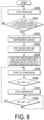
- FIG. 8 is a flowchart illustrating an example of processing of the control device according to the first embodiment of the present disclosure during the operation stop.
- the control unit 402 brings the chilling unit 1 into a state of operation stop according to an operation by an administrator or the like of the chilling unit 1 (step S300). At this time, as illustrated in FIG. 3 , the control unit 402 brings the first expansion valve 241 and the third expansion valve 243 into the closed state and brings the second expansion valve 242 into the open state to stop the compressor 21. Further, the control unit 402 stops the water pump 31 and brings the water valve 32 into the closed state. Note that, in other embodiments, for protection control, the control unit 402 may operate the water pump 31 and bring the water valve 32 into the open state even during the operation stop.
- the detecting unit 401 constantly monitors the low-pressure-side pressure LP or the high-pressure-side pressure HP of the refrigerant R during the operation stop to detect presence or absence of an anomaly in the water heat exchanger 23. Specifically, the detecting unit 401 monitors whether an outside temperature is equal to or greater than 0°C and whether the LP saturation temperature or a saturation temperature on the high-pressure side (hereinafter also described as an "HP saturation temperature") is less than a third saturation temperature lower limit value (e.g., -C°C) (step S301).
- the third saturation temperature lower limit value is preset according to the type of the refrigerant R or the like.
- the detecting unit 401 determines that there is no problem in the refrigerant circuit 2 and there is no anomaly in the water heat exchanger 23. In this case, the control device 4 causes the chilling unit 1 to remain in the state of the operation stop.
- the detecting unit 401 detects that leakage from the refrigerant circuit 2 may occur and there may be a sign of leakage of the refrigerant R in the water heat exchanger 23. In this case, the alarm unit 403 issues an anomaly alarm indicating a sign of the refrigerant leakage from the refrigerant circuit 2 (step S302).
- control unit 402 When the sign of refrigerant leakage is detected, the control unit 402 performs processing of suppressing entry of the water W into the refrigerant circuit 2 similarly to the cooling operation.
- step S303 In a case of operation of operating the water pump 31 even during the operation stop, the control unit 402 performs third processing of stopping the water pump 31 of the water circuit 3, and also bringing the water valve 32 into the closed state (step S303). This processing is the same as that in step S107 in FIG. 5 . Note that, in a case of an operation of stopping the water pump 31 during the operation stop, step S303 may be omitted.
- the control unit 402 performs first processing (steps S304 and S305) of increasing pressure in the refrigerant circuit 2 such that the pressure in the refrigerant circuit 2 is not equalized with pressure in the water circuit 3. This processing is the same as that in steps S108 to S109 in FIG. 5 .
- control unit 402 performs second processing (steps S306 to S308) of maintaining the pressure in the section around the water heat exchanger 23 of the refrigerant circuit 2 within a fixed range. This processing is the same as that in steps S110 to S112 in FIG. 5 .
- control unit 402 When a sign of leakage of the refrigerant R is detected during the operation stop, the control unit 402 performs the first to third processing as illustrated in FIG. 8 , and suppresses a decrease in the pressure in the refrigerant circuit 2 and entry of the water W in the water circuit 3 into the refrigerant circuit 2.
- step S301 in FIG. 8 when the outside temperature is equal to or greater than 0°C, and the LP saturation temperature or the HP saturation temperature is less than the third saturation temperature lower limit value (when a first condition is satisfied), the detecting unit 401 according to the present embodiment detects that a sign of leakage of the refrigerant R has occurred, and, in steps S303 to S308, the detecting unit 401 assumes leakage from the water heat exchanger 23 and performs maintenance control, which is not limited thereto.
- the detecting unit 401 may detect that a sign of leakage of the refrigerant R has occurred in the water heat exchanger 23.
- a case in which the second condition is satisfied is, for example, a case in which the outside temperature is equal to or greater than 0°C and a difference between the LP saturation temperature (or the HP saturation temperature) and the outside temperature is equal to or greater than a predetermined temperature differential (e.g., 10 degrees), and a change in the LP saturation temperature (or the HP saturation temperature) does not follow a temperature change of the outside temperature.
- the detecting unit 401 can detect the refrigerant leakage of the refrigerant R by confirming whether the second condition is satisfied.
- FIGS. 5 , 7 , and 8 illustrate an example in which the control unit 402 performs the first processing (steps S108 and S109, S204 and S205, and S304 and S305) after the third processing (steps S 107, S203, and S303), but the order of the processing is not limited thereto.
- the control unit 402 may perform the third processing after the first processing or simultaneously with the first processing.
- the control device 4 includes the detecting unit 401 configured to detect an anomaly in the water heat exchanger 23 when an LP saturation temperature or an HP saturation temperature of the refrigerant circuit 2 is less than a predetermined saturation temperature lower limit value.
- the chilling unit 1 can quickly detect an anomaly in the water heat exchanger 23.
- the detecting unit 401 of the control device 4 detects an anomaly indicating refrigerant leakage in the water heat exchanger 23 when, during a cooling operation, the LP saturation temperature of the refrigerant circuit 2 is less than a first saturation temperature lower limit value, a subcooling degree at an outlet of the air heat exchanger 26 is lower than a subcooling degree reference value, and a water temperature at an outlet of the water heat exchanger 23 of the water circuit 3 is equal to or greater than a lower limit value in a water temperature control range.
- the chilling unit 1 can quickly detect refrigerant leakage during the cooling operation.
- the detecting unit 401 of the control device 4 detects an anomaly indicating a sign of refrigerant leakage in the water heat exchanger 23 when the LP saturation temperature of the refrigerant circuit 2 is less than a second saturation temperature lower limit value during a heating operation.
- the chilling unit 1 can quickly detect a sign of refrigerant leakage during the heating operation.
- the detecting unit 401 of the control device 4 detects an anomaly indicating a sign of refrigerant leakage in the water heat exchanger 23 when the LP saturation temperature or the HP saturation temperature of the refrigerant circuit 2 is less than a third saturation temperature lower limit value during an operation stop.
- the chilling unit 1 can quickly detect a sign of refrigerant leakage during the operation stop.
- control device 4 further includes the control unit 402 that performs first processing of closing the first expansion valve 241 and the second expansion valve 242, switching the four-way valve 22 so as to set the heating operation flow path, and starting up the compressor 21 when a sign of the refrigerant leakage is detected.
- the chilling unit 1 can maintain a state where the refrigerant circuit 2 has pressure greater than that of the water circuit 3, and can suppress entry of the water W into the refrigerant circuit 2. In this way, the likelihood of each device connected to the refrigerant circuit 2 being damaged by the water that enters the refrigerant circuit 2 can be reduced.
- control unit 402 of the control device 4 further performs second processing of, after the first processing is performed, stopping the compressor 21 when the high-pressure-side pressure HP of the refrigerant circuit 2 is equal to or greater than a pressure upper limit value, and starting up the compressor 21 when the high-pressure-side pressure HP of the refrigerant circuit 2 is less than a pressure lower limit value.
- the chilling unit 1 can maintain pressure in the section around the water heat exchanger 23 of the refrigerant circuit 2 within a fixed range. In this way, entry of the water W from the water circuit 3 into the refrigerant circuit 2 can be suppressed.
- control unit 402 of the control device 4 sets, as the pressure lower limit value, a value acquired by adding the predetermined margin ⁇ 2 to the inlet-side pressure WP1 of the water circuit 3.
- the chilling unit 1 can maintain pressure in the section around the water heat exchanger 23 of the refrigerant circuit 2 in a state of being higher than pressure in the water circuit 3. In this way, entry of the water W from the water circuit 3 into the refrigerant circuit 2 can be more reliably suppressed.
- control unit 402 of the control device 4 further performs third processing of stopping the water pump 31 and closing the water valve 32 when a sign of the refrigerant leakage is detected.
- the chilling unit, the control method, and the program described in the embodiment above are understood as follows, for example.
Landscapes
- Engineering & Computer Science (AREA)
- Physics & Mathematics (AREA)
- Mechanical Engineering (AREA)
- Thermal Sciences (AREA)
- General Engineering & Computer Science (AREA)
- Air Conditioning Control Device (AREA)
- Compression-Type Refrigeration Machines With Reversible Cycles (AREA)
Claims (9)
- Kühleinheit (1), umfassend:einen Kältemittelkreislauf (2), der einen Verdichter (21), der konfiguriert ist, um ein Kältemittel zu verdichten, einen Luftwärmetauscher (26), der konfiguriert ist, um einen Wärmeaustausch zwischen dem Kältemittel und der Außenluft durchzuführen, einen Wasserwärmetauscher (23), der konfiguriert ist, um einen Wärmeaustausch zwischen dem Kältemittel und dem Wasser durchzuführen, ein Expansionsventil (24), das zwischen dem Luftwärmetauscher (26) und dem Wasserwärmetauscher (23) bereitgestellt ist, und ein Vierwegeventil (22), das konfiguriert ist, um einen Strömungsweg des Kältemittels auf einen Kühlbetriebsströmungsweg oder einen Heizbetriebsströmungsweg umzuschalten, beinhaltet;einen Wasserkreislauf (3), der eine Wasserleitung (30), die durch den Wasserwärmetauscher (23) eingeführt ist, eine Wasserpumpe (31), die konfiguriert ist, um das Wasser zu der Wasserleitung (30) zu leiten, und ein Wasserventil (32), das näher auf einer stromabwärtigen Seite der Wasserleitung (30) als der Wasserwärmetauscher (23) bereitgestellt ist; undeine Steuervorrichtung (4), die konfiguriert ist, um den Kältemittelkreislauf (2) und den Wasserkreislauf (3) zu steuern,dadurch gekennzeichnet, dass die Steuervorrichtung (4) eine Erfassungseinheit (401) beinhaltet, die konfiguriert ist, um eine Anomalie in dem Wasserwärmetauscher (23) zu erfassen, wenn eine Sättigungstemperatur des Kältemittelkreislaufs (2) auf einer Niederdruckseite oder einer Hochdruckseite niedriger ist als ein vorbestimmter unterer Sättigungstemperatur-Grenzwert,wobei die Erfassungseinheit (401) der Steuervorrichtung (4) konfiguriert ist, um eine Anomalie zu erfassen, die eine Kältemittelleckage in dem Wasserwärmetauscher (23) angibt, wenn während eines Kühlbetriebs eine Sättigungstemperatur des Kältemittelkreislaufs (2) auf einer Niederdruckseite niedriger ist als ein erster unterer Sättigungstemperatur-Grenzwert, ein Unterkühlungsgrad an einem Auslass des Luftwärmetauschers (26) niedriger ist als ein Unterkühlungsgrad-Referenzwert, und eine Wassertemperatur an einem Auslass des Wasserwärmetauschers (23) in dem Wasserkreislauf (3) gleich wie oder größer als ein unterer Grenzwert in einem Wassertemperatursteuerbereich ist.
- Kühleinheit (1) nach Anspruch 1, wobei
die Erfassungseinheit (401) der Steuervorrichtung (4) konfiguriert ist, um eine Anomalie zu erfassen, die ein Anzeichen für eine Kältemittelleckage in dem Wasserwärmetauscher (23) angibt, wenn eine Sättigungstemperatur des Kältemittelkreislaufs (2) auf einer Niederdruckseite während eines Heizbetriebs niedriger ist ein zweiter unterer Sättigungstemperatur-Grenzwert. - Kühleinheit (1) nach einem der Ansprüche 1 oder 2, wobei
die Erfassungseinheit (401) der Steuervorrichtung (4) konfiguriert ist, um eine Anomalie zu erfassen, die ein Anzeichen für eine Kältemittelleckage in dem Wasserwärmetauscher (23) angibt, wenn eine Sättigungstemperatur des Kältemittelkreislaufs (2) auf einer Niederdruckseite oder einer Hochdruckseite während eines Betriebshalts niedriger ist ein dritter unterer Sättigungstemperatur-Grenzwert. - Kühleinheit (1) nach einem der Ansprüche 2 oder 3, wobei
die Steuervorrichtung (4) ferner eine Steuereinheit (402) enthält, die konfiguriert ist, um, wenn ein Anzeichen für die Kältemittelleckage erfasst wird, eine erste Verarbeitung eines Schließens des Expansionsventils (24), des Umschaltens des Vierwegeventils (22), um den Heizbetriebsströmungswegs einzustellen, und eines Startens des Verdichters (21) durchzuführen. - Kühleinheit (1) nach Anspruch 4, wobei
die Steuereinheit (402) der Steuervorrichtung (4) konfiguriert ist, um nach dem Durchführen der ersten Verarbeitung eine zweite Verarbeitung durchzuführen, bei der sie den Verdichter (21) anhält, wenn ein Druck in dem Kältemittelkreislauf (2) auf einer Hochdruckseite gleich wie oder größer als ein oberer Druckgrenzwert ist, und den Verdichter (21) startet, wenn der Druck in dem Kältemittelkreislauf (2) auf einer Hochdruckseite niedriger ist als ein unterer Druckgrenzwert. - Kühleinheit (1) nach Anspruch 5, wobei
die Steuereinheit (402) der Steuervorrichtung (2) konfiguriert ist, um als unteren Druckgrenzwert einen Wert festzulegen, der durch Addieren einer vorbestimmten Spanne zu einem Messwert von Drucks in dem Wasserkreislauf (3) auf einer Einlassseite ermittelt wird. - Kühleinheit (1) nach einem der Ansprüche 5 oder 6, wobei
die Steuereinheit (402) der Steuervorrichtung (4) konfiguriert ist, um, wenn ein Anzeichen für die Kältemittelleckage erkannt wird, ferner eine dritte Verarbeitung eines Anhaltens der Wasserpumpe (31) und eines Schließens der Wasserventil (32) durchzuführen. - Verfahren zum Steuern einer Kühleinheit (1), das Folgendes beinhalteteinen Kältemittelkreislauf (2), der einen Verdichter (21), der konfiguriert ist, um ein Kältemittel zu verdichten, einen Luftwärmetauscher (26), der konfiguriert ist, um einen Wärmeaustausch zwischen dem Kältemittel und der Außenluft durchzuführen, einen Wasserwärmetauscher (23), der konfiguriert ist, um einen Wärmeaustausch zwischen dem Kältemittel und dem Wasser durchzuführen, ein Expansionsventil (24), das zwischen dem Luftwärmetauscher und dem Wasserwärmetauscher bereitgestellt ist, und ein Vierwegeventil (22), das konfiguriert ist, um einen Strömungsweg des Kältemittels auf einen Kühlbetriebsströmungsweg oder einen Heizbetriebsströmungsweg umzuschalten, beinhaltet,einen Wasserkreislauf (3), der eine Wasserleitung (30), die durch den Wasserwärmetauscher (23) eingeführt ist, eine Wasserpumpe (31), die konfiguriert ist, um das Wasser zu der Wasserleitung (30) zu leiten, und ein Wasserventil (32), das näher auf einer stromabwärtigen Seite der Wasserleitung (30) als der Wasserwärmetauscher (23) bereitgestellt ist, undeine Steuervorrichtung (4), die konfiguriert ist, um den Kältemittelkreislauf (2) und den Wasserkreislauf (3) zu steuern,wobei das Steuerverfahren dadurch gekennzeichnet ist, dass es ein Erfassen einer Anomalie in dem Wasserwärmetauscher (23) durch die Steuervorrichtung (4) umfasst, wenn eine Sättigungstemperatur des Kältemittelkreislaufs (2) auf einer Niederdruckseite oder einer Hochdruckseite niedriger ist als ein vorbestimmter unterer Sättigungstemperatur-Grenzwert, wobeiin dem Schritt eines Erfassens einer Anomalie eine Anomalie erfasst wird, die eine Kältemittelleckage in dem Wasserwärmetauscher (23) angibt, wenn während eines Kühlbetriebs eine Sättigungstemperatur des Kältemittelkreislaufs (2) auf einer Niederdruckseite niedriger ist als ein erster unterer Sättigungstemperatur-Grenzwert, ein Unterkühlungsgrad an einem Auslass des Luftwärmetauschers (26) niedriger ist als ein Unterkühlungsgrad-Referenzwert, und eine Wassertemperatur an einem Auslass des Wasserwärmetauschers (23) in dem Wasserkreislauf (3) gleich wie oder größer als ein unterer Grenzwert in einem Wassertemperatursteuerbereich ist.
- Computerprogramm, das eine Steuervorrichtung einer Kühleinheit (1), die einen Kältemittelkreislauf (2), der einen Verdichter (21), der konfiguriert ist, um ein Kältemittel zu verdichten, einen Luftwärmetauscher (26), der konfiguriert ist, um einen Wärmeaustausch zwischen dem Kältemittel und der Außenluft durchzuführen, einen Wasserwärmetauscher (23), der konfiguriert ist, um einen Wärmeaustausch zwischen dem Kältemittel und dem Wasser durchzuführen, ein Expansionsventil (24), das zwischen dem Luftwärmetauscher (26) und dem Wasserwärmetauscher (23) bereitgestellt ist, und ein Vierwegeventil (22), das konfiguriert ist, um einen Strömungsweg des Kältemittels auf einen Kühlbetriebsströmungsweg oder einen Heizbetriebsströmungsweg umzuschalten, beinhaltet, undeinen Wasserkreislauf (3), der eine Wasserleitung (30), die durch den Wasserwärmetauscher (23) eingeführt ist, eine Wasserpumpe (31), die konfiguriert ist, um das Wasser zu der Wasserleitung (30) zu leiten, und ein Wasserventil (32), das näher auf einer stromabwärtigen Seite der Wasserleitung (30) als der Wasserwärmetauscher (23) bereitgestellt ist,veranlasst, Schritte auszuführen, die durch die folgenden Schritte gekennzeichnet sind:Ausführen eines Erfassens einer Anomalie in dem Wasserwärmetauscher (23), wenn eine Sättigungstemperatur des Kältemittelkreislaufs (2) auf einer Niederdruckseite oder einer Hochdruckseite niedriger ist als ein vorbestimmter unterer Sättigungstemperatur-Grenzwert,wobei in dem Schritt eines Erfassens einer Anomalie eine Anomalie erfasst wird, die eine Kältemittelleckage in dem Wasserwärmetauscher (23) angibt, wenn während eines Kühlbetriebs eine Sättigungstemperatur des Kältemittelkreislaufs (2) auf einer Niederdruckseite niedriger ist als ein erster unterer Sättigungstemperatur-Grenzwert, ein Unterkühlungsgrad an einem Auslass des Luftwärmetauschers (26) niedriger ist als ein Unterkühlungsgrad-Referenzwert, und eine Wassertemperatur an einem Auslass des Wasserwärmetauschers (23) in dem Wasserkreislauf (3) gleich wie oder größer als ein unterer Grenzwert in einem Wassertemperatursteuerbereich ist.
Applications Claiming Priority (1)
| Application Number | Priority Date | Filing Date | Title |
|---|---|---|---|
| JP2022046288A JP2023140445A (ja) | 2022-03-23 | 2022-03-23 | チリングユニット、制御方法、及びプログラム |
Publications (3)
| Publication Number | Publication Date |
|---|---|
| EP4253877A1 EP4253877A1 (de) | 2023-10-04 |
| EP4253877B1 true EP4253877B1 (de) | 2024-10-23 |
| EP4253877C0 EP4253877C0 (de) | 2024-10-23 |
Family
ID=84923179
Family Applications (1)
| Application Number | Title | Priority Date | Filing Date |
|---|---|---|---|
| EP23151111.4A Active EP4253877B1 (de) | 2022-03-23 | 2023-01-11 | Kühleinheit, steuerungsverfahren und programm |
Country Status (3)
| Country | Link |
|---|---|
| EP (1) | EP4253877B1 (de) |
| JP (1) | JP2023140445A (de) |
| KR (1) | KR102878609B1 (de) |
Families Citing this family (1)
| Publication number | Priority date | Publication date | Assignee | Title |
|---|---|---|---|---|
| KR102716819B1 (ko) * | 2024-02-27 | 2024-10-15 | 한화시스템 주식회사 | 안테나 냉각장치의 냉매 누설 확인 장치 및 그 방법 |
Family Cites Families (13)
| Publication number | Priority date | Publication date | Assignee | Title |
|---|---|---|---|---|
| JPH07294073A (ja) * | 1994-04-19 | 1995-11-10 | Hoshizaki Electric Co Ltd | 冷凍装置 |
| US6430944B1 (en) * | 2001-04-13 | 2002-08-13 | Smc Kabushiki Kaisha | Remote maintenance system and method for chiller units |
| JP4678310B2 (ja) * | 2006-02-15 | 2011-04-27 | 株式会社島津製作所 | 冷却液循環装置 |
| JP5717584B2 (ja) * | 2011-08-10 | 2015-05-13 | 三菱電機株式会社 | 冷凍サイクル装置 |
| JP6086213B2 (ja) * | 2013-01-30 | 2017-03-01 | 三浦工業株式会社 | 冷凍機を用いたチラー |
| JP6310054B2 (ja) * | 2014-02-18 | 2018-04-11 | 東芝キヤリア株式会社 | 冷凍サイクル装置 |
| CN203837315U (zh) * | 2014-04-17 | 2014-09-17 | 广东美的暖通设备有限公司 | 风冷热泵冷热水机组 |
| US10161661B2 (en) * | 2014-11-04 | 2018-12-25 | Mitsubishi Electric Corporation | Refrigeration cycle apparatus, and abnormality detection system for refrigeration cycle apparatus |
| JP6289403B2 (ja) * | 2015-03-04 | 2018-03-07 | 株式会社ヴァレオジャパン | 冷媒不足判定装置、これを備えた冷凍サイクル、及び冷凍サイクルの冷媒不足判定方法 |
| JP6935720B2 (ja) * | 2017-10-12 | 2021-09-15 | ダイキン工業株式会社 | 冷凍装置 |
| JP2020051738A (ja) | 2018-09-28 | 2020-04-02 | ダイキン工業株式会社 | 熱負荷処理システム |
| CN115698606B (zh) * | 2020-06-09 | 2024-03-19 | 三菱电机楼宇解决方案株式会社 | 制冷循环装置 |
| JP7457888B2 (ja) * | 2020-07-02 | 2024-03-29 | パナソニックIpマネジメント株式会社 | 熱媒体循環システム |
-
2022
- 2022-03-23 JP JP2022046288A patent/JP2023140445A/ja active Pending
-
2023
- 2023-01-11 EP EP23151111.4A patent/EP4253877B1/de active Active
- 2023-01-11 KR KR1020230004172A patent/KR102878609B1/ko active Active
Also Published As
| Publication number | Publication date |
|---|---|
| JP2023140445A (ja) | 2023-10-05 |
| EP4253877A1 (de) | 2023-10-04 |
| KR20230138390A (ko) | 2023-10-05 |
| EP4253877C0 (de) | 2024-10-23 |
| KR102878609B1 (ko) | 2025-10-30 |
Similar Documents
| Publication | Publication Date | Title |
|---|---|---|
| JP5517789B2 (ja) | 空気調和機 | |
| EP3486584B1 (de) | Kühlsystem | |
| US20050126190A1 (en) | Loss of refrigerant charge and expansion valve malfunction detection | |
| CN102538300B (zh) | 风冷热泵机组、板式换热器的防冻方法 | |
| WO2000036347A1 (en) | Refrigerator | |
| CN106642450A (zh) | 多联机冷媒平衡系统及多联机空调 | |
| US20220228767A1 (en) | Air Conditioner, Control Method and Control Device Thereof | |
| CN103791594B (zh) | 热泵空调系统及防止系统内漏的控制方法 | |
| EP4253877B1 (de) | Kühleinheit, steuerungsverfahren und programm | |
| WO2020062597A1 (zh) | 温度调节设备的制冷剂含量检测方法、装置、系统和空调 | |
| CN109612015B (zh) | 用于空调的控制保护方法及空调 | |
| CN114294784A (zh) | 一种热泵机组除霜控制方法及热泵机组 | |
| EP4148330B1 (de) | Zirkulationssystem für ein heizmedium | |
| CN107421059A (zh) | 防止可燃性冷媒在空调器关机时进入室内侧的控制方法 | |
| CN119103603A (zh) | 暖通系统 | |
| CN102235722B (zh) | 多联式空调机组回收冷媒时的防爆控制方法 | |
| EP4513096B1 (de) | Wärmepumpensystem und verfahren zur steuerung der pumpengeschwindigkeit auf basis von leckagedetektionsdaten und wasserdurchflussratendaten | |
| CN218884341U (zh) | 一种空调系统 | |
| JP4436727B2 (ja) | エンジン駆動式空気調和装置及びその制御方法 | |
| CN102865645B (zh) | 高温气冷型冷气机及其运转控制方法 | |
| EP4339527A1 (de) | Inspektionsvorrichtung und inspektionsverfahren | |
| CN117053345B (zh) | 带水力模块的多联机的冷媒泄漏控制方法及多联机 | |
| CN121701439A (zh) | 悬浮式压缩机启动保护控制方法 | |
| CN120368431A (zh) | 冷媒泄露的控制方法、装置及空调机组 | |
| JPH0552445A (ja) | エンジン駆動ヒートポンプにおける低圧監視制御 |
Legal Events
| Date | Code | Title | Description |
|---|---|---|---|
| PUAI | Public reference made under article 153(3) epc to a published international application that has entered the european phase |
Free format text: ORIGINAL CODE: 0009012 |
|
| STAA | Information on the status of an ep patent application or granted ep patent |
Free format text: STATUS: THE APPLICATION HAS BEEN PUBLISHED |
|
| AK | Designated contracting states |
Kind code of ref document: A1 Designated state(s): AL AT BE BG CH CY CZ DE DK EE ES FI FR GB GR HR HU IE IS IT LI LT LU LV MC ME MK MT NL NO PL PT RO RS SE SI SK SM TR |
|
| STAA | Information on the status of an ep patent application or granted ep patent |
Free format text: STATUS: REQUEST FOR EXAMINATION WAS MADE |
|
| 17P | Request for examination filed |
Effective date: 20240328 |
|
| RBV | Designated contracting states (corrected) |
Designated state(s): AL AT BE BG CH CY CZ DE DK EE ES FI FR GB GR HR HU IE IS IT LI LT LU LV MC ME MK MT NL NO PL PT RO RS SE SI SK SM TR |
|
| RIC1 | Information provided on ipc code assigned before grant |
Ipc: F25B 49/02 20060101ALI20240419BHEP Ipc: F25B 49/00 20060101AFI20240419BHEP |
|
| GRAP | Despatch of communication of intention to grant a patent |
Free format text: ORIGINAL CODE: EPIDOSNIGR1 |
|
| STAA | Information on the status of an ep patent application or granted ep patent |
Free format text: STATUS: GRANT OF PATENT IS INTENDED |
|
| INTG | Intention to grant announced |
Effective date: 20240604 |
|
| RAP3 | Party data changed (applicant data changed or rights of an application transferred) |
Owner name: MITSUBISHI HEAVY INDUSTRIES THERMAL SYSTEMS, LTD. |
|
| GRAS | Grant fee paid |
Free format text: ORIGINAL CODE: EPIDOSNIGR3 |
|
| GRAA | (expected) grant |
Free format text: ORIGINAL CODE: 0009210 |
|
| STAA | Information on the status of an ep patent application or granted ep patent |
Free format text: STATUS: THE PATENT HAS BEEN GRANTED |
|
| AK | Designated contracting states |
Kind code of ref document: B1 Designated state(s): AL AT BE BG CH CY CZ DE DK EE ES FI FR GB GR HR HU IE IS IT LI LT LU LV MC ME MK MT NL NO PL PT RO RS SE SI SK SM TR |
|
| REG | Reference to a national code |
Ref country code: GB Ref legal event code: FG4D |
|
| REG | Reference to a national code |
Ref country code: CH Ref legal event code: EP |
|
| REG | Reference to a national code |
Ref country code: DE Ref legal event code: R096 Ref document number: 602023000773 Country of ref document: DE |
|
| REG | Reference to a national code |
Ref country code: IE Ref legal event code: FG4D |
|
| U01 | Request for unitary effect filed |
Effective date: 20241024 |
|
| U07 | Unitary effect registered |
Designated state(s): AT BE BG DE DK EE FI FR IT LT LU LV MT NL PT RO SE SI Effective date: 20241107 |
|
| U20 | Renewal fee for the european patent with unitary effect paid |
Year of fee payment: 3 Effective date: 20241219 |
|
| PG25 | Lapsed in a contracting state [announced via postgrant information from national office to epo] |
Ref country code: IS Free format text: LAPSE BECAUSE OF FAILURE TO SUBMIT A TRANSLATION OF THE DESCRIPTION OR TO PAY THE FEE WITHIN THE PRESCRIBED TIME-LIMIT Effective date: 20250223 Ref country code: HR Free format text: LAPSE BECAUSE OF FAILURE TO SUBMIT A TRANSLATION OF THE DESCRIPTION OR TO PAY THE FEE WITHIN THE PRESCRIBED TIME-LIMIT Effective date: 20241023 |
|
| PG25 | Lapsed in a contracting state [announced via postgrant information from national office to epo] |
Ref country code: ES Free format text: LAPSE BECAUSE OF FAILURE TO SUBMIT A TRANSLATION OF THE DESCRIPTION OR TO PAY THE FEE WITHIN THE PRESCRIBED TIME-LIMIT Effective date: 20241023 |
|
| PG25 | Lapsed in a contracting state [announced via postgrant information from national office to epo] |
Ref country code: NO Free format text: LAPSE BECAUSE OF FAILURE TO SUBMIT A TRANSLATION OF THE DESCRIPTION OR TO PAY THE FEE WITHIN THE PRESCRIBED TIME-LIMIT Effective date: 20250123 |
|
| PG25 | Lapsed in a contracting state [announced via postgrant information from national office to epo] |
Ref country code: GR Free format text: LAPSE BECAUSE OF FAILURE TO SUBMIT A TRANSLATION OF THE DESCRIPTION OR TO PAY THE FEE WITHIN THE PRESCRIBED TIME-LIMIT Effective date: 20250124 |
|
| PG25 | Lapsed in a contracting state [announced via postgrant information from national office to epo] |
Ref country code: PL Free format text: LAPSE BECAUSE OF FAILURE TO SUBMIT A TRANSLATION OF THE DESCRIPTION OR TO PAY THE FEE WITHIN THE PRESCRIBED TIME-LIMIT Effective date: 20241023 |
|
| PG25 | Lapsed in a contracting state [announced via postgrant information from national office to epo] |
Ref country code: RS Free format text: LAPSE BECAUSE OF FAILURE TO SUBMIT A TRANSLATION OF THE DESCRIPTION OR TO PAY THE FEE WITHIN THE PRESCRIBED TIME-LIMIT Effective date: 20250123 |
|
| PG25 | Lapsed in a contracting state [announced via postgrant information from national office to epo] |
Ref country code: SM Free format text: LAPSE BECAUSE OF FAILURE TO SUBMIT A TRANSLATION OF THE DESCRIPTION OR TO PAY THE FEE WITHIN THE PRESCRIBED TIME-LIMIT Effective date: 20241023 |
|
| PG25 | Lapsed in a contracting state [announced via postgrant information from national office to epo] |
Ref country code: SK Free format text: LAPSE BECAUSE OF FAILURE TO SUBMIT A TRANSLATION OF THE DESCRIPTION OR TO PAY THE FEE WITHIN THE PRESCRIBED TIME-LIMIT Effective date: 20241023 |
|
| PG25 | Lapsed in a contracting state [announced via postgrant information from national office to epo] |
Ref country code: CZ Free format text: LAPSE BECAUSE OF FAILURE TO SUBMIT A TRANSLATION OF THE DESCRIPTION OR TO PAY THE FEE WITHIN THE PRESCRIBED TIME-LIMIT Effective date: 20241023 |
|
| PLBE | No opposition filed within time limit |
Free format text: ORIGINAL CODE: 0009261 |
|
| STAA | Information on the status of an ep patent application or granted ep patent |
Free format text: STATUS: NO OPPOSITION FILED WITHIN TIME LIMIT |
|
| PG25 | Lapsed in a contracting state [announced via postgrant information from national office to epo] |
Ref country code: MC Free format text: LAPSE BECAUSE OF FAILURE TO SUBMIT A TRANSLATION OF THE DESCRIPTION OR TO PAY THE FEE WITHIN THE PRESCRIBED TIME-LIMIT Effective date: 20241023 |
|
| 26N | No opposition filed |
Effective date: 20250724 |
|
| U20 | Renewal fee for the european patent with unitary effect paid |
Year of fee payment: 4 Effective date: 20251205 |
|
| PG25 | Lapsed in a contracting state [announced via postgrant information from national office to epo] |
Ref country code: IE Free format text: LAPSE BECAUSE OF NON-PAYMENT OF DUE FEES Effective date: 20250111 |