EP4253191B1 - Sperrmechanismus - Google Patents
Sperrmechanismus Download PDFInfo
- Publication number
- EP4253191B1 EP4253191B1 EP23182136.4A EP23182136A EP4253191B1 EP 4253191 B1 EP4253191 B1 EP 4253191B1 EP 23182136 A EP23182136 A EP 23182136A EP 4253191 B1 EP4253191 B1 EP 4253191B1
- Authority
- EP
- European Patent Office
- Prior art keywords
- boom
- profile
- socket
- movement
- main shaft
- Prior art date
- Legal status (The legal status is an assumption and is not a legal conclusion. Google has not performed a legal analysis and makes no representation as to the accuracy of the status listed.)
- Active
Links
Images


Classifications
-
- E—FIXED CONSTRUCTIONS
- E01—CONSTRUCTION OF ROADS, RAILWAYS, OR BRIDGES
- E01F—ADDITIONAL WORK, SUCH AS EQUIPPING ROADS OR THE CONSTRUCTION OF PLATFORMS, HELICOPTER LANDING STAGES, SIGNS, SNOW FENCES, OR THE LIKE
- E01F13/00—Arrangements for obstructing or restricting traffic, e.g. gates, barricades ; Preventing passage of vehicles of selected category or dimensions
- E01F13/04—Arrangements for obstructing or restricting traffic, e.g. gates, barricades ; Preventing passage of vehicles of selected category or dimensions movable to allow or prevent passage
- E01F13/06—Arrangements for obstructing or restricting traffic, e.g. gates, barricades ; Preventing passage of vehicles of selected category or dimensions movable to allow or prevent passage by swinging into open position about a vertical or horizontal axis parallel to the road direction, i.e. swinging gates
-
- B—PERFORMING OPERATIONS; TRANSPORTING
- B61—RAILWAYS
- B61L—GUIDING RAILWAY TRAFFIC; ENSURING THE SAFETY OF RAILWAY TRAFFIC
- B61L29/00—Safety means for rail/road crossing traffic
- B61L29/04—Gates for level crossings
Definitions
- the present application describes a barrier mechanism for level crossing control systems.
- the increase in the size of the counterweights also leads to an increase in setbacks when the meteorological conditions are not favourable, particularly when there is precipitation of ice flakes and crystals, which leads to the formation of solid crystalline layers that block the regular movement of the boom.
- Document CN2732824 discloses a luminous railing of stop buffer.
- the railing body is provided with a luminous sleeve made of the translucent material and equipped with a luminescent device, the luminescent device is connected with the corresponding output end of the drive control circuit board arranged in the stop buffer frame by conducting wires, and the luminescent device is controlled by the drive control circuit board.
- the utility model has a novel structure, beautiful shape, the railing body is provided with a luminous sleeve made of the translucent material and equipped with a luminescent device, and the light emitted by the luminescent device equipped in the luminous sleeve can correspondingly prompt the state of the different running states of the railing body.
- variable luminous belt can give a driver a novel vision prompting effect in the night or in the darkness, and provides the night scene decorative effect on the parking lot and the residential district equipped with the utility model.
- the utility model of the stop buffer can be widely used as a modern management equipment for the doorkeeper of the parking lot, the residential district and the enterprises and institutions to warn and manage.
- Document KR200448681 discloses a structure for mounting lighting on a railing pipe. It is easy to install when installing lighting on a railing pipe installed on a bridge, etc. to guide the passage of vehicles or pedestrians, and allows for a more elegant night lighting function. It is for.
- the present invention includes a plurality of support posts (50) installed vertically on the ground at regular intervals, and a railing horizontal to the ground while being supported at a certain height on the support posts (50).
- an insertion groove 11 for inserting the lighting 30 is formed along the longitudinal direction on the side of the railing pipe 10;
- supports 12 for supporting the lighting 30 are fixed and installed at a plurality of locations by fastening pieces 13, and the supports 12 are used to support the lighting 30. It has an opening on one side that is open so that it can be attached and detached;
- the support 12 is characterized in that a lighting 30 that is inserted and supported through the opening is coupled and installed.
- Document KR101451175 provides a vehicle blocking bar (100) which includes an upper frame (110) that forms an upper beam of the vehicle blocking bar; a lower frame (120) that forms a lower beam of the vehicle blocking bar; a middle frame (130) that allows a light-emitting element (142) to be received inside the vehicle blocking bar between the upper frame (110) and the lower frame (120); a light-emitting element pad portion (140) that is received by the middle frame (130), with the light-emitting element (142) arranged, and a protective case unit (150) that is coupled with an upper coupling portion (A) between the upper frame (110) and the middle frame (130) and with a lower coupling portion (B) between the lower frame (120) and the middle frame (130) so as to protect the light-emitting element pad portion (140) from rainwater and foreign substances, in which the middle frame (130) is provided with a supporting frame (132) that is concave inside from a vertical central axis of the vehicle blocking bar (100) with
- a barrier gate for a car of the present invention comprises: a body standing on the ground; and a barrier rod formed in the shape of a pipe having a length in a horizontal direction, whose one end in a longitudinal direction is combined with the body to be able to rotate.
- the barrier rod comprises: a transparent pipe made from materials having a light transmittance within the standard range; a reinforcing beam combined with the top of the transparent pipe over the transparent pipe in the longitudinal direction; a circuit board formed to be extended to be parallel to the reinforcing beam to be combined with the top of the inside of the transparent pipe; and multiple light-emitting units mounted on the bottom surface of the circuit board.
- the barrier gate for a car of the present invention since the light-emitting units are buried in the barrier rod, damage to the light-emitting units can be prevented; the light emitted from the light-emitting units is evenly dispersed over the barrier rod, and the barrier rod identifying ability is remarkably improved; and since a wire connecting two barrier rods combined with a hinge structure is buried in the barrier rod, the exterior is improved and damage to the wire is prevented.
- document CN209538080 U provides a barrier gate and a barrier gate for a vehicle, and relates to the technical field of barrier gates, the barrier gate comprises two brake bar seats arranged side by side and a brake bar rotationally connected to one of the brake bar seats, and further comprises a sensing device and a controller; the brake bar is a telescopic brake bar, and the controller is electrically connected with the induction device and the brake bar.
- the induction device can detect the width of a vehicle, when the width is larger than a set value, the controller drives the brake bar to rotate, and when the width is smaller than the set value, the controller drives the brake bar to stretch out and draw back, so that the problem that vehicles with different widths cannot be released is solved.
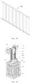
- the present application describes a boom comprising at least one outer profile comprising a lower support rail, and at least one socket cavity, and at least one inner profile comprising a lower projection socket, and at least one socket rectangle, wherein the at least one outer profile and the at least one inner profile are coupled by means of the mechanical union between the at least one socket cavity and the at least one socket rectangle, and between the lower support rail and the lower projection socket.
- the outer profile of the boom allows the installation of light signals and/or a metallic skirt.
- the inner profile of the boom allows the junction of two modules of the outer profile and a length adjustment of said boom.
- the present application describes a barrier mechanism for level crossing control systems. It is an equipment that is designed to maximize the protection in level crossings, mitigating risk behaviour and situations.
- the static and dynamic balance of the main shaft is obtained by means of a set of mechanical elements comprised of steel cams, chains, forks, and a set of compression springs which, when compressed have the function of compensating the moment of force caused by the boom on the main shaft.
- the mechanism is controlled by an automaton which, when it receives the information that the train is approaching, it commands the barrier to lower (obstructing the passage of road vehicles or pedestrians to the railway line), and when it receives the indication of the effective passing of the train, again commands the barrier, this time to rise, enabling once more the road and pedestrian circulation.
- the equalizer system of the main shaft was the solution developed with the purpose of complying with the requirement of absence of conventional counterweights, which are usually used in this type of application.
- the fact that the counterweights are not used results in a reduction of the working space of the arm of the mechanism, and this reduction mitigates the risk of material damage and harm to physical integrity, thus resulting in a system that is conducive to the well-being of all the passers-by on the road and the professionals in the area of railway signalization.
- the function of the equalizer system of the main shaft is to balance the moment of force on the main shaft. This mechanical system compensates the torque generated by the weight of the boom when it is in the horizontal position and balances the forces that are applied to the main shaft when the boom is moving. This compensation of the force applied results in a considerably stable movement of the boom.
- the distinctive factor of the mechanism developed resides in applying a set of compression springs, to guarantee the static balance and the dynamic stability of the boom of the barrier mechanism of a level crossing.
- the solution developed is designed as an integral part of the level crossing system, whereby it is possible to configure lengths, types of signalling and other secondary accessories to better adapt to each scenario and type of installation.
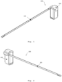
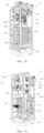
- the present application describes a barrier mechanism (100) for level crossing control systems.
- the barrier mechanism (100) in one of the proposed embodiments, comprises the use of three components, the mechanism (102) itself, the boom (101) and the metallic skirt (103).
- the main function of the barrier mechanism (100) is to protect users in circulation on the road from a situation of imminent danger whenever it is necessary to cross the railway lines.
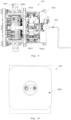
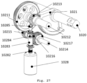
- the mechanism (100) is characterized by the conventional movement, wherein a boom (101) describes a circular movement of 0° (barrier in closed position - horizontal position) to 90° (barrier in open position - vertical position), there existing a boom fixation point (101) to the main shaft (1020) of the mechanism.
- the torque and the speed provided on the main shaft (1020) of the mechanism are resulting from the transmission of the mechanical power of a DC motor (1028), and of a reduction set, comprised by a three-floor reduction, resulting in the mechanical efforts necessary to generate the boom movement.
- this mechanism differs from the overwhelming majority of the equipment in this field of application since the balance system of the main shaft is not made in the conventional manner, resorting to the use of bulky and heavy solid counterweights on the opposite side of the road, which is a solution that is used worldwide.
- This traditional solution due to its robustness and the volume of working space of the counterweights, can cause certain inconveniences to the passers-by and workers that are skilled in the mechanism. These constraints can result in harm to the physical integrity of a passer-by/maintenance technician and in material damages.
- the stability of the movement is internally guaranteed, resulting in the elimination of the volume of working space of the counterweights and in the elimination of the risk deriving from the conventional solution.
- the static and dynamic balance of the main shaft is obtained by means of a set of mechanical elements (steel cam, chains, forks, and spring pack) which have the function of compensating the moment of force caused by the boom on the main shaft.
- the boom (101), used together with the mechanism (102), consists in two profiles that are compatible with each other: the outer profile (1011) and the inner profile (1012).
- the outer profile (1011) is constructively designed to resist the adverse meteorological conditions and has the function of being sufficiently visible to the road users to indicate the presence of a level crossing barrier, allow the installation of light signals as well as the installation of a metallic skirt to obstruct the passage of passers-by through the lower part of the boom.
- the outer profile (1011) of the boom (101) presents, in the lower area, a lower support rail (10111) which is destined to the fixation of accessories, namely, the metallic skirt (103).
- the inner profile (1012) of the boom (101) has two functions: the first one is to unite two modules of the outer boom profile (1011), so that it is possible to configure the boom (101) in several lengths, and the second function is to guarantee that, apart from the fixed length originating from each boom configuration (101), there exists the possibility of customizing and adjusting the final length of the boom (101) at the location of the installation.
- the metallic skirt (103) acts as an accessory and it is conceived to supplement the obstruction of passage exerted by the boom preventing the road users from passing through the lower part of the boom.
- This component is optional and the fixation thereof to the boom can be made by means of screws.
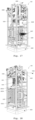
- Main transmission system is the designation given to the set of mechanical elements of the mechanism which has the primary function in the movement of the level crossing barrier. This set is permanently demanded, whether during automatic drive, whether during the manual drive of the mechanism.
- the movement of the mechanism is generated from the electric drive of a motor organ (1028) (CC Motor, 24V, 1500rpm, >1.2 N.m), which has the flange vertically fixed to the metallic structure that gives body to the mechanism.
- This motor organ is responsible for creating the rotation movement (the translation movement is restricted to the three shafts and the rotation axis is perpendicular to the XZ plan) necessary for the automatic operation of the barrier mechanism (101).
- the auxiliary motor shaft is a propelled element which has a rotation speed and rotation direction that is equal to that debited by the motor.
- the worm screw is fixed to the auxiliary shaft of the motor, since it is necessary to transmit the movement to the shaft 1, by means of the semi-globoid crown wheel, wheel 5, which is fixed to the binary limiter that is found keyed to the shaft 1.
- the movement transmission is transversal, irreversible, and has a 40:1 transmission relation. This transmission corresponds to a movement by direct contact by means of a gear joint.
- shaft 1 there is a pinion installed which has the function of a motor on the second transmission floor (4:1 ratio), when transmitting the movement of shaft 1 to shaft 2, by means of a cylindrical gear joint with straight teeth.
- the third transmission floor is the last step in the main transmission, and it guarantees that the upwards movement and the declining movement of the boom are executed, according to the swaying movement of the main shaft.
- a pinion for transmitting the rotation movement to the main shaft which as in the second transmission floor, has a 4:1 transmission relation.
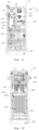
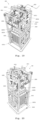
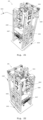
- the equalizer system of the main shaft is the solution developed with the purpose of meeting the requirement of absence of conventional counterweights, which are commonly used in this type of application.
- the fact that the counterweights are not used results in a reduction in the working space of the mechanism. This reduction has the main effect of mitigating the risk of material damage and damage to the physical integrity, thus resulting in a system that is conducive to the well-being of all the road passers-by and the workers in the area of railway signalling.
- the function of the main shaft equalizer system is to balance the moment of force in the main shaft. This mechanical system compensates the torque generated by the weight of the boom when it is in the horizontal position and balances the forces applied to the main shaft when the boom is moving. This instantaneous compensation of the moment of force in the main shaft results in a considerably stable movement of the boom.
- This equalizer system consists in a set of cylindrical compression springs with a configurable distribution, whereby the number thereof can vary between the use of 0 and 14 springs, always in even numbers and distributed in a specific manner, so that the exertion of the springs is always distributed symmetrically and uniformly in the structure that surrounds them.
- the movement responsible for the compression of the set of springs is initiated by the DC motor and is transmitted by the main shaft to the spring pack by means of a flexible intermediary connection, using a set of four transmission chains, which are bolted to the connecting braces, which are components that are directly welded to the main shaft.
- the connecting brace transmits the swaying movement of the main shaft to the chains by means of a dowel which operates as a mechanical joint pin.
- This swaying movement of the connecting brace cam is converted in the translation movement in height of the sliding plate, which is the component that compresses the springs when it is subjected to the exertion of the chains in the upwards direction.
- the movement of the sliding plate is made possible and conducted by two M20 rods, which operate with a translation joint and guarantee the lightness and uniformity of the movement.
- the compression springs in one of the proposed embodiments, present 410mm length, 73mm outer diameter and one compresses 1mm when 18,915 N are applied in the direction of the spring shaft.
- the movement that originates the compression of the spring set is generated in the main shaft and transmitted to the spring set by means of a semi-flexible chain of mechanical elements (connecting brace welded to the shaft, chains, forks, connecting profile and M20 rods), particularly dimensioned and designed for this application.
- the resulting force of this compression maintains the flexible part in constant traction and allows balancing the moment of force in the main shaft.
- the connecting braces are eccentric fixed components having a thickness that is capable of mechanically driving the microswitches.
- the movement that is made by these eccentric components is an alternating curvilinear shuttle movement. It is an upper contact, since the contact is made by means of a line that corresponds to the intersection of the microswitch rolling head and the outer perimeter of the connecting brace.
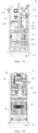
- the handle is installed in the horizontal shaft of the manual drive, and by means of the application of a rotation in the horizontal shaft it is possible to operate the mechanism.
- the movement is originated by the user (maintenance technician of the railway network).
- the engagement point is made by means of a direct transmission using cylindrical gears with straight teeth.
- the rotation movement is transmitted from the reel (10285) to the auxiliary shaft of the motor (10284).
- the components (10282, 10283, 10284 and 10285) have a rotation speed and torque commanded by the user. From the worm screw (10283), the sequence of movements remains the same as that of the automatic drive.
Landscapes
- Engineering & Computer Science (AREA)
- Architecture (AREA)
- Civil Engineering (AREA)
- Structural Engineering (AREA)
- Mechanical Engineering (AREA)
- Forklifts And Lifting Vehicles (AREA)
- Jib Cranes (AREA)
Claims (2)
- Ausleger (101) mit einstellbarer Länge, der mindestens ein Außenprofil (1011) und mindestens ein Innenprofil (1012) umfasst, wobei das Innenprofil (1012) geeignet ist, zwei Außenprofil (1011) mittels einer mechanischen Verbindung zu vereinigen und mechanisch mit dem mindestens ein Außenprofil (1011) gekoppelt ist, dadurch gekennzeichnet, dassdas mindestens eine Außenprofil (1011) eine untere Stützschiene (10111) umfasst, die geeignet ist, Zubehörteile wie eine Metallschürze (103) daran zu befestigen, unddrei Sockelhohlräume (10112),der erste Sockelhohlraum (10112) in der Innenfläche des Außenprofils und in einer gegenüberliegenden Position in Bezug auf die untere Stützschiene (10111) positioniert ist, und der zweite und dritte Sockelhohlraum (10112) in der Innenfläche des Außenprofils (1011) einander gegenüberliegend und in einem 90-Grad-Winkel in Bezug auf den ersten Sockelhohlraum (10112) und die untere Stützschiene (10111) positioniert sind, und das mindestens eine Innenprofil (1012) mit dem mindestens einen Außenprofil (1011) kompatibel ist undeinen unteren Projektionssockel (10121), unddrei Sockelrechtecke (10122), umfasstwobei das erste Sockelrechteck (10122) in der Außenfläche des Innenprofils und in einer gegenüberliegenden Position in Bezug auf den unteren Projektionssockel (10121) positioniert ist, und das zweite und dritte Sockelrechteck (10122) in einer gegenüberliegenden Weise zueinander in der Außenfläche des Innenprofils (1012) und in einem 90-Grad-Winkel in Bezug auf das erste Sockelrechteck (10122) und den unteren Projektionssockel (10121) positioniert sind, wobei das mindestens eine Außenprofil (1011) und das mindestens eine Innenprofil (1012) durch die mechanische Verbindung zwischen den drei Sockelhohlräumen (10112) und den drei Sockelrechtecken (10122) sowie zwischen der unteren Stützschiene (10111) und dem unteren Projektionssockel (10121) gekoppelt sind.
- Ausleger (101) nach dem vorhergehenden Anspruch, wobei die Zubehörteile Lichtsignale und/oder eine Metallschürze (103) umfassen.
Applications Claiming Priority (3)
| Application Number | Priority Date | Filing Date | Title |
|---|---|---|---|
| PT11638020 | 2020-05-14 | ||
| PCT/IB2021/054043 WO2021229459A1 (en) | 2020-05-14 | 2021-05-12 | Barrier mechanism |
| EP21728297.9A EP4150159B1 (de) | 2020-05-14 | 2021-05-12 | Sperrmechanismus |
Related Parent Applications (2)
| Application Number | Title | Priority Date | Filing Date |
|---|---|---|---|
| EP21728297.9A Division EP4150159B1 (de) | 2020-05-14 | 2021-05-12 | Sperrmechanismus |
| EP21728297.9A Division-Into EP4150159B1 (de) | 2020-05-14 | 2021-05-12 | Sperrmechanismus |
Publications (4)
| Publication Number | Publication Date |
|---|---|
| EP4253191A2 EP4253191A2 (de) | 2023-10-04 |
| EP4253191A3 EP4253191A3 (de) | 2023-12-06 |
| EP4253191C0 EP4253191C0 (de) | 2025-03-05 |
| EP4253191B1 true EP4253191B1 (de) | 2025-03-05 |
Family
ID=76159694
Family Applications (2)
| Application Number | Title | Priority Date | Filing Date |
|---|---|---|---|
| EP23182136.4A Active EP4253191B1 (de) | 2020-05-14 | 2021-05-12 | Sperrmechanismus |
| EP21728297.9A Active EP4150159B1 (de) | 2020-05-14 | 2021-05-12 | Sperrmechanismus |
Family Applications After (1)
| Application Number | Title | Priority Date | Filing Date |
|---|---|---|---|
| EP21728297.9A Active EP4150159B1 (de) | 2020-05-14 | 2021-05-12 | Sperrmechanismus |
Country Status (2)
| Country | Link |
|---|---|
| EP (2) | EP4253191B1 (de) |
| WO (1) | WO2021229459A1 (de) |
Family Cites Families (12)
| Publication number | Priority date | Publication date | Assignee | Title |
|---|---|---|---|---|
| US4811516A (en) * | 1986-10-03 | 1989-03-14 | Mobay Corporation | Barrier gate arm |
| US7062879B2 (en) * | 2001-08-08 | 2006-06-20 | Federal Apd, Inc. | Security gate |
| CN2732824Y (zh) * | 2004-09-29 | 2005-10-12 | 深圳市捷顺科技实业有限公司 | 挡车器发光栏杆 |
| KR200448681Y1 (ko) * | 2008-01-28 | 2010-05-07 | (주) 케이 이엔씨 | 난간파이프의 조명등 장착구조 |
| KR100919455B1 (ko) * | 2009-03-26 | 2009-09-28 | 파크너(주) | 차량 안전 차단기용 2색 led 바 |
| JP4938899B2 (ja) * | 2011-04-14 | 2012-05-23 | コーエイ工業株式会社 | 通行遮断竿の駆動装置 |
| US8845125B1 (en) * | 2012-06-01 | 2014-09-30 | GateArm Technologies, Inc. | Vehicle barrier system with illuminating gate arm and method |
| KR101451175B1 (ko) * | 2014-01-06 | 2014-10-15 | 주식회사 라이크텍 | 차량용 차단바 |
| CN204059230U (zh) * | 2014-06-30 | 2014-12-31 | 江西百胜门控设备有限公司 | 一种道闸机芯结构 |
| KR101609770B1 (ko) * | 2015-07-02 | 2016-04-06 | 대경전자시스템(주) | 차량통행 차단기 |
| CN106012898B (zh) * | 2016-05-31 | 2019-06-04 | 中控智慧科技股份有限公司 | 一种道闸机芯 |
| CN209538080U (zh) * | 2018-09-07 | 2019-10-25 | 新乡市中誉鼎力软件科技股份有限公司 | 道闸及车辆用道闸 |
-
2021
- 2021-05-12 EP EP23182136.4A patent/EP4253191B1/de active Active
- 2021-05-12 WO PCT/IB2021/054043 patent/WO2021229459A1/en not_active Ceased
- 2021-05-12 EP EP21728297.9A patent/EP4150159B1/de active Active
Also Published As
| Publication number | Publication date |
|---|---|
| EP4253191C0 (de) | 2025-03-05 |
| EP4150159C0 (de) | 2024-01-24 |
| EP4150159B1 (de) | 2024-01-24 |
| EP4150159A1 (de) | 2023-03-22 |
| WO2021229459A1 (en) | 2021-11-18 |
| EP4253191A3 (de) | 2023-12-06 |
| EP4253191A2 (de) | 2023-10-04 |
Similar Documents
| Publication | Publication Date | Title |
|---|---|---|
| US20130185970A1 (en) | Rotating cantilever post | |
| CN103410107B (zh) | 具有强制停车装置的减速带 | |
| EP4253191B1 (de) | Sperrmechanismus | |
| CN206736770U (zh) | 智能预警限高架 | |
| KR20150117891A (ko) | 도로용 조명장치 | |
| CN103132475B (zh) | 实施为车辆栏障的可弯曲杆的栏障杆 | |
| US20210074187A1 (en) | Rotating cantilever post | |
| KR102545935B1 (ko) | 설비장치의 위치조절이 가능한 지주대 | |
| CN210195430U (zh) | 一种市政工程用升降式围栏 | |
| KR102191526B1 (ko) | 터널용 cctv 회전식 승하강장치 | |
| CN107489942A (zh) | 一种可调高度的路灯 | |
| GB2349653A (en) | Pivotable column | |
| CN207060072U (zh) | 一体式铁路道口装置 | |
| CN113418169B (zh) | 一种具有自动报警功能的市政路灯 | |
| CN214461960U (zh) | 一种带灯栏杆结构 | |
| CN107228310A (zh) | 一种建筑工地用照明灯组件 | |
| CN112837547A (zh) | 一种智慧城市道路通行指示系统 | |
| CN208517833U (zh) | 一种城际轨道交通高架桥的声屏障 | |
| CN214312457U (zh) | 一种地下停车场电子信息指示牌 | |
| CN221942121U (zh) | 一种具有警示功能的施工道路防护栏 | |
| CN111576274A (zh) | 一种道路桥梁用可调式通行限高架 | |
| CN217894969U (zh) | 一种塔吊安全带免拆挂装置 | |
| CN219157454U (zh) | 一种具有发光功能的道路交通标 | |
| CN216712783U (zh) | 桥梁检修工作台 | |
| CN213303474U (zh) | 一种便于安装的交通设施指示牌 |
Legal Events
| Date | Code | Title | Description |
|---|---|---|---|
| PUAI | Public reference made under article 153(3) epc to a published international application that has entered the european phase |
Free format text: ORIGINAL CODE: 0009012 |
|
| STAA | Information on the status of an ep patent application or granted ep patent |
Free format text: STATUS: THE APPLICATION HAS BEEN PUBLISHED |
|
| AC | Divisional application: reference to earlier application |
Ref document number: 4150159 Country of ref document: EP Kind code of ref document: P |
|
| AK | Designated contracting states |
Kind code of ref document: A2 Designated state(s): AL AT BE BG CH CY CZ DE DK EE ES FI FR GB GR HR HU IE IS IT LI LT LU LV MC MK MT NL NO PL PT RO RS SE SI SK SM TR |
|
| PUAL | Search report despatched |
Free format text: ORIGINAL CODE: 0009013 |
|
| AK | Designated contracting states |
Kind code of ref document: A3 Designated state(s): AL AT BE BG CH CY CZ DE DK EE ES FI FR GB GR HR HU IE IS IT LI LT LU LV MC MK MT NL NO PL PT RO RS SE SI SK SM TR |
|
| RIC1 | Information provided on ipc code assigned before grant |
Ipc: B61L 29/02 20060101AFI20231030BHEP |
|
| STAA | Information on the status of an ep patent application or granted ep patent |
Free format text: STATUS: REQUEST FOR EXAMINATION WAS MADE |
|
| 17P | Request for examination filed |
Effective date: 20240403 |
|
| RBV | Designated contracting states (corrected) |
Designated state(s): AL AT BE BG CH CY CZ DE DK EE ES FI FR GB GR HR HU IE IS IT LI LT LU LV MC MK MT NL NO PL PT RO RS SE SI SK SM TR |
|
| GRAP | Despatch of communication of intention to grant a patent |
Free format text: ORIGINAL CODE: EPIDOSNIGR1 |
|
| STAA | Information on the status of an ep patent application or granted ep patent |
Free format text: STATUS: GRANT OF PATENT IS INTENDED |
|
| GRAS | Grant fee paid |
Free format text: ORIGINAL CODE: EPIDOSNIGR3 |
|
| INTG | Intention to grant announced |
Effective date: 20250103 |
|
| GRAA | (expected) grant |
Free format text: ORIGINAL CODE: 0009210 |
|
| STAA | Information on the status of an ep patent application or granted ep patent |
Free format text: STATUS: THE PATENT HAS BEEN GRANTED |
|
| AC | Divisional application: reference to earlier application |
Ref document number: 4150159 Country of ref document: EP Kind code of ref document: P |
|
| AK | Designated contracting states |
Kind code of ref document: B1 Designated state(s): AL AT BE BG CH CY CZ DE DK EE ES FI FR GB GR HR HU IE IS IT LI LT LU LV MC MK MT NL NO PL PT RO RS SE SI SK SM TR |
|
| REG | Reference to a national code |
Ref country code: GB Ref legal event code: FG4D |
|
| REG | Reference to a national code |
Ref country code: CH Ref legal event code: EP |
|
| REG | Reference to a national code |
Ref country code: DE Ref legal event code: R096 Ref document number: 602021027360 Country of ref document: DE |
|
| REG | Reference to a national code |
Ref country code: IE Ref legal event code: FG4D |
|
| U01 | Request for unitary effect filed |
Effective date: 20250403 |
|
| U07 | Unitary effect registered |
Designated state(s): AT BE BG DE DK EE FI FR IT LT LU LV MT NL PT RO SE SI Effective date: 20250410 |
|
| U20 | Renewal fee for the european patent with unitary effect paid |
Year of fee payment: 5 Effective date: 20250527 |
|
| PG25 | Lapsed in a contracting state [announced via postgrant information from national office to epo] |
Ref country code: RS Free format text: LAPSE BECAUSE OF FAILURE TO SUBMIT A TRANSLATION OF THE DESCRIPTION OR TO PAY THE FEE WITHIN THE PRESCRIBED TIME-LIMIT Effective date: 20250605 |
|
| PG25 | Lapsed in a contracting state [announced via postgrant information from national office to epo] |
Ref country code: ES Free format text: LAPSE BECAUSE OF FAILURE TO SUBMIT A TRANSLATION OF THE DESCRIPTION OR TO PAY THE FEE WITHIN THE PRESCRIBED TIME-LIMIT Effective date: 20250305 |
|
| PG25 | Lapsed in a contracting state [announced via postgrant information from national office to epo] |
Ref country code: NO Free format text: LAPSE BECAUSE OF FAILURE TO SUBMIT A TRANSLATION OF THE DESCRIPTION OR TO PAY THE FEE WITHIN THE PRESCRIBED TIME-LIMIT Effective date: 20250605 |
|
| PG25 | Lapsed in a contracting state [announced via postgrant information from national office to epo] |
Ref country code: HR Free format text: LAPSE BECAUSE OF FAILURE TO SUBMIT A TRANSLATION OF THE DESCRIPTION OR TO PAY THE FEE WITHIN THE PRESCRIBED TIME-LIMIT Effective date: 20250305 |
|
| PG25 | Lapsed in a contracting state [announced via postgrant information from national office to epo] |
Ref country code: SM Free format text: LAPSE BECAUSE OF FAILURE TO SUBMIT A TRANSLATION OF THE DESCRIPTION OR TO PAY THE FEE WITHIN THE PRESCRIBED TIME-LIMIT Effective date: 20250305 |
|
| PG25 | Lapsed in a contracting state [announced via postgrant information from national office to epo] |
Ref country code: PL Free format text: LAPSE BECAUSE OF FAILURE TO SUBMIT A TRANSLATION OF THE DESCRIPTION OR TO PAY THE FEE WITHIN THE PRESCRIBED TIME-LIMIT Effective date: 20250305 |
|
| PG25 | Lapsed in a contracting state [announced via postgrant information from national office to epo] |
Ref country code: CZ Free format text: LAPSE BECAUSE OF FAILURE TO SUBMIT A TRANSLATION OF THE DESCRIPTION OR TO PAY THE FEE WITHIN THE PRESCRIBED TIME-LIMIT Effective date: 20250305 |
|
| PG25 | Lapsed in a contracting state [announced via postgrant information from national office to epo] |
Ref country code: SK Free format text: LAPSE BECAUSE OF FAILURE TO SUBMIT A TRANSLATION OF THE DESCRIPTION OR TO PAY THE FEE WITHIN THE PRESCRIBED TIME-LIMIT Effective date: 20250305 |
|
| PG25 | Lapsed in a contracting state [announced via postgrant information from national office to epo] |
Ref country code: IS Free format text: LAPSE BECAUSE OF FAILURE TO SUBMIT A TRANSLATION OF THE DESCRIPTION OR TO PAY THE FEE WITHIN THE PRESCRIBED TIME-LIMIT Effective date: 20250705 |