EP4253178A1 - System zur auswahl eines fahrmodus eines fahrzeugs und verfahren dafür - Google Patents
System zur auswahl eines fahrmodus eines fahrzeugs und verfahren dafür Download PDFInfo
- Publication number
- EP4253178A1 EP4253178A1 EP23160636.9A EP23160636A EP4253178A1 EP 4253178 A1 EP4253178 A1 EP 4253178A1 EP 23160636 A EP23160636 A EP 23160636A EP 4253178 A1 EP4253178 A1 EP 4253178A1
- Authority
- EP
- European Patent Office
- Prior art keywords
- mode
- vehicle
- switch
- control unit
- throttle
- Prior art date
- Legal status (The legal status is an assumption and is not a legal conclusion. Google has not performed a legal analysis and makes no representation as to the accuracy of the status listed.)
- Pending
Links
- 238000000034 method Methods 0.000 title claims description 33
- 230000007704 transition Effects 0.000 description 5
- 230000001133 acceleration Effects 0.000 description 4
- 239000000725 suspension Substances 0.000 description 4
- 230000008859 change Effects 0.000 description 3
- 238000002485 combustion reaction Methods 0.000 description 2
- 230000036461 convulsion Effects 0.000 description 2
- 238000010586 diagram Methods 0.000 description 2
- 230000007246 mechanism Effects 0.000 description 1
- 230000004048 modification Effects 0.000 description 1
- 238000012986 modification Methods 0.000 description 1
- 238000005457 optimization Methods 0.000 description 1
- 238000003825 pressing Methods 0.000 description 1
- 230000008569 process Effects 0.000 description 1
Images


Classifications
-
- B—PERFORMING OPERATIONS; TRANSPORTING
- B60—VEHICLES IN GENERAL
- B60W—CONJOINT CONTROL OF VEHICLE SUB-UNITS OF DIFFERENT TYPE OR DIFFERENT FUNCTION; CONTROL SYSTEMS SPECIALLY ADAPTED FOR HYBRID VEHICLES; ROAD VEHICLE DRIVE CONTROL SYSTEMS FOR PURPOSES NOT RELATED TO THE CONTROL OF A PARTICULAR SUB-UNIT
- B60W10/00—Conjoint control of vehicle sub-units of different type or different function
- B60W10/04—Conjoint control of vehicle sub-units of different type or different function including control of propulsion units
- B60W10/06—Conjoint control of vehicle sub-units of different type or different function including control of propulsion units including control of combustion engines
-
- B—PERFORMING OPERATIONS; TRANSPORTING
- B60—VEHICLES IN GENERAL
- B60W—CONJOINT CONTROL OF VEHICLE SUB-UNITS OF DIFFERENT TYPE OR DIFFERENT FUNCTION; CONTROL SYSTEMS SPECIALLY ADAPTED FOR HYBRID VEHICLES; ROAD VEHICLE DRIVE CONTROL SYSTEMS FOR PURPOSES NOT RELATED TO THE CONTROL OF A PARTICULAR SUB-UNIT
- B60W10/00—Conjoint control of vehicle sub-units of different type or different function
- B60W10/04—Conjoint control of vehicle sub-units of different type or different function including control of propulsion units
- B60W10/08—Conjoint control of vehicle sub-units of different type or different function including control of propulsion units including control of electric propulsion units, e.g. motors or generators
-
- B—PERFORMING OPERATIONS; TRANSPORTING
- B60—VEHICLES IN GENERAL
- B60W—CONJOINT CONTROL OF VEHICLE SUB-UNITS OF DIFFERENT TYPE OR DIFFERENT FUNCTION; CONTROL SYSTEMS SPECIALLY ADAPTED FOR HYBRID VEHICLES; ROAD VEHICLE DRIVE CONTROL SYSTEMS FOR PURPOSES NOT RELATED TO THE CONTROL OF A PARTICULAR SUB-UNIT
- B60W20/00—Control systems specially adapted for hybrid vehicles
- B60W20/10—Controlling the power contribution of each of the prime movers to meet required power demand
-
- B—PERFORMING OPERATIONS; TRANSPORTING
- B60—VEHICLES IN GENERAL
- B60W—CONJOINT CONTROL OF VEHICLE SUB-UNITS OF DIFFERENT TYPE OR DIFFERENT FUNCTION; CONTROL SYSTEMS SPECIALLY ADAPTED FOR HYBRID VEHICLES; ROAD VEHICLE DRIVE CONTROL SYSTEMS FOR PURPOSES NOT RELATED TO THE CONTROL OF A PARTICULAR SUB-UNIT
- B60W30/00—Purposes of road vehicle drive control systems not related to the control of a particular sub-unit, e.g. of systems using conjoint control of vehicle sub-units
- B60W30/18—Propelling the vehicle
- B60W30/182—Selecting between different operative modes, e.g. comfort and performance modes
-
- B—PERFORMING OPERATIONS; TRANSPORTING
- B60—VEHICLES IN GENERAL
- B60W—CONJOINT CONTROL OF VEHICLE SUB-UNITS OF DIFFERENT TYPE OR DIFFERENT FUNCTION; CONTROL SYSTEMS SPECIALLY ADAPTED FOR HYBRID VEHICLES; ROAD VEHICLE DRIVE CONTROL SYSTEMS FOR PURPOSES NOT RELATED TO THE CONTROL OF A PARTICULAR SUB-UNIT
- B60W50/00—Details of control systems for road vehicle drive control not related to the control of a particular sub-unit, e.g. process diagnostic or vehicle driver interfaces
- B60W50/08—Interaction between the driver and the control system
- B60W50/082—Selecting or switching between different modes of propelling
-
- B—PERFORMING OPERATIONS; TRANSPORTING
- B60—VEHICLES IN GENERAL
- B60W—CONJOINT CONTROL OF VEHICLE SUB-UNITS OF DIFFERENT TYPE OR DIFFERENT FUNCTION; CONTROL SYSTEMS SPECIALLY ADAPTED FOR HYBRID VEHICLES; ROAD VEHICLE DRIVE CONTROL SYSTEMS FOR PURPOSES NOT RELATED TO THE CONTROL OF A PARTICULAR SUB-UNIT
- B60W2300/00—Indexing codes relating to the type of vehicle
- B60W2300/36—Cycles; Motorcycles; Scooters
-
- B—PERFORMING OPERATIONS; TRANSPORTING
- B60—VEHICLES IN GENERAL
- B60W—CONJOINT CONTROL OF VEHICLE SUB-UNITS OF DIFFERENT TYPE OR DIFFERENT FUNCTION; CONTROL SYSTEMS SPECIALLY ADAPTED FOR HYBRID VEHICLES; ROAD VEHICLE DRIVE CONTROL SYSTEMS FOR PURPOSES NOT RELATED TO THE CONTROL OF A PARTICULAR SUB-UNIT
- B60W2520/00—Input parameters relating to overall vehicle dynamics
- B60W2520/10—Longitudinal speed
-
- B—PERFORMING OPERATIONS; TRANSPORTING
- B60—VEHICLES IN GENERAL
- B60W—CONJOINT CONTROL OF VEHICLE SUB-UNITS OF DIFFERENT TYPE OR DIFFERENT FUNCTION; CONTROL SYSTEMS SPECIALLY ADAPTED FOR HYBRID VEHICLES; ROAD VEHICLE DRIVE CONTROL SYSTEMS FOR PURPOSES NOT RELATED TO THE CONTROL OF A PARTICULAR SUB-UNIT
- B60W2540/00—Input parameters relating to occupants
- B60W2540/06—Ignition switch
-
- B—PERFORMING OPERATIONS; TRANSPORTING
- B60—VEHICLES IN GENERAL
- B60W—CONJOINT CONTROL OF VEHICLE SUB-UNITS OF DIFFERENT TYPE OR DIFFERENT FUNCTION; CONTROL SYSTEMS SPECIALLY ADAPTED FOR HYBRID VEHICLES; ROAD VEHICLE DRIVE CONTROL SYSTEMS FOR PURPOSES NOT RELATED TO THE CONTROL OF A PARTICULAR SUB-UNIT
- B60W2540/00—Input parameters relating to occupants
- B60W2540/10—Accelerator pedal position
-
- B—PERFORMING OPERATIONS; TRANSPORTING
- B60—VEHICLES IN GENERAL
- B60W—CONJOINT CONTROL OF VEHICLE SUB-UNITS OF DIFFERENT TYPE OR DIFFERENT FUNCTION; CONTROL SYSTEMS SPECIALLY ADAPTED FOR HYBRID VEHICLES; ROAD VEHICLE DRIVE CONTROL SYSTEMS FOR PURPOSES NOT RELATED TO THE CONTROL OF A PARTICULAR SUB-UNIT
- B60W2540/00—Input parameters relating to occupants
- B60W2540/12—Brake pedal position
-
- B—PERFORMING OPERATIONS; TRANSPORTING
- B60—VEHICLES IN GENERAL
- B60W—CONJOINT CONTROL OF VEHICLE SUB-UNITS OF DIFFERENT TYPE OR DIFFERENT FUNCTION; CONTROL SYSTEMS SPECIALLY ADAPTED FOR HYBRID VEHICLES; ROAD VEHICLE DRIVE CONTROL SYSTEMS FOR PURPOSES NOT RELATED TO THE CONTROL OF A PARTICULAR SUB-UNIT
- B60W2540/00—Input parameters relating to occupants
- B60W2540/215—Selection or confirmation of options
Definitions
- the present invention generally relates to a system for selecting a ride mode in a vehicle and a method thereof.
- a rider In a conventional electric or hybrid vehicle, a rider is provided with a feature where rider can select among multiple ride modes available in the vehicle. Different ride modes are provided for range optimization of the vehicle, based on the route taken by the rider. These modes can be either economy mode or power mode or any other mode depending upon the requirement of the rider. In economy mode, less battery energy is consumed while in power mode, more battery energy is consumed.
- Ride mode can be selected either from the beginning when the vehicle starts or one can switch to other modes while riding the vehicle.
- a switch is provided to switch amongst the available drive modes.
- the rider has to be aware of how many times he has to press the switch or how long he has to press the switch to select the different modes. Also, such switches when pressed accidentally may also change the mode since there is no interlock for change in the mode of the vehicle.
- a default ride mode is set and if the rider wants to switch to the other ride mode, then in that case the vehicle has to be driven for some duration and then only it can switch to the other ride mode.
- the jerky ride or sudden acceleration and deceleration in transition between the ride modes will also lead to poor performance of the battery and the motor.
- the present invention is directed towards a system for selecting a ride mode of a vehicle.
- the system has a first switch disposed on the vehicle in proximity to a rider.
- the first switch generates a first input signal to switch to one of a first mode and a second mode from an idle mode.
- the system further has a second switch disposed on the vehicle in proximity to the rider.
- the second switch generates a second input signal to switch between the first mode and the second mode.
- a control unit is communicably coupled to the first switch and the second switch.
- the control unit is configured to select the ride mode to be one of an idle mode, the first mode and the second mode of the vehicle. The selection is based on a combination of one or more vehicle parameters, the first signal, and the second signal in real-time.
- the control unit is configured to start the vehicle in the idle mode when a key is operated or by keyless authentication.
- the control unit receives the one or more vehicle parameters from a plurality of sensors of the vehicle or a Vehicle Control Unit (VCU).
- the control unit further receives the first input signal and a brake signal from a brake switch for a pre-defined time.
- the control unit is configured to switch to one of the first mode or the second mode from the idle mode when the first input signal and the brake signal are received and the one or more vehicle parameters satisfy a pre-defined set of conditions.
- the control unit is further configured to receive the second input signal and a throttle input value from a throttle position sensor (TPS).
- TPS throttle position sensor
- the control unit is configured to switch from the first mode to the second mode when the second input signal is received and the throttle input value is less than a first throttle threshold. Or the control unit is configured to switch from the second mode to the first mode when the second input signal is received, the throttle input value is less than a second throttle threshold and a vehicle speed is less than a threshold speed.
- control unit is configured to prohibit the switching from the second mode to the first mode on receiving the second input signal when the throttle input value is greater than a second throttle threshold and/or the vehicle speed is greater than the threshold speed.
- the one or more vehicle parameters received by the control unit has a battery charger connection status, a side stand switch status, the vehicle turned OFF status and an idling time of the vehicle.
- one of the first mode and the second mode is a default mode set by the rider or an Original Equipment Manufacturer (OEM).
- OEM Original Equipment Manufacturer
- the first mode is an economy mode and the second mode is a power mode.
- the first switch and the second switch are a press and release switch.
- the method for selecting a ride mode of a vehicle has the steps of receiving starting a vehicle by a control unit in an idle mode as the ride mode of the vehicle when a key is operated or by keyless authentication; receiving by the control unit one or more vehicle parameters from at least one of a plurality of sensors and Vehicle Control Unit (VCU); generating by a first switch a first input signal to switch to a default mode from an idle mode, the default mode being one of a first mode and a second mode; receiving by the control unit the first input signal and a brake signal from a brake switch for a pre-defined time; switching the ride mode of the vehicle from the idle mode to one of the first mode and the second mode by the control unit when the first input signal and the brake signal are received, and the one or more vehicle parameters satisfy a pre-defined set of conditions; and, generating by a second switch a second input signal to switch between the first mode and the second mode.
- VCU Vehicle Control Unit
- the method further has the steps of receiving by the control unit the second input signal and a throttle input value from a throttle position sensor (TPS) and switching by the control unit the ride mode between the first mode and the second mode on receiving the second signal, throttle input value, when the vehicle is in motion.
- TPS throttle position sensor
- the method has the steps of switching the ride mode of vehicle from the first mode to the second mode by the control unit when the second input signal is received and the throttle input value is less than a first throttle threshold; or switching from the second mode to the first mode by the control unit when the second input signal is received the throttle input value is less than a second throttle threshold and a vehicle speed is less than a threshold speed.
- the method has the step of prohibiting by the control unit the switching from the second mode to the first mode on receiving the second input signal when the throttle input value is greater than a second throttle threshold and/or the vehicle speed is greater than the threshold speed.
- the one or more parameters includes a battery charger connection status, a side stand switch status, the vehicle turned OFF status and an idling time of the vehicle.
- the first mode is an economy mode and the second mode is a power mode.
- the first switch and the second switch are a press and release switch.
- the default mode is set by the rider or an Original Equipment Manufacturer (OEM).
- OEM Original Equipment Manufacturer
- the vehicle is a two-wheeled electric vehicle.
- the disclosure in the present invention may be applied to any automobile capable of accommodating the present subject matter without defeating the scope of the present invention.
- the vehicle 100 is a scooter type two-wheeled vehicle in the illustrated embodiments.
- the vehicle 100 is an electric or a hybrid vehicle. It may be contemplated that the vehicle 100 can be any other kind of two-wheeled vehicle or three-wheeled vehicle.
- the illustrated examples of two-wheeled scooter vehicle should not be meant limiting the scope of the present invention.
- the terms “electric vehicle” and “vehicle” are interchangeably used in this disclosure. However, both the terms “electric vehicle” and “vehicle” are one and the same, and the term “vehicle” is used for brevity.
- FIG. 1 illustrates a schematic view of a vehicle 100, in accordance with an embodiment of the present invention.
- the motor vehicle 100 is a scooter type vehicle.
- the vehicle 100 has a prime mover (not shown) that is disposed behind a floorboard 104 and below a seat assembly 122 and/or a storage bin (not shown).
- the prime mover is one of an internal combustion engine or an electric motor adapted to provide motive force for vehicle movement.
- the vehicle 100 has a front wheel 126, a rear wheel 128 and a frame member (not shown).
- a floorboard assembly (not shown) is mounted for supporting feet of a rider.
- a head pipe connects to the frame member (not shown).
- the head pipe supports a steering shaft (not shown) and a front suspension (not shown) attached to the steering shaft through a lower bracket [not shown].
- the front suspension supports the front wheel 126.
- the upper portion of the front wheel 126 is covered by a front fender 130 mounted to the front suspension.
- the front fender 130 is movable along with the front wheel 126, during travel over undulations on a road surface.
- a handlebar 132 is fixed to upper bracket (not shown) and can rotate about the steering shaft for turning the vehicle 200.
- a headlight (not shown), a visor guard 134 and instrument cluster (not shown) is arranged on an upper portion of the head pipe.
- a rear suspension (not shown) is provided to the rear wheel 128 for dampening the vibrations induced during travel of the vehicle 100 over undulations on the road surface.
- a taillight unit 136 is disposed at the end of the vehicle 100 and at the rear of the seat assembly 122.
- a grab rail 138 is also provided for facilitating the grip and/or balance to the rider on the vehicle 200 during movement.
- the vehicle 100 further includes a front wheel 126 and a rear wheel 128 driven by an electric motor (not shown) or an Internal Combustion engine. The electric motor receives a traction power from one or more power sources like a battery (not shown) for movement of the vehicle 100.
- a rear fender 140 is disposed above the rear wheel 128.
- Figure 2 illustrates a block diagram of the system 200 for selecting a ride mode of the vehicle 100.
- the system 200 is on-board the vehicle 100.
- the system 200 comprises a first switch 260, a second switch 270, and a control unit 250.
- the first switch 260 is disposed on the vehicle 100 in proximity to a rider.
- the first switch 260 is configured to generate a first input signal to switch to one of a first mode and a second mode from an idle mode.
- one of the first mode and the second mode is a default mode set by the rider or an Original Equipment Manufacturer (OEM).
- OEM Original Equipment Manufacturer
- the rider can select any ride mode as the default mode for the vehicle 100 via his mobile app.
- the first mode is an economy mode and the second mode is a power mode.
- the economy mode consumes less battery energy while the power mode consumes more battery energy.
- the vehicle 100 On starting the vehicle 100, the vehicle 100 is in idle mode and stationary.
- the vehicle 100 On pressing the first switch 260, the vehicle 100 switches from idle mode to the economy or power mode, whichever is set as default mode.
- the system 200 further comprises the second switch 270 disposed on the vehicle 100 in proximity to the rider.
- the second switch 270 is configured to generate a second input signal to switch between the first mode and the second mode.
- the first switch 260 and the second switch 270 are press and release switches.
- a brake switch 220 is provided in the existing brake lever of the vehicle 100.
- the brake switch 220 will provide a signal to a control unit 250 upon operation of the brake lever.
- the first switch 260, the second switch 270 and the brake switch 220 are communicably coupled to the control unit 250.
- the control unit 250 will receive a first input signal, a second input signal and a brake signal upon operating the first switch 260, the second switch 260 and the brake switch 220 respectively.
- the control unit 250 controls a traction motor 280 to meet the desired output speed based on the throttle input value received from a throttle position sensor (TPS) 210 and battery State of charge.
- TPS throttle position sensor
- the control unit 250 is connected with motor 280 to receive the hall sensor signal and compute the motor RPM and vehicle speed accordingly.
- the control unit 250 is configured to start the vehicle 100 in the idle mode when a key is operated or by keyless authentication.
- the control unit 250 is further configured to receive one or more vehicle parameters from a plurality of sensors of the vehicle 100 or a Vehicle Control Unit (VCU) 230.
- the plurality of sensors includes but is not limited to the brake switch 220, a vehicle speed sensor and the throttle position sensor (TPS) 210.
- the control unit 250 receives one or more vehicle parameters from VCU 230 and a battery charger 222 through a communication bus such as CAN.
- the communication bus has been represented by dotted lines in Figure 2 .
- the one or more vehicle parameters received by the control unit 250 comprise the battery charger connection status, a side stand switch status, the vehicle turned OFF status, and an idling time of the vehicle.
- the control unit 250 is further configured to select the ride mode to be one of the idle mode, the first mode and the second mode of the vehicle 100 which is based on a combination of one or more vehicle parameters, the first signal, and the second signal in real-time.
- the control unit 250 when the first switch 260 is pressed and the brake lever (not shown) is operated for a predefined time, the control unit 250 will receive the first input signal and the brake signal.
- the control unit 250 is further configured to switch to one of the first mode or the second mode from the idle mode when the first input signal and the brake signal are received, and the one or more vehicle parameters satisfy a pre-defined set of conditions.
- the pre-defined set of conditions comprise the condition when the side stand is not engaged, brake engaged, battery charger not operational, an idling time of the vehicle is greater than 5 seconds, and the battery charge level is sufficient to start. When conditions like these are satisfied then only the vehicle 100 will switch to one of the first mode or the second mode from the idle mode.
- the control unit 250 is configured to receive the second input signal when the second switch 270 is pressed and the throttle input value from the throttle position sensor (TPS) 210.
- TPS throttle position sensor
- control unit 250 is configured to prohibit the switching from the second mode to the first mode on receiving the second input signal when the throttle input value is greater than the second throttle threshold and/or the vehicle speed is greater than the threshold speed.
- the vehicle 100 is configured such that a top speed of 45km/hr is set for the first mode and a top speed of 80km/hr is set for the second mode.
- the first threshold throttle value is 15%
- the second threshold throttle value is 40%
- the threshold speed to change ride mode from the second mode to the first mode is 40 km/h.
- the vehicle 100 will switch to the second mode from the first mode only when the throttle input value is less than the first throttle threshold such as 15%.
- the throttle input value is 100% and the vehicle 100 is running at 80 km/h, then the rider will feel the loss of throttle control over the vehicle 100 and vehicle starts decelerating to the top speed of the first mode. This sudden deceleration is prevented by the present invention.
- the vehicle 100 will not switch to the first mode from the second mode even when the second switch 270 is pressed because the throttle input value is greater than the second throttle threshold and/or the vehicle speed is greater than the threshold speed.
- the vehicle 100 enters the idle mode when it is started then the ride mode is to be selected.
- the selection of ride mode is made in such a way that the vehicle 100 enters a default riding mode on starting vehicle or resetting or turning OFF of the vehicle and enter into a previous driven mode if the vehicle 100 is not power reset.
- the present invention relates to a method 300 for selecting a ride mode of a vehicle, as referenced above.
- Figure 3A illustrates the method steps involved in the method 300.
- the vehicle 100 is started by a control unit 250 in an idle mode as the ride mode of the vehicle 100 when a key is operated or by keyless authentication.
- one or more vehicle parameters are received by the control unit 250.
- the one or more vehicle parameters are received from at least one of a plurality of sensors and Vehicle Control Unit (VCU) 230.
- the one or more parameters comprising a battery charger connection status, a side stand switch status, the vehicle turned OFF status and an idling time of the vehicle 100.
- a first input signal is generated by a first switch 260.
- the first input signal switches to a default mode from an idle mode when the default mode being one of a first mode and a second mode.
- the first switch 260 is a press and release switch.
- one of the first mode and the second mode is a default mode set by the rider or an Original Equipment Manufacturer (OEM).
- OEM Original Equipment Manufacturer
- the rider can select any ride mode as the default mode for the vehicle 100 via his/her mobile application.
- the first mode is an economy mode and the second mode is a power mode. The economy mode consumes less battery energy while the power mode consumes more battery energy. In the idle mode, the vehicle 100 is ready to get started but it is not in the motion state.
- the first input signal and a brake signal from a brake switch 220 are received by the control unit 250 for a pre-defined time.
- the ride mode of the vehicle 100 is switched from the idle mode to one of the first mode and the second mode by the control unit 250 when the first input signal and the brake signal are received and the one or more vehicle parameters satisfy a pre-defined set of conditions.
- the pre-defined set of conditions comprise the condition when the side stand is not engaged, brake engaged, battery charger not operational, an idling time of the vehicle is greater than 5 seconds, and the battery charge level is sufficient to start.
- a second input signal is generated by the control unit 250 to switch between the first mode and the second mode.
- the second switch 270 is a press and release switch.
- the second input signal and a throttle input value from a throttle position sensor (TPS) 210 are generated by the control unit 250.
- TPS throttle position sensor
- the ride mode is switched between the first mode and the second mode by the control unit 250 on receiving the second signal, throttle input value, when the vehicle 100 is in motion.
- FIG. 4A , 4B , 4C and 4D illustrates, the method steps involved in the method 300 for selecting a ride mode of the vehicle 100.
- the vehicle 100 is started by a control unit 250 in an idle mode as the ride mode of the vehicle 100 when a key is operated or by keyless authentication.
- one or more vehicle parameters are received by the control unit 250.
- the one or more vehicle parameters are received from at least one of a plurality of sensors and Vehicle Control Unit (VCU) 230.
- the one or more parameters include a battery charger connection status, a side stand switch status, the vehicle turned OFF status and an idling time of the vehicle 100.
- the first input signal and a brake signal from a brake switch 220 are received by the control unit 250 for a pre-defined time.
- the ride mode of the vehicle 100 is switched to a default mode from the idle mode by the control unit 250 when the first input signal and the brake signal are received and the one or more vehicle parameters satisfy a pre-defined set of conditions.
- the default mode being one of the first mode and the second mode. If the control unit 250 does not receive the first input signal and the brake signal and the one or more vehicle parameters are not satisfying the pre-defined set of conditions, then the vehicle 100 will remain in idle mode and will not switch to any ride mode and the method 300 reverts to step 402.
- the pre-defined set of conditions comprise the condition when the side stand is not engaged, brake engaged, battery charger not operational, an idling time of the vehicle is greater than 5 seconds, and the battery charge level is sufficient to start.
- step 410 the vehicle 100 is switched to a first mode as the default mode when the first switch 260 and the brake switch 220 are pressed and the one or more vehicle parameters satisfy a pre-defined set of conditions. Thereafter the method 300 proceeds to step 414 (as illustrated in Figure 4B ).
- step 420 the method 300 proceeds to step 420 from step 412 (as illustrated in Figure 4C ).
- the control unit 250 receives a throttle input value from a throttle position sensor (TPS) and runs the motor 280 and the vehicle 100 accordingly.
- TPS throttle position sensor
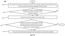
- the control unit 250 will receive the second input signal when the second switch 270 is pressed. If the second input signal is received by the control unit 250 and the throttle input value is less than a first throttle threshold, then at step 418, the control unit 250 will switch the vehicle 100 from the first mode to the second mode. If the second switch 270 is not pressed and the throttle input value is not less than the first throttle threshold, then the vehicle 100 will remain in the first mode and the method 300 reverts to step 414.
- the method 300 comprises the steps of prohibiting by the control unit 250, the switching from the second mode to the first mode on receiving the second input signal when the throttle input value is greater than the second throttle threshold and/or the vehicle speed is greater than the threshold speed.
- the method 300 from step 414 moves to step 426.
- the control unit 250 receives the throttle input value from the throttle position sensor (TPS) 210 and runs the motor 280 and the vehicle 100 accordingly.
- TPS throttle position sensor
- the vehicle 100 will switch from the first mode to the second mode.
- step 428 if the second switch 270 is not pressed and the throttle input value is not less than the second throttle threshold, then the method 300 reverts to step 426.
- the second switch 270 is pressed again to switch from the second mode to the first mode and if the throttle input value is greater than the second throttle threshold or/and the vehicle speed is greater than the threshold speed, then at step 434, the control unit 250 will receive the input but will not respond to mode switch operation. The vehicle 100 will remain in second mode.
- the method 300 proceeds to step 420.
- the control unit 250 receives a throttle input value from a throttle position sensor (TPS) 210 and runs the motor 280 and the vehicle 100 accordingly in the second mode.
- TPS throttle position sensor
- the control unit 250 will receive the second input signal when the second switch 270 is pressed. If the second input signal is received by the control unit 250 and the throttle input value is less than a second throttle threshold and a vehicle speed is less than the threshold speed, at step 424, then the control unit 250 will switch the vehicle 100 from the second mode to the first mode and runs the vehicle 100 according to the received throttle input value. If the second switch 270 is not pressed and the throttle input value is not less than the second throttle threshold and the vehicle speed is not less than the threshold speed, then vehicle 100 will remain in the second mode and the method 300 reverts to step 420.
- the present invention provides smooth switching from low energy mode (economy mode) to high energy mode (power mode) and the rider does not feel any jerk or discomfort.
- the present invention provides a mechanism for interlock to avoid such transition.
- the present invention tried to solve the problem of the jerky ride or sudden acceleration and deceleration in transition between the ride modes. It will also increase the performance of the battery and the motor 280. Also, the present invention suggests the system where not only an unintended selection of drive mode is avoided but also at the same time facilitates a smooth transition between the modes of the vehicle 100. It also eases the process of selection of a ride mode and also changing the ride modes comfortably even while riding the vehicle 100. So, the present invention suggests a system that eliminates the confusion regarding operation of the switch while riding. As per the present invention, the rider can avoid accidental conditions in the vehicle 100, such side stand getting actuated or the vehicle 100 getting turned off, in such cases the mode switching is disabled.
Landscapes
- Engineering & Computer Science (AREA)
- Chemical & Material Sciences (AREA)
- Combustion & Propulsion (AREA)
- Transportation (AREA)
- Mechanical Engineering (AREA)
- Automation & Control Theory (AREA)
- Human Computer Interaction (AREA)
- Electric Propulsion And Braking For Vehicles (AREA)
Applications Claiming Priority (1)
| Application Number | Priority Date | Filing Date | Title |
|---|---|---|---|
| IN202241019769 | 2022-03-31 |
Publications (1)
| Publication Number | Publication Date |
|---|---|
| EP4253178A1 true EP4253178A1 (de) | 2023-10-04 |
Family
ID=85511152
Family Applications (1)
| Application Number | Title | Priority Date | Filing Date |
|---|---|---|---|
| EP23160636.9A Pending EP4253178A1 (de) | 2022-03-31 | 2023-03-08 | System zur auswahl eines fahrmodus eines fahrzeugs und verfahren dafür |
Country Status (1)
| Country | Link |
|---|---|
| EP (1) | EP4253178A1 (de) |
Citations (3)
| Publication number | Priority date | Publication date | Assignee | Title |
|---|---|---|---|---|
| US20070276549A1 (en) * | 2006-05-23 | 2007-11-29 | Kenji Hijikata | Driving force control apparatus of vehicle |
| US20130030604A1 (en) * | 2011-07-29 | 2013-01-31 | Takeru Ohshima | Control system for vehicle, vehicle having the control system, and controlling method thereof |
| US20210170909A1 (en) * | 2019-12-10 | 2021-06-10 | Hyundai Motor Company | Apparatus for controlling fuel cell of environment-friendly vehicle, system including the same, and method thereof |
-
2023
- 2023-03-08 EP EP23160636.9A patent/EP4253178A1/de active Pending
Patent Citations (3)
| Publication number | Priority date | Publication date | Assignee | Title |
|---|---|---|---|---|
| US20070276549A1 (en) * | 2006-05-23 | 2007-11-29 | Kenji Hijikata | Driving force control apparatus of vehicle |
| US20130030604A1 (en) * | 2011-07-29 | 2013-01-31 | Takeru Ohshima | Control system for vehicle, vehicle having the control system, and controlling method thereof |
| US20210170909A1 (en) * | 2019-12-10 | 2021-06-10 | Hyundai Motor Company | Apparatus for controlling fuel cell of environment-friendly vehicle, system including the same, and method thereof |
Similar Documents
| Publication | Publication Date | Title |
|---|---|---|
| US8812174B2 (en) | Control system for vehicle, vehicle having the control system, and controlling method thereof | |
| JP4655723B2 (ja) | 車両およびその制御方法 | |
| US5533583A (en) | Non-trackbound vehicle with an electrodynamic converter and a throttle | |
| JP4225314B2 (ja) | ハイブリッド車両 | |
| US6358180B1 (en) | Engine control system and method | |
| US9145130B2 (en) | Vehicle travel control device | |
| US10336329B2 (en) | Saddled vehicle | |
| US8855873B2 (en) | Shift controlling apparatus | |
| CN111491837B (zh) | 休闲车 | |
| JP4682174B2 (ja) | 車両のエネルギ回生装置 | |
| EP4253178A1 (de) | System zur auswahl eines fahrmodus eines fahrzeugs und verfahren dafür | |
| JP2014230456A (ja) | 車両用制動制御装置 | |
| JP2014201124A (ja) | 車両用制動制御装置 | |
| CN113428226B (zh) | 行驶中调头场景识别控制方法及系统 | |
| KR101977414B1 (ko) | 스마트 전기자동차 및 이의 운용방법 | |
| JP7364072B2 (ja) | 車両制御装置 | |
| JP5794047B2 (ja) | 自動二輪車の制御装置 | |
| JP4196397B2 (ja) | 車両用駆動装置 | |
| JP6053099B2 (ja) | ハイブリッド車両の駆動制御装置 | |
| JPH0516872A (ja) | 前後輪駆動二輪車 | |
| KR101977415B1 (ko) | 스마트 전기자동차 및 이의 운용방법 | |
| JPH10318012A (ja) | 車両用制御装置 | |
| JP7545319B2 (ja) | ハイブリッド車両の制御装置、ハイブリッド車両及び制御方法 | |
| CN113715945B (zh) | 用于鞍乘型车辆的开关单元 | |
| KR101548914B1 (ko) | 전기자동차 |
Legal Events
| Date | Code | Title | Description |
|---|---|---|---|
| PUAI | Public reference made under article 153(3) epc to a published international application that has entered the european phase |
Free format text: ORIGINAL CODE: 0009012 |
|
| STAA | Information on the status of an ep patent application or granted ep patent |
Free format text: STATUS: THE APPLICATION HAS BEEN PUBLISHED |
|
| AK | Designated contracting states |
Kind code of ref document: A1 Designated state(s): AL AT BE BG CH CY CZ DE DK EE ES FI FR GB GR HR HU IE IS IT LI LT LU LV MC ME MK MT NL NO PL PT RO RS SE SI SK SM TR |
|
| STAA | Information on the status of an ep patent application or granted ep patent |
Free format text: STATUS: REQUEST FOR EXAMINATION WAS MADE |
|
| 17P | Request for examination filed |
Effective date: 20231030 |
|
| RBV | Designated contracting states (corrected) |
Designated state(s): AL AT BE BG CH CY CZ DE DK EE ES FI FR GB GR HR HU IE IS IT LI LT LU LV MC ME MK MT NL NO PL PT RO RS SE SI SK SM TR |
|
| GRAP | Despatch of communication of intention to grant a patent |
Free format text: ORIGINAL CODE: EPIDOSNIGR1 |
|
| STAA | Information on the status of an ep patent application or granted ep patent |
Free format text: STATUS: GRANT OF PATENT IS INTENDED |
|
| RIC1 | Information provided on ipc code assigned before grant |
Ipc: B60W 50/08 20200101ALI20240531BHEP Ipc: B60W 30/182 20200101ALI20240531BHEP Ipc: B60W 20/10 20160101ALI20240531BHEP Ipc: B60W 10/08 20060101ALI20240531BHEP Ipc: B60W 10/06 20060101AFI20240531BHEP |
|
| INTG | Intention to grant announced |
Effective date: 20240617 |