EP4251944B1 - Geschoss und verfahren zum stoppen von luftfahrzeugen - Google Patents
Geschoss und verfahren zum stoppen von luftfahrzeugen Download PDFInfo
- Publication number
- EP4251944B1 EP4251944B1 EP21897258.6A EP21897258A EP4251944B1 EP 4251944 B1 EP4251944 B1 EP 4251944B1 EP 21897258 A EP21897258 A EP 21897258A EP 4251944 B1 EP4251944 B1 EP 4251944B1
- Authority
- EP
- European Patent Office
- Prior art keywords
- filament
- projectile
- bunch
- packing plate
- filaments
- Prior art date
- Legal status (The legal status is an assumption and is not a legal conclusion. Google has not performed a legal analysis and makes no representation as to the accuracy of the status listed.)
- Active
Links
Images

Classifications
-
- F—MECHANICAL ENGINEERING; LIGHTING; HEATING; WEAPONS; BLASTING
- F41—WEAPONS
- F41H—ARMOUR; ARMOURED TURRETS; ARMOURED OR ARMED VEHICLES; MEANS OF ATTACK OR DEFENCE, e.g. CAMOUFLAGE, IN GENERAL
- F41H11/00—Defence installations; Defence devices
- F41H11/02—Anti-aircraft or anti-guided missile or anti-torpedo defence installations or systems
- F41H11/04—Aerial barrages
-
- B—PERFORMING OPERATIONS; TRANSPORTING
- B64—AIRCRAFT; AVIATION; COSMONAUTICS
- B64U—UNMANNED AERIAL VEHICLES [UAV]; EQUIPMENT THEREFOR
- B64U70/00—Launching, take-off or landing arrangements
- B64U70/30—Launching, take-off or landing arrangements for capturing UAVs in flight by ground or sea-based arresting gear, e.g. by a cable or a net
-
- F—MECHANICAL ENGINEERING; LIGHTING; HEATING; WEAPONS; BLASTING
- F41—WEAPONS
- F41H—ARMOUR; ARMOURED TURRETS; ARMOURED OR ARMED VEHICLES; MEANS OF ATTACK OR DEFENCE, e.g. CAMOUFLAGE, IN GENERAL
- F41H13/00—Means of attack or defence not otherwise provided for
-
- F—MECHANICAL ENGINEERING; LIGHTING; HEATING; WEAPONS; BLASTING
- F42—AMMUNITION; BLASTING
- F42B—EXPLOSIVE CHARGES, e.g. FOR BLASTING, FIREWORKS, AMMUNITION
- F42B12/00—Projectiles, missiles or mines characterised by the warhead, the intended effect, or the material
- F42B12/02—Projectiles, missiles or mines characterised by the warhead, the intended effect, or the material characterised by the warhead or the intended effect
- F42B12/36—Projectiles, missiles or mines characterised by the warhead, the intended effect, or the material characterised by the warhead or the intended effect for dispensing materials; for producing chemical or physical reaction; for signalling ; for transmitting information
-
- F—MECHANICAL ENGINEERING; LIGHTING; HEATING; WEAPONS; BLASTING
- F42—AMMUNITION; BLASTING
- F42B—EXPLOSIVE CHARGES, e.g. FOR BLASTING, FIREWORKS, AMMUNITION
- F42B12/00—Projectiles, missiles or mines characterised by the warhead, the intended effect, or the material
- F42B12/02—Projectiles, missiles or mines characterised by the warhead, the intended effect, or the material characterised by the warhead or the intended effect
- F42B12/36—Projectiles, missiles or mines characterised by the warhead, the intended effect, or the material characterised by the warhead or the intended effect for dispensing materials; for producing chemical or physical reaction; for signalling ; for transmitting information
- F42B12/56—Projectiles, missiles or mines characterised by the warhead, the intended effect, or the material characterised by the warhead or the intended effect for dispensing materials; for producing chemical or physical reaction; for signalling ; for transmitting information for dispensing discrete solid bodies
-
- F—MECHANICAL ENGINEERING; LIGHTING; HEATING; WEAPONS; BLASTING
- F42—AMMUNITION; BLASTING
- F42B—EXPLOSIVE CHARGES, e.g. FOR BLASTING, FIREWORKS, AMMUNITION
- F42B12/00—Projectiles, missiles or mines characterised by the warhead, the intended effect, or the material
- F42B12/02—Projectiles, missiles or mines characterised by the warhead, the intended effect, or the material characterised by the warhead or the intended effect
- F42B12/36—Projectiles, missiles or mines characterised by the warhead, the intended effect, or the material characterised by the warhead or the intended effect for dispensing materials; for producing chemical or physical reaction; for signalling ; for transmitting information
- F42B12/56—Projectiles, missiles or mines characterised by the warhead, the intended effect, or the material characterised by the warhead or the intended effect for dispensing materials; for producing chemical or physical reaction; for signalling ; for transmitting information for dispensing discrete solid bodies
- F42B12/70—Projectiles, missiles or mines characterised by the warhead, the intended effect, or the material characterised by the warhead or the intended effect for dispensing materials; for producing chemical or physical reaction; for signalling ; for transmitting information for dispensing discrete solid bodies for dispensing radar chaff or infrared material
Definitions
- the solution relates to deterring unmanned aerial vehicles (UAV).
- UAV unmanned aerial vehicles
- UAVs are easy to come by and their controllability, range, and load-carrying capacity are continuously increasing, so using them to cause damage is also increasing.
- the disclosed solution comprises a projectile which comprises a shell and a bunch of filaments, the bunch being wound in a coil, and the bunch being placed within the shell.
- the projectile according to the invention may be delivered to the target with different methods and by using various means.
- the projectile may be fired by making use of compressed air or a propulsion charge, by using a compressed air weapon or grenade launcher, for example.
- the projectile may also be taken to the target by using a rocket or an aerial vehicle.
- the length of the filaments is 8 to 16 metres.
- the filaments comprised by the bunch are fastened together at substantially one end thereof. Fastening together at one end may have the advantage of the handling of the bunches of filaments becoming easier.
- the projectile comprises a packing plate.
- the packing plate comprises a substantially circular plate-like piece substantially corresponding to the size of the diameter of a coil formed by a filament bunch substantially wound in a coil, that is, a filament coil.
- the size of the packing plate may vary.
- the size of the packing plate may vary according to the length, thickness, or material of the filaments, for example. In an example the diameter of the packing plate is 40 to 120 mm.
- An advantage of using a packing plate may also be that the handling of coiled filament bunches is facilitated when the filament coils do not get stuck to each other. In addition, the coils are easier to store.
- the filament bunch is fastened at one end to the packing plate.
- the filament bunch is fastened at one end to the centre part of the packing plate.
- the filament coil formed by filaments wound in a coil and the packing plate are mutually parallel.
- Being parallel means that the planar surface of the packing plate and the upper or lower surface of the filament coil are in the same direction.
- the filament coil may rest on the packing plate.
- the projectile as its outermost part, comprises a shell within which one or more filament coils may be placed.
- at least three filament coils are placed inside the projectile shell.
- the projectile comprises means to open the shell.
- An advantage of the means for opening the shell is an increase in the reliability of the projectile.
- the projectile and propulsion charge are both arranged inside a case.
- the projectile comprises the propulsion charge and, as the outermost part, the case.
- An advantage of using a propulsion charge may be increasing the range of the projectile.
- a further advantage may be an increase in the speed of the projectile.
- the advantages of increasing the speed and range are that the obstacle can be fanned out in the air in the shortest possible time. The obstacle may also be fanned out on the basis of the detected trajectory of the aerial vehicles instead of prediction.
- the disclosed solution comprises a projectile which comprises a shell and a bunch of filaments.
- the filament bunch is wound in a coil and the bunch placed inside the shell.
- the projectile according to the invention may be delivered to the target with different methods and by using various means.
- the projectile may be fired by making use of compressed air or a propulsion charge, by using a compressed air weapon or grenade launcher, for example.
- the projectile may also be taken to the target by using a rocket or an aerial vehicle. Taking to a target comprises carrying or moving the projectile to an intended area in the air.
- the intended area may be determined in advance to secure a specific area in connection with a public event, or the intended area may be determined reactively on the basis of observations.
- At least one filament bunch wound in a coil and included in the shell is released in the air from the shell, and the filament bunch opens up and descends towards the ground supported by the packing plate.
- the filament bunch floating in the air produces an obstacle in the air for the operation of an aerial vehicle.
- Hitting an aerial vehicle air current from a propeller of an aerial vehicle, or a propeller of an aerial vehicle causes the filament bunch to loosen.
- the filaments included in the bunch may, for example, be sucked in the motor of the aerial vehicle, get entangled in its rotors and stop them, or get stuck on the aerial vehicle surface thereby harming its flight characteristics.
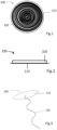
- Figure 1 shows a top view of a filament coil 100.
- the filament coil 100 comprises a filament bunch 105 rolled up in a coil. Additionally in the example of Figure 1 , the filament coil comprises a packing plate 110.
- the filament bunch 105 comprises at least 100 filaments.
- a filament bunch according to an example may comprise 500 to 50000 filaments, advantageously 10000 to 30000 filaments, and particularly advantageously 10000 to 15000 filaments.
- a filament bunch according to an example comprises at least 1000 filaments.
- a filament bunch according to an example comprise no more than 50000 filaments.
- An increase in the number of filaments comprised by a filament bunch increases the thickness of the filament bunch. With an increase in the thickness, the length of the filament bunch has to be decreased if the diameter of the filament coil is not to be increased. If the goal is to use a grenade launcher or compressed air weapon, for example, to shoot the projectiles, the diameter of the projectile has to be adapted to suit them. It is also possible to make projectiles of a larger diameter for shooting with other means, whereby the carbon fibre tow used in them may comprise more than 50000 filaments and/or the length of the carbon fibre tow may be longer than that disclosed herein.
- the filament bunch may be, for example, 0.1 to 10 mm thick, or, for example, 0.1 to 5 mm.
- the cross section of a filament bunch may be round or alternatively deviating from a round cross section, such as flat.
- the thickness of a flat filament bunch may be, for example, 0.1 to 5 mm and the width in this case 0.3 to 10 mm, for example.
- the length of the filament affects the size of the obstacle that the filament bunch creates in the air, and the descend rate of the filament bunch because length increases weight.
- the weight of the filament bunch is affected by its thickness and length.
- the filament length may vary between 1 and 30 metres.
- the length of the filaments may advantageously be between 8 and 16 metres, preferably between 10 and 14 metres, whereby the filament bunch creates big enough a floating obstacle without too fast a descend caused by the length-induced weight.
- the filaments may have been made of different materials.
- the filaments may have been made of carbon fibre, for example.
- the term carbon fibre tow may be used of the filament bunch. In a filament bunch, the filaments are not intertwined or twisted together but they are bunched laterally in parallel.
- An advantage of manufacturing of carbon fibre is the lightness of carbon fibre, which allows a large number of filaments to be packed in one projectile.
- a further advantage of carbon fibre is the good tensile strength due to which the filament does not snap when it finds its way to the rotors or motor of an aerial vehicle, but it may get entangled in the motor or rotors causing them to stop or break.
- a further advantage of carbon fibre is its electrical conductivity which may cause a short circuit or another electrical failure when sucked into the motor of an aerial vehicle.
- the filaments comprised by the filament bunch are substantially fastened together at one end.
- Substantially fastening together at one end comprises fastening together at the remotest end of the filaments, or in relation to the filament length, at a short distance from it.
- the filaments may be fastened together at one end, only, whereby the filaments comprised by the other end of the filament bunch are left free.
- Connecting the filaments together at one end may also comprise connecting without a separate fastening means used for fastening the filament bunch.
- the filament bunch may be fastened directly to the packing plate.
- the filament coil shown in Figure 1 comprises a packing plate.
- the packing plate may be made of different materials such as plastic, paper, cardboard, or paperboard.
- the physical shape of the packing plate may be substantially round, whereby its shape corresponds with the shape of a coiled filament bunch.
- the size of the packing plate may correspond substantially with the size of the filament bunch so that the diameter of the filament bunch is substantially the same as the diameter of the packing plate.
- the filament bunch may be fixed at one end to the packing plate and wound in a coil parallel with the packing plate, or the filament bunch wound in a coil may be fastened at one end to the packing plate.
- the centre points of the packing plate and filament disc are substantially at the same point.
- the filament bunch wound in a coil is opened in the air.
- the air drag of the packing plate is larger than that of the filament bunch, which means that when descending the packing plate acts as a decelerator for the sinking of the filament bunch.
- the air drag of the packing plate which is larger than that of the filament bunch, also causes the filament bunch fixed at one end to the packing plate to hang substantially downwards from the packing plate.
- the filament bunch fixed to the packing plate is fixed to the packing plate so that the end of the filament bunch where the filaments included in the filament bunch are fastened together is fixed to the packing plate.
- the end of the filament bunch which comprises filaments not fastened together, will be the furthest from the packing plate.
- the filament bunch hanging from the packing plate is spread in the airspace within the scope of its length.
- a filament bunch fastened at one end to the packing plate may be wound in a coil so that one end of the filament bunch is fastened to the centre of the packing plate and the remaining filament bunch is wound around it. Furthermore, with the filaments comprised by a filament bunch being fastened together at one end, the filament bunch is attached to the packing plate at the end where the filaments comprised by the filament bunch are fastened together, whereby the free ends of the filaments comprised by the filament bunch will be the furthest from the packing plate.
- the filament coil begins to open up.
- the air drag of the packing plate slows the packing plate down, whereby the filament bunch wound in a coil begins to unwind by the effect of gravity.
- the opened the filament bunch is hanging from the centre point of the packing plate.
- the filaments comprised by a filament bunch are fastened together at substantially the centre of the filament bunch, and the filament bunch is fixed by its centre point to the packing plate.
- the opened filament disc is floating down from the sky, supported from the packing plate, filament bunch ends of substantially the same length are hanging down from both sides of the fastening point.
- the packing plate comprises edges that surround the outer edge of the packing plate substantially at a 90-degree angle in relation to the packing plate.
- the round part of the packing plate forms the bottom and the edges form a wall whose height substantially corresponds with the lateral height of the filament coil to be placed inside them.
- an advantage may be a further facilitation in handling the filament coils.
- the packing plate comprises holes or other openings through which air can flow as the projectile is floating downward.
- An advantage of the openings comprised by the packing plate may be control of the airflow, whereby as an opened filament disc is floating downward, with the packing plate acting as a decelerator, a better balance may be achieved and thereby the operating period increased as long as possible.
- Figure 2 shows a side view of a filament coil 100.
- the filament bunch 105 and packing plate 110 are substantially parallel to each other.
- the packing plate and filament bunch wound in a coil are substantially of the same size. Being parallel may be an advantage in handling the filament coils 100 because the packing plate 110 and filament bunch 105 stay together better.
- a further advantage is that the diameter of the projectile is kept adequately small whereby no separate means are needed to fire it, but commonly used means such as grenade launchers or compressed air weapons may be used.
- Figure 3 shows an opened filament coil 100 descending from the sky, in which a filament bunch 105 unwound from a coil is hanging from the packing plate 110.
- the filaments included in the filament bunch are fastened together at one end.
- the filaments comprised by the filament bunch are fastened together at one end, only.
- the filament bunch is fixed to the packing plate at the end where the filaments are fastened ttogether, so the end of the filament bunch where the filaments are free will be hanging the furthest from the packing plate.
- the filament bunch and packing plate are floating downwards with the packing plate acting as a decelerator.
- a filament separated from the bunch may cause the aerial vehicle to fall by sticking to its rotors or being sucked in its motor through, for example, an air intake.
- a filament made of carbon fibre may also stick on the surface of the aerial vehicle, either making it fall or harming its flight characteristics and controllability.
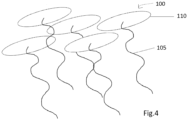
- Figure 4 shows an example of a curtain-like obstacle formed by a plurality of opened filament coils 100 floating from the sky.
- a curtain-like obstacle may be created by firing a projectile comprising a plurality of filament coils into the sky. Once the filament coils included in the projectile have been released into the sky, the filament bunch comprised by them open up and the opened filament coils float, hanging from the packing plate, towards the ground.
- FIG. 5 shows a side view of a cross section for a projectile 101 where filament coils 100, either stacked one on the other or successively, have been placed inside the shell 120.
- the shell 120 comprises an opening 121 through which the filament coils placed inside the shell may be released once the projectile has been fired in the air.
- the filament coils are placed inside the shell and set radially as well as one on the other.
- a radial placement comprises setting the filament coils in a fan-like manner, partly parallel and partly one on the other, whereby one layer comprises, instead of one, a plurality of filament coils. There may be a plurality of such layers one on the other.
- Such an arrangement is advantageous, if the goal is to include a large number of filament coils in a projectile.
- the shell comprised by the projectile may comprise a case, sheath, or another reinforcement inside which necessary means, such as filament coils, may be placed.
- necessary means such as filament coils
- the material of the shell comprised by the projectile may be metal, such as steel or aluminium, or it may be plastic or cardboard, for example.
- the shell is made of polyethylene PE or polypropylene PP.
- the shell may also be made of a material that is destroyed by burning, for example, when a spreading charge has exploded once the projectile has reached a suitable height.
- the front of the shell comprises a first end in the firing direction
- the rear end of the shell comprises a second end in the firing direction.
- the shell may be open at both the front and rear ends.
- the shell may also be open at one end and closed at another end.
- the shell may also closed at both ends.
- the shell may additionally comprise means to open the shell.
- the example of Figure 6 shows a side view of a cross section for a projectile 101 where filament coils 100 and a spreading charge 125 have been placed inside the shell 120.
- the spreading charge may open the shell or push the filament coils out of the shell.
- the spreading charge may comprise gunpowder or another pyrotechnic substance producing plenty of gas pressure or volume.
- An advantage of using spreading charges may be an increase in the reliability of the projectile and the timeliness of the release of the filament discs.
- the use of spreading charges may be applicable when projectiles are fired far away or when using a strong or durable material in the projectile shell.
- the means for opening the shell may also comprise modifications made in the shell, furthering the shell to open.
- modifications made in the projectile shell which further the shell to open and the release of the filament coils included therein.
- the shell is open at one end, whereby the filament coils may be released through the opening into the sky.
- the example of Figure 7 shows a side view of a cross section for a projectile 101 where filament coils 100 and a spreading charge 125 have been adapted inside the shell 120.
- the example of Figure 7 comprises a propulsion charge 130 and, as the outermost part, a case 135.
- the propulsion charge 130 and shell 120 which comprises the filament coils 100 and spreading charge 125 have been placed inside the case 135.
- the propulsion charge may comprise, for example, gunpowder or another pyrotechnic substance producing plenty of gas pressure or volume.
- An advantage of using a propulsion charge may be that the projectile may be fired further away, or a faster flight speed achieved than without a propulsion charge.
- the propulsion charge may comprise, for example, gunpowder or another pyrotechnic substance producing plenty of gas pressure or volume.
- the propulsion charge may elevate or direct the projectile to a desired distance which may be further away than the distance achieved without the help of the propulsion charge.
- the case 135 may be made of, for example, a metal such as steel or another suitable material. Using a case provides the advantage that the use of a propulsion charge is possible.
- An advantage of the projectile according to the disclosed solution may be that it is possible to form in the air obstacles as needed to protect certain areas. Obstacles may be formed in the air to be on the safe side, anticipating a situation, or the projectile may be fired reactively onto the flight path of a detected aerial vehicle.
- the projectile according to the solution is environmentally safe and may be used in city centres, for example, where precautionary measures based on firing with live ammunition are not available.
- a further advantage of the projectile is its scalability both in relation to the size and firing methods. Furthermore, an advantage of the projectile is its simplicity due to which the projectile may be difficult to detect or interfere with.
Landscapes
- Engineering & Computer Science (AREA)
- General Engineering & Computer Science (AREA)
- Aviation & Aerospace Engineering (AREA)
- Chemical & Material Sciences (AREA)
- Combustion & Propulsion (AREA)
- Remote Sensing (AREA)
- Radar, Positioning & Navigation (AREA)
- Aiming, Guidance, Guns With A Light Source, Armor, Camouflage, And Targets (AREA)
- Forklifts And Lifting Vehicles (AREA)
- Jib Cranes (AREA)
- Emergency Lowering Means (AREA)
Claims (14)
- Projektil, wobei das Projektil (101) Folgendes umfassteine Hülle (120) undein Bündel (105) von Filamenten,wobei das Bündel (105) zu einer Spule aufgewickelt ist unddas Bündel (105) in der Hülle (120) angeordnet ist,dadurch gekennzeichnet,dass die Filamente aus Kohlenstofffasern bestehen, wobei das Filamentbündel (105) ein Kohlenstofffaserkabel ist, das mindestens 1000 Filamente umfasst.
- Projektil nach Anspruch 1, wobei die Filamente, aus denen das Bündel (105) besteht, im Wesentlichen an einem Ende miteinander verbunden sind.
- Projektil nach Anspruch 1 oder 2, wobei das Filamentbündel (105) höchstens 50.000 Filamente umfasst.
- Projektil nach einem der vorhergehenden Ansprüche, wobei das Filamentbündel (105) 10.000 bis 30.000 Filamente umfasst.
- Projektil nach einem der vorhergehenden Ansprüche, wobei die Länge des Filamentbündels (105) 8 bis 16 Meter beträgt.
- Projektil nach einem der vorhergehenden Ansprüche, wobei der Außendurchmesser des Projektils (101) 40 bis 120 mm beträgt.
- Projektil nach einem der vorhergehenden Ansprüche, umfassend eine Füllplatte (110).
- Projektil nach Anspruch 7, wobei die Füllplatte (110) aus Kunststoff, Karton, Papier oder Pappe besteht.
- Projektil nach einem der Ansprüche 7 bis 8, wobei die durch das zu einer Spule gewickelte Filamentbündel (105) gebildete Filamentspule (100) und die Füllplatte (110) zueinander parallel sind.
- Projektil nach einem der Ansprüche 7 bis 9, wobei das Filamentbündel (105) an einem Ende am Mittelteil der Verpackungsplatte (110) befestigt ist.
- Projektil nach einem der vorhergehenden Ansprüche, wobei mindestens drei Filamentspulen (100) in der Hülle (120) angeordnet sind.
- Projektil nach einem der vorhergehenden Ansprüche, umfassend Mittel zum Öffnen der Hülle (120).
- Projektil nach einem der vorhergehenden Ansprüche, umfassend eine Treibladung (130) und eine Hülle (135) als äußersten Teil.
- Verfahren zum Stoppen von Luftfahrzeugen, wobei das Verfahren das Bilden eines Hindernisses in der Luft durch Verwendung eines Projektils (101) nach einem der Ansprüche 1 bis 13 umfasst.
Priority Applications (1)
| Application Number | Priority Date | Filing Date | Title |
|---|---|---|---|
| EP25170678.4A EP4559821A3 (de) | 2020-11-24 | 2021-11-22 | Geschoss und verfahren zum stoppen von luftfahrzeugen |
Applications Claiming Priority (2)
| Application Number | Priority Date | Filing Date | Title |
|---|---|---|---|
| FI20206193A FI130227B (fi) | 2020-11-24 | 2020-11-24 | Ammus ja menetelmä lennokkien pysäyttämiseksi |
| PCT/FI2021/050800 WO2022112653A1 (en) | 2020-11-24 | 2021-11-22 | Projectile and method for stopping aerial vehicles |
Related Child Applications (1)
| Application Number | Title | Priority Date | Filing Date |
|---|---|---|---|
| EP25170678.4A Division EP4559821A3 (de) | 2020-11-24 | 2021-11-22 | Geschoss und verfahren zum stoppen von luftfahrzeugen |
Publications (4)
| Publication Number | Publication Date |
|---|---|
| EP4251944A1 EP4251944A1 (de) | 2023-10-04 |
| EP4251944A4 EP4251944A4 (de) | 2024-10-30 |
| EP4251944B1 true EP4251944B1 (de) | 2025-04-30 |
| EP4251944C0 EP4251944C0 (de) | 2025-04-30 |
Family
ID=81755371
Family Applications (2)
| Application Number | Title | Priority Date | Filing Date |
|---|---|---|---|
| EP25170678.4A Pending EP4559821A3 (de) | 2020-11-24 | 2021-11-22 | Geschoss und verfahren zum stoppen von luftfahrzeugen |
| EP21897258.6A Active EP4251944B1 (de) | 2020-11-24 | 2021-11-22 | Geschoss und verfahren zum stoppen von luftfahrzeugen |
Family Applications Before (1)
| Application Number | Title | Priority Date | Filing Date |
|---|---|---|---|
| EP25170678.4A Pending EP4559821A3 (de) | 2020-11-24 | 2021-11-22 | Geschoss und verfahren zum stoppen von luftfahrzeugen |
Country Status (10)
| Country | Link |
|---|---|
| US (1) | US12352536B2 (de) |
| EP (2) | EP4559821A3 (de) |
| JP (1) | JP2023551296A (de) |
| KR (1) | KR20230154417A (de) |
| AU (1) | AU2021386487A1 (de) |
| CA (1) | CA3199375A1 (de) |
| ES (1) | ES3027981T3 (de) |
| FI (1) | FI130227B (de) |
| IL (1) | IL303155A (de) |
| WO (1) | WO2022112653A1 (de) |
Families Citing this family (1)
| Publication number | Priority date | Publication date | Assignee | Title |
|---|---|---|---|---|
| US20250290733A1 (en) * | 2024-02-05 | 2025-09-18 | Nl Enterprises, Llc | Projectile Construction and Payloads Therefor |
Family Cites Families (84)
| Publication number | Priority date | Publication date | Assignee | Title |
|---|---|---|---|---|
| GB274695A (en) * | 1926-11-17 | 1927-07-28 | Alfred Craig | Improvements in or relating to toy bombs or projectors |
| US2274655A (en) * | 1937-03-18 | 1942-03-03 | Bickel Erich | Aerial multimine |
| US2296980A (en) * | 1940-10-17 | 1942-09-29 | Oric Scott Hober | Shell |
| US3575083A (en) * | 1968-12-09 | 1971-04-13 | Stanford Research Inst | Antenna wire launcher and bobbin projectile |
| US3760735A (en) * | 1971-12-03 | 1973-09-25 | P Schmitt | Visual aid for sportsman gunning |
| US4055247A (en) * | 1976-10-22 | 1977-10-25 | The United States Of America As Represented By The United States Energy Research And Development Administration | Explosion containment device |
| US4271761A (en) * | 1979-04-23 | 1981-06-09 | The United States Of America As Represented By The Administrator Of The National Aeronautics And Space Administration | High acceleration cable deployment system |
| US4327644A (en) * | 1979-05-01 | 1982-05-04 | Stahan Corporation | Projectile deployed cable weapons system |
| US4651999A (en) * | 1986-07-18 | 1987-03-24 | Sturm Michael O | Arrow string tracking apparatus |
| US4750692A (en) * | 1987-04-07 | 1988-06-14 | Howard Thomas R | Satellite retrieval apparatus |
| US5493627A (en) * | 1988-01-15 | 1996-02-20 | Sippican, Inc. | Waveguide pack |
| US5033385A (en) * | 1989-11-20 | 1991-07-23 | Hercules Incorporated | Method and hardware for controlled aerodynamic dispersion of organic filamentary materials |
| US5177316A (en) * | 1991-01-18 | 1993-01-05 | Honigsbaum Richard F | Process and apparatus for attacking rotating wing aircraft |
| DE69310379T3 (de) * | 1992-10-13 | 2000-09-07 | Alliedsignal Inc., Morristown | Verflochtenes garn mit hoher festigkeit und daraus hergestellter stoff |
| US5315932A (en) * | 1993-05-25 | 1994-05-31 | Bertram Charles H | Ensnaring shot cartridge |
| US5460155A (en) * | 1993-12-07 | 1995-10-24 | Hobbs, Ii; James C. | Behavior deterrence and crowd management |
| US5448937A (en) * | 1994-08-12 | 1995-09-12 | Buc; Steven M. | Muzzle launched grapnel hook projectile |
| US5698815A (en) * | 1995-12-15 | 1997-12-16 | Ragner; Gary Dean | Stun bullets |
| US5637825A (en) * | 1996-01-17 | 1997-06-10 | The United States Of America As Represented By The Secretary Of The Navy | Control line spool |
| US5996504A (en) * | 1997-07-07 | 1999-12-07 | Lowery; Samuel R. | Barbed wire deployment apparatus |
| FR2808323A1 (fr) * | 2000-04-27 | 2001-11-02 | Lacroix Soc E | Systeme de lancement de charge ou projectile a freinage filaire controle |
| US6392213B1 (en) * | 2000-10-12 | 2002-05-21 | The Charles Stark Draper Laboratory, Inc. | Flyer assembly |
| US20050075043A1 (en) * | 2003-02-05 | 2005-04-07 | Lorenzana Moises B. | Air propelled party streamer device |
| BRPI0418300B8 (pt) * | 2004-01-01 | 2021-07-27 | Dsm Ip Assets Bv | fio de multifilamentos de polietileno de alto desempenho e processo para fabricação do mesmo |
| US7950329B1 (en) * | 2006-11-17 | 2011-05-31 | Oleg Nemtyshkin | Cartridge for remote electroshock weapon |
| US7786417B2 (en) * | 2006-12-11 | 2010-08-31 | Dese Research, Inc. | RAM neutralization system and method |
| GR1006044B (el) * | 2007-02-22 | 2008-09-03 | Soukos Robots Abee | Ελαφρου βαρους ηλεκτρονικος θωρακας προστασιας απο ρουκετοφορες βομβιδες με προωθητηρα |
| US7882775B2 (en) * | 2007-08-07 | 2011-02-08 | Engineering Science Analysis Corporation | Non-lethal restraint device with diverse deployability applications |
| US8601928B2 (en) * | 2007-08-07 | 2013-12-10 | Engineering Science Analysis Corp. | Restraint device for use in an aquatic environment |
| GB2454704B (en) * | 2007-11-16 | 2012-05-02 | Richard Allen | A method of manufacturing a fibrous structure and an apparatus therefor |
| US8024889B2 (en) * | 2008-06-25 | 2011-09-27 | Brett Bunker | Pest control method and apparatus |
| US8434711B2 (en) * | 2008-12-31 | 2013-05-07 | Joel F. Berman | Unguided missile and projectile defense shield supported by tethered balloons |
| US8375837B2 (en) * | 2009-01-19 | 2013-02-19 | Honeywell International Inc. | Catch and snare system for an unmanned aerial vehicle |
| US8082849B2 (en) | 2009-03-31 | 2011-12-27 | The United States Of America As Represented By The Secretary Of The Navy | Short term power grid disruption device |
| US8100359B2 (en) * | 2009-03-31 | 2012-01-24 | Qasem Awadh Al-Qaffas | Intercept system for falling bombs |
| US7987791B2 (en) | 2009-03-31 | 2011-08-02 | United States Of America As Represented By The Secretary Of The Navy | Method of disrupting electrical power transmission |
| US20100242775A1 (en) * | 2009-03-31 | 2010-09-30 | John Felix Schneider | Short Term Power Grid Disruption Device |
| US8783185B2 (en) * | 2009-06-11 | 2014-07-22 | Raytheon Company | Liquid missile projectile for being launched from a launching device |
| US8402894B1 (en) * | 2010-06-09 | 2013-03-26 | The United States Of America As Represented By The Secretary Of The Navy | Boat propeller entanglement apparatus and munition |
| DK2479327T3 (en) * | 2011-01-20 | 2019-03-04 | Tape Weaving Sweden Ab | Textile materials comprising strips in two oblique orientations and composite materials comprising such materials |
| US8596178B2 (en) * | 2011-01-28 | 2013-12-03 | The Boeing Company | Expanding countermeasure and launcher system |
| US8918970B2 (en) * | 2011-12-21 | 2014-12-30 | GKN Aerospace Services Structures, Corp. | Hoop tow modification for a fabric preform for a composite component |
| CN104487340B (zh) * | 2012-05-30 | 2017-08-01 | 线路发射器控股有限公司 | 缆线传送设备 |
| US9074858B2 (en) * | 2012-07-13 | 2015-07-07 | The Boeing Company | Projectile-deployed countermeasure system |
| US9074856B1 (en) * | 2013-04-18 | 2015-07-07 | The United States Of America As Represented By The Secretary Of The Army | Gun-launched anchor projectile for climbing |
| US9260204B2 (en) * | 2013-08-09 | 2016-02-16 | The Aerospace Corporation | Kinetic energy storage and transfer (KEST) space launch system |
| TWI688951B (zh) | 2014-10-30 | 2020-03-21 | 日商索尼半導體解決方案公司 | 非揮發性記憶體裝置 |
| GB2538826B (en) * | 2015-04-22 | 2021-06-23 | Openworks Eng Ltd | System for deploying a first object for capturing, immobilising or disabling a second object |
| US10006747B2 (en) | 2015-07-25 | 2018-06-26 | Nathan Cohen | Drone mitigation methods and apparatus |
| US10663266B2 (en) * | 2015-08-27 | 2020-05-26 | Airspace Systems, Inc. | Interdiction system and method of operation |
| US20170219317A1 (en) * | 2016-01-29 | 2017-08-03 | Stan William Sands | Counter drone device, and method of using the same |
| CN105711850A (zh) * | 2016-01-30 | 2016-06-29 | 上海仪耐新材料科技有限公司 | 一种网弹式反无人机智能拦截系统 |
| WO2017160750A1 (en) * | 2016-03-12 | 2017-09-21 | Kestrel Science and Innovation, LLC | Interdiction and recovery for small unmanned aircraft systems |
| US10107599B2 (en) * | 2016-03-25 | 2018-10-23 | Wrap Technologies, Inc. | Entangling projectiles and systems for their use |
| US10036615B2 (en) * | 2016-03-25 | 2018-07-31 | Wrap Technologies, Inc. | Entangling projectile deployment system |
| US9975632B2 (en) * | 2016-04-08 | 2018-05-22 | Drona, LLC | Aerial vehicle system |
| JP6413057B2 (ja) * | 2016-07-20 | 2018-10-31 | 株式会社プロドローン | 無人航空機および移動体捕捉システム |
| EP3548832B1 (de) * | 2016-12-02 | 2021-10-27 | Skysec GmbH | Flugkörper zum abfangen von fremddrohnen |
| US10926875B2 (en) * | 2016-12-14 | 2021-02-23 | Sanmina Corporation | Devices and methods for facilitating capture of unmanned aerial vehicles |
| US10435153B2 (en) | 2016-12-14 | 2019-10-08 | Sanmina Corporation | Nets and devices for facilitating capture of unmanned aerial vehicles |
| US11757561B2 (en) * | 2017-01-10 | 2023-09-12 | AIRSHARE, Inc. | System and method for intercepting unmanned aerial vehicles |
| US10619988B2 (en) * | 2017-02-03 | 2020-04-14 | Sanmina Corporation | Devices and methods for facilitating blast and dispersion mitigation |
| US9989336B2 (en) * | 2017-02-17 | 2018-06-05 | James W. Purvis | Device for non-lethal immobilization of threats |
| US20180257780A1 (en) | 2017-03-09 | 2018-09-13 | Jeffrey Sassinsky | Kinetic unmanned aerial vehicle flight disruption and disabling device, system and associated methods |
| WO2019074573A1 (en) | 2017-10-11 | 2019-04-18 | Raytheon Company | DIRECTED POWER DELIVERY SYSTEMS THAT CAN REMOVE ENEMY AIRWAY THREATS |
| SG11202007355TA (en) * | 2018-02-05 | 2020-08-28 | Advanced Mat Engineering Pte Ltd | System for countering an unmanned aerial vehicle (uav) |
| GB2573810B (en) * | 2018-05-18 | 2021-02-24 | Graphene Composites Ltd | Protective shield and shield wall |
| US11440287B2 (en) * | 2018-06-07 | 2022-09-13 | Honeywell International Inc. | Hybrid fiber multi-axial prepreg |
| US11192646B2 (en) * | 2018-10-03 | 2021-12-07 | Sarcos Corp. | Anchored aerial countermeasures for rapid deployment and neutralizing of target aerial vehicles |
| US11440656B2 (en) * | 2018-10-03 | 2022-09-13 | Sarcos Corp. | Countermeasure deployment system facilitating neutralization of target aerial vehicles |
| US11472550B2 (en) * | 2018-10-03 | 2022-10-18 | Sarcos Corp. | Close proximity countermeasures for neutralizing target aerial vehicles |
| US11697497B2 (en) * | 2018-10-03 | 2023-07-11 | Sarcos Corp. | Aerial vehicles having countermeasures deployed from a platform for neutralizing target aerial vehicles |
| US11465741B2 (en) | 2018-10-03 | 2022-10-11 | Sarcos Corp. | Deployable aerial countermeasures for neutralizing and capturing target aerial vehicles |
| US11498679B2 (en) * | 2018-10-31 | 2022-11-15 | Fortem Technologies, Inc. | System and method of providing a projectile module having a net with a drawstring |
| US10703451B1 (en) * | 2018-12-22 | 2020-07-07 | Richard D Adams | Countermeasures apparatus and method |
| US20200378716A1 (en) * | 2019-03-26 | 2020-12-03 | Graham Wilson Flint | Non-provisional patent application for a projectile |
| GB201905128D0 (en) * | 2019-04-11 | 2019-05-29 | Secr Defence | Entanglement device and method of use |
| CN210400184U (zh) | 2019-09-04 | 2020-04-24 | 中交遥感天域科技江苏有限公司 | 一种无人机拦截用捕捉网弹 |
| CN110806147A (zh) * | 2019-10-18 | 2020-02-18 | 泰州市柯普尼通讯设备有限公司 | 无人机抓捕和回收装置 |
| KR102152739B1 (ko) | 2020-02-06 | 2020-09-07 | 주식회사 이노컨 | 체인형 탄소섬유 포획 망을 갖는 불법드론 포획용 드론 |
| RU201935U1 (ru) | 2020-08-13 | 2021-01-21 | Федеральное Государственное Казенное Военное Образовательное Учреждение Высшего Образования "Военный Учебно-Научный Центр Сухопутных Войск "Общевойсковая Ордена Жукова Академия Вооруженных Сил Российской Федерации" | Устройство отключения воздушной линии электропередач |
| US11674778B1 (en) * | 2020-10-14 | 2023-06-13 | Clifford L. Borter | Projectile entangling device, cartridge and method |
| US11852445B2 (en) * | 2021-07-14 | 2023-12-26 | Ascendance International, LLC | Entangling projectile system for the disabling of UAV's and other targets of interest |
| US12305966B2 (en) * | 2022-08-05 | 2025-05-20 | Roborounds, LLC | Disruptive projectiles and method of making the same |
-
2020
- 2020-11-24 FI FI20206193A patent/FI130227B/fi active
-
2021
- 2021-11-22 US US18/038,344 patent/US12352536B2/en active Active
- 2021-11-22 JP JP2023532564A patent/JP2023551296A/ja active Pending
- 2021-11-22 AU AU2021386487A patent/AU2021386487A1/en active Pending
- 2021-11-22 KR KR1020237021319A patent/KR20230154417A/ko active Pending
- 2021-11-22 IL IL303155A patent/IL303155A/en unknown
- 2021-11-22 EP EP25170678.4A patent/EP4559821A3/de active Pending
- 2021-11-22 WO PCT/FI2021/050800 patent/WO2022112653A1/en not_active Ceased
- 2021-11-22 ES ES21897258T patent/ES3027981T3/es active Active
- 2021-11-22 CA CA3199375A patent/CA3199375A1/en active Pending
- 2021-11-22 EP EP21897258.6A patent/EP4251944B1/de active Active
Also Published As
| Publication number | Publication date |
|---|---|
| EP4559821A3 (de) | 2025-08-13 |
| EP4559821A2 (de) | 2025-05-28 |
| IL303155A (en) | 2023-07-01 |
| KR20230154417A (ko) | 2023-11-08 |
| WO2022112653A1 (en) | 2022-06-02 |
| AU2021386487A9 (en) | 2024-02-08 |
| EP4251944A1 (de) | 2023-10-04 |
| AU2021386487A1 (en) | 2023-06-22 |
| ES3027981T3 (en) | 2025-06-17 |
| FI130227B (fi) | 2023-05-03 |
| FI20206193A1 (fi) | 2022-05-25 |
| JP2023551296A (ja) | 2023-12-07 |
| US12352536B2 (en) | 2025-07-08 |
| EP4251944A4 (de) | 2024-10-30 |
| CA3199375A1 (en) | 2022-06-02 |
| EP4251944C0 (de) | 2025-04-30 |
| US20240093975A1 (en) | 2024-03-21 |
Similar Documents
| Publication | Publication Date | Title |
|---|---|---|
| EP3749917B1 (de) | System zur entgegenwirkung eines unbemannten luftfahrzeugs (uav) | |
| AU2017369211B2 (en) | Launching arrangement for a missile for intercepting alien drones | |
| EP3153811B1 (de) | Täuschkörper für infrarotstrahlungssuchende raketen und verfahren zur herstellung und verwendung davon | |
| US12352536B2 (en) | Projectile and method for stopping aerial vehicles | |
| US7421950B2 (en) | Decoys for infra-red radiation seeking missiles and methods of producing and using the same | |
| NO318816B1 (no) | Kapslet luftbombe | |
| US4656945A (en) | Helicopter destruction system employing cables | |
| US2402716A (en) | Antiaircraft shell | |
| WO2021162634A1 (en) | Streamer launcher for drone interception | |
| US2399136A (en) | Ordnance | |
| US2442381A (en) | Aerochemical device | |
| RU231266U1 (ru) | Дробовой патрон для перехвата беспилотных летательных аппаратов | |
| CN118807139A (zh) | 一种森林防火用无人机自动巡检灭火系统 | |
| CN119436973A (zh) | 一种空中被动导弹拦阻网弹及拦阻方法 | |
| EA048594B1 (ru) | Боеприпас с накидкой для поражения летающих дронов | |
| Green | Investigation of the Probability of Hitting with Bombs Tied Together | |
| CN113048842A (zh) | 基于空中平台发射的反低慢小飞行器碳纤维缠绕捕获装置 | |
| CN112556508A (zh) | 一种带投送系统的礼花式弹药 | |
| CN110589005A (zh) | 一种受伤战机非常态偏降航母的救护方法 | |
| FR2731787A1 (fr) | Systeme d'obstacles permettant de ralentir la progression d'unites mobiles |
Legal Events
| Date | Code | Title | Description |
|---|---|---|---|
| STAA | Information on the status of an ep patent application or granted ep patent |
Free format text: STATUS: THE INTERNATIONAL PUBLICATION HAS BEEN MADE |
|
| PUAI | Public reference made under article 153(3) epc to a published international application that has entered the european phase |
Free format text: ORIGINAL CODE: 0009012 |
|
| STAA | Information on the status of an ep patent application or granted ep patent |
Free format text: STATUS: REQUEST FOR EXAMINATION WAS MADE |
|
| 17P | Request for examination filed |
Effective date: 20230605 |
|
| AK | Designated contracting states |
Kind code of ref document: A1 Designated state(s): AL AT BE BG CH CY CZ DE DK EE ES FI FR GB GR HR HU IE IS IT LI LT LU LV MC MK MT NL NO PL PT RO RS SE SI SK SM TR |
|
| DAV | Request for validation of the european patent (deleted) | ||
| DAX | Request for extension of the european patent (deleted) | ||
| A4 | Supplementary search report drawn up and despatched |
Effective date: 20240930 |
|
| RIC1 | Information provided on ipc code assigned before grant |
Ipc: B64U 70/30 20230101ALI20240924BHEP Ipc: F42B 12/56 20060101ALI20240924BHEP Ipc: F42B 12/36 20060101ALI20240924BHEP Ipc: F41H 13/00 20060101ALI20240924BHEP Ipc: F41H 11/04 20060101ALI20240924BHEP Ipc: F41H 11/02 20060101AFI20240924BHEP |
|
| GRAP | Despatch of communication of intention to grant a patent |
Free format text: ORIGINAL CODE: EPIDOSNIGR1 |
|
| STAA | Information on the status of an ep patent application or granted ep patent |
Free format text: STATUS: GRANT OF PATENT IS INTENDED |
|
| RIC1 | Information provided on ipc code assigned before grant |
Ipc: B64U 70/30 20230101ALI20241113BHEP Ipc: F42B 12/56 20060101ALI20241113BHEP Ipc: F42B 12/36 20060101ALI20241113BHEP Ipc: F41H 13/00 20060101ALI20241113BHEP Ipc: F41H 11/04 20060101ALI20241113BHEP Ipc: F41H 11/02 20060101AFI20241113BHEP |
|
| INTG | Intention to grant announced |
Effective date: 20241126 |
|
| GRAS | Grant fee paid |
Free format text: ORIGINAL CODE: EPIDOSNIGR3 |
|
| GRAA | (expected) grant |
Free format text: ORIGINAL CODE: 0009210 |
|
| STAA | Information on the status of an ep patent application or granted ep patent |
Free format text: STATUS: THE PATENT HAS BEEN GRANTED |
|
| AK | Designated contracting states |
Kind code of ref document: B1 Designated state(s): AL AT BE BG CH CY CZ DE DK EE ES FI FR GB GR HR HU IE IS IT LI LT LU LV MC MK MT NL NO PL PT RO RS SE SI SK SM TR |
|
| REG | Reference to a national code |
Ref country code: CH Ref legal event code: EP Ref country code: GB Ref legal event code: FG4D |
|
| REG | Reference to a national code |
Ref country code: DE Ref legal event code: R096 Ref document number: 602021030176 Country of ref document: DE |
|
| REG | Reference to a national code |
Ref country code: IE Ref legal event code: FG4D |
|
| REG | Reference to a national code |
Ref country code: ES Ref legal event code: FG2A Ref document number: 3027981 Country of ref document: ES Kind code of ref document: T3 Effective date: 20250617 |
|
| U01 | Request for unitary effect filed |
Effective date: 20250527 |
|
| U07 | Unitary effect registered |
Designated state(s): AT BE BG DE DK EE FI FR IT LT LU LV MT NL PT RO SE SI Effective date: 20250604 |
|
| U20 | Renewal fee for the european patent with unitary effect paid |
Year of fee payment: 5 Effective date: 20250904 |
|
| PG25 | Lapsed in a contracting state [announced via postgrant information from national office to epo] |
Ref country code: GR Free format text: LAPSE BECAUSE OF FAILURE TO SUBMIT A TRANSLATION OF THE DESCRIPTION OR TO PAY THE FEE WITHIN THE PRESCRIBED TIME-LIMIT Effective date: 20250731 |
|
| PG25 | Lapsed in a contracting state [announced via postgrant information from national office to epo] |
Ref country code: PL Free format text: LAPSE BECAUSE OF FAILURE TO SUBMIT A TRANSLATION OF THE DESCRIPTION OR TO PAY THE FEE WITHIN THE PRESCRIBED TIME-LIMIT Effective date: 20250430 |
|
| PG25 | Lapsed in a contracting state [announced via postgrant information from national office to epo] |
Ref country code: HR Free format text: LAPSE BECAUSE OF FAILURE TO SUBMIT A TRANSLATION OF THE DESCRIPTION OR TO PAY THE FEE WITHIN THE PRESCRIBED TIME-LIMIT Effective date: 20250430 |
|
| PG25 | Lapsed in a contracting state [announced via postgrant information from national office to epo] |
Ref country code: RS Free format text: LAPSE BECAUSE OF FAILURE TO SUBMIT A TRANSLATION OF THE DESCRIPTION OR TO PAY THE FEE WITHIN THE PRESCRIBED TIME-LIMIT Effective date: 20250731 |
|
| PG25 | Lapsed in a contracting state [announced via postgrant information from national office to epo] |
Ref country code: IS Free format text: LAPSE BECAUSE OF FAILURE TO SUBMIT A TRANSLATION OF THE DESCRIPTION OR TO PAY THE FEE WITHIN THE PRESCRIBED TIME-LIMIT Effective date: 20250830 |
|
| PGFP | Annual fee paid to national office [announced via postgrant information from national office to epo] |
Ref country code: GB Payment date: 20251117 Year of fee payment: 5 |
|
| PGFP | Annual fee paid to national office [announced via postgrant information from national office to epo] |
Ref country code: NO Payment date: 20251120 Year of fee payment: 5 |
|
| PG25 | Lapsed in a contracting state [announced via postgrant information from national office to epo] |
Ref country code: SM Free format text: LAPSE BECAUSE OF FAILURE TO SUBMIT A TRANSLATION OF THE DESCRIPTION OR TO PAY THE FEE WITHIN THE PRESCRIBED TIME-LIMIT Effective date: 20250430 |
|
| PG25 | Lapsed in a contracting state [announced via postgrant information from national office to epo] |
Ref country code: CZ Free format text: LAPSE BECAUSE OF FAILURE TO SUBMIT A TRANSLATION OF THE DESCRIPTION OR TO PAY THE FEE WITHIN THE PRESCRIBED TIME-LIMIT Effective date: 20250430 |
|
| PG25 | Lapsed in a contracting state [announced via postgrant information from national office to epo] |
Ref country code: SK Free format text: LAPSE BECAUSE OF FAILURE TO SUBMIT A TRANSLATION OF THE DESCRIPTION OR TO PAY THE FEE WITHIN THE PRESCRIBED TIME-LIMIT Effective date: 20250430 |
|
| PGFP | Annual fee paid to national office [announced via postgrant information from national office to epo] |
Ref country code: ES Payment date: 20251208 Year of fee payment: 5 |
|
| PLBE | No opposition filed within time limit |
Free format text: ORIGINAL CODE: 0009261 |
|
| STAA | Information on the status of an ep patent application or granted ep patent |
Free format text: STATUS: NO OPPOSITION FILED WITHIN TIME LIMIT |
|
| REG | Reference to a national code |
Ref country code: CH Ref legal event code: L10 Free format text: ST27 STATUS EVENT CODE: U-0-0-L10-L00 (AS PROVIDED BY THE NATIONAL OFFICE) Effective date: 20260311 |
|
| 26N | No opposition filed |
Effective date: 20260202 |