EP4249786B1 - Dichtungsbuchse für einen steckverbinder zur verteilung eines fluids - Google Patents
Dichtungsbuchse für einen steckverbinder zur verteilung eines fluids Download PDFInfo
- Publication number
- EP4249786B1 EP4249786B1 EP23159314.6A EP23159314A EP4249786B1 EP 4249786 B1 EP4249786 B1 EP 4249786B1 EP 23159314 A EP23159314 A EP 23159314A EP 4249786 B1 EP4249786 B1 EP 4249786B1
- Authority
- EP
- European Patent Office
- Prior art keywords
- bushing
- annular rib
- sealing
- sealing bushing
- component
- Prior art date
- Legal status (The legal status is an assumption and is not a legal conclusion. Google has not performed a legal analysis and makes no representation as to the accuracy of the status listed.)
- Active
Links
Images


Classifications
-
- F—MECHANICAL ENGINEERING; LIGHTING; HEATING; WEAPONS; BLASTING
- F16—ENGINEERING ELEMENTS AND UNITS; GENERAL MEASURES FOR PRODUCING AND MAINTAINING EFFECTIVE FUNCTIONING OF MACHINES OR INSTALLATIONS; THERMAL INSULATION IN GENERAL
- F16L—PIPES; JOINTS OR FITTINGS FOR PIPES; SUPPORTS FOR PIPES, CABLES OR PROTECTIVE TUBING; MEANS FOR THERMAL INSULATION IN GENERAL
- F16L37/00—Couplings of the quick-acting type
- F16L37/08—Couplings of the quick-acting type in which the connection between abutting or axially overlapping ends is maintained by locking members
- F16L37/084—Couplings of the quick-acting type in which the connection between abutting or axially overlapping ends is maintained by locking members combined with automatic locking
- F16L37/091—Couplings of the quick-acting type in which the connection between abutting or axially overlapping ends is maintained by locking members combined with automatic locking by means of a ring provided with teeth or fingers
-
- F—MECHANICAL ENGINEERING; LIGHTING; HEATING; WEAPONS; BLASTING
- F16—ENGINEERING ELEMENTS AND UNITS; GENERAL MEASURES FOR PRODUCING AND MAINTAINING EFFECTIVE FUNCTIONING OF MACHINES OR INSTALLATIONS; THERMAL INSULATION IN GENERAL
- F16L—PIPES; JOINTS OR FITTINGS FOR PIPES; SUPPORTS FOR PIPES, CABLES OR PROTECTIVE TUBING; MEANS FOR THERMAL INSULATION IN GENERAL
- F16L37/00—Couplings of the quick-acting type
- F16L37/08—Couplings of the quick-acting type in which the connection between abutting or axially overlapping ends is maintained by locking members
- F16L37/084—Couplings of the quick-acting type in which the connection between abutting or axially overlapping ends is maintained by locking members combined with automatic locking
- F16L37/088—Couplings of the quick-acting type in which the connection between abutting or axially overlapping ends is maintained by locking members combined with automatic locking by means of a split elastic ring
- F16L37/0885—Couplings of the quick-acting type in which the connection between abutting or axially overlapping ends is maintained by locking members combined with automatic locking by means of a split elastic ring with access to the split elastic ring from a radial or tangential opening in the coupling
-
- F—MECHANICAL ENGINEERING; LIGHTING; HEATING; WEAPONS; BLASTING
- F16—ENGINEERING ELEMENTS AND UNITS; GENERAL MEASURES FOR PRODUCING AND MAINTAINING EFFECTIVE FUNCTIONING OF MACHINES OR INSTALLATIONS; THERMAL INSULATION IN GENERAL
- F16L—PIPES; JOINTS OR FITTINGS FOR PIPES; SUPPORTS FOR PIPES, CABLES OR PROTECTIVE TUBING; MEANS FOR THERMAL INSULATION IN GENERAL
- F16L21/00—Joints with sleeve or socket
- F16L21/02—Joints with sleeve or socket with elastic sealing rings between pipe and sleeve or between pipe and socket, e.g. with rolling or other prefabricated profiled rings
- F16L21/03—Joints with sleeve or socket with elastic sealing rings between pipe and sleeve or between pipe and socket, e.g. with rolling or other prefabricated profiled rings placed in the socket before connection
Definitions
- the present invention is in the field of fluid distribution, such as the automotive field.
- the present invention relates to a sealing bushing for a connector in which a fluid to be transported flows.
- a connector is formed by a piston, i.e., a male/inner component, and by a cylinder, i.e., a female/outer component.
- a rubber sealing ring is interposed between the two elements, which ring may be mounted, depending upon requirements, on the piston or else on the cylinder. The assembly thereof requires the O-ring to be housed in a designated location and compressed by inserting the piston into the cylinder.
- both the O-ring and the location where the O-ring is arranged have an axisymmetric shape. Consequently, during assembly, the compression of the O-ring takes place simultaneously throughout the extension thereof.
- US 2008/217912 A1 discloses a connector for distributing a fluid, the connector comprising a female component, a hollow male component and an annular sealing ring, which, when held in the female component, has an annular extension profile having at least one axial component parallel to the longitudinal axis of the connector, in order to reduce the insertion forces needed to insert a male component into the female component, whereby the axial component of the annular extension profile is maintained by the cooperating form of the sealing seat.
- US 4 440 424 A discloses a coupling device for connecting a tube in the opening of a fitting by using a retaining ring having gripping fingers.
- This coupling device also includes an unlocking collar for releasing the tube from engagement by the gripping fingers, the unlocking collar having a raised bead portion on its internal surface, which engages the outside of the tube and serves to seal against leakage between the unlocking collar and the outside surface of the tube.
- a fluid-tight packing ring is provided between the wall of the opening and the outside surface of the unlocking collar, thus providing a double seal arrangement to ensure a fluid-tight connection of the tube within the opening of the fitting.
- the object of the present invention is to provide a sealing bushing for a connector which, compared to known connectors, makes it possible to reduce the force required for assembly whilst ensuring an optimal seal between the components.
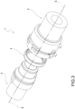
- a sealing bushing that is the object of the present invention is indicated overall with the numeral 4.
- the sealing bushing 4 is suitable for use in a connector 1 for the distribution of a fluid.
- the invention therefore also relates to a connector 1 that comprises the sealing bushing 4.
- the sealing bushing 4 extends about a bushing axis X-X.
- the connector 1 extends predominantly along a connector axis S-S.
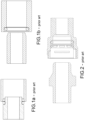
- the connector 1 has an "L" shape, that is, it has two portions substantially transverse to one another.
- the connector 1 comprises a female component 2, or cylinder, and a hollow male component 3, or piston, which, in an engagement configuration, engages the female component 2 to allow the fluid to pass.
- each component 2, 3 is made by molding.
- the female component 2 extends along a female axis Y-Y and the male component 3 extends along a male axis Z-Z.
- the connector axis S-S, the female axis Y-Y and the male axis Z-Z are coincident with respect to one another.
- the bushing axis X-X in the engagement configuration, that is, with the sealing bushing 4 housed in the connector 1, also coincides with said axes S-S, Y-Y and Z-Z.
- the female component 2 and the male component 3 are axisymmetric with respect to the relative Y-Y, Z-Z axes thereof.
- the female component 2 terminates with a female distal end 21; the male component 3 terminates with a male distal end 31.
- a bushing seat 24 suitable for receiving the sealing bushing 4 is obtained in an end portion of the female component 2.
- the bushing seat 24 is axisymmetric in relation to the bushing axis X-X.
- the sealing bushing 4 when inserted into the bushing seat 24, allows the sealing engagement between the male and female components 2, 3.
- the bushing seat 24 is delimited, at the opposite end thereof with respect to the female distal end 21, by an annular shoulder 50 which axially constrains the sealing bushing 4 in the insertion direction of the male component 3 into the female component 2.
- the connector 1 further comprises a matching ring 55 suitable for being fixed, for example by welding, to the end of the bushing seat 24 opposite the annular shoulder 50, in such a way as to prevent, during assembly operations or during use, the sealing bushing 4 from undergoing undesired axial displacements.
- the male component 3 is crossed axially by a male component duct 30; a female component duct 20 is obtained within the female component 2.
- the male component duct 30 is suitable for merging into the female component duct 20, so as to form a single fluidic duct 10 for the distribution of the fluid.
- the fluidic duct is delimited by an inner duct surface 12 and an outer duct surface 14.
- the annular shoulder 50 is made in the inner duct surface 12 of the female component 2. Therefore, with reference to Figure 4 , in the female component 2 the fluidic duct 12 comprises an end portion 12a, upstream of the annular shoulder 50, and a proximal portion 12b, downstream of the inner shoulder 50.
- the bushing seat 24 is delimited radially by a cylindrical inner surface 25.
- the annular shoulder 50 is obtained at a certain axial distance from the female distal end 21 of the female component 2. In one embodiment, said axial distance is at least equal to the axial dimension of the sealing bushing 4. In one embodiment, said axial distance is greater than the axial dimension of the sealing bushing 4, such that the latter is housed in a rearward position in relation to the female distal end 21.
- the sealing bushing 4 consists of a cylindrical body 40 which extends about the bushing axis X-X.
- the cylindrical body 40 defines an inner side surface 52 and an outer side surface 54.
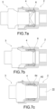
- the sealing bushing 4 in an assembly configuration of the connector 1, is inserted by shape and/or force coupling into the bushing seat 24. In some embodiments, the sealing bushing 4 is elastically deformed upon insertion into the bushing seat 24.
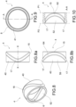
- the annular extension profile of the at least one annular rib 6 has at least one axial component parallel to the bushing axis X-X. In this way, the compression of the annular rib 6 during the insertion of the male component 3 into the sealing bushing 4 housed in the female component 2 takes place gradually.
- At least one section of the annular rib 6 has at least one component parallel to the bushing axis X-X.
- At least one section of the annular rib 6 is inclined in relation to an axis perpendicular to the bushing axis X-X.
- the annular rib 6 does not therefore lie in a single transverse plane in relation to the bushing axis X-X, as occurs in the case of O-rings of the prior art, but intersects multiple transverse planes.
- At least one section of the annular rib 6 is inclined both with respect to an axis perpendicular to the bushing axis X-X and to the bushing axis X-X itself.
- the male component 3 engages the annular rib 6 only in at least one point, preferably only in two diametrically opposite points.
- the annular extension profile of the annular rib 6 is shaped such that the compression of the annular rib 6 during the insertion of the male component 3 into the sealing bushing 4 grows linearly as a function of the penetration of the male component 3 into the sealing bushing 4.
- Figure 7b shows the connector 1 being assembled with the male component 3 in an intermediate position of partial engagement of the sealing bushing 4.
- Figure 7c shows the connector 1 assembled, with the male component 3 having reached the end-of-stroke position within the female component 2.
- the annular extension profile of the at least one annular rib 6 forms two semi-annular arcs 16.
- Each semi-annular arc 16 extends between two arc ends 17 diametrically opposed to each other and substantially tangent to one end of the bushing body 40.
- Each semi-annular arc 16 forms an arc curve 15 substantially tangent to the other end of the bushing body 40.
- the two semi-annular arches 16 are connected to each other at the arc ends 17.
- the arc curve 15 is tangent to an imaginary first plane P1 which is orthogonal to the bushing axis X-X and in which a first end of the cylindrical body 40 lies.
- the two arc ends 17 are tangent to a second imaginary plane P2 which is orthogonal to the bushing axis X-X and in which a second end of the cylindrical body 40 lies, opposite to the first.
- an inner annular rib 62 suitable for implementing a fluid seal with the outer surface 14 of the male component 3, is obtained only on the inner side surface 52.
- annular rib 62 is obtained on the inner side surface 52, which rib is suitable for creating a fluid seal with the outer surface 14 of the male component 3
- an outer annular rib 64 is obtained on the outer side surface 54, which rib is suitable for creating a fluid seal with the inner cylindrical surface 25 of the bushing seat 24.
- annular rib 62, 64 is obtained on both surfaces 52, 54.
- an outer annular rib 64 suitable for implementing a fluid seal with the inner cylindrical surface 25 of the bushing seat 24, is obtained only on the outer side surface 54.
- the outer annular rib 64 follows the same annular extension profile as the inner annular rib 62.
- the outer annular rib 64 is located at the inner annular rib 62, such that the outer annular rib 64 and inner annular rib 62 together form an annular sealing element 8 protruding, both internally and externally, from the side wall 41 of the cylindrical body 40.
- the sealing bushing 4 is provided with an inner annular rib 62 having a substantially circular cross-section.
- the sealing bushing 4 is provided with an outer annular rib 64 also having a substantially circular cross-section.
- Figures 11-13 show the sealing bushing 4 in many embodiment variants, wherein the inner annular rib 62 has a substantially lip-shaped cross-section.
- the lip-shaped cross-section of the inner annular rib 62 has a substantially flat annular wall 62', perpendicular to the bushing axis X-X, and an opposite curved wall 62", that is, convex.
- the annular rib 62 has substantially the same cross-section as the annular rib 62 of Figures 11 and 11a , but the sealing bushing 4 has a lower axial extension and a greater cylindrical body wall thickness. Consequently, the extension profile of the annular rib 62 has a less accentuated radius of curvature.
- the annular rib 62 has a more radially elongated but thinner lip-shaped cross-section. Furthermore, the annular rib 62 is connected to one end of the sealing bushing 4 by means of a curved annular wall 62", that is, convex, of greater thickness than the thickness of the remaining part of the side wall 41 of the cylindrical body 40.
- the sealing bushing 4 is made of a polymer material, for example rubber. Preferably, it is made in one piece, for example by molding.
- the sealing bushing that is the object of the present invention insofar as it allows for the distribution of the force exerted during assembly by reducing the assembly force required compared to known connectors, fully fulfills the determined purpose in overcoming the drawbacks mentioned with reference to the prior art.
- the connector that is the object of the present invention, as it comprises the sealing bushing also fully fulfills the intended purpose.
- the annular rib makes it possible to distribute the compression of the sealing bushing over a wider stroke, with a consequent reduction in the peak of the force required in order to assemble the connector.
- the extension profile of the annular rib allows for controlled deformation of the sealing bushing, so as to render the compression thereof less instantaneous, more progressive and less wasteful in terms of force.
- the sealing bushing makes it possible to reduce the amount of time necessary for the assembly of the connector.
- the sealing bushing ensures less fatigue for the workforce involved in assembling the connectors.
- the sealing bushing ensures high efficiency in terms of sealing.
- the sealing bushing is insertable into the bushing seat without the need for precise orientation.
- the connector components are easily molded, without presenting particular constructional complexities.
Landscapes
- Engineering & Computer Science (AREA)
- General Engineering & Computer Science (AREA)
- Mechanical Engineering (AREA)
- Gasket Seals (AREA)
Claims (14)
- Dichtungsbuchse (4) für einen Verbinder (1) zum Verteilen eines Fluids, wobei der Verbinder (1) umfasst:- eine weibliche bzw. aufnehmende Komponente (2), in der ein Buchsensitz (24) erhalten bzw. ausgebildet ist;- eine hohle männliche bzw. aufzunehmende Komponente (3), die in einer Eingriffskonfiguration in die aufnehmende Komponente (2) eingreift, um einen Durchgang des Fluids zu ermöglichen;wobei die Dichtungsbuchse (4) zum Einführen in den Buchsensitz (24) und zum Bereitstellen des Dichtungseingriffs zwischen der aufnehmenden Komponente (2) und der aufzunehmenden Komponente (3) geeignet ist;wobei die Dichtungsbuchse (4) dadurch gekennzeichnet ist, dass sie aus einem zylindrischen Körper (40) besteht, der sich um eine Buchsenachse (X-X) erstreckt, wobei zumindest eine ringförmige Rippe (6) zumindest an einer inneren Seitenfläche bzw. -oberfläche (52) oder äußeren Seitenfläche bzw. - oberfläche (54) des zylindrischen Körpers (40) erhalten bzw. ausgebildet ist, wobei die zumindest eine ringförmige Rippe (6) geeignet ist, eine Fluiddichtung mit einer äußeren Fläche bzw. Oberfläche (14) der aufzunehmenden Komponente (3) oder einer inneren Fläche bzw. Oberfläche (25) des Buchsensitzes (24) zu erzeugen, wobei das ringförmige Erstreckungsprofil der zumindest einen ringförmigen Rippe (6) zumindest eine axiale Komponente parallel zu der Buchsenachse (X-X) aufweist, so dass die Kompression der zumindest einen ringförmigen Rippe (6) beim Einführen der aufzunehmenden Komponente (3) in die Dichtungsbuchse (4), die in der aufnehmenden Komponente (2) untergebracht ist, allmählich erfolgt.
- Dichtungsbuchse (4) nach Anspruch 1, wobei das ringförmige Erstreckungsprofil der zumindest einen ringförmigen Rippe (6) so geformt ist, dass die Kompression der zumindest einen ringförmigen Rippe (6) beim Einführen der aufzunehmenden Komponente (3) in die Dichtungsbuchse (4), die in der aufnehmenden Komponente (2) untergebracht ist, linear als eine Funktion bzw. in Abhängigkeit des Eindringens der aufzunehmenden Komponente (3) in die Dichtungsbuchse (4) zunimmt.
- Dichtungsbuchse (4) nach Anspruch 1 oder 2, wobei das ringförmige Erstreckungsprofil der zumindest einen ringförmigen Rippe (6) zwei halbringförmige Bögen (16) bildet, wobei sich jeder halbringförmige Bogen (16) zwischen zwei Bogenenden (17) erstreckt, die einander diametral gegenüberliegen bzw. entgegengesetzt sind und im Wesentlichen tangential zu einem Ende des Buchsenkörpers (40) sind, wodurch eine Bogenkurve (15) im Wesentlichen tangential zu dem anderen Ende des Buchsenkörpers (40) gebildet ist.
- Dichtungsbuchse (4) nach einem der vorhergehenden Ansprüche, wobei eine innere ringförmige Rippe (62), die zum Erzeugen einer Fluiddichtung mit einer äußeren Fläche bzw. Oberfläche (14) der aufzunehmenden Komponente (3) geeignet ist, nur auf der inneren Seitenfläche (52) erhalten bzw. ausgebildet ist.
- Dichtungsbuchse (4) nach einem der Ansprüche 1 bis 3, wobei eine innere ringförmige Rippe (62), die zum Erzeugen einer Fluiddichtung mit einer äußeren Fläche bzw. Oberfläche (14) der aufzunehmenden Komponente (3) geeignet ist, auf der inneren Seitenfläche (52) erhalten bzw. ausgebildet ist, und eine äußere ringförmige Rippe (64), die zum Erzeugen einer Fluiddichtung mit der inneren Fläche (25) des Buchsensitzes (24) geeignet ist, auf der äußeren Seitenfläche (54) erhalten bzw. ausgebildet ist.
- Dichtungsbuchse (4) nach Anspruch 5, wobei die äußere ringförmige Rippe (64) demselben ringförmigen Erstreckungsprofil folgt wie die innere ringförmige Rippe (62).
- Dichtungsbuchse (4) nach Anspruch 5 oder 6, wobei die äußere ringförmige Rippe (64) mit der inneren ringförmigen Rippe (62) übereinstimmt, so dass die äußere ringförmige Rippe (64) und die innere ringförmige Rippe (62) zusammen ein ringförmiges Dichtungselement (8) bilden, das sowohl innen als auch außen von einer Seitenwand (41) des zylindrischen Körpers (40) vorsteht.
- Dichtungsbuchse (4) nach einem der vorhergehenden Ansprüche, wobei die zumindest eine ringförmige Rippe (6) einen im Wesentlichen kreisförmigen Abschnitt bzw. Querschnitt aufweist.
- Dichtungsbuchse (4) nach einem der Ansprüche 1 bis 7, wobei die zumindest eine ringförmige Rippe (6) einen lippenförmigen Abschnitt bzw. Querschnitt aufweist.
- Dichtungsbuchse (4) nach einem der vorhergehenden Ansprüche, hergestellt aus Polymermaterial, wie Gummi, und einstückig durch Formen.
- Verbinder (1) zum Verteilen eines Fluids, umfassend eine weibliche bzw. aufnehmende Komponente (2), eine hohle männliche bzw. aufzunehmende Komponente (3), die in einer Eingriffskonfiguration in die aufnehmende Komponente (2) eingreift, um einen Durchgang des Fluids zu ermöglichen, und eine Dichtungsbuchse (4) nach einem der vorhergehenden Ansprüche, die geeignet ist, dichtend in einem Buchsensitz (24) untergebracht zu sein, der in einem Endabschnitt der aufnehmenden Komponente (2) erhalten bzw. ausgebildet ist.
- Verbinder (1) nach Anspruch 11, wobei in einer Vormontagekonfiguration die Dichtungsbuchse (4) durch Form- und/oder Kraftkopplung in den Buchsensitz (24) eingeführt wird bzw. ist.
- Verbinder (1) nach Anspruch 11 oder 12, wobei der Buchsensitz (24) in Bezug auf die Buchsenachse (X-X) achsensymmetrisch ist.
- Verbinder (1) nach einem der Ansprüche 11 bis 13, wobei die Buchsenaufnahme (24) an einem Ende durch eine innere Schulter (50) begrenzt ist, die die Dichtungsbuchse (4) in der Einführrichtung der aufzunehmenden Komponente (3) in die aufnehmende Komponente (2) axial begrenzt.
Applications Claiming Priority (1)
| Application Number | Priority Date | Filing Date | Title |
|---|---|---|---|
| IT102022000005942A IT202200005942A1 (it) | 2022-03-25 | 2022-03-25 | Boccola di tenuta per connettore per la distribuzione di un fluido |
Publications (3)
| Publication Number | Publication Date |
|---|---|
| EP4249786A1 EP4249786A1 (de) | 2023-09-27 |
| EP4249786B1 true EP4249786B1 (de) | 2025-01-15 |
| EP4249786C0 EP4249786C0 (de) | 2025-01-15 |
Family
ID=82020056
Family Applications (1)
| Application Number | Title | Priority Date | Filing Date |
|---|---|---|---|
| EP23159314.6A Active EP4249786B1 (de) | 2022-03-25 | 2023-03-01 | Dichtungsbuchse für einen steckverbinder zur verteilung eines fluids |
Country Status (2)
| Country | Link |
|---|---|
| EP (1) | EP4249786B1 (de) |
| IT (1) | IT202200005942A1 (de) |
Families Citing this family (2)
| Publication number | Priority date | Publication date | Assignee | Title |
|---|---|---|---|---|
| NL2037187B1 (en) * | 2024-03-06 | 2025-09-15 | Wienerberger Ag | Pipe Coupler |
| NL2037188B1 (en) * | 2024-03-06 | 2025-09-19 | Wienerberger Ag | Pipe Coupler |
Citations (1)
| Publication number | Priority date | Publication date | Assignee | Title |
|---|---|---|---|---|
| US4440424A (en) * | 1978-06-02 | 1984-04-03 | Nycoil Corporation | Releasable coupling device |
Family Cites Families (3)
| Publication number | Priority date | Publication date | Assignee | Title |
|---|---|---|---|---|
| DE102005034567A1 (de) * | 2005-07-23 | 2007-02-01 | A. Raymond Et Cie | Kupplung |
| FR3082586B1 (fr) * | 2018-06-13 | 2020-05-22 | A. Raymond Et Cie | Embout femelle d'un raccord permettant l'insertion d'un embout male avec un effort reduit |
| DE202020105671U1 (de) * | 2020-10-02 | 2020-10-13 | TI Automotive (Fuldabrück) GmbH | Verbinder zum Verbinden zweier fluidführender Elemente |
-
2022
- 2022-03-25 IT IT102022000005942A patent/IT202200005942A1/it unknown
-
2023
- 2023-03-01 EP EP23159314.6A patent/EP4249786B1/de active Active
Patent Citations (1)
| Publication number | Priority date | Publication date | Assignee | Title |
|---|---|---|---|---|
| US4440424A (en) * | 1978-06-02 | 1984-04-03 | Nycoil Corporation | Releasable coupling device |
Also Published As
| Publication number | Publication date |
|---|---|
| EP4249786A1 (de) | 2023-09-27 |
| IT202200005942A1 (it) | 2023-09-25 |
| EP4249786C0 (de) | 2025-01-15 |
Similar Documents
| Publication | Publication Date | Title |
|---|---|---|
| EP4249786B1 (de) | Dichtungsbuchse für einen steckverbinder zur verteilung eines fluids | |
| EP1378701B1 (de) | Schnellverbindung zum Verbinden von zwei Rohrenden | |
| EP1579142B1 (de) | Kupplungsanordnung mit profilrampe | |
| US6439617B1 (en) | Coupler for a pipe or hose section | |
| US8104512B2 (en) | Spout tip retention method | |
| EP2867516B1 (de) | Kraftstoffleitungsverbinder | |
| US7963571B2 (en) | Tubing configuration and sealing method for high pressure tubing on high pressure fuel systems | |
| EP3584489B1 (de) | Kupplungsanordnung und verbinder für eine kupplungsanordnung | |
| CN100386556C (zh) | 阴连接器部件以及配备有这种部件的快速连接器 | |
| US20080284108A1 (en) | Seal | |
| US6764104B2 (en) | Line connector, in particular for fuel lines | |
| US7789397B2 (en) | Metallic seal | |
| EP1711734B1 (de) | Kupplungsanordnung | |
| US20080036207A1 (en) | Connector of Flexible Pipe | |
| EP1055860A2 (de) | Rohrverbindung | |
| TWI289638B (en) | Valve holding member | |
| CN113795696B (zh) | 用于连接管道、特别是用于连接柔性管道的配件 | |
| EP3533991B1 (de) | Kraftstoffleitung | |
| MX2009001316A (es) | Acoplamiento macho para conectarse a un acoplamiento hembra roscado. | |
| CN118836317A (zh) | 一种用于卡压连接结构的高抗拔性能的卡圈 | |
| GB2581359A (en) | Common rail for gasoline engine | |
| EP3267086A1 (de) | Kupplungsanordnung, verbinder für eine kupplungsanordnung und leitung mit einer kupplungsanordnung | |
| CN103938675A (zh) | 卫生配件用于该卫生配件的流体导管 | |
| DE102018212593A1 (de) | Fluidverbindungsadapter, Fluidverbindungsanordnung sowie Verfahren zum Herstellen eines Fluidverbindungsadapters | |
| CN219796501U (zh) | 快接管件 |
Legal Events
| Date | Code | Title | Description |
|---|---|---|---|
| PUAI | Public reference made under article 153(3) epc to a published international application that has entered the european phase |
Free format text: ORIGINAL CODE: 0009012 |
|
| STAA | Information on the status of an ep patent application or granted ep patent |
Free format text: STATUS: THE APPLICATION HAS BEEN PUBLISHED |
|
| AK | Designated contracting states |
Kind code of ref document: A1 Designated state(s): AL AT BE BG CH CY CZ DE DK EE ES FI FR GB GR HR HU IE IS IT LI LT LU LV MC ME MK MT NL NO PL PT RO RS SE SI SK SM TR |
|
| STAA | Information on the status of an ep patent application or granted ep patent |
Free format text: STATUS: REQUEST FOR EXAMINATION WAS MADE |
|
| 17P | Request for examination filed |
Effective date: 20240326 |
|
| RBV | Designated contracting states (corrected) |
Designated state(s): AL AT BE BG CH CY CZ DE DK EE ES FI FR GB GR HR HU IE IS IT LI LT LU LV MC ME MK MT NL NO PL PT RO RS SE SI SK SM TR |
|
| GRAP | Despatch of communication of intention to grant a patent |
Free format text: ORIGINAL CODE: EPIDOSNIGR1 |
|
| STAA | Information on the status of an ep patent application or granted ep patent |
Free format text: STATUS: GRANT OF PATENT IS INTENDED |
|
| RIC1 | Information provided on ipc code assigned before grant |
Ipc: F16L 21/03 20060101ALN20240718BHEP Ipc: F16L 37/088 20060101ALI20240718BHEP Ipc: F16L 37/091 20060101AFI20240718BHEP |
|
| INTG | Intention to grant announced |
Effective date: 20240802 |
|
| RIC1 | Information provided on ipc code assigned before grant |
Ipc: F16L 21/03 20060101ALN20240726BHEP Ipc: F16L 37/088 20060101ALI20240726BHEP Ipc: F16L 37/091 20060101AFI20240726BHEP |
|
| GRAS | Grant fee paid |
Free format text: ORIGINAL CODE: EPIDOSNIGR3 |
|
| GRAA | (expected) grant |
Free format text: ORIGINAL CODE: 0009210 |
|
| STAA | Information on the status of an ep patent application or granted ep patent |
Free format text: STATUS: THE PATENT HAS BEEN GRANTED |
|
| AK | Designated contracting states |
Kind code of ref document: B1 Designated state(s): AL AT BE BG CH CY CZ DE DK EE ES FI FR GB GR HR HU IE IS IT LI LT LU LV MC ME MK MT NL NO PL PT RO RS SE SI SK SM TR |
|
| REG | Reference to a national code |
Ref country code: CH Ref legal event code: EP Ref country code: GB Ref legal event code: FG4D |
|
| REG | Reference to a national code |
Ref country code: DE Ref legal event code: R096 Ref document number: 602023001622 Country of ref document: DE |
|
| REG | Reference to a national code |
Ref country code: IE Ref legal event code: FG4D |
|
| U01 | Request for unitary effect filed |
Effective date: 20250129 |
|
| U07 | Unitary effect registered |
Designated state(s): AT BE BG DE DK EE FI FR IT LT LU LV MT NL PT RO SE SI Effective date: 20250205 |
|
| U20 | Renewal fee for the european patent with unitary effect paid |
Year of fee payment: 3 Effective date: 20250224 |
|
| PG25 | Lapsed in a contracting state [announced via postgrant information from national office to epo] |
Ref country code: RS Free format text: LAPSE BECAUSE OF FAILURE TO SUBMIT A TRANSLATION OF THE DESCRIPTION OR TO PAY THE FEE WITHIN THE PRESCRIBED TIME-LIMIT Effective date: 20250415 |
|
| PG25 | Lapsed in a contracting state [announced via postgrant information from national office to epo] |
Ref country code: PL Free format text: LAPSE BECAUSE OF FAILURE TO SUBMIT A TRANSLATION OF THE DESCRIPTION OR TO PAY THE FEE WITHIN THE PRESCRIBED TIME-LIMIT Effective date: 20250115 |
|
| PG25 | Lapsed in a contracting state [announced via postgrant information from national office to epo] |
Ref country code: ES Free format text: LAPSE BECAUSE OF FAILURE TO SUBMIT A TRANSLATION OF THE DESCRIPTION OR TO PAY THE FEE WITHIN THE PRESCRIBED TIME-LIMIT Effective date: 20250115 |
|
| PG25 | Lapsed in a contracting state [announced via postgrant information from national office to epo] |
Ref country code: IS Free format text: LAPSE BECAUSE OF FAILURE TO SUBMIT A TRANSLATION OF THE DESCRIPTION OR TO PAY THE FEE WITHIN THE PRESCRIBED TIME-LIMIT Effective date: 20250515 Ref country code: NO Free format text: LAPSE BECAUSE OF FAILURE TO SUBMIT A TRANSLATION OF THE DESCRIPTION OR TO PAY THE FEE WITHIN THE PRESCRIBED TIME-LIMIT Effective date: 20250415 |
|
| PG25 | Lapsed in a contracting state [announced via postgrant information from national office to epo] |
Ref country code: HR Free format text: LAPSE BECAUSE OF FAILURE TO SUBMIT A TRANSLATION OF THE DESCRIPTION OR TO PAY THE FEE WITHIN THE PRESCRIBED TIME-LIMIT Effective date: 20250115 |
|
| PG25 | Lapsed in a contracting state [announced via postgrant information from national office to epo] |
Ref country code: GR Free format text: LAPSE BECAUSE OF FAILURE TO SUBMIT A TRANSLATION OF THE DESCRIPTION OR TO PAY THE FEE WITHIN THE PRESCRIBED TIME-LIMIT Effective date: 20250416 |
|
| PGFP | Annual fee paid to national office [announced via postgrant information from national office to epo] |
Ref country code: IE Payment date: 20250528 Year of fee payment: 3 |
|
| PG25 | Lapsed in a contracting state [announced via postgrant information from national office to epo] |
Ref country code: SM Free format text: LAPSE BECAUSE OF FAILURE TO SUBMIT A TRANSLATION OF THE DESCRIPTION OR TO PAY THE FEE WITHIN THE PRESCRIBED TIME-LIMIT Effective date: 20250115 |
|
| PG25 | Lapsed in a contracting state [announced via postgrant information from national office to epo] |
Ref country code: MC Free format text: LAPSE BECAUSE OF FAILURE TO SUBMIT A TRANSLATION OF THE DESCRIPTION OR TO PAY THE FEE WITHIN THE PRESCRIBED TIME-LIMIT Effective date: 20250115 |
|
| PG25 | Lapsed in a contracting state [announced via postgrant information from national office to epo] |
Ref country code: CZ Free format text: LAPSE BECAUSE OF FAILURE TO SUBMIT A TRANSLATION OF THE DESCRIPTION OR TO PAY THE FEE WITHIN THE PRESCRIBED TIME-LIMIT Effective date: 20250115 |
|
| PG25 | Lapsed in a contracting state [announced via postgrant information from national office to epo] |
Ref country code: SK Free format text: LAPSE BECAUSE OF FAILURE TO SUBMIT A TRANSLATION OF THE DESCRIPTION OR TO PAY THE FEE WITHIN THE PRESCRIBED TIME-LIMIT Effective date: 20250115 |
|
| PLBE | No opposition filed within time limit |
Free format text: ORIGINAL CODE: 0009261 |
|
| STAA | Information on the status of an ep patent application or granted ep patent |
Free format text: STATUS: NO OPPOSITION FILED WITHIN TIME LIMIT |
|
| 26N | No opposition filed |
Effective date: 20251016 |