EP1579142B1 - Kupplungsanordnung mit profilrampe - Google Patents
Kupplungsanordnung mit profilrampe Download PDFInfo
- Publication number
- EP1579142B1 EP1579142B1 EP03791077.5A EP03791077A EP1579142B1 EP 1579142 B1 EP1579142 B1 EP 1579142B1 EP 03791077 A EP03791077 A EP 03791077A EP 1579142 B1 EP1579142 B1 EP 1579142B1
- Authority
- EP
- European Patent Office
- Prior art keywords
- exterior surface
- cylindrical
- ramp
- male member
- shoulder
- Prior art date
- Legal status (The legal status is an assumption and is not a legal conclusion. Google has not performed a legal analysis and makes no representation as to the accuracy of the status listed.)
- Expired - Lifetime
Links
- 230000008878 coupling Effects 0.000 title claims abstract description 26
- 238000010168 coupling process Methods 0.000 title claims abstract description 26
- 238000005859 coupling reaction Methods 0.000 title claims abstract description 26
- 239000002184 metal Substances 0.000 abstract description 20
- 229910052751 metal Inorganic materials 0.000 abstract description 20
- 230000037431 insertion Effects 0.000 abstract description 10
- 238000003780 insertion Methods 0.000 abstract description 10
- 238000006073 displacement reaction Methods 0.000 description 12
- 239000012530 fluid Substances 0.000 description 7
- 239000004033 plastic Substances 0.000 description 5
- 229920003023 plastic Polymers 0.000 description 5
- 239000000428 dust Substances 0.000 description 4
- 229910000831 Steel Inorganic materials 0.000 description 3
- 239000000203 mixture Substances 0.000 description 3
- 238000007789 sealing Methods 0.000 description 3
- 239000010959 steel Substances 0.000 description 3
- XEEYBQQBJWHFJM-UHFFFAOYSA-N Iron Chemical compound [Fe] XEEYBQQBJWHFJM-UHFFFAOYSA-N 0.000 description 2
- 238000004519 manufacturing process Methods 0.000 description 2
- 230000000717 retained effect Effects 0.000 description 2
- 229910000906 Bronze Inorganic materials 0.000 description 1
- 239000010974 bronze Substances 0.000 description 1
- 239000000356 contaminant Substances 0.000 description 1
- KUNSUQLRTQLHQQ-UHFFFAOYSA-N copper tin Chemical compound [Cu].[Sn] KUNSUQLRTQLHQQ-UHFFFAOYSA-N 0.000 description 1
- 230000007423 decrease Effects 0.000 description 1
- 230000000694 effects Effects 0.000 description 1
- 239000013536 elastomeric material Substances 0.000 description 1
- 230000002349 favourable effect Effects 0.000 description 1
- 229910052742 iron Inorganic materials 0.000 description 1
- 239000000463 material Substances 0.000 description 1
- 238000000465 moulding Methods 0.000 description 1
- 229920001084 poly(chloroprene) Polymers 0.000 description 1
- 239000003566 sealing material Substances 0.000 description 1
- 229910001220 stainless steel Inorganic materials 0.000 description 1
- 239000010935 stainless steel Substances 0.000 description 1
- 229920001169 thermoplastic Polymers 0.000 description 1
- 239000004416 thermosoftening plastic Substances 0.000 description 1
Images


Classifications
-
- F—MECHANICAL ENGINEERING; LIGHTING; HEATING; WEAPONS; BLASTING
- F16—ENGINEERING ELEMENTS AND UNITS; GENERAL MEASURES FOR PRODUCING AND MAINTAINING EFFECTIVE FUNCTIONING OF MACHINES OR INSTALLATIONS; THERMAL INSULATION IN GENERAL
- F16L—PIPES; JOINTS OR FITTINGS FOR PIPES; SUPPORTS FOR PIPES, CABLES OR PROTECTIVE TUBING; MEANS FOR THERMAL INSULATION IN GENERAL
- F16L37/00—Couplings of the quick-acting type
- F16L37/08—Couplings of the quick-acting type in which the connection between abutting or axially overlapping ends is maintained by locking members
- F16L37/084—Couplings of the quick-acting type in which the connection between abutting or axially overlapping ends is maintained by locking members combined with automatic locking
- F16L37/088—Couplings of the quick-acting type in which the connection between abutting or axially overlapping ends is maintained by locking members combined with automatic locking by means of a split elastic ring
- F16L37/0887—Couplings of the quick-acting type in which the connection between abutting or axially overlapping ends is maintained by locking members combined with automatic locking by means of a split elastic ring with an axially movable separate member for releasing the coupling
Definitions
- the present invention relates to push-to-connect fluid connectors and more specifically the present invention relates to push-to-connect fluid connectors which use a latch ring where the ridge of the male connector has been modified to incorporate a profiled curved ramp for ease of connection.
- the present invention reduces the maximum force required to connect a male connector to a female connector to complete a push-to-connect type of fluid connection system.
- the profile of the male connection is altered to reduce the maximum force required to push a latch ring up the ramp, over the apex and onto a shoulder.
- the latch ring is retained and concurrently contacts the shoulder of the male connector and the chamfer on the female connector so as to retain the male to the female.
- One or more curved radius sections are introduced to the ridge on the male connector which serves to reduce the maximum force required to push the latch ring into place when connecting the male to the female connector.
- a curved ramp of the ridge includes at least a curved or radiused portion to provide the desired force to connect verses displacement curve to enhance connectability of the system.
- One alternate embodiment does not include a flat section while incorporating the radiused ramp and the shoulder section.
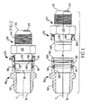
- FIG. 1 is a cross-sectional view of the fluid connection system of the present invention
- FIG. 2 is a cross-sectional view of the male connector of the present invention in partial engagement with a female connector
- FIG. 3 is a cross-sectional view of the male connector of the present invention and a female connector
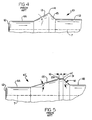
- FIG. 4 is a partial perspective view of a first prior art male connector
- FIG. 5 is a partial cross-sectional view of a second prior art male connector
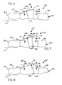
- FIG. 6 is a partial cross-sectional view of a first embodiment of the male coupling of the present invention.
- FIG. 7 is a partial cross-sectional view of a second embodiment of the male coupling of the present invention.
- FIG. 8 is a partial cross-sectional view of a third embodiment of the male coupling of the present invention.
- FIG. 8A is a partial cross-sectional view of a fourth embodiment of the male coupling of the present invention.
- FIG. 9 is a partial cross-sectional view of a fifth embodiment of the male coupling of the present invention.
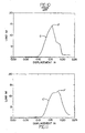
- FIG. 10 is a connection force verses displacement graph of a prior art fluid connection system
- FIG. 11 is a connection force verses displacement graph of the connection system of the present invention.
- FIG. 12 is a connection force verses displacement graph of the connection system of the third embodiment of the present invention.
- forward and rearward will refer to directions forward and rearward of the coupling as shown in the drawings.
- rightward and leftward will refer to directions in the drawings in connection with which the terminology is used.
- inwardly and outwardly will refer to directions toward and away from, respectively, the geometric center of the apparatus.
- upward and downward will refer to directions as taken in the drawings in connection with which the terminology is used. All foregoing terms mentioned above include the normal derivatives and equivalents thereof.
- the coupling assembly of the present invention includes a male member 20 and a female member 30.
- Each of the male member 20 and female member 30 extends along an axis 7 when the assembly is in the coupled position as shown in FIGS. 1 and 2 .
- the male member 20 extends from a leading end 21 intended for insertion in the female member 30 to a trailing end 22 and has a passageway 23 extending therethrough.
- the trailing end 22 may be provided with external threads 24 for attachment to a threaded coupling (not shown) and a series of flats 25 defining a hexagonal cross section for engagement by a wrench.
- the male member 20 Forwardly of the hexagonal cross section defined by the flats 25, the male member 20 has a trailing cylindrical exterior surface 26 and a leading exterior surface 27 which are separated by a rib.
- the rib includes a tapered radiused ramp 28 extending rearwardly and outwardly from the leading exterior surface 27 at an angle Y relative to the axis 7 in the range of 10 degrees to 25 degrees and preferably at an angle of 18 degrees (see FIG. 5 ).
- the ramp 28" extends to a cylindrical surface 29 which is paralle to the axis and extends rearwardly from the ramp 28" a distance A of at least 0.254 mm (0.010 inch) and, preferably at least 0.762 mm (0.030 inch).
- the final portion of the rib is a shoulder 31 which tapers rearwardly and inwardly from said cylindrical surface 29 to meet said trailing exterior surface 26.
- the shoulder 31 should taper at an angle M in the range of 35° to 55° relative to the axis 7 and preferably at an angle of about 45° (see FIG. 5 ).
- FIG. 1 a cross-sectional view of another component of the male member 20, a separately formed release sleeve 33 consisting of a metal portion 34 and a thermoplastic and/or elastomeric (TPE) portion 35 is shown.
- the metal portion 34 includes a split cylindrical wall 36 having a plurality of axial slots.
- the TPE portion 35 may be molded around the flange 42 and includes a flange portion 44 and a cylindrical wall portion 45 spaced from and substantially parallel to the split cylindrical wall 36 of the metal portion 34.
- the TPE portion 35 includes a sealing fin 47 extending radially inwardly from the flange portion 44.
- the sealing fin 47 extends inwardly sufficiently for to snugly engage the trailing cylindrical exterior surface 26 to thereby function as a dust seal to prevent dust from, or at least minimize the possibility of dust, entering the engaged coupling between the release sleeve 33 and the trailing exterior surface 26. See US 2002/019350 and US 2002/0109351 for an alternate embodiment for the release sleeve 33.
- the second female member 30 extends from a receiving end 50 to a remote end 51 which may have adjacent thereto external threads 52 or other suitable connection means for fastening to a separate connection (not shown).
- the portion of the second female member 30 adjacent the receiving end 50 is provided with an exterior cylindrical surface 52 having a size to be snugly received in the cylindrical wall 45 of the release sleeve 33 and an interior cylindrical surface 53 sized to receive therein the split cylindrical wall portion 36 of the metal portion 34 of release sleeve 33.
- An inwardly facing annular groove 54 extends outwardly from the interior cylindrical surface 53 and is sized to receive therein a split metal locking ring 60.
- a chamfer 55 extends at an angle inwardly from the annular groove 54 toward the receiving end 50 to meet the interior cylindrical surface 53.
- the angle N (see FIG. 5 ) between the chamfer 55 and the interior cylindrical surface 53 is in the range of 20° to 40° and is preferably 30°.
- a second interior cylindrical surface 56 of smaller size than the first cylindrical surface 53 is positioned toward the remote end 51 from the annular groove 54 and is joined thereto by an inwardly tapering wall portion 57.
- the second interior cylindrical surface 56 is sized to receive the leading exterior surface 27 of the first male member 20.
- the second interior cylindrical wall surface 56 has formed therein an inwardly facing annular groove 58 in which is positioned an annular seal 59 of neoprene or other suitable sealing material and a rigid plastic ring 61 which is positioned in the groove 58 between the annular seal 59 and the receiving end 50.
- the plastic ring 61 has an aperture sized to snugly receiving the leading exterior surface 27 of the first male member and the annular seal 59 is sized to sealingly receive and engage such leading exterior surface 27.
- the presence of the rigid plastic ring 61 in a position to be engaged by the leading end 21 of the first male member 20 serves to protect the annular seal 59 from cutting or other damage upon insertion of the leading exterior surface 27 therethrough.
- the rigid plastic ring 61 also serves to protect the annular seal 59 from damage when used in systems having high impulse flow of fluid.
- a split metal locking ring 60 Positioned in the annular groove 54 is a split metal locking ring 60 formed of a spring tempered phosphoric bronze material or, preferably, a spring tempered stainless steel.
- the split locking ring 60 is provided with a first end and a second end which should either be in abutting relationship or have a typical gap of 0.030 inch when the first male member 20 is disconnected from the second female member 30.
- the split locking ring 60 when the parts are in the disconnected position, has an external diameter smaller than the diameter defined by the outermost portion of the annular groove 54 but larger than the diameter of the first interior cylindrical surface 53.
- the split locking ring 60 has an internal diameter substantially equal to or, preferably, slightly smaller than that of the trailing exterior surface 26 of the male member 20 to snugly engage such trailing exterior surface 26 when the male member 20 is engaged to the female member 30.
- the internal diameter of the split locking ring 60 is therefore, significantly smaller than the diameter of the cylindrical surface 29.
- the split locking ring 60 by virtue of its dimensions, will be retained in the annular groove 54 when the first male member 20 is disconnected from the second female member 21. However, by virtue of its being split, the diametrical size of the locking ring 60 may be expanded and the end portions become separated as the locking ring 60 moves over the ramp 28" and cylindrical surface 29 upon insertion of the first male member 20 into the second female member 30.
- the split locking ring 60 As the cylindrical surface 29 moves past the split locking ring 60 upon continued forward movement of the first male member 20, the split locking ring 60, by virtue of the resilience of the metal will contract to a size approaching its original size and, in do so, will be positioned to prevent withdrawal of the first male member 20 from the second female member 30 by virtue of the split locking ring 60 being trapped between the shoulder 31 and the chamfer 55 formed in the female member 30.
- the tapered shoulder 31 and the chamfer 55 are disposed at converging angles in the direction toward the annular groove 54 when the first male member 20 is engaged to the female member 30. This convergence results from the fact that the angle of the tapered shoulder 31 is greater than the angle of the chamfer 55 in relation to the axis 7 as previously set forth.
- the leading exterior surface 27 is sealingly engaged to the annular seal 59 thereby preventing leaking of fluid.
- receiving end 50 and portions of the second female member adjacent thereto are positioned in the gap 46 between the cylindrical wall portion 45 of the TPE portion 35 and the split cylindrical wall 36 of the metal portion.
- the exterior cylindrical surface 52 is snugly in contact with the interior of the cylindrical wall portion 45 thereby preventing, along with the sealing fin 47, dust or other contaminants from the entering the area around the split metal locking ring 60 when the members are in the engaged position of FIG. 1 .
- the release sleeve 33 has a split cylindrical wall 36 with slots 37, the segments of the split cylindrical wall 36 between the slots 37 can be deflected outwardly by the tapered shoulder 31 thereby ensuring that the release sleeve 33 can be moved far enough toward the leading end 21 to ensure that it forces the split metal locking ring 60 out of engagement with the tapered shoulder 31 and into the annular groove 54 as it engages the cylindrical surface 29 thereby permitting release of the male member 20 from the female member.
- the portion of the release sleeve split cylindrical wall 36 adjacent the leading end 38 may be deflected outwardly by the movement of the leading end 38 against the tapered shoulder 31.
- Prior art couplings of the type utilizing a rib and a split metal lock ring which have been tested withstand pressures of four times the specified Operating Pressure for the SAE 100R2 Standards but not for the DIN Type 2ST Standards.
- the coupling assembly of the present invention is capable of withstanding pressures of four times the specified Operating Pressures for both the SAE 100R2 Standards and the DIN Type 2ST Standards.
- FIG. 4 a partial cross-sectional view of a prior art male member 10 is shown.
- This embodiment is disclosed in U.S. Pat. Nos. 5,226,682 and 5,553,895 and includes a ramp 13 which uniformly increases at angle X in axial distance from centerline 17 along the leading exterior surface 11A to reach an apex 14.
- a shoulder 15 then joins the apex 14 to the trailing exterior surface 11 B.
- the leading end 12 is inserted into a female coupling.
- FIG. 5 is a partial cross-sectional view of a prior art male member 20 as disclosed in U.S. Pat. No. 5,553,895 in FIG. 2 of that patent.
- the male member 10' Forwardly, of the hexagonal cross section defined by the flats 25, the male member 10' has a trailing cylindrical exterior surface 11 B and a leading exterior surface 11A which are separated by a rib.
- the rib or ridge includes a tapered ramp 13' extending rearwardly and outwardly from the leading exterior surface 11A at an angle X' relative to the axis 7 in the range of 10° to 25° and preferably at an angle of 18°.
- the ramp 13' extends to a cylindrical surface or flat 29 which is parallel to the axis and extends rearwardly from the ramp 13' a distance A of at least 0.254 mm (0.010 inch) and, preferably at least 0.762 mm (0.030 inch).
- the final portion of the rib is a shoulder 31 which tapers rearwardly and inwardly from said cylindrical surface 29 to meet said trailing exterior surface 11 B.
- the shoulder 31 should taper at an angle M in the range of 35° to 55° relative to the axis 7 and preferably at an angle of about 45°.
- FIG. 6 a first embodiment of the elevational view of the male member 20' of the present invention is shown.
- the male member 20' extends from a leading end 21 to a trailing end 23 as shown in FIG. 1 .
- the male member 20' has a trailing cylindrical exterior surface 26 and a leading cylindrical exterior surface 27 which are separated by a ridge or rib 15'.
- the leading end 21 is intended to be inserted into the female member 30.
- the rib 15' is comprised of a ramp 28' beginning at break point 22 and extending rearwardly (to the right) and outwardly from the leading exterior surface 27 at a curved angle. Shown in FIG. 6 for reference purposes is angle Y relative to the axis 7 which can vary along with the angle of the ramp 28' in the range of 10° to approximately 25°, preferably at an angle Y of 18°. According to the present invention, the profile of the ramp 28' has been changed from a uniform, straight, cone-like surface to an outwardly curved surface. A section of a circle having radius R' describes the approximate profile of the ramp 28' in the first embodiment of the present invention extending from the leading exterior surface 27 to the apex 14 of the ramp 28'.
- the curved outer surface of the ramp 28' need not be a section of a circle with radius R' but could be varied in curvature to yield the desired force verses displacement curve for the split locking ring 60 or other more complicated shapes could be utilized.
- the rib 15' of the first embodiment of the present invention provides a more desired force/displacement curve for the split metal locking ring 60 as it traverses the rib 28' upon insertion of the male member 20' into the female member 30.
- FIG. 7 an elevational view of a second embodiment of the male member 20" of the present invention is shown.
- the male member 20" extends from a leading end 21' to a trailing end 23 as shown in FIG. 7 .
- the male member 20" has a trailing cylindrical exterior surface 26 and a leading cylindrical exterior surface 27 which are separated by a ridge or rib 15".
- the leading end 21 is intended to be inserted into the female member 30.
- the rib 15" is comprised of a ramp 28" extending rearwardly (to the right) and outwardly from the leading exterior surface 27.
- a flat 29 of width A' extends from the end of the ramp 28" at point 16 to the apex 14' of shoulder 31.
- the surface of the flat 29 extends approximately parallel to the axis 7 of the male member 20".
- the shoulder 31 is at an angle of M with the axis 7 of the male member 20" while the dotted line 19 from break point 22 to point 16 is at an angle Y of approximately in the range of 10° through 25° with a preferred value of 18°.
- the actual surface ramp 28" is radiused to extend outwardly from dotted line 19 and is shown shaped as a section of a circle with radius R" and intersecting at break point 22 and point 16. Radius R" is selected so that the maximum height of the ramp 28" does not exceed the height of the flat 29 above the axis 7 of the male member 20".
- FIG. 8 of the drawings a cross-sectional view of a third embodiment of the male member 20'" of the present invention is shown.
- the male member 20'" extends from a leading end 21 to a trailing end 23 as shown in FIG. 8 .
- the male member 20"' has a trailing cylindrical exterior surface 26 and a leading cylindrical exterior surface 27 which are separated by a rib 15"'.
- the leading end 21 is intended to be inserted into the female member 30.
- the rib 15'" is comprised of a ramp 28'" extending rearwardly (to the right) to point 17 and outwardly from the leading exterior surface 27.
- the shoulder 31 is at an angle of M with the axis 7 of the male member 20"'.
- the ramp 28"' extends at a direct straight line from break point 22 to point 17 at an angle Y from the axis 7 although the ramp 28"' could extend in other shapes as well such as a curved shape.
- a radiused section having a radius R'" extends from point 17 to apex 14' and defines a radiused section 9. Radius R"' is chosen such that the maximum height of the ramp 28'" does not exceed the maximum height of the flat 29 from the axis 7 blends the ramp 28"' to the apex 14' and yields the desired insertion force verses displacement curve.
- FIG. 8A of the drawings a cross-sectional view of a fourth embodiment of the male member 20"" of the present invention is shown.
- the male member 20"" is similar to the male member 20'" shown in FIG. 8 except a flat 29' (flat) of width A" of approximately 0.254 mm (0.010 inch) joins the radiused section 19' extending from point 17 to point 16' to the apex 14'.
- the radiused section 19' as defined extending from point 17 to point 16' has a radius of R"" and blends in to join the ramp 28"' to the cylindrical surface 29'.
- the male member 20"' extends from a leading end 21 to a trailing end 23 as shown in FIG. 8A .
- the male member 20'" has a trailing cylindrical exterior surface 26 and a leading cylindrical exterior surface 27 which are separated by a ridge or rib 15"".
- the leading end 21 is intended to be inserted into the female member 30.
- the rib 15"" is comprised of a ramp 28'" beginning at break point 22 and extending rearwardly (to the right) and extending in outwardly from the leading exterior surface 27.
- the ramp 28"' is connected to the apex 14' via first a radiused section 19' extending from point 17 to point 16' and then a cylindrical section or flat 29'.
- the ramp 28'" extends at a direct straight line from break point 22 to point 17 at an angle Y from the axis 7.
- the ramp 28'" could also extend in other shapes such as a radiused cross-sectional shape or other curved or multiple straight line shapes.
- the radius R"" is chosen to provide a blend between the ramp 28'" and the flat 29'.
- the combination of the ramp 28"', the radiused section 9' and the flat 29' combine to determine the characteristic of the insertion force as the male member 20'" is inserted into the female member 30.
- FIG. 9 of the drawings a partial cross-sectional view of a fourth embodiment of the male member 20""' of the present invention is shown.
- the male member 20""' extends from a leading end 21 to a trailing end 23 as shown in FIG. 9 .
- the male member 20""' has a trailing cylindrical exterior surface 26 and a leading cylindrical exterior surface 27 which are separated by a rib 15""'.
- the leading end 21 is intended to be inserted into the female member 30.
- the rib 15""' is comprised of a ramp 28"" extending rearwardly (to the right) and outwardly from the leading exterior surface 27 at an angle of Z as opposed to angle Y as shown in FIG. 8 .
- the ramp 28"" is shown as a relatively straight line extending from the break point 22 to the point 17' but could be slightly curved outwardly from the axis 7. From point 17' to apex 14', a outwardly extending curve is formed with a radius R""' having a maximum distance from the axis 7 at point 40. The radial distance of point 40 from the axis 7 is greater than the radial distance of the apex 14' from the axis 7. This increased distance results in a favorable load verses displacement curve as shown in FIG. 12 for this fourth alternate embodiment. The locking ring 60 becomes trapped between the shoulder 31 and the chamfer 55 as previously described.
- FIG. 10 a graph of insertion force in pounds force verses displacement in inches for a typical prior art connector system such as that disclosed in U.S. Pat. No. 5,553,895 is shown.
- the male member 20 requires a minimum force (Ib f ) to engage the female member 30 and complete the connection.
- Ib f minimum force
- This can be graphically represented in the graph shown in FIG. 10 for the prior art coupling where the curve C reaches a peak level of force of 62.3 N (14 lb f ) at point P at approximately 3.81 mm (0.15 inch) from the start of the ramp 28.
- FIG. 11 shows a graph of projected data for the insertion force in pounds force verses displacement in inches for the first three embodiments of the coupling of the present invention.
- FIG. 11 is a typical result as the male member 20 is inserted into the female member 30.
- Curve C' increases in a manner similar to the curve C initially while the peak force P' of the coupling of the present invention is significantly lower at 53.4 N (12 lb f ). This results in a connection that is more easily made by an assembly person.
- FIG. 12 of the drawings a graphical representation of the load required to connect the male member 20"" into the female member 30 is shown.
- FIG. 12 is projected data for the shape of the male member 20"" shown in FIG. 9 .
- the load verses displacement graph shown in FIG. 11 applies generally to the male members shown in FIGS. 6 through 8 .
- FIG. 12 shows that the load curve C" increases at a fairly rapid rate as the locking ring 60 engages and travels up the ramp 28"" to point 17 and reaches a peak value P" of approximately 66.7 N (15 lb f ) an then rapidly decreases as the locking ring 60 reaches point 40 on the male member 20"".
- P peak value
Landscapes
- Engineering & Computer Science (AREA)
- General Engineering & Computer Science (AREA)
- Mechanical Engineering (AREA)
- Quick-Acting Or Multi-Walled Pipe Joints (AREA)
Claims (5)
- Kupplungsanordnung mit einer Achse (7), die aufweist:(a) ein Steckerteil (20), das sich von einem vorderen Ende (21) zu einem hinteren Ende (22) erstreckt, eine erste zylindrische Außenfläche (27), die sich von dem vorderen Ende (21) aus erstreckt, eine zweite zylindrische Außenfläche (26), die von der ersten zylindrischen Außenfläche (27) beabstandet ist, und eine Rippe (15) zwischen der ersten zylindrischen Außenfläche (27) und der zweiten zylindrischen Außenfläche (26), wobei die Rippe (15) (i) eine gekrümmte Rampe (28), die sich von dem vorderen Ende (21) axial weg und von der ersten zylindrischen Außenfläche (27) unter einem Radius nach außen erstreckt, und (ii) eine Schulter (31) enthält, die nach innen und axial weg von dem ersten zylindrischen Außenflächenabschnitt (27) konisch zuläuft; und(b) ein Buchsenteil (30), das ein Aufnahmeende (50) mit einem Hohlraum enthält, der bemessen ist, um das Steckerteil (20) aufzunehmen, wobei der Hohlraum eine erste nach innen weisende zylindrische Fläche (53) benachbart zu dem Aufnahmeende (50), die bemessen ist, um die Rippe (15) aufzunehmen, eine nach innen weisende Ringnut (54), die im Abstand zueinander eine erste und eine zweite Fläche aufweist, die sich von der ersten nach innen weisenden zylindrischen Fläche (53) aus nach außen erstrecken, wobei die zweite Nutfläche zwischen dem Aufnahmeende (50) und der ersten Nutfläche positioniert ist und eine Schrägkante (55) enthält, die in Richtung auf die Achse (7) und das Aufnahmeende (50) mit einem Winkel in Bezug auf die Achse (7) spitz zuläuft, der kleiner ist als der Winkel (M) zwischen der Schulter (31) und der Achse (7), und eine zweite nach innen weisende Fläche (56) enthält, die bemessen ist, um das vordere Ende (21) des Steckerteils (20) und die erste zylindrische Außenfläche (27) aufzunehmen; und(c) einen geteilten Sicherungsring (60), der in der nach innen weisenden Ringnut (54) des Buchsenteils (30) positioniert und bemessen ist, um in der Ringnut (54) bewegbar zu sein, wobei der geteilte Sicherungsring (60) ein erstes Ende und ein zweites Ende aufweist, die für eine anstoßende Anordnungsbeziehung ausgerichtet sind und einen Spalt aufweisen, wobei der geteilte Sicherungsring (60) einen Innendurchmesser aufweist, der bemessen ist, um den ersten zylindrischen Außenflächenabschnitt (27) des Steckerteils (20) aufzunehmen und bei einer Bewegung des Steckerteils (20) weiter in den Hohlraum hinein durch die Rampe (28) ergriffen und auf eine größere radiale Größe aufgeweitet zu werden, wobei der geteilte Sicherungsring (60) bei der Bewegung des Steckerteils (20) bis zu einer Position, in der die konisch zulaufende Schulter (31) mit dem geteilten Sicherungsring (60) axial ausgerichtet ist, sich in der Durchmessergröße elastisch wieder einzieht, um zwischen der Schulter (31) und der Schrägkante (55) eingeklemmt zu werden.
- Kupplungsanordnung nach Anspruch 1, wobei
die Rippe (15", 15"") ferner einen zylindrischen Außenflächenabsahnitt (29, 29') enthält, der mit der Rampe (28", 28"') verbunden ist, im Wesentlichen parallel zu der Achse (7) verlauft, eine minimale axiale Strecke von 0,010 Zoll aufweist und mit der Schulter (31) verbunden ist. - Kupplungsanordnung nach Anspruch 2, wobei
die Rampe (28"'), die sich von dem vorderen Ende (21) axial weg und nach außen in einem stetig steigenden Abstand zu der ersten zylindrischen Außenfläche (27) erstreckt, mit einem abgerundeten Abschnitt (9') verbunden ist, der gekrümmt ist, um mit dem zylindrischen Außenflächenabschnitt (29') verbunden zu sein. - Kupplungsanordnung nach Anspruch 2, wobei
die Rampe (28"") einen abgerundeten Abschnitt enthält, der sich auf eine gekrümmte Weise von der ersten zylindrischen Außenfläche (27) weg erstreckt und mit der Schulter (31') verbunden ist; wobei der maximale Abstand des abgerundeten Abschnitts von der ersten zylindrischen Außenfläche (27) größer ist als der maximale Abstand der Schulter (31') von der ersten zylindrischen Außenfläche (27). - Kupplungsanordnung nach Anspruch 1, wobei
die Rampe (28) einen abgerundeten Abschnitt enthält, der sich auf eine gekrümmte Weise von der ersten zylindrischen Außenfläche (27) weg erstreckt und mit einem zylindrischen Außenflächenabschnitt (29) verbunden ist, der im Wesentlichen parallel zu der Achse (7) verläuft, wobei der zylindrische Außenflächenabschnitt (29) mit der Schulter (31) verbunden ist, wobei der maximale Abstand des abgerundeten Abschnitts von der ersten zylindrischen Außenfläche (27) größer ist als der maximale Abstand der Schulter (31) von der ersten zylindrischen Außenfläche (27).
Applications Claiming Priority (3)
| Application Number | Priority Date | Filing Date | Title |
|---|---|---|---|
| US228793 | 2002-08-27 | ||
| US10/228,793 US6769720B2 (en) | 2002-08-27 | 2002-08-27 | Coupling assembly with profiled ramp |
| PCT/IB2003/003313 WO2004020892A1 (en) | 2002-08-27 | 2003-08-14 | Coupling assembly with profiled ramp |
Publications (2)
| Publication Number | Publication Date |
|---|---|
| EP1579142A1 EP1579142A1 (de) | 2005-09-28 |
| EP1579142B1 true EP1579142B1 (de) | 2013-12-18 |
Family
ID=31976110
Family Applications (1)
| Application Number | Title | Priority Date | Filing Date |
|---|---|---|---|
| EP03791077.5A Expired - Lifetime EP1579142B1 (de) | 2002-08-27 | 2003-08-14 | Kupplungsanordnung mit profilrampe |
Country Status (6)
| Country | Link |
|---|---|
| US (1) | US6769720B2 (de) |
| EP (1) | EP1579142B1 (de) |
| JP (1) | JP4560781B2 (de) |
| CN (1) | CN100572884C (de) |
| AU (1) | AU2003251096A1 (de) |
| WO (1) | WO2004020892A1 (de) |
Families Citing this family (22)
| Publication number | Priority date | Publication date | Assignee | Title |
|---|---|---|---|---|
| JP4291989B2 (ja) * | 2002-10-01 | 2009-07-08 | 株式会社パイオラックス | 配管用コネクタ |
| JP4252785B2 (ja) * | 2002-10-01 | 2009-04-08 | 株式会社パイオラックス | 配管用コネクタ及びその製造方法 |
| US7029035B2 (en) * | 2003-09-11 | 2006-04-18 | International Engine Intellectual Property Company, Llc | Release collar for coupling assembly |
| AU2005208350B2 (en) * | 2004-01-27 | 2010-03-25 | Eaton Corporation | Coupling assembly with latching sleeve |
| BRPI0506616A (pt) * | 2004-02-02 | 2007-05-02 | Eaton Corp | conjunto de engate |
| US7600790B2 (en) * | 2004-10-20 | 2009-10-13 | Eaton Corporation | Coupling assembly with connection indicator |
| US20060185124A1 (en) | 2005-02-18 | 2006-08-24 | Kozlowski Keith A | Joint assembly with centering flange |
| US20060273577A1 (en) * | 2005-05-17 | 2006-12-07 | Stewart Michael B | Coupling assembly |
| US7419012B2 (en) * | 2006-10-26 | 2008-09-02 | Varco I/P, Inc. | Wellbore top drive systems |
| WO2010025292A1 (en) * | 2008-08-29 | 2010-03-04 | Weight Watchers International, Inc. | Processes and systems based on dietary fiber as energy |
| US9217527B2 (en) | 2010-07-06 | 2015-12-22 | Caterpillar Inc. | No-skive hydraulic hose coupling with improved hose retention and sealing |
| WO2012051481A1 (en) | 2010-10-15 | 2012-04-19 | Swagelok Company | Push to connect conduit fitting with ferrule |
| DE102012102191A1 (de) * | 2012-03-15 | 2013-09-19 | Voss Automotive Gmbh | "Steck-Verbindungssystem, insbesondere für fluidische Leitungen, Armaturen oder Aggregate" |
| US9903518B2 (en) | 2013-10-24 | 2018-02-27 | Swagelok Company | Single action push to connect conduit fitting |
| ES2755400T3 (es) | 2015-04-23 | 2020-04-22 | Swagelok Co | Conjunto de conector de empuje para conexión para un conducto |
| US10458582B2 (en) | 2015-04-23 | 2019-10-29 | Swagelok Company | Single action push to connect conduit fitting with colleting |
| GB2547731A (en) * | 2016-02-25 | 2017-08-30 | Eaton Ind Ip Gmbh & Co Kg | Connection assembly |
| US10781958B2 (en) * | 2017-10-31 | 2020-09-22 | Oetiker Ny, Inc. | Low peak insertion tube end form |
| CN108771496A (zh) * | 2018-09-19 | 2018-11-09 | 杨立阳 | 一种耦合器 |
| CN109702435B (zh) * | 2018-12-14 | 2020-05-29 | 中联重科股份有限公司 | 法兰组件及其加工方法 |
| KR20210144674A (ko) | 2019-04-01 | 2021-11-30 | 스웨이지락 캄파니 | 푸시 투 커넥트 도관 이음쇠 어셈블리 및 장치 |
| CN116867995A (zh) * | 2020-12-22 | 2023-10-10 | 丹佛斯有限公司 | 牢固的制动流体联接件 |
Family Cites Families (35)
| Publication number | Priority date | Publication date | Assignee | Title |
|---|---|---|---|---|
| US1771949A (en) | 1928-08-30 | 1930-07-29 | Charles Cory & Son Inc | Hose fitting |
| US2092116A (en) | 1935-11-07 | 1937-09-07 | Fred E Hansen | Hose coupling |
| US2225610A (en) | 1938-01-03 | 1940-12-24 | Bendix Aviat Corp | Hose coupling |
| US2299643A (en) | 1940-07-03 | 1942-10-20 | Frederick K Moody | Valved connector |
| US2479960A (en) | 1946-01-10 | 1949-08-23 | Alden E Osborn | Pipe joint |
| US2805089A (en) | 1954-12-30 | 1957-09-03 | Hansen Mfg Co | Pipe coupling with wedged spring ring detent means |
| US2848255A (en) | 1955-03-24 | 1958-08-19 | Mcneil Machine & Eng Co | Lubricant fitting coupler with wedged lock ring |
| US3120968A (en) | 1960-04-21 | 1964-02-11 | John H Calvin | Quick disconnect coupling with ring detent |
| US3177018A (en) | 1963-01-02 | 1965-04-06 | Aeroquip Corp | Snap ring coupling |
| US3398977A (en) | 1965-02-13 | 1968-08-27 | Yoneda Rikizo | Pipe coupling |
| US3773360A (en) | 1972-09-01 | 1973-11-20 | W Timbers | Quick disconnect coupling |
| US3887222A (en) | 1974-07-25 | 1975-06-03 | Hansen Mfg | Coupling with push-pull release |
| US4055359A (en) | 1975-11-17 | 1977-10-25 | Ford Motor Company | Quick-connect tubular couplings |
| AU509587B2 (en) | 1976-01-19 | 1980-05-15 | Sekisui Kagaku Kogyo Kabushiki Kaisha | Pipe joint endless locking ring and groove arrangement |
| US4105226A (en) | 1976-06-01 | 1978-08-08 | Celanese Corporation | Snap-in fittings and coupling ring therefor |
| FR2461876A1 (fr) * | 1979-07-23 | 1981-02-06 | Staubli Sa Ets | Perfectionnements aux dispositifs de raccord rapide pour la jonction des canalisations |
| US4240654A (en) | 1979-09-28 | 1980-12-23 | International Harvester Company | Hose end coupling unit |
| US4401326A (en) | 1981-12-16 | 1983-08-30 | Ford Motor Company | Quick-connect tubular coupling |
| FR2554543B1 (fr) | 1983-11-09 | 1986-07-25 | Gromelle Raymond | Raccord pour montage rapide d'un tube de tuyauterie dans un trou taraude |
| US4750765A (en) | 1987-07-27 | 1988-06-14 | Stratoflex, Inc. | Quick-connect coupling |
| US5042848A (en) | 1987-11-16 | 1991-08-27 | Fujipura Seiko Co. | Swivelable connector for tubular conduits |
| US4906031A (en) | 1988-07-21 | 1990-03-06 | Stratoflex, Inc. | Quick connect coupling with garter spring |
| US4872710A (en) | 1988-10-07 | 1989-10-10 | Stratoflex, Inc. | Releasable quick connect fitting |
| CA2004975A1 (en) | 1988-12-16 | 1990-06-16 | Lawrence F. Hayman | Quick connect/disconnect fluid coupling |
| US5005877A (en) | 1988-12-16 | 1991-04-09 | Parker Hannifin Corporation | Quick connect/disconnect fluid coupling |
| US5022687A (en) | 1989-09-18 | 1991-06-11 | Yokohama Aeroquip Corporation | Pipe coupling |
| US5076541A (en) | 1989-12-15 | 1991-12-31 | A. Y. Mcdonald Manufacturing Company | Tamperproof rotary valve |
| US5301408A (en) | 1992-03-31 | 1994-04-12 | R & B, Inc. | Garter spring coupling release tool |
| US5226682A (en) | 1992-07-21 | 1993-07-13 | Aeroquip Corporation | Coupling assembly |
| EP0615089A1 (de) | 1993-03-06 | 1994-09-14 | DEUTSCHE TECALEMIT GmbH | Lösbare Steckverbindung für Hochdruckleitungen |
| US5553895A (en) * | 1995-05-03 | 1996-09-10 | Aeroquip Corporation | Coupling assembly |
| US5570910A (en) | 1995-08-18 | 1996-11-05 | Aeroquip Corporation | Coupling assembly |
| US6588805B2 (en) | 2000-10-03 | 2003-07-08 | Eaton Aeroquip, Inc. | Coupling adapter and assembly |
| US6494494B2 (en) | 2001-02-15 | 2002-12-17 | Eaton Aeroquip, Inc. | Coupling assembly |
| EP2554543B1 (de) | 2010-04-02 | 2015-01-21 | Sumitomo Seika Chemicals CO. LTD. | Verfahren zur herstellung von 3-halo-1,2-benzisothiazolen |
-
2002
- 2002-08-27 US US10/228,793 patent/US6769720B2/en not_active Expired - Lifetime
-
2003
- 2003-08-14 WO PCT/IB2003/003313 patent/WO2004020892A1/en not_active Ceased
- 2003-08-14 AU AU2003251096A patent/AU2003251096A1/en not_active Abandoned
- 2003-08-14 CN CNB038201283A patent/CN100572884C/zh not_active Expired - Lifetime
- 2003-08-14 JP JP2004532367A patent/JP4560781B2/ja not_active Expired - Lifetime
- 2003-08-14 EP EP03791077.5A patent/EP1579142B1/de not_active Expired - Lifetime
Also Published As
| Publication number | Publication date |
|---|---|
| WO2004020892A8 (en) | 2004-05-27 |
| EP1579142A1 (de) | 2005-09-28 |
| CN100572884C (zh) | 2009-12-23 |
| US20040041394A1 (en) | 2004-03-04 |
| JP2006516318A (ja) | 2006-06-29 |
| WO2004020892A1 (en) | 2004-03-11 |
| US6769720B2 (en) | 2004-08-03 |
| CN1784568A (zh) | 2006-06-07 |
| AU2003251096A1 (en) | 2004-03-19 |
| JP4560781B2 (ja) | 2010-10-13 |
Similar Documents
| Publication | Publication Date | Title |
|---|---|---|
| EP1579142B1 (de) | Kupplungsanordnung mit profilrampe | |
| US5553895A (en) | Coupling assembly | |
| AU709285B2 (en) | Fluid couplings | |
| US5570910A (en) | Coupling assembly | |
| US4991882A (en) | Fluid-tight connector | |
| EP0753120A1 (de) | Schnellrohrkupplung und tiefziehbares herstellungsverfahren | |
| US20030057699A1 (en) | Coupling assembly with rotation lock | |
| AU2005209763B2 (en) | Coupling assembly | |
| US7600790B2 (en) | Coupling assembly with connection indicator | |
| CA2554681C (en) | Coupling assembly with latching sleeve | |
| MXPA06008775A (es) | Conjunto de acoplamiento |
Legal Events
| Date | Code | Title | Description |
|---|---|---|---|
| PUAI | Public reference made under article 153(3) epc to a published international application that has entered the european phase |
Free format text: ORIGINAL CODE: 0009012 |
|
| 17P | Request for examination filed |
Effective date: 20050708 |
|
| AK | Designated contracting states |
Kind code of ref document: A1 Designated state(s): AT BE BG CH CY CZ DE DK EE ES FI FR GB GR HU IE IT LI LU MC NL PT RO SE SI SK TR |
|
| AX | Request for extension of the european patent |
Extension state: AL LT LV MK |
|
| DAX | Request for extension of the european patent (deleted) | ||
| 17Q | First examination report despatched |
Effective date: 20090212 |
|
| GRAP | Despatch of communication of intention to grant a patent |
Free format text: ORIGINAL CODE: EPIDOSNIGR1 |
|
| GRAS | Grant fee paid |
Free format text: ORIGINAL CODE: EPIDOSNIGR3 |
|
| GRAA | (expected) grant |
Free format text: ORIGINAL CODE: 0009210 |
|
| AK | Designated contracting states |
Kind code of ref document: B1 Designated state(s): AT BE BG CH CY CZ DE DK EE ES FI FR GB GR HU IE IT LI LU MC NL PT RO SE SI SK TR |
|
| REG | Reference to a national code |
Ref country code: GB Ref legal event code: FG4D |
|
| REG | Reference to a national code |
Ref country code: CH Ref legal event code: EP |
|
| REG | Reference to a national code |
Ref country code: AT Ref legal event code: REF Ref document number: 645799 Country of ref document: AT Kind code of ref document: T Effective date: 20140115 |
|
| REG | Reference to a national code |
Ref country code: IE Ref legal event code: FG4D |
|
| REG | Reference to a national code |
Ref country code: DE Ref legal event code: R096 Ref document number: 60345471 Country of ref document: DE Effective date: 20140213 |
|
| REG | Reference to a national code |
Ref country code: NL Ref legal event code: VDEP Effective date: 20131218 |
|
| PG25 | Lapsed in a contracting state [announced via postgrant information from national office to epo] |
Ref country code: FI Free format text: LAPSE BECAUSE OF FAILURE TO SUBMIT A TRANSLATION OF THE DESCRIPTION OR TO PAY THE FEE WITHIN THE PRESCRIBED TIME-LIMIT Effective date: 20131218 Ref country code: SE Free format text: LAPSE BECAUSE OF FAILURE TO SUBMIT A TRANSLATION OF THE DESCRIPTION OR TO PAY THE FEE WITHIN THE PRESCRIBED TIME-LIMIT Effective date: 20131218 |
|
| REG | Reference to a national code |
Ref country code: AT Ref legal event code: MK05 Ref document number: 645799 Country of ref document: AT Kind code of ref document: T Effective date: 20131218 |
|
| PG25 | Lapsed in a contracting state [announced via postgrant information from national office to epo] |
Ref country code: EE Free format text: LAPSE BECAUSE OF FAILURE TO SUBMIT A TRANSLATION OF THE DESCRIPTION OR TO PAY THE FEE WITHIN THE PRESCRIBED TIME-LIMIT Effective date: 20131218 Ref country code: BE Free format text: LAPSE BECAUSE OF FAILURE TO SUBMIT A TRANSLATION OF THE DESCRIPTION OR TO PAY THE FEE WITHIN THE PRESCRIBED TIME-LIMIT Effective date: 20131218 |
|
| PG25 | Lapsed in a contracting state [announced via postgrant information from national office to epo] |
Ref country code: RO Free format text: LAPSE BECAUSE OF FAILURE TO SUBMIT A TRANSLATION OF THE DESCRIPTION OR TO PAY THE FEE WITHIN THE PRESCRIBED TIME-LIMIT Effective date: 20131218 Ref country code: CY Free format text: LAPSE BECAUSE OF FAILURE TO SUBMIT A TRANSLATION OF THE DESCRIPTION OR TO PAY THE FEE WITHIN THE PRESCRIBED TIME-LIMIT Effective date: 20131218 Ref country code: PT Free format text: LAPSE BECAUSE OF FAILURE TO SUBMIT A TRANSLATION OF THE DESCRIPTION OR TO PAY THE FEE WITHIN THE PRESCRIBED TIME-LIMIT Effective date: 20140418 Ref country code: CZ Free format text: LAPSE BECAUSE OF FAILURE TO SUBMIT A TRANSLATION OF THE DESCRIPTION OR TO PAY THE FEE WITHIN THE PRESCRIBED TIME-LIMIT Effective date: 20131218 Ref country code: NL Free format text: LAPSE BECAUSE OF FAILURE TO SUBMIT A TRANSLATION OF THE DESCRIPTION OR TO PAY THE FEE WITHIN THE PRESCRIBED TIME-LIMIT Effective date: 20131218 Ref country code: AT Free format text: LAPSE BECAUSE OF FAILURE TO SUBMIT A TRANSLATION OF THE DESCRIPTION OR TO PAY THE FEE WITHIN THE PRESCRIBED TIME-LIMIT Effective date: 20131218 Ref country code: ES Free format text: LAPSE BECAUSE OF FAILURE TO SUBMIT A TRANSLATION OF THE DESCRIPTION OR TO PAY THE FEE WITHIN THE PRESCRIBED TIME-LIMIT Effective date: 20131218 Ref country code: SK Free format text: LAPSE BECAUSE OF FAILURE TO SUBMIT A TRANSLATION OF THE DESCRIPTION OR TO PAY THE FEE WITHIN THE PRESCRIBED TIME-LIMIT Effective date: 20131218 |
|
| REG | Reference to a national code |
Ref country code: DE Ref legal event code: R097 Ref document number: 60345471 Country of ref document: DE |
|
| PLBE | No opposition filed within time limit |
Free format text: ORIGINAL CODE: 0009261 |
|
| STAA | Information on the status of an ep patent application or granted ep patent |
Free format text: STATUS: NO OPPOSITION FILED WITHIN TIME LIMIT |
|
| PG25 | Lapsed in a contracting state [announced via postgrant information from national office to epo] |
Ref country code: DK Free format text: LAPSE BECAUSE OF FAILURE TO SUBMIT A TRANSLATION OF THE DESCRIPTION OR TO PAY THE FEE WITHIN THE PRESCRIBED TIME-LIMIT Effective date: 20131218 |
|
| 26N | No opposition filed |
Effective date: 20140919 |
|
| REG | Reference to a national code |
Ref country code: DE Ref legal event code: R097 Ref document number: 60345471 Country of ref document: DE Effective date: 20140919 |
|
| PG25 | Lapsed in a contracting state [announced via postgrant information from national office to epo] |
Ref country code: LU Free format text: LAPSE BECAUSE OF FAILURE TO SUBMIT A TRANSLATION OF THE DESCRIPTION OR TO PAY THE FEE WITHIN THE PRESCRIBED TIME-LIMIT Effective date: 20140814 Ref country code: MC Free format text: LAPSE BECAUSE OF FAILURE TO SUBMIT A TRANSLATION OF THE DESCRIPTION OR TO PAY THE FEE WITHIN THE PRESCRIBED TIME-LIMIT Effective date: 20131218 |
|
| REG | Reference to a national code |
Ref country code: CH Ref legal event code: PL |
|
| PG25 | Lapsed in a contracting state [announced via postgrant information from national office to epo] |
Ref country code: CH Free format text: LAPSE BECAUSE OF NON-PAYMENT OF DUE FEES Effective date: 20140831 Ref country code: LI Free format text: LAPSE BECAUSE OF NON-PAYMENT OF DUE FEES Effective date: 20140831 |
|
| REG | Reference to a national code |
Ref country code: IE Ref legal event code: MM4A |
|
| PG25 | Lapsed in a contracting state [announced via postgrant information from national office to epo] |
Ref country code: SI Free format text: LAPSE BECAUSE OF FAILURE TO SUBMIT A TRANSLATION OF THE DESCRIPTION OR TO PAY THE FEE WITHIN THE PRESCRIBED TIME-LIMIT Effective date: 20131218 |
|
| PG25 | Lapsed in a contracting state [announced via postgrant information from national office to epo] |
Ref country code: IE Free format text: LAPSE BECAUSE OF NON-PAYMENT OF DUE FEES Effective date: 20140814 |
|
| PG25 | Lapsed in a contracting state [announced via postgrant information from national office to epo] |
Ref country code: BG Free format text: LAPSE BECAUSE OF FAILURE TO SUBMIT A TRANSLATION OF THE DESCRIPTION OR TO PAY THE FEE WITHIN THE PRESCRIBED TIME-LIMIT Effective date: 20131218 |
|
| PG25 | Lapsed in a contracting state [announced via postgrant information from national office to epo] |
Ref country code: GR Free format text: LAPSE BECAUSE OF FAILURE TO SUBMIT A TRANSLATION OF THE DESCRIPTION OR TO PAY THE FEE WITHIN THE PRESCRIBED TIME-LIMIT Effective date: 20140319 |
|
| REG | Reference to a national code |
Ref country code: FR Ref legal event code: PLFP Year of fee payment: 14 |
|
| PG25 | Lapsed in a contracting state [announced via postgrant information from national office to epo] |
Ref country code: HU Free format text: LAPSE BECAUSE OF FAILURE TO SUBMIT A TRANSLATION OF THE DESCRIPTION OR TO PAY THE FEE WITHIN THE PRESCRIBED TIME-LIMIT; INVALID AB INITIO Effective date: 20030814 Ref country code: TR Free format text: LAPSE BECAUSE OF FAILURE TO SUBMIT A TRANSLATION OF THE DESCRIPTION OR TO PAY THE FEE WITHIN THE PRESCRIBED TIME-LIMIT Effective date: 20131218 |
|
| REG | Reference to a national code |
Ref country code: FR Ref legal event code: PLFP Year of fee payment: 15 |
|
| REG | Reference to a national code |
Ref country code: FR Ref legal event code: PLFP Year of fee payment: 16 |
|
| REG | Reference to a national code |
Ref country code: DE Ref legal event code: R119 Ref document number: 60345471 Country of ref document: DE |
|
| PG25 | Lapsed in a contracting state [announced via postgrant information from national office to epo] |
Ref country code: DE Free format text: LAPSE BECAUSE OF NON-PAYMENT OF DUE FEES Effective date: 20200303 |
|
| PGFP | Annual fee paid to national office [announced via postgrant information from national office to epo] |
Ref country code: IT Payment date: 20220712 Year of fee payment: 20 Ref country code: GB Payment date: 20220707 Year of fee payment: 20 |
|
| PGFP | Annual fee paid to national office [announced via postgrant information from national office to epo] |
Ref country code: FR Payment date: 20220721 Year of fee payment: 20 |
|
| P01 | Opt-out of the competence of the unified patent court (upc) registered |
Effective date: 20230617 |
|
| REG | Reference to a national code |
Ref country code: GB Ref legal event code: PE20 Expiry date: 20230813 |
|
| PG25 | Lapsed in a contracting state [announced via postgrant information from national office to epo] |
Ref country code: GB Free format text: LAPSE BECAUSE OF EXPIRATION OF PROTECTION Effective date: 20230813 |