EP4249267B1 - Drucker und verfahren zum ersetzen des druckkopfes eines druckers - Google Patents
Drucker und verfahren zum ersetzen des druckkopfes eines druckers Download PDFInfo
- Publication number
- EP4249267B1 EP4249267B1 EP21894536.8A EP21894536A EP4249267B1 EP 4249267 B1 EP4249267 B1 EP 4249267B1 EP 21894536 A EP21894536 A EP 21894536A EP 4249267 B1 EP4249267 B1 EP 4249267B1
- Authority
- EP
- European Patent Office
- Prior art keywords
- printer
- peeling
- thermal head
- cover
- print head
- Prior art date
- Legal status (The legal status is an assumption and is not a legal conclusion. Google has not performed a legal analysis and makes no representation as to the accuracy of the status listed.)
- Active
Links
Images


Classifications
-
- B—PERFORMING OPERATIONS; TRANSPORTING
- B41—PRINTING; LINING MACHINES; TYPEWRITERS; STAMPS
- B41J—TYPEWRITERS; SELECTIVE PRINTING MECHANISMS, i.e. MECHANISMS PRINTING OTHERWISE THAN FROM A FORME; CORRECTION OF TYPOGRAPHICAL ERRORS
- B41J2/00—Typewriters or selective printing mechanisms characterised by the printing or marking process for which they are designed
- B41J2/315—Typewriters or selective printing mechanisms characterised by the printing or marking process for which they are designed characterised by selective application of heat to a heat sensitive printing or impression-transfer material
- B41J2/32—Typewriters or selective printing mechanisms characterised by the printing or marking process for which they are designed characterised by selective application of heat to a heat sensitive printing or impression-transfer material using thermal heads
- B41J2/335—Structure of thermal heads
-
- B—PERFORMING OPERATIONS; TRANSPORTING
- B41—PRINTING; LINING MACHINES; TYPEWRITERS; STAMPS
- B41J—TYPEWRITERS; SELECTIVE PRINTING MECHANISMS, i.e. MECHANISMS PRINTING OTHERWISE THAN FROM A FORME; CORRECTION OF TYPOGRAPHICAL ERRORS
- B41J11/00—Devices or arrangements of selective printing mechanisms, e.g. ink-jet printers or thermal printers, for supporting or handling copy material in sheet or web form
- B41J11/02—Platens
- B41J11/04—Roller platens
-
- B—PERFORMING OPERATIONS; TRANSPORTING
- B41—PRINTING; LINING MACHINES; TYPEWRITERS; STAMPS
- B41J—TYPEWRITERS; SELECTIVE PRINTING MECHANISMS, i.e. MECHANISMS PRINTING OTHERWISE THAN FROM A FORME; CORRECTION OF TYPOGRAPHICAL ERRORS
- B41J15/00—Devices or arrangements of selective printing mechanisms, e.g. ink-jet printers or thermal printers, specially adapted for supporting or handling copy material in continuous form, e.g. webs
- B41J15/02—Web rolls or spindles; Attaching webs to cores or spindles
-
- B—PERFORMING OPERATIONS; TRANSPORTING
- B41—PRINTING; LINING MACHINES; TYPEWRITERS; STAMPS
- B41J—TYPEWRITERS; SELECTIVE PRINTING MECHANISMS, i.e. MECHANISMS PRINTING OTHERWISE THAN FROM A FORME; CORRECTION OF TYPOGRAPHICAL ERRORS
- B41J25/00—Actions or mechanisms not otherwise provided for
- B41J25/304—Bodily-movable mechanisms for print heads or carriages movable towards or from paper surface
- B41J25/312—Bodily-movable mechanisms for print heads or carriages movable towards or from paper surface with print pressure adjustment mechanisms, e.g. pressure-on-the paper mechanisms
-
- B—PERFORMING OPERATIONS; TRANSPORTING
- B41—PRINTING; LINING MACHINES; TYPEWRITERS; STAMPS
- B41J—TYPEWRITERS; SELECTIVE PRINTING MECHANISMS, i.e. MECHANISMS PRINTING OTHERWISE THAN FROM A FORME; CORRECTION OF TYPOGRAPHICAL ERRORS
- B41J25/00—Actions or mechanisms not otherwise provided for
- B41J25/34—Bodily-changeable print heads or carriages
-
- B—PERFORMING OPERATIONS; TRANSPORTING
- B41—PRINTING; LINING MACHINES; TYPEWRITERS; STAMPS
- B41J—TYPEWRITERS; SELECTIVE PRINTING MECHANISMS, i.e. MECHANISMS PRINTING OTHERWISE THAN FROM A FORME; CORRECTION OF TYPOGRAPHICAL ERRORS
- B41J29/00—Details of, or accessories for, typewriters or selective printing mechanisms not otherwise provided for
- B41J29/12—Guards, shields or dust excluders
- B41J29/13—Cases or covers
-
- B—PERFORMING OPERATIONS; TRANSPORTING
- B41—PRINTING; LINING MACHINES; TYPEWRITERS; STAMPS
- B41J—TYPEWRITERS; SELECTIVE PRINTING MECHANISMS, i.e. MECHANISMS PRINTING OTHERWISE THAN FROM A FORME; CORRECTION OF TYPOGRAPHICAL ERRORS
- B41J3/00—Typewriters or selective printing or marking mechanisms characterised by the purpose for which they are constructed
- B41J3/407—Typewriters or selective printing or marking mechanisms characterised by the purpose for which they are constructed for marking on special material
- B41J3/4075—Tape printers; Label printers
Definitions
- Document JP 7-246 753 A relates to a printer equipped with a support plate, having a printing head provided thereon, support plate guide pins provided to both side surfaces of the support plate, a platen roller and a frame having a platen roller attaching guide and a support plate attaching guide formed thereto.
- the support plate guide pins are fitted in and attached to the support plate attaching guide and the platen roller is attached to the platen roller attaching guide to align the printing part of the printing head with the center part of the platen roller.
- the frame is fixed to base of the thermal printer with screws.
- a “printer front-rear direction” means a front-rear direction of the printer 1.
- a “printer width direction” means a right-left direction or a lateral direction of the printer 1.
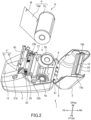
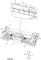
- FIG. 1A shows a case in which a printer cover 3 is in a closed state.
- Fig. 1B and 2 show cases in which the printer cover 3 is in an open state.
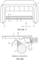
- Fig. 1B shows a state in which a paper roll "R” is set.
- Fig. 2 illustrates a paper roll "R” and shows a state of the printer 1 before the paper roll "R” is set.
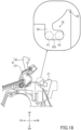
- the printer 1 can also be used with the ejection part 20 facing a horizontal direction (in a vertically held state), such as by hanging a belt hook (not shown) provided on a bottom of the printer 1, on a belt of an operator, or by attaching a shoulder strap (not shown) to the printer 1 and putting it on a shoulder of an operator.
- a pair of paper roll guides 6a are placed in the paper roll-containing chamber 9.
- the pair of paper roll guides 6a are members that rotatably support the paper roll “R” while being in contact with both side surfaces of the paper roll “R” and that guide feeding the continuous paper pulled out of the paper roll “R.”
- the paper roll guides 6a are preferably movable along a width direction of the paper roll “R” in order to vary their positions in accordance with the width of the paper roll "R.”
- a platen roller 10 (an example of a feed roller) is axially supported in a manner rotatable in forward and reverse directions, at an end of the printer cover 3.
- the platen roller 10 is a feeding unit for feeding the continuous paper "P" pulled out of the paper roll “R” and is formed in such a manner as to extend along the width direction of the continuous paper "P.”
- a gear 10b is coupled to an end of a platen shaft 10a of the platen roller 10. When the printer cover 3 is at the closed position, the gear 10b engages with a gear 22b that is disposed in the body case 2, and it is mechanically connected via the gear 22b to a roller-driving stepping motor (not shown) or the like.
- a peeling bar 12 is placed along and in the vicinity of the platen roller 10, in the printer cover 3.
- the peeling bar 12 is a peeling member for peeling labels PL from the liner PM and is fixed to both side walls of the printer cover 3 at both ends.
- the peeling bar 12 may be fixed to both ends of the platen shaft 10a.
- the cross section of the peeling bar 12 has a substantially triangle shape; however, it is not limited thereto, and it may have a spherical shape or an elliptical shape.
- the printer cover 3 is provided with a sensor 35.
- the sensor 35 is disposed in a feeding path of the continuous paper "P", along which the continuous paper "P” pulled out of the paper roll “R” reaches the platen roller 10.
- the sensor 35 detects positions of labels PL, when the printer cover 3 is in the closed state. It is preferable to control a feeding amount of the continuous paper "P” based on results detected by the sensor 35.
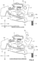
- Fig. 4 shows side views of the cover open lever 51, the peeling unit open lever 52, the platen-holding bracket 27 (an example of a locking member), and the peeling unit 4 when the printer cover is closed and when the cover open button is operated.
- Fig. 4 shows an exemplary situation in which the peeling unit 4 is at the continuous issuing position.
- the printer cover 3 which is mounted with the platen shaft 10a, is biased in the direction from the closed position to the open position.
- the printer cover 3 moves to the open position when the platen shaft 10a comes off from the groove 27b due to swinging of the platen-holding bracket 27.
- the position of the platen-holding bracket 27 at this time is an unlocking position for unlocking the printer cover 3 at the closed position.
- the shaft 41a of the peeling unit 4 is preferably inserted in the elongated hole in the printer front-rear direction, which is formed in the tubular part of the internal frame, whereby play is provided in the printer front-rear direction.
- the U-shaped groove 413 in the state of abutting and being engaged with the protrusion 26 prevents positional deviation in the printer front-rear direction of the peeling unit 4 (peeling roller cover 41) due to play of the shaft 41a inserted in the elongated hole (that is, functions as a part for positioning in the printer front-rear direction of the peeling unit 4).
- the peeling roller holder 42 is a member that holds the peeling roller 45.
- the peeling roller holder 42 when the peeling roller cover 41 is at the open position, the peeling roller holder 42 is able to swing between the contained position and the protruding position. As described later, the peeling roller holder 42 is biased in a direction from the contained position to the protruding position by a coil spring 43. Thus, immediately after the peeling roller cover 41 moves from the closed position to the open position, the peeling roller holder 42 moves in such a manner as to spring out from the contained position to the protruding position.
- This structure enables an operator to quickly switch from continuous issuing to peeling issuing.
- the peeling roller 45 When the peeling roller holder 42 is at the protruding position, the peeling roller 45 is highly protruded. This enables moving the peeling roller 45 to a distant position in setting the peeling unit 4 to the peeling issuing position.
- auxiliary rollers 46 are not necessarily provided. In the case of not using the auxiliary rollers 46, peeling issuing can be executed in the condition in which the peeling roller 45 is provided.
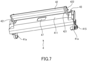
- Fig. 7 is a perspective view of the peeling unit 4 when open, as seen from a viewpoint different from that of Fig. 6 .
- the arms 421 of the peeling roller holder 42 partially abut on the surface 411 of the peeling roller cover 41.
- the surface 411 of the peeling roller cover 41 functions as a stopper for the peeling roller holder 42 that is swung by the coil spring 43.
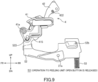
- Fig. 8 and 9 sequentially show side views of the peeling unit open lever 52 and the peeling unit 4, from states S1 to S3.
- the engaging hole 415 has, for example, a heart shape, and it allows the engaging protrusion 523 to move therein.
- the peeling unit open button 52b When the peeling unit open button 52b is pressed (operated) down, the peeling unit open lever 52 swings around the shaft 27a in a clockwise direction in Fig. 8 .
- the engaging protrusion 523 of the peeling unit open lever 52 moves upward in the engaging hole 415 and upwardly presses the peeling roller cover 41, at an upper rim of the engaging hole 415.
- the peeling roller cover 41 is thereby swung around the shaft 41a to the open position in a counterclockwise direction in Fig. 8 .
- the peeling roller holder 42 is biased in the direction for swinging from the contained position to the protruding position, by the coil spring 43 (refer to Fig. 6 ).
- the position of the shaft 42a is higher when the peeling roller cover 41 is at the open position than when the peeling roller cover 41 is at the closed position.
- space is formed in which the peeling roller holder 42 is able to swing from the contained position to the protruding position, when the peeling roller cover 41 is at the open position.
- the peeling roller holder 42 springs up by the biasing force of the coil spring 43.
- the peeling unit open lever 52 swings around the shaft 27a in the counterclockwise direction in Fig. 8 , with the restoring force of the coil spring 53.
- the peeling unit open lever 52 and the peeling roller cover 41 thereby return to the positions in the state S1.
- the peeling roller holder 42 which swings to the protruding position once, remains at the protruding position, instead of returning to the contained position.
- the peeling unit 4 is in the condition shown by the state S3 in Fig. 9 .
- the peeling unit 4 is set to the peeling issuing position while the printer cover 3 and the peeling unit 4 are engaged with each other, by swinging the printer cover 3 from the open position to the closed position in the state S3 in Fig. 9 .
- Fig. 10A is a plane view of the printer cover 3
- Fig. 10B is an enlarged view of an A-A cross section in Fig. 10A .
- the printer cover 3 has a pair of peeling unit-receiving parts 31 at front ends.
- the peeling unit-receiving part 31 is provided in the vicinity of the position at which the platen roller 10 and the peeling bar 12 are supported.
- the peeling unit-receiving part 31 is formed with a guide groove 31p that opens forward.
- the guide groove 31p is a groove that opens only to the inside along a direction from the front end to a rear end of the printer cover 3.
- the guide groove 31p receives the protrusion 422 (refer to Fig. 9 ) of the peeling unit 4 that is positioned on a front side, in the process of closing the printer cover 3.
- the roller-pressing mechanism 37 includes an abutting part 32 that is disposed in the guide groove 31p and also includes a coil spring 33 that is disposed behind the abutting part 32. In accordance with the printer cover 3 being moved to the closed position, the protrusion 422 of the peeling unit 4 is guided to the abutting part 32.
- the protrusion 422 of the peeling unit 4 enters the guide groove 31p of the peeling unit-receiving part 31 during the process of moving the printer cover 3.
- the protrusion 422 advances toward the rear of the printer cover 3 along the guide groove 31p and abuts on the abutting part 32. In this manner, the printer cover 3 engages with the peeling unit 4.
- the peeling roller 45 of the peeling unit 4 engaging with the printer cover 3 is at a position facing the platen roller 10.
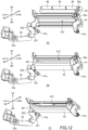
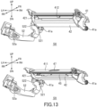
- Fig. 11 is an enlarged sectional view showing a part in the vicinity of the platen roller 10 when the printer cover 3 is completely closed and the peeling unit 4 is set to the peeling issuing position.
- restriction of swinging of the arm 421 by the first stopper 521 is released in accordance with swinging of the peeling roller cover 41.
- an outer edge of the arm 421 is formed so that restriction of swinging of the arm 421 will be released at the time the peeling roller cover 41 is closed to a predetermined angle.
- the state S8 in Fig. 13 is a state at the time the operator further closes the peeling roller cover 41 from the state S7.
- the peeling roller holder 42 in which restriction of swinging by the first stopper 521 is released, is swung by the restoring force of the coil spring 43, but it is again restricted from swinging by the second stopper 522, which is on a rear side of the first stopper 521. That is, the second stopper 522 comes into contact with the arm 421 while the peeling roller holder 42 moves from the open position to the closed position, whereby it restricts the peeling roller holder 42 from swinging between the contained position and the protruding position.
- the state S9 is a state in which the peeling roller cover 41 is at the closed position and the peeling unit 4 is at the continuous issuing position.
- the protrusion 422 of the peeling roller holder 42 at the protruding position is inserted in the guide groove 31p (refer to Fig. 10B ) of the printer cover 3 and is guided therealong, whereby the printer cover 3 and the peeling unit 4 engage with each other, as shown by the state S14.
- the printer cover 3 when the printer cover 3 reaches the closed position, the platen shaft 10a of the platen roller 10 is held by the platen-holding bracket 27, and the peeling unit 4 is set to the peeling issuing position. That is, the peeling roller 45 of the peeling unit 4 is disposed at the position facing the platen roller 10 to nip the liner PM with the platen roller 10.
- the protrusion 422 that is engaged with the printer cover 3 is pressed by the coil spring 33 (refer to Fig. 11 ), whereby an appropriate nip pressure against the platen roller 10 is generated in the peeling roller 45.
- the cover open button 51b is pressed down to open the printer cover 3, and the peeling unit open button 52b is then pressed down. This causes the peeling roller cover 41 of the peeling unit 4 to swing to the open position and also causes the peeling roller holder 42 to swing to the protruding position. Thereafter, as described with reference to Fig. 12 and 13 , the folding operation of the peeling unit 4 is performed to set the peeling unit 4 to the continuous issuing position.
- Switching from continuous issuing to peeling issuing is performed by a simple operation as follows: opening the printer cover 3; operating the peeling unit open button 52b to move the peeling roller holder 42 to the protruding position; and closing the printer cover 3. That is, switching can be performed by a simple action of these easy three steps, and operability is excellent.
- the printer cover 3 is at the closed position, the peeling roller 45 is pressed against the platen roller 10 by the roller-pressing mechanism 37 of the printer cover 3, resulting in generation of an appropriate nip pressure.
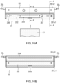
- Fig. 16A shows a front side (an example of a first side) biased by the coil spring 55, which is one of both surfaces of the thermal head 28, and Fig. 16B shows a rear side (an example of a second side) of the thermal head 28.
- the rear side of the thermal head 28 faces the platen roller 10.
- Fig. 17 shows enlarged sectional views of an A-A cross section and a B-B cross section in Fig. 16A .
- a cutout 283c is provided at a substantially center position in a longitudinal direction (lateral direction) of the surface 281a of the thermal head 28.
- the cutout 283c does not have the board 282 and exposes the surface 281a of the heat dissipation plate 281.
- the cutout 283c is configured to be in contact with a protrusion 211 (refer to Fig. 19 ) for allowing the thermal head 28 to swing.
- the board 282 that is attached to the back surface 281b of the heat dissipation plate 281 is mounted with, but not limited to, surface-mount devices (SMDs) such as a connector 285, an EEPROM 286, and a diode 287.
- SMDs surface-mount devices
- the flexible cable 57 is connected to the connector 285.
- the flexible cable 57 transmits a signal from the circuit board (not shown) of the printer 1 to the thermal head 28.
- the relatively tall surface-mount devices e.g., the connector 285, the EEPROM 286, and the diode 287 in Fig. 16A
- the relatively tall surface-mount devices which are mounted on the back surface 281b of the heat dissipation plate 281, face the front side of the printer 1.
- This configuration protects these surface-mount devices from water, etc., which may enter from the ejection part 20 on a rear side of the thermal head 28.
- a driver IC (not shown) is mounted in the vicinity of a heat generating part 284 on the rear side of the thermal head 28 facing the ejection part 20 (on a side on which the surface 281a of the heat dissipation plate 281 is provided). Due to the driver IC with low height, the driver IC and wiring are protected together with the heat generating part 284 by a protective layer or a coating layer, whereby they are unlikely to be damaged by water entering from the ejection part 20.
- the tall surface-mount devices such as the connector, are not disposed on the rear side of the thermal head 28 (on the side disposed with the heat generating part 284).
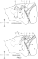
- a feed angle of a label PL relative to the heat generating part 284 can be small (in other words, it can be an angle approximately perpendicular to the heat generating part 284 in a side view) (refer to Fig. 3 ).
- good print quality is obtained due to the following reasons.
- the heat generating part 284 includes a glaze layer (partial graze) generally having a protrusion shape, and it thereby has a protrusion shape as a whole. If tall surface-mount devices are disposed on the rear side of the thermal head 28, the feeding angle of a label PL relative to the heat generating part 284 is made large in order to avoid the tall surface-mount devices. In this case, due to the heat generating part 284 having a protrusion shape and to stiffness (resilience) of a label PL, the label PL tends to rise from the heat generating part 284 at the position thereof, and it is difficult to apply an appropriate printing pressure to the label PL between the heat generating part 284 and the platen roller 10.
- a glaze layer partial graze
- the heat generating part 284 pinches a label PL with the platen roller 10 by applying an appropriate printing pressure, in the vicinity of a top of the heat generating part 284.
- good print quality is obtained.
- a pair of shafts 28a that extend outward are coupled to both end surfaces of the heat dissipation plate 281. As described later, the pair of shafts 28a are provided in order to mount the thermal head 28 to the internal frame of the printer 1. As shown in Fig. 16A and 16B , the shaft 28a has a large-diameter part joined to the heat dissipation plate 281 and has a small-diameter part extending outward from the large-diameter part, and it thereby has a high strength. The small-diameter part of the shaft 28a is inserted in a shaft-receiving groove 25, which will be described later.
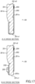
- Fig. 18 is a partial sectional view of the printer 1 in a plane perpendicular to the right-left direction, in the state in which the peeling unit open button 52b is continuously pressed down to make the peeling roller cover 41 be at the open position and to make the peeling roller holder 42 be at the protruding position.
- Fig. 17 does not show the thermal head 28 and the coil spring 55, in order to make the shaft-receiving groove 25, into which the shaft 28a of the thermal head 28 is inserted, clearly visible.
- the internal frame of the printer 1 is formed with the shaft-receiving groove 25 having a substantially L-shape.
- Fig. 18 shows only a shaft-receiving groove 25 that receives one of the pair of shafts 28a of the thermal head 28, another shaft-receiving groove 25 that receives the other shaft 28a is also formed in the same manner.
- the shaft-receiving groove 25 has a first groove 251 and a second groove 252.
- each of positions P1 and P2 shows a position where the shaft 28a can be in the shaft-receiving groove 25, in a virtual manner.
- the state in which the shaft 28a is at the position P1 may be referred to as a state in which the thermal head 28 is at the position P1; the state in which the shaft 28a is at the position P2 may be referred to as a state in which the thermal head 28 is at the position P2.
- the first groove 251 extends in a direction in which the thermal head 28 moves to and away from the position P1 (an example of a first position of a print head).
- the second groove 252 extends from the position P1 to the position P2 (an example of a second position of a print head) in a direction in which the coil spring 55 in front of the thermal head 28 biases the thermal head 28 (that is, in a rear direction; an example of a first direction).
- the shaft-receiving groove 25 is an L-shaped groove composed of the first groove 251 and the second groove 252, and therefore, the position of the thermal head 28 can be switched between two positions P1, P2 by this relatively simple shape.
- the position P2 is a position at which the thermal head 28 cannot be removed by moving it upward
- the position P1 is a position at which the thermal head 28 can be removed by moving it upward.
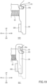
- Fig. 19 illustrates a method of replacing the thermal head 28 and shows partial side views of a replacement-target thermal head 28 in states S20 and S21.
- the replacement-target thermal head 28, which is mounted to the printer 1, is disposed at the position P2 of the shaft-receiving groove 25, as shown by the state S20.
- the whole thermal head 28 is biased to the platen roller 10 (not shown in Fig. 19 ) (that is, in the rear direction) by the biasing force of the coil spring 55, and the shaft 28a of the thermal head 28 is thereby stably positioned at the position P2.
- the replacement-target thermal head 28 In order to remove the replacement-target thermal head 28, it is moved from the position P2 to the position P1 in a direction opposite to a first direction, against the biasing force of the coil spring 55, as shown by the state S21.
- the first direction is a direction in which the coil spring 55 biases the thermal head 28, and the direction opposite to the first direction is a front direction.
- the replacement-target thermal head 28 is moved upward (an example of a second direction) from the position P1, and the shaft 28a of the replacement-target thermal head 28 is removed from the shaft-receiving groove 25, whereby the replacement-target thermal head 28 is removed.
- the flexible cable 57 is connected to the connector 285 of the replacement-target thermal head 28 (refer to Fig. 21B ).
- the flexible cable 57 is disconnected from the connector 285 of the replacement-target thermal head 28.
- a new thermal head 28 may be mounted to the printer 1 in a procedure reverse to the procedure of taking out the thermal head 28.
- the disconnected flexible cable 57 is first connected to the connector 285 of a new thermal head 28 (refer to Fig. 16A ).
- the new thermal head 28 is then inserted into the position P1 and is moved from the position P1 to the position P2 by the biasing force of the coil spring 55.
- the new thermal head 28 is moved downward (an example of an opposite direction to a second direction), and the shaft 28a of the new thermal head 28 is inserted into the shaft-receiving groove 25 from the first groove 251 (refer to Fig. 18 ).
- thermal head 28 is replaced as described above.
- the thermal head 28 is not disposed with the surface-mount devices, such as the connector, on the rear side (on the side disposed with the heat generating part 284), as shown in Fig. 16B , and it is thereby easy to replace. Also, in consideration of the coil spring 55 biasing the thermal head 28 rearward, if the thermal head 28 did not have a flat rear side, it would interfere with the internal frame on a rear side (e.g., a wall surface 21; refer to Fig. 20 ) and would be difficult to smoothly insert into the shaft-receiving groove 25. In contrast, due to the thermal head 28 having a flat rear side, the new thermal head 28 can be smoothly inserted into the shaft-receiving groove 25, although biased by the coil spring 55.
- the peeling unit 4 at the closed position covers at least a part of the thermal head 28, whereas the peeling unit 4 at the open position does not cover the thermal head 28, as shown in Fig. 2 .
- mounting and removing of the thermal head 28 are performed when the peeling unit 4 is at the open position.
- the peeling unit 4 When the peeling unit 4 is at the closed position, none of other member is interposed between the peeling unit 4 and the thermal head 28, and the peeling unit 4 directly covers at least a part of the thermal head 28.
- the printer 1 of this embodiment at least a part of the rear side of the thermal head 28 is exposed to the paper roll-containing chamber 9, as shown in Fig. 2 .
- working space for taking out the thermal head 28 is ensured by temporarily removing the paper roll "R," which enables more easily taking out the thermal head 28.
- an operator in sliding the shaft 28a of the thermal head 28 from the position P2 to the position P1, an operator needs to apply an operating force to the thermal head 28 from a rear side to a front side, but the operating force is easily applied due to the space behind the thermal head 28.
- the space behind the thermal head 28 helps an operator in putting a hand therein and pulling up.
- the peeling unit 4 is set to the state shown in Fig. 18 . Then, the shaft 28a of the thermal head 28 is inserted into the position P1 from the first groove 251 of the shaft-receiving groove 25 while the end of the coil spring 55 (rear end of the coil spring 55) is pressed forward (in the direction against the biasing force of the coil spring 55) by the back surface 281b (surface facing forward of the printer 1) of the thermal head 28. The thermal head 28 is then moved to the position P2 by the biasing force of the coil spring 55.
- the thermal head 28 can be easily replaced without using tools.
- the shaft-receiving groove may have another shape, instead of the L-shape.
- the shaft-receiving groove may have, for example, a groove extending obliquely forward or extending obliquely rearward from the position P1, as long as the thermal head 28 can be attached and removed from the position P1.
- the shaft-receiving groove may have a U-shaped groove path between the positions P1 and P2 in such a manner that the position P2 is provided at a position that the path reaches after starting from the position P1 in Fig. 18 , extending forward, extending slightly downward, and then extending rearward, although this structure causes mounting and removing the thermal head 28 to be a little difficult. In this case, an operator can remove the shaft 28a of the thermal head 28 by moving it from the position P2 to the position P1 along the U-shaped groove.
- Fig. 20 is a perspective view of a part of the internal frame along with components attached to the internal frame, a part of which is enlarged. Fig. 20 does not show the thermal head 28.
- the internal frame has a wall surface 21 that is configured to face the rear surface of the thermal head 28, behind an area to be disposed with the thermal head 28 (on a paper roll-containing chamber 9 side).
- the wall surface 21 is formed with a protrusion 211.
- the protrusion 211 abuts on the rear surface of the thermal head 28 that is mounted.
- the abutting surface of the protrusion 211 is preferably curved so as to be convex toward the rear surface of the thermal head 28.
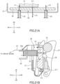
- Fig. 21A and 21B both illustrate forces that act on the thermal head 28 in the printer 1 of this embodiment;
- Fig. 21A shows a cross section in a plane perpendicular to the upper-lower direction, and
- Fig. 21B shows a cross section in a plane perpendicular to the right-left direction.
- Fig. 21A and 21B have scales different from each other.
- the protrusion 211 is provided at a position at which it abuts on a substantially center part in the right-left direction of the thermal head 28 that is mounted.
- the protrusion 211 is provided at a position at which it abuts on a substantially center position in the right-left direction between the pair of coil springs 55, of the rear side of the thermal head 28.
- the cutout 283c (refer to Fig. 16B ) is provided at the approximate center in the right-left direction of the thermal head 28, as described above, and the protrusion 211 abuts on the thermal head 28 at the cutout 283c.
- the cutout 283c is not covered with the board 282 and exposes the heat dissipation plate 281 of the thermal head 28, whereby the thermal head 28 is more stably supported.
- the cutout 283c is not necessarily provided.
- the protrusion 211 may support the thermal head 28 at an area of the board 282, without the cutout 283c provided.
- the rear surface of the thermal head 28 is preferably provided with a recess having a shape corresponding to the protrusion 211, at the position for abutting on the protrusion 211. This causes the thermal head 28 to hardly deviate from the position for abutting on the protrusion 211 and to be more stably supported.
- a recess may be provided in the wall surface 21 of the internal frame, whereas the rear surface of the thermal head 28 may be provided with a protrusion having a shape corresponding to the recess of the wall surface 21.
- the thermal head 28 is also able to swing, but it is stably supported.
- the shape of the protrusion 211 shown in Fig. 20 is merely an example, and it can be another shape that swingably supports the thermal head 28.
- the outer shape of the protrusion 211 may be a part of a spherical surface, instead of the shape shown in Fig. 20 .
- a reaction force F3 acts from the protrusion 211 abutting on the rear side of the thermal head 28.
- the protrusion 211 is at the approximate center position in a top view of the printer 1, and thus, the thermal head 28 is able to swing around a fulcrum at the protrusion 211, in a clockwise direction and a counterclockwise direction in Fig. 21A .
- the thermal head 28 is able to swing around a fulcrum at the protrusion 211, in a clockwise direction and a counterclockwise direction in Fig. 21B .
- the points of applying the biasing forces of the coil springs 55 to the thermal head 28 are between the position at which the thermal head 28 receives the reaction force from the platen roller 10 and the position at which the protrusion 211 supports the rear side of the thermal head 28.
- the biasing forces of the coil springs 55 are received at an upper part and a lower part, whereby the thermal head 28 is supported with good balance.
- the surface on which the protrusion 211 abuts (that is, the surface on which the heat dissipation plate 281 is exposed by the cutout 283c), and the surface corresponding to the heat generating part 284, are preferably in the same reference plane on the rear side of the thermal head 28. This enables pressing the heating elements of the thermal head 28 against the platen roller 10 at an appropriate angle.
- the thermal head 28 is able to swing around a fulcrum at the protrusion 211 in a clockwise swinging direction and a counterclockwise swinging direction in a side view of the printer 1.
- the thermal head 28 is also able to swing around a fulcrum at the protrusion 211 in a clockwise swinging direction and a counterclockwise swinging direction in a plane view of the printer 1.
- the thermal head 28 uniformly applies pressure to the platen roller 10 in printing. The reason of this is as follows.
- the thermal head In a printer having an existing thermal head, the thermal head is fixed, for example, at two points, by using screws, shafts, brackets, or the like, so as to be mounted to an internal frame or a housing of the printer. In such a case, due to deviation of the mounted position, the pressure of the thermal head abutting on a platen roller may not be uniform in an axial direction of the platen roller, which may cause degradation in print quality.
- the thermal head 28 is able to swing around a fulcrum at the protrusion 211 in a side view and in a plane view of the printer 1. With this structure, the thermal head 28 can follow and maintain uniform pressure on the platen roller 10, for example, even when there is a mounting error of the platen roller 10, circular runout of the platen roller 10 is large in rotating, or a rugged surface label is temporarily attached on a liner.
- the thermal head 28 is movable between the positions P1 and P2 (refer to Fig. 18 ) in the direction of being biased by the coil spring 55, and thus, the thermal head 28 is not prevented from swinging around a fulcrum at the protrusion 211.
- a fulcrum shaft is provided at a lower part of the thermal head, and this shaft is fixed to a printer body to enable the thermal head to swing in a side view.
- this thermal head cannot be replaced without using tools.
- the printer 1 is superior to existing ones in that the thermal head 28 can be replaced without using tools while enabling to swing in a side view and in a plane view of the printer 1.
- protrusions 211 may be provided at two positions separated in the right-left direction on the wall surface 21 shown in Fig. 20 . Also in this case, the thermal head 28 is able to swing around fulcrums at the protrusions 211 in a side view of the printer 1. Even in the case in which the thermal head 28 is able to swing only in a side view of the printer 1, degradation in print quality is prevented.
- protrusions 211 may be provided at two positions separated in the upper-lower direction on the wall surface 21 shown in Fig. 20 . Also in this case, the thermal head 28 is able to swing around fulcrums at the protrusions 211 in a plane view of the printer 1. Even in the case in which the thermal head 28 is able to swing only in a plane view of the printer 1, degradation in print quality is prevented.
- the flexible cable 57 is detachably connected to the thermal head 28.
- the flexible cable 57 is connected from the connector 285 of the thermal head 28 that is mounted to the printer 1, to the circuit board (not shown) at a front part of the printer 1, as shown in Fig. 21B .
- the flexible cable 57 is fixed at a fixing position 24a on an upper surface of a bracket 24 in front of the thermal head 28, for example, by screwing or adhesive.
- a cable-containing chamber 59 for containing the flexible cable 57 is formed between the thermal head 28 and the circuit board.
- the cable-containing chamber 59 is configured to contain the relatively long flexible cable 57 between the connector of the thermal head 28 and the fixing position 24a.
- the cable-containing chamber 59 is not necessarily formed. Even in this case, although the cable length from the connector 285 of the thermal head 28 to the fixing position 24a is reduced, it is possible to remove the flexible cable 57 from the connector 285 and to replace the thermal head 28.
- the cable-containing chamber 59 is formed in space between the platen-holding bracket 27 and the thermal head 28.
- the space that is formed by the platen-holding bracket 27 having a U-shape in a plane view is efficiently used.
- the cable-containing chamber 59 may not be formed as the space between the platen-holding bracket 27 and the thermal head 28.
- the flexible cable 57 extending from the connector of the thermal head 28 may be passed under the platen-holding bracket 27, and a containing chamber may be provided on a front side of the platen-holding bracket 27.
- the surface-mount devices are not mounted on the rear surface of the thermal head 28 and are thereby protected from water, etc., which may enter from the ejection part 20.
- space for allowing mounting and removing the thermal head 28 is formed when the peeling unit 4 is at the open position not covering the thermal head 28, which improves the workability in replacing the thermal head 28.
- the thermal head 28 is biased rearward (in a direction to the platen roller 10) and is movable along this direction between the first position for allowing mounting and removing the thermal head 28 and the second position for restricting mounting and removing of the thermal head 28.
- the thermal head 28 can be removed only by moving it from the second position to the first position, and tools and the like are not necessary.
- the thermal head 28 is able to swing around a fulcrum at the protrusion 211 in a clockwise swinging direction and a counterclockwise swinging direction in a side view of the printer 1, and the thermal head 28 is also able to swing around a fulcrum at the protrusion 211 in a clockwise swinging direction and a counterclockwise swinging direction in a plane view of the printer 1.
- the thermal head 28 uniformly applies pressure to the platen roller 10 in printing, and it is possible to prevent degradation in print quality due to the method of mounting the thermal head.
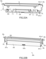
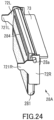
- thermal head 28A according to another embodiment will be described with reference to Fig. 22A to 25 .
- Fig. 22A is a perspective front view of the thermal head 28A
- Fig. 22B is a perspective rear view of the thermal head 28A
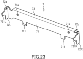
- Fig. 23 is a perspective view of a plate member included in the thermal head 28A
- Fig. 24 is a perspective view of the thermal head 28A, as seen from a viewpoint different from those of Fig. 22A and 22B .
- the plate member 7 which is a member formed of a metal material such as stainless steel, is fastened to the heat dissipation plate 281 with screws. As shown in Fig. 23 , the plate member 7 has a base 71, projecting pieces 72L and 72R, and a projecting plate 73.
- the projecting pieces 72L and 72R project from both ends of the base 71 in a direction perpendicular to a main surface of the base 71 (that is, in a direction perpendicular to the surface 281a when they are attached to the heat dissipation plate 281).
- the projecting pieces 72L and 72R project on a side mounted with the heat generating part 284, as shown in Fig. 24 .
- the projecting pieces 72L and 72R have edge parts 721L and 721R at ends.
- the projecting piece 72L is formed with a hole 72a, whereas the projecting piece 72R is formed with a U-shaped groove 72b.
- the projecting piece 72R is formed with a U-shaped groove 72b.
- one of the pair of shafts 28a is inserted in the hole 72a, and the other shaft 28a is inserted in the U-shaped groove 72b.
- One of the edge parts 721L and 721R is formed with a hole, and the other is formed with a U-shaped groove. This facilitates attaching the plate member 7 to the heat dissipation plate 281.
- the projecting plate 73 projects on a side mounted with the relatively tall surface-mount devices (e.g., the connector 285, the EEPROM 286, and the diode 287), as shown in Fig. 22A .
- the relatively tall surface-mount devices e.g., the connector 285, the EEPROM 286, and the diode 287
- the projecting plate 73 is provided between the projecting pieces 72L and 72R over the longitudinal direction of the base 71 and projects from the base 71 in a direction opposite to the projecting pieces 72L and 72R.
- the base 71 is formed with two holes 71a for allowing screws to pass in mounting the plate member 7 to the heat dissipation plate 281.
- the base 71 has two projections 711. As shown in Fig. 22A , the projections 711 are disposed so as to not interfere with the surface-mount devices when the plate member 7 is attached to the heat dissipation plate 281.
- Fig. 25 is a side view showing a positional relationship between the thermal head 28A and the platen-holding bracket 27.
- the platen shaft 10a of the platen roller 10, which is attached to the printer cover 3 is fitted in the groove 27b of the platen-holding bracket 27, whereby the printer cover 3 is held.
- the platen roller 10 may deviate downward from a designed position at which the platen roller 10 and the thermal head 28 abut on each other. This causes variations in density of printing.
- the thermal head 28 is fitted to the shaft-receiving groove 25 (refer to Fig. 18 ), which is provided in the internal frame.
- the one end of the shaft 27a of the platen-holding bracket 27 is inserted in the boss 52a of the peeling unit open lever 52, whereas the other end of the shaft 27a is inserted in the boss provided to the internal frame (refer to Fig. 5 ).
- the position at which the platen roller 10 and the thermal head 28 abut on each other is susceptible to accumulated errors in assembling components and tends to deviate from the designed position.
- thermal head 28A The drawback of the thermal head 28 noted above is overcome by the thermal head 28A.
- the plate member 7 is integrally coupled to the heat dissipation plate 281 mounted with the heat generating part 284, whereby a relative positional relationship between the platen roller 10 and the heat generating part 284 is unlikely to be affected even when the platen shaft 10a presses down the edge parts 721L and 721R.
- the projecting plate 73 of the plate member 7 projects toward the front side of the printer 1.
- an upper part of the cable-containing chamber 59, which is formed in front of the thermal head 28A is covered with the projecting plate 73.
- This structure prevents dust from entering the printer 1 from the outside, resulting in preventing dust from adhering to upper surface portions of the surface-mount devices disposed on the front side of the thermal head 28A. That is, the projecting plate 73 functions as a hood.
- replacement of the paper roll "R" is performed while the printer cover 3 is maintained at the open position, and dust tends to enter the printer 1.
- the structures and the mounting and removing methods of the thermal heads 28 and 28A are not technically related to the structure of the peeling unit 4 and the method of switching the issue modes, and therefore, they may be employed in a printer without the peeling unit 4.
- the structure of the peeling unit 4 and the method of switching the issue modes may be employed in a printer that uses a structure and an mounting and removing method of a thermal head different from those of the thermal heads 28 and 28A.
- a case in which some parts (e.g., shafts and ends of springs) of components inside the printer 1 are coupled to the internal frame is described here; but the structure is not limited thereto, and these parts may be coupled to the body case 2.
- the print medium is not limited thereto.
- a continuous label having an adhesive surface on one side label without a liner
- a continuous sheet without an adhesive surface continuous sheet
- a material other than papers such as a film, which is printable by a thermal head
- a feeding path may be coated with a non-adhesive material, and a non-adhesive roller containing silicone or the like may be provided as a platen roller.
- the present invention is related to Japanese Patent Application No. JP 2020- 191 562 A filed with the Japan Patent Office on November 18, 2020 .
Landscapes
- Electronic Switches (AREA)
- Accessory Devices And Overall Control Thereof (AREA)
- Printers Characterized By Their Purpose (AREA)
- Common Mechanisms (AREA)
Claims (5)
- Drucker (1), umfassend:eine Zuführwalze (10), die so konfiguriert ist, dass sie ein Druckmedium (P) zuführt;einen Druckkopf (28, 28A), der so konfiguriert ist, dass er das Druckmedium (P) mit der Zuführwalze (10) einklemmt und auf das Druckmedium (P) druckt; undein Vorspannelement (55), das so konfiguriert ist, dass es den Druckkopf (28, 28A) in einer ersten Richtung zur Zuführwalze (10) hin vorspannt,wobei der Druckkopf (28, 28A) in der ersten Richtung zwischen einer ersten Position (P1) und einer zweiten Position (P2) beweglich ist, wobei die erste Position eine Position ist, an der der Druckkopf (28, 28A) entfernbar ist, wenn er in eine zweite Richtung bewegt wird, wobei die zweite Position eine Position ist, an der der Druckkopf (28, 28A) nicht entfernbar ist, wenn er in die zweite Richtung bewegt wird, wobeider Druckkopf (28, 28A) umfasst: eine Basis (281), auf der Heizelemente montiert sind; und ein Paar Wellen (28a), die sich von beiden Enden der Basis (281) nach außen erstrecken,der Drucker (1) ferner ein Paar von Nuten (25) umfasst, die das Paar von Wellen (28a) aufnehmen, wobei das Paar von Nuten (25) eine erste Nut (251) und eine zweite Nut (252) umfasst, wobei sich die erste Nut von der ersten Position in die zweite Richtung erstreckt, wobei sich die zweite Nut von der ersten Position zu der zweiten Position in die erste Richtung erstreckt,dadurch gekennzeichnet, dassdas Druckmedium (P) eine Trägerfolie (PM) und Etiketten (PL) umfasst, die lösbar auf der Trägerfolie befestigt sind,es möglich ist, im Drucker (1) zwischen Abziehausgabe und fortlaufender Ausgabe umzuschalten, wobei bei der Abziehausgabe die Etiketten ausgebbar sind, nachdem sie von der Trägerfolie des Druckmediums abgezogen wurden, und bei der kontinuierlichen Ausgabe die Etiketten ausgebbar sind, ohne dass sie von der Trägerfolie abgezogen werden,der Drucker (1) ferner eine Abzieheinheit (4) umfasst, die so konfiguriert ist, dass sie eine Abziehwalze (45) hält, die bei der Abziehausgabe der Zuführwalze (10) zugewandt ist, wobei die Abzieheinheit (4) zwischen einer geschlossenen Position und einer offenen Position beweglich ist, wobei die geschlossene Position, in der die Abzieheinheit (4) den Druckkopf (28, 28A) zumindest teilweise abdeckt, und die offene Position eine Position ist, in der die Abzieheinheit (4) den Druckkopf (28, 28A) nicht abdeckt, undwenn sich die Abzieheinheit (4) in der offenen Position befindet und das Paar von Wellen (28a) sich in der ersten Position befindet, ein Raum gebildet wird, der das Anbringen und Entfernen des Druckkopfs (28, 28A) ermöglicht.
- Drucker (1) gemäß Anspruch 1, der ferner eine Rollenkörper-Aufnahmekammer (9) umfasst, die so konfiguriert ist, dass sie eine Rolle (R) aufnimmt, auf die das Druckmedium (P) aufgewickelt ist, wobeider Druckkopf (28, 28A) umfasst: eine erste Seite, die durch das Vorspannelement (55) vorgespannt ist, und eine zweite Seite, die der ersten Seite gegenüberliegt, wobei die zweite Seite der Zuführwalze (10) zugewandt ist, undmindestens ein Teil der zweiten Seite des Druckkopfs (28, 28A) zu der Rollenkörper-Aufnahmekammer (9) freiliegt.
- Drucker (1) gemäß Anspruch 1 oder 2, ferner umfassend:eine Leiterplatte;ein flexibles Kabel (57), das so konfiguriert ist, dass es den Druckkopf (28, 28A) und die Leiterplatte verbindet; undeine Kabelaufnahmekammer (59) zur Aufnahme des flexiblen Kabels (57), wobei die Kabelaufnahmekammer (59) zwischen dem Druckkopf (28, 28A) und der Leiterplatte ausgebildet ist.
- Drucker (1) gemäß Anspruch 3, ferner umfassend:eine Druckerabdeckung (3), die zwischen einer offenen Position zum Freilegen eines Inneren des Druckers (1) und einer geschlossenen Position zum Abdecken des Inneren des Druckers (1) schwenkbar ist, wobei die Zuführwalze (10) an der Druckerabdeckung (3) befestigt ist, undein Verriegelungselement (27) zwischen einer Verriegelungsposition zum Verriegeln der Druckerabdeckung (3) in der geschlossenen Position und einer Entriegelungsposition zum Entriegeln der Druckerabdeckung (3) in der geschlossenen Position schwenkbar ist,wobei die Kabelaufnahmekammer in einem Raum zwischen dem Verriegelungselement (27) und dem Druckkopf (28, 28A) ausgebildet ist.
- Verfahren zum Austauschen eines Druckkopfs (28, 28A) eines Druckers (1) gemäß einem der Ansprüche 1 bis 4, wobei das Verfahren umfasst:Bewegen eines Ersatzziel-Druckkopfs (28, 28A) in einer zur ersten Richtung entgegengesetzten Richtung von einer zweiten Position zu einer ersten Position gegen eine Vorspannkraft des Vorspannelements (55);Bewegen des Ersatzziel-Druckkopfs (28, 28A) in einer zweiten Richtung von der ersten Position, um den Ersatzziel-Druckkopf (28, 28A) zu entfernen; undEinsetzen eines neuen Druckkopfs (28, 28A) in die erste Position, um den neuen Drucckopf (28, 28A) von der ersten Position in die zweite Position mit der Vorspannkraft des Vorspannelements (55) zu bewegen,wenn die Abzieheinheit (4) in die offene Position bewegt wird und das Paar von Wellen (28a) in der ersten Position ist, Bilden eines Raums, der das Anbringen und Entfernen des Drucckopfs (28, 28A) ermöglicht.
Applications Claiming Priority (2)
| Application Number | Priority Date | Filing Date | Title |
|---|---|---|---|
| JP2020191562A JP7620414B2 (ja) | 2020-11-18 | 2020-11-18 | プリンタ、プリンタの印字ヘッドの交換方法 |
| PCT/JP2021/041360 WO2022107662A1 (ja) | 2020-11-18 | 2021-11-10 | プリンタ、プリンタの印字ヘッドの交換方法 |
Publications (3)
| Publication Number | Publication Date |
|---|---|
| EP4249267A1 EP4249267A1 (de) | 2023-09-27 |
| EP4249267A4 EP4249267A4 (de) | 2024-03-13 |
| EP4249267B1 true EP4249267B1 (de) | 2025-01-29 |
Family
ID=81708897
Family Applications (1)
| Application Number | Title | Priority Date | Filing Date |
|---|---|---|---|
| EP21894536.8A Active EP4249267B1 (de) | 2020-11-18 | 2021-11-10 | Drucker und verfahren zum ersetzen des druckkopfes eines druckers |
Country Status (5)
| Country | Link |
|---|---|
| US (1) | US12370807B2 (de) |
| EP (1) | EP4249267B1 (de) |
| JP (1) | JP7620414B2 (de) |
| CN (1) | CN116490372B (de) |
| WO (1) | WO2022107662A1 (de) |
Families Citing this family (4)
| Publication number | Priority date | Publication date | Assignee | Title |
|---|---|---|---|---|
| JP2023169030A (ja) * | 2022-05-16 | 2023-11-29 | 株式会社三洋物産 | 遊技機 |
| JP2023169029A (ja) * | 2022-05-16 | 2023-11-29 | 株式会社三洋物産 | 遊技機 |
| EP4624179A4 (de) * | 2022-11-22 | 2026-03-04 | Sato Kk | Drucker, programm und verfahren zur steuerung des druckers |
| JP2026012994A (ja) * | 2024-07-16 | 2026-01-28 | Fclコンポーネント株式会社 | 印刷装置 |
Family Cites Families (10)
| Publication number | Priority date | Publication date | Assignee | Title |
|---|---|---|---|---|
| US5625400A (en) | 1994-03-11 | 1997-04-29 | Aoi Electronics Co., Ltd. | Positioning device for a document processing device |
| JP2915277B2 (ja) * | 1994-03-11 | 1999-07-05 | アオイ電子株式会社 | 印字装置 |
| JP3627347B2 (ja) * | 1996-02-13 | 2005-03-09 | セイコーエプソン株式会社 | サーマルヘッドの押圧機構及びそれを用いたプリンタ |
| JP3614314B2 (ja) * | 1999-03-25 | 2005-01-26 | セイコーエプソン株式会社 | プリンタ |
| JP4412531B2 (ja) | 2003-09-18 | 2010-02-10 | セイコーインスツル株式会社 | サーマルプリンタ |
| US7399130B2 (en) | 2004-03-03 | 2008-07-15 | Zih Corporation | Printer with quick release print head and platen to promote installation and removal of same |
| JP2015214048A (ja) | 2014-05-08 | 2015-12-03 | サトーホールディングス株式会社 | プリンタ |
| JP6795280B2 (ja) | 2014-05-26 | 2020-12-02 | サトーホールディングス株式会社 | プリンタ |
| JP6722796B2 (ja) * | 2019-03-28 | 2020-07-15 | サトーホールディングス株式会社 | プリンタ |
| JP2020191562A (ja) | 2019-05-22 | 2020-11-26 | 富士ゼロックス株式会社 | 情報処理装置及びプログラム |
-
2020
- 2020-11-18 JP JP2020191562A patent/JP7620414B2/ja active Active
-
2021
- 2021-11-10 EP EP21894536.8A patent/EP4249267B1/de active Active
- 2021-11-10 US US18/037,061 patent/US12370807B2/en active Active
- 2021-11-10 WO PCT/JP2021/041360 patent/WO2022107662A1/ja not_active Ceased
- 2021-11-10 CN CN202180076398.5A patent/CN116490372B/zh active Active
Also Published As
| Publication number | Publication date |
|---|---|
| EP4249267A1 (de) | 2023-09-27 |
| JP7620414B2 (ja) | 2025-01-23 |
| US20240025185A1 (en) | 2024-01-25 |
| EP4249267A4 (de) | 2024-03-13 |
| WO2022107662A1 (ja) | 2022-05-27 |
| CN116490372A (zh) | 2023-07-25 |
| CN116490372B (zh) | 2025-11-11 |
| JP2022080471A (ja) | 2022-05-30 |
| US12370807B2 (en) | 2025-07-29 |
Similar Documents
| Publication | Publication Date | Title |
|---|---|---|
| EP4249267B1 (de) | Drucker und verfahren zum ersetzen des druckkopfes eines druckers | |
| EP4249268B1 (de) | Druckmaschine | |
| EP4249274B1 (de) | Druckmaschine | |
| EP4249273B1 (de) | Druckmaschine | |
| EP4249269B1 (de) | Thermokopf und drucker | |
| CN116547154B (en) | Printer with a printer body | |
| JP7585002B2 (ja) | プリンタ |
Legal Events
| Date | Code | Title | Description |
|---|---|---|---|
| STAA | Information on the status of an ep patent application or granted ep patent |
Free format text: STATUS: THE INTERNATIONAL PUBLICATION HAS BEEN MADE |
|
| PUAI | Public reference made under article 153(3) epc to a published international application that has entered the european phase |
Free format text: ORIGINAL CODE: 0009012 |
|
| STAA | Information on the status of an ep patent application or granted ep patent |
Free format text: STATUS: REQUEST FOR EXAMINATION WAS MADE |
|
| 17P | Request for examination filed |
Effective date: 20230509 |
|
| AK | Designated contracting states |
Kind code of ref document: A1 Designated state(s): AL AT BE BG CH CY CZ DE DK EE ES FI FR GB GR HR HU IE IS IT LI LT LU LV MC MK MT NL NO PL PT RO RS SE SI SK SM TR |
|
| REG | Reference to a national code |
Ref country code: DE Ref legal event code: R079 Free format text: PREVIOUS MAIN CLASS: B41J0002320000 Ipc: B41J0025340000 Ref country code: DE Ref legal event code: R079 Ref document number: 602021025694 Country of ref document: DE Free format text: PREVIOUS MAIN CLASS: B41J0002320000 Ipc: B41J0025340000 |
|
| DAV | Request for validation of the european patent (deleted) | ||
| DAX | Request for extension of the european patent (deleted) | ||
| A4 | Supplementary search report drawn up and despatched |
Effective date: 20240209 |
|
| RIC1 | Information provided on ipc code assigned before grant |
Ipc: B41J 3/407 20060101ALN20240205BHEP Ipc: B41J 2/32 20060101ALI20240205BHEP Ipc: B41J 25/312 20060101ALI20240205BHEP Ipc: B41J 25/34 20060101AFI20240205BHEP |
|
| GRAP | Despatch of communication of intention to grant a patent |
Free format text: ORIGINAL CODE: EPIDOSNIGR1 |
|
| STAA | Information on the status of an ep patent application or granted ep patent |
Free format text: STATUS: GRANT OF PATENT IS INTENDED |
|
| RIC1 | Information provided on ipc code assigned before grant |
Ipc: B41J 3/407 20060101ALN20240807BHEP Ipc: B41J 2/32 20060101ALI20240807BHEP Ipc: B41J 25/312 20060101ALI20240807BHEP Ipc: B41J 25/34 20060101AFI20240807BHEP |
|
| INTG | Intention to grant announced |
Effective date: 20240819 |
|
| P01 | Opt-out of the competence of the unified patent court (upc) registered |
Free format text: CASE NUMBER: APP_55536/2024 Effective date: 20241009 |
|
| GRAS | Grant fee paid |
Free format text: ORIGINAL CODE: EPIDOSNIGR3 |
|
| GRAA | (expected) grant |
Free format text: ORIGINAL CODE: 0009210 |
|
| STAA | Information on the status of an ep patent application or granted ep patent |
Free format text: STATUS: THE PATENT HAS BEEN GRANTED |
|
| AK | Designated contracting states |
Kind code of ref document: B1 Designated state(s): AL AT BE BG CH CY CZ DE DK EE ES FI FR GB GR HR HU IE IS IT LI LT LU LV MC MK MT NL NO PL PT RO RS SE SI SK SM TR |
|
| REG | Reference to a national code |
Ref country code: GB Ref legal event code: FG4D |
|
| REG | Reference to a national code |
Ref country code: CH Ref legal event code: EP |
|
| REG | Reference to a national code |
Ref country code: DE Ref legal event code: R096 Ref document number: 602021025694 Country of ref document: DE |
|
| REG | Reference to a national code |
Ref country code: IE Ref legal event code: FG4D |
|
| REG | Reference to a national code |
Ref country code: NL Ref legal event code: MP Effective date: 20250129 |
|
| PG25 | Lapsed in a contracting state [announced via postgrant information from national office to epo] |
Ref country code: NL Free format text: LAPSE BECAUSE OF FAILURE TO SUBMIT A TRANSLATION OF THE DESCRIPTION OR TO PAY THE FEE WITHIN THE PRESCRIBED TIME-LIMIT Effective date: 20250129 |
|
| PG25 | Lapsed in a contracting state [announced via postgrant information from national office to epo] |
Ref country code: RS Free format text: LAPSE BECAUSE OF FAILURE TO SUBMIT A TRANSLATION OF THE DESCRIPTION OR TO PAY THE FEE WITHIN THE PRESCRIBED TIME-LIMIT Effective date: 20250429 |
|
| PG25 | Lapsed in a contracting state [announced via postgrant information from national office to epo] |
Ref country code: FI Free format text: LAPSE BECAUSE OF FAILURE TO SUBMIT A TRANSLATION OF THE DESCRIPTION OR TO PAY THE FEE WITHIN THE PRESCRIBED TIME-LIMIT Effective date: 20250129 |
|
| PG25 | Lapsed in a contracting state [announced via postgrant information from national office to epo] |
Ref country code: PL Free format text: LAPSE BECAUSE OF FAILURE TO SUBMIT A TRANSLATION OF THE DESCRIPTION OR TO PAY THE FEE WITHIN THE PRESCRIBED TIME-LIMIT Effective date: 20250129 |
|
| PG25 | Lapsed in a contracting state [announced via postgrant information from national office to epo] |
Ref country code: ES Free format text: LAPSE BECAUSE OF FAILURE TO SUBMIT A TRANSLATION OF THE DESCRIPTION OR TO PAY THE FEE WITHIN THE PRESCRIBED TIME-LIMIT Effective date: 20250129 |
|
| REG | Reference to a national code |
Ref country code: LT Ref legal event code: MG9D |
|
| PG25 | Lapsed in a contracting state [announced via postgrant information from national office to epo] |
Ref country code: IS Free format text: LAPSE BECAUSE OF FAILURE TO SUBMIT A TRANSLATION OF THE DESCRIPTION OR TO PAY THE FEE WITHIN THE PRESCRIBED TIME-LIMIT Effective date: 20250529 Ref country code: NO Free format text: LAPSE BECAUSE OF FAILURE TO SUBMIT A TRANSLATION OF THE DESCRIPTION OR TO PAY THE FEE WITHIN THE PRESCRIBED TIME-LIMIT Effective date: 20250429 |
|
| REG | Reference to a national code |
Ref country code: AT Ref legal event code: MK05 Ref document number: 1763091 Country of ref document: AT Kind code of ref document: T Effective date: 20250129 |
|
| PG25 | Lapsed in a contracting state [announced via postgrant information from national office to epo] |
Ref country code: HR Free format text: LAPSE BECAUSE OF FAILURE TO SUBMIT A TRANSLATION OF THE DESCRIPTION OR TO PAY THE FEE WITHIN THE PRESCRIBED TIME-LIMIT Effective date: 20250129 |
|
| PG25 | Lapsed in a contracting state [announced via postgrant information from national office to epo] |
Ref country code: PT Free format text: LAPSE BECAUSE OF FAILURE TO SUBMIT A TRANSLATION OF THE DESCRIPTION OR TO PAY THE FEE WITHIN THE PRESCRIBED TIME-LIMIT Effective date: 20250529 Ref country code: LV Free format text: LAPSE BECAUSE OF FAILURE TO SUBMIT A TRANSLATION OF THE DESCRIPTION OR TO PAY THE FEE WITHIN THE PRESCRIBED TIME-LIMIT Effective date: 20250129 |
|
| PG25 | Lapsed in a contracting state [announced via postgrant information from national office to epo] |
Ref country code: GR Free format text: LAPSE BECAUSE OF FAILURE TO SUBMIT A TRANSLATION OF THE DESCRIPTION OR TO PAY THE FEE WITHIN THE PRESCRIBED TIME-LIMIT Effective date: 20250430 Ref country code: BG Free format text: LAPSE BECAUSE OF FAILURE TO SUBMIT A TRANSLATION OF THE DESCRIPTION OR TO PAY THE FEE WITHIN THE PRESCRIBED TIME-LIMIT Effective date: 20250129 |
|
| PG25 | Lapsed in a contracting state [announced via postgrant information from national office to epo] |
Ref country code: AT Free format text: LAPSE BECAUSE OF FAILURE TO SUBMIT A TRANSLATION OF THE DESCRIPTION OR TO PAY THE FEE WITHIN THE PRESCRIBED TIME-LIMIT Effective date: 20250129 |
|
| PG25 | Lapsed in a contracting state [announced via postgrant information from national office to epo] |
Ref country code: SE Free format text: LAPSE BECAUSE OF FAILURE TO SUBMIT A TRANSLATION OF THE DESCRIPTION OR TO PAY THE FEE WITHIN THE PRESCRIBED TIME-LIMIT Effective date: 20250129 |
|
| PG25 | Lapsed in a contracting state [announced via postgrant information from national office to epo] |
Ref country code: SM Free format text: LAPSE BECAUSE OF FAILURE TO SUBMIT A TRANSLATION OF THE DESCRIPTION OR TO PAY THE FEE WITHIN THE PRESCRIBED TIME-LIMIT Effective date: 20250129 |
|
| PG25 | Lapsed in a contracting state [announced via postgrant information from national office to epo] |
Ref country code: DK Free format text: LAPSE BECAUSE OF FAILURE TO SUBMIT A TRANSLATION OF THE DESCRIPTION OR TO PAY THE FEE WITHIN THE PRESCRIBED TIME-LIMIT Effective date: 20250129 |
|
| PG25 | Lapsed in a contracting state [announced via postgrant information from national office to epo] |
Ref country code: IT Free format text: LAPSE BECAUSE OF FAILURE TO SUBMIT A TRANSLATION OF THE DESCRIPTION OR TO PAY THE FEE WITHIN THE PRESCRIBED TIME-LIMIT Effective date: 20250129 |
|
| PG25 | Lapsed in a contracting state [announced via postgrant information from national office to epo] |
Ref country code: CZ Free format text: LAPSE BECAUSE OF FAILURE TO SUBMIT A TRANSLATION OF THE DESCRIPTION OR TO PAY THE FEE WITHIN THE PRESCRIBED TIME-LIMIT Effective date: 20250129 Ref country code: EE Free format text: LAPSE BECAUSE OF FAILURE TO SUBMIT A TRANSLATION OF THE DESCRIPTION OR TO PAY THE FEE WITHIN THE PRESCRIBED TIME-LIMIT Effective date: 20250129 |
|
| PG25 | Lapsed in a contracting state [announced via postgrant information from national office to epo] |
Ref country code: RO Free format text: LAPSE BECAUSE OF FAILURE TO SUBMIT A TRANSLATION OF THE DESCRIPTION OR TO PAY THE FEE WITHIN THE PRESCRIBED TIME-LIMIT Effective date: 20250129 |
|
| PG25 | Lapsed in a contracting state [announced via postgrant information from national office to epo] |
Ref country code: SK Free format text: LAPSE BECAUSE OF FAILURE TO SUBMIT A TRANSLATION OF THE DESCRIPTION OR TO PAY THE FEE WITHIN THE PRESCRIBED TIME-LIMIT Effective date: 20250129 |
|
| REG | Reference to a national code |
Ref country code: DE Ref legal event code: R097 Ref document number: 602021025694 Country of ref document: DE |
|
| PLBE | No opposition filed within time limit |
Free format text: ORIGINAL CODE: 0009261 |
|
| STAA | Information on the status of an ep patent application or granted ep patent |
Free format text: STATUS: NO OPPOSITION FILED WITHIN TIME LIMIT |
|
| 26N | No opposition filed |
Effective date: 20251030 |
|
| PGFP | Annual fee paid to national office [announced via postgrant information from national office to epo] |
Ref country code: DE Payment date: 20251119 Year of fee payment: 5 |
|
| PGFP | Annual fee paid to national office [announced via postgrant information from national office to epo] |
Ref country code: GB Payment date: 20251121 Year of fee payment: 5 |
|
| PGFP | Annual fee paid to national office [announced via postgrant information from national office to epo] |
Ref country code: FR Payment date: 20251126 Year of fee payment: 5 |