EP4245604A1 - Kopfstütze, sitz, fahrzeug und verfahren zum einstellen einer kopfstütze - Google Patents
Kopfstütze, sitz, fahrzeug und verfahren zum einstellen einer kopfstütze Download PDFInfo
- Publication number
- EP4245604A1 EP4245604A1 EP22161842.4A EP22161842A EP4245604A1 EP 4245604 A1 EP4245604 A1 EP 4245604A1 EP 22161842 A EP22161842 A EP 22161842A EP 4245604 A1 EP4245604 A1 EP 4245604A1
- Authority
- EP
- European Patent Office
- Prior art keywords
- control rod
- headrest
- resting
- mounting part
- resting part
- Prior art date
- Legal status (The legal status is an assumption and is not a legal conclusion. Google has not performed a legal analysis and makes no representation as to the accuracy of the status listed.)
- Pending
Links
- 238000000034 method Methods 0.000 title claims description 8
- 230000000284 resting effect Effects 0.000 claims abstract description 77
- 238000004873 anchoring Methods 0.000 claims description 8
- 230000006378 damage Effects 0.000 description 6
- 208000027418 Wounds and injury Diseases 0.000 description 5
- 208000014674 injury Diseases 0.000 description 5
- 208000021567 Whiplash injury Diseases 0.000 description 3
- 238000010276 construction Methods 0.000 description 2
- 239000002184 metal Substances 0.000 description 2
- 206010071366 Post-traumatic neck syndrome Diseases 0.000 description 1
- 230000001133 acceleration Effects 0.000 description 1
- 108010066278 cabin-4 Proteins 0.000 description 1
- 230000006835 compression Effects 0.000 description 1
- 238000007906 compression Methods 0.000 description 1
- 230000000694 effects Effects 0.000 description 1
- 210000004872 soft tissue Anatomy 0.000 description 1
- 208000024891 symptom Diseases 0.000 description 1
Images


Classifications
-
- B—PERFORMING OPERATIONS; TRANSPORTING
- B60—VEHICLES IN GENERAL
- B60N—SEATS SPECIALLY ADAPTED FOR VEHICLES; VEHICLE PASSENGER ACCOMMODATION NOT OTHERWISE PROVIDED FOR
- B60N2/00—Seats specially adapted for vehicles; Arrangement or mounting of seats in vehicles
- B60N2/80—Head-rests
- B60N2/806—Head-rests movable or adjustable
- B60N2/838—Tiltable
- B60N2/841—Tiltable characterised by their locking devices
- B60N2/847—Tiltable characterised by their locking devices with stepwise positioning
-
- B—PERFORMING OPERATIONS; TRANSPORTING
- B60—VEHICLES IN GENERAL
- B60N—SEATS SPECIALLY ADAPTED FOR VEHICLES; VEHICLE PASSENGER ACCOMMODATION NOT OTHERWISE PROVIDED FOR
- B60N2/00—Seats specially adapted for vehicles; Arrangement or mounting of seats in vehicles
- B60N2/80—Head-rests
- B60N2/806—Head-rests movable or adjustable
- B60N2/838—Tiltable
- B60N2/841—Tiltable characterised by their locking devices
- B60N2/844—Release mechanisms, e.g. buttons
-
- B—PERFORMING OPERATIONS; TRANSPORTING
- B60—VEHICLES IN GENERAL
- B60N—SEATS SPECIALLY ADAPTED FOR VEHICLES; VEHICLE PASSENGER ACCOMMODATION NOT OTHERWISE PROVIDED FOR
- B60N2/00—Seats specially adapted for vehicles; Arrangement or mounting of seats in vehicles
- B60N2/80—Head-rests
- B60N2/806—Head-rests movable or adjustable
- B60N2/838—Tiltable
- B60N2/853—Tiltable characterised by their adjusting mechanisms, e.g. electric motors
Definitions
- This disclosure relates to a headrest, a seat, a vehicle and a method for adjusting a position of a headrest.
- the disclosure specifically applies to headrests for seats of heavy-duty vehicles such as trucks, buses and construction equipment, but also of other vehicles such as railway vehicles (trains, tramways, etc.), military vehicles, aircraft and helicopters.
- heavy-duty vehicles such as trucks, buses and construction equipment
- other vehicles such as railway vehicles (trains, tramways, etc.), military vehicles, aircraft and helicopters.
- headrests In addition to comfort of the user, headrests have a safety purpose to prevent or at least limit whiplash injuries.
- Whiplash is an injury of the cervical spine soft tissue, caused by the sudden acceleration of the head relative to the torso, which occurs during a rear-end collision, mostly occurring at low impact velocities, typically less than 20 km/h.
- Injury statistics indicate that almost every fourth injury to car occupants is related to rear-end collisions, with three quarters of these injuries being in the neck.
- whiplash can lead to long, painful, and debilitating symptoms for many years following the collision. In addition to these damages to the victims, whiplash injuries also have economic consequences in the healthcare system.
- Headrest geometry specifically headrest height and horizontal distance 'setback' from the user's head can have a significant influence on the likelihood and severity of a whiplash injury in rear impact collisions.
- the headrest provides full satisfaction in terms of comfort and safety is disclosed in document WO 2021/023730 .
- the headrest comprises:
- This disclosure aims at improving such headrest.
- a headrest for a seat of a vehicle comprising a sitting part and a backrest extending from the sitting part to an upper part, the sitting part and the backrest being configured to receive a user, the headrest comprising:
- the adjustment of the headrest begins from the forward most position where the resting part of the headrest is the closest from the head of the user. It is hence ensured that the resting part is adjusted in a simple an intuitive manner to the best position both in terms of comfort and safety.
- the urging device may comprise an elastically deformable member arranged between the mounting part and the resting part to elastically return the resting part towards the forward most position.
- the elastically deformable member may be a tension spring having opposite ends attached respectively to anchoring elements of the mounting part and the resting part, the anchoring elements being spaced apart of a distance, the distance being minimum when the resting part is in the forward most position and increasing as the resting part is moved towards the rearward most position.
- the control rod may be mounted on the resting part so as to move along with the resting part in rotation about the pivot axis, the control rod being movable with respect to the resting part between the locked position in which the control rod has a contact surface in contact with an abutment surface of the mounting part, and the adjustment position in which the contact surface of the control rod is spaced apart from the abutment surface of the mounting part.
- the contact surface of the control rod may run along an arcuate path as the resting part is moved between the forward most position and the rearward most position
- the mounting part may comprise a plurality of separate abutment surfaces spaced apart from each other and arranged in correspondence with the arcuate path of the contact surface, the plurality of separate abutment surfaces comprising at least two end abutment surfaces defining respectively the forward most position and the rearward most position, and at least one intermediate abutment surface defining an intermediate position between the forward most position and the rearward most position.
- the locking device may comprise a slot arranged on the mounting part, the slot including at least three adjacent through-openings each bearing one of the abutment surfaces, and arcuate connection portions each connecting two through-openings with each other, the control rod extending through the slot and presenting a locking portion bearing the contact surface and configured to enter any of the though-openings and not to enter any of the arcuate connection portions, and an adjusting potion configured to enter any of the arcuate connection portions, the control rod having the locking portion engaged within one of the though-openings in the locked position and the adjusting portion arranged in the slot in the adjustment position.
- the control rod may extend along a central axis and is movable in translation along the central axis with respect to the resting part, the locking and adjusting portions being adjacent along the central axis.
- the control rod may be urged towards the locked position.
- a seat comprising a sitting part and a backrest extending from the sitting part to an upper part, the sitting part and the backrest being configured to receive a user, the seat further comprising a headrest as defined previously, the mounting part being secured to the upper part of the backrest.
- a vehicle comprising a seat as defined previously.
- Figure 1 shows a vehicle 2, in particular a truck 3, provided with a cabin 4 within which a seat 5 is arranged.
- the invention is not limited to a truck 3 and applies to any type of vehicle 2, such as passenger cars, buses, construction machinery, railway vehicles (trains, trams, etc.), military vehicles, as well as aircraft and helicopters and others.
- the seat 5 partly represented in figure 2 , comprises a sitting part and a backrest 6 extending from the sitting part to an upper part 7.
- the sitting part and the backrest 6 are configured to receive a user 1, especially a driver of the vehicle or a passenger.
- the seat 5 further comprises a headrest 10 on which the head of the user 1 may rest.
- the headrest 10 comprise a mounting part 11 configured to be secured to the upper part 7 of the backrest 6.
- the mounting part 11 includes a support 12, for example made of metal.
- the support 12 presents an inverted U shape. It includes two parallel rods 13 having free bottom ends 14 intended to be inserted within in the upper part 7 of the backrest 6 possibly through a height adjustment arrangement. Upper ends of the rods 13, opposite the free bottom ends 14, are connected to each other by a crossbar 15.
- the mounting part 11 also includes a bracket 16, for example made of metal, attached to the support 12.
- the bracket 16 presents a U shape with a base 17 fixed in any suitable manner, for example welded, to the crossbar 15 of the support 12, and two walls 18 extending parallel to each other, from the base 17, in a direction opposite the support 12.
- the headrest 10 also comprises a resting part 20 configured to receive the head of the user 1.
- the resting part 20 comprises a frame 21 mounted on the mounting part 11 in a rotatable manner about a pivot axis P between a forward most position and a rearward most position.
- the frame 21 includes two distinct wings 22 facing respectively outer surfaces of the walls 18 of the bracket 16.
- Each of the wings 22 is L-shaped with a first branch 22a parallel to the wall 18 of the bracket 16 and a second branch 22b extending perpendicularly to the first branch 22a away from the wall 18 of the bracket 16.
- the wings 22 are arranged so as to present front surfaces on their second branches 22b extending vertically when the resting part 20 is in the rearward most position.
- the resting part 20 comprises shaft 26 extending along the pivot axis P and rotatably mounted on the walls 18 of the bracket 16.
- Each of the wings 22 has an anchoring element 23 to which an end of a link 27 is fitted while another end of the link 27 is fitted on the shaft 26. In doing so, the wings 22, the shaft 26 and the links 27 rotate all together about the pivot axis P with respect to the mounting part 11.
- the frame 21 of the resting part 20 may by covered by a cushion 25 to ensure comfort of the user 1.
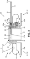
- the headrest 10 comprises a locking device 30 in which a control rod 31 is configured to be actuated by the user so as to move between a locked position in which the resting part 20 is prevented from moving with respect to the mounting part 11, and an adjustment position in which the resting part 20 is allowed to move with respect to the mounting part 11.
- the control rod 31 is straight and extends along a central axis C between a first end 31a, intended to be flush with an outer surface of the cushion 25 to enable actuation by the user 1, and a second end 31a.
- the control rod 31 presents an adjusting portion 32 having a cross-section that differs from the cross-section of the remaining of the control rod 31.
- the cross-section of the adjusting portion 32 is reduced with respect to that of the remaining of the control rod 31, and especially at least with respect to portions adjacent the adjusting portion 32.
- the cross-section of the control rod 31 is circular except for the adjusting portion 32 where two diametrically opposite notches are formed.
- the adjusting portion 32 hence presents two parallel flats 33 providing an oblong cross-section with two straight long sides and two arcuate short sides. Adjacent the adjusting portion 32 towards the second end 31b, the control rod 31 presents a locking portion 34 which has the same cross-section as that of the remaining of the control rod 31.
- the arrangement and conformation of the locking 34 and adjusting 32 portions of the control rod 31 are adapted to the way the locking device 30 operates in the disclosed embodiment, as it will become apparent from the following of the description. In variants where the locking device 30 would operate in a different way, the arrangement and conformation of the locking 34 and adjusting 32 portions of the control rod 31 could be adapted accordingly.
- the control rod 31 is mounted on the resting part 20 so as to move along with the resting part in rotation about the pivot axis.
- a wing bracket 24 is secured to an outer surface, opposite the wall 18 of the bracket 16 of the mounting part 11, of the first branch 22a of one of the wings 22 of the frame 21.
- the control rod is mounted on the wing bracket and through the first branch of the wing so as to be movable with respect to the resting part in translation along its central axis.
- the wall 18 of the bracket 16 of the mounting part 11 facing the first branch 22a of the wing 22 carrying the control rod 31 comprises a slot 35 through which the control rod 31 extends.
- the slot 35 is globally arcuate with a radius corresponding to a radius of an arcuate path around the pivot axis P along which the control rod 31 runs as the resting part 20 is moved between the forward most position and the rearward most position.
- the slot 35 includes three adjacent through-openings 36 and arcuate connection portions 37 each connecting two through-openings 36 with each other.
- Each of the through-openings 36 is configured to receive the locking portion 34 of the control rod 31 whereas each of the arcuate connection portion is configured to receive the adjusting portion 32 of the control rod 31 but not the locking portion 34.
- the control rod 31 engages any of the through-openings 36 of the mounting part 11 so as to have a contact surface, arranged peripherically on the locking portion 34, in contact with an abutment surface, borne internally by the through-opening 36, thereby preventing the resting part 20 from pivoting.
- the through-openings 36 hence define a plurality of separate abutment surfaces spaced apart from each other and arranged in correspondence with the arcuate path of the contact surface of the locking portion 34 of the control rod 31.
- the plurality of separate abutment surfaces comprises two end abutment surfaces, defining respectively the forward most position and the rearward most position, and one intermediate abutment surface defining an intermediate position between the forward most position and the rearward most position.
- any suitable number of intermediate positions could be defined through the arrangement of any corresponding number of intermediate abutment surfaces.
- the contact surface of the locking portion 34 of the control rod 31 is spaced apart from the abutment surface of the mounting part 11, and the adjusting portion 32 of the control rod 31 is engaged in the slot 35.
- the adjusting portion 32 of the control rod 31 may then slide freely in the slot 35 of the mounting part 11 as the resting part 20 is pivoted.
- the control rod 31 is moved in translation along its central axis C between the locked and adjustment positions.
- the control rod 31 is urged towards the locked position.
- the locking device 30 comprises a return member, in the form of a compression spring 40, arranged in the wing bracket 24, between the first branch 22a of the wing 22 and a flange on the control rod 31, so that in an extended state to which it is elastically returned, the control rod 31 is in the locked position, and in a compressed state, the control rod 31 is in the adjusting position.
- the headrest 10 further comprises an urging device 45 configured to urge the resting part 20 towards the forward most position.
- the urging device 45 comprises an elastically deformable member arranged between the mounting part 11 and the resting part 20 to elastically return the resting part 20 towards the forward most position.
- the elastically deformable member is a tension spring 46 having opposite ends attached respectively to the anchoring element 23 of the wing 22 of the resting part 20 and to an anchoring element 47 arranged on an outer surface of the bracket 16 of the mounting part 11.
- the anchoring elements 23, 47 of the wing 22 and the bracket 16 are spaced apart of a distance which is minimum when the resting part 20 is in the forward most position and which increases as the resting part 20 is moved towards the rearward most position.
- the tension spring 46 extends and exerts a return force on the resting part 20. As soon as the resting part 20 is free of any external force, including a force exerted by the control rod 31 in the locked position, it is returned to the forward most position by the tension spring 46.
- the control rod 31 is in the locked position with the contact surface of its locking portion 34 against the abutment surface of one of the through-openings 36.
- the user 1 actuates the control rod 31 by pushing its first end 31a.
- the control rod 31 translates along its central axis C to its adjustment position where its adjusting portion 32 faces the arcuate connection portion 37.
- the adjusting portion 32 enters the arcuate connection portion 37 and any subsequent through-opening 36 or arcuate connection portion 37 until the resting part 20 reaches the forward most position as shown in figures 7 and 8 .
- the user 1 may release the control rod 31 which is returned to the locked position with the locking portion 34 engaged within the corresponding through-opening 36.
- the user 1 wants the headrest 10 to be in the intermediate position, he keeps on pushing the control rod 31 or push it once again so that it reaches the adjustment position with the adjusting portion 32 facing the arcuate connection portion 37, as shown in figure 9 .
- the user 1 can act on the resting part 20 especially by pushing it rearward with his head so that the adjusting portion 32 runs in the arcuate connection portion 37.
Priority Applications (2)
| Application Number | Priority Date | Filing Date | Title |
|---|---|---|---|
| EP22161842.4A EP4245604A1 (de) | 2022-03-14 | 2022-03-14 | Kopfstütze, sitz, fahrzeug und verfahren zum einstellen einer kopfstütze |
| US18/118,197 US20230286429A1 (en) | 2022-03-14 | 2023-03-07 | Headrest, seat, vehicle, and method for adjusting a position of a headrest |
Applications Claiming Priority (1)
| Application Number | Priority Date | Filing Date | Title |
|---|---|---|---|
| EP22161842.4A EP4245604A1 (de) | 2022-03-14 | 2022-03-14 | Kopfstütze, sitz, fahrzeug und verfahren zum einstellen einer kopfstütze |
Publications (1)
| Publication Number | Publication Date |
|---|---|
| EP4245604A1 true EP4245604A1 (de) | 2023-09-20 |
Family
ID=80738705
Family Applications (1)
| Application Number | Title | Priority Date | Filing Date |
|---|---|---|---|
| EP22161842.4A Pending EP4245604A1 (de) | 2022-03-14 | 2022-03-14 | Kopfstütze, sitz, fahrzeug und verfahren zum einstellen einer kopfstütze |
Country Status (2)
| Country | Link |
|---|---|
| US (1) | US20230286429A1 (de) |
| EP (1) | EP4245604A1 (de) |
Families Citing this family (1)
| Publication number | Priority date | Publication date | Assignee | Title |
|---|---|---|---|---|
| CN114174112A (zh) * | 2019-08-07 | 2022-03-11 | 沃尔沃卡车集团 | 用于车辆座椅的头枕 |
Citations (5)
| Publication number | Priority date | Publication date | Assignee | Title |
|---|---|---|---|---|
| WO1992004847A1 (en) * | 1990-09-20 | 1992-04-02 | Dellanno Ronald P | Apparatus for preventing whiplash |
| US20120068517A1 (en) * | 2010-09-17 | 2012-03-22 | Lear Corporation | Adjustable head restraint assembly for vehicle seats |
| JP2012250645A (ja) * | 2011-06-03 | 2012-12-20 | Ts Tech Co Ltd | ヘッドレスト |
| US20130193736A1 (en) * | 2010-12-24 | 2013-08-01 | Ts Tech Co., Ltd. | Headrest fore-aft position adjuster |
| WO2021023730A1 (en) | 2019-08-07 | 2021-02-11 | Volvo Truck Corporation | A headrest for a vehicle seat |
-
2022
- 2022-03-14 EP EP22161842.4A patent/EP4245604A1/de active Pending
-
2023
- 2023-03-07 US US18/118,197 patent/US20230286429A1/en active Pending
Patent Citations (5)
| Publication number | Priority date | Publication date | Assignee | Title |
|---|---|---|---|---|
| WO1992004847A1 (en) * | 1990-09-20 | 1992-04-02 | Dellanno Ronald P | Apparatus for preventing whiplash |
| US20120068517A1 (en) * | 2010-09-17 | 2012-03-22 | Lear Corporation | Adjustable head restraint assembly for vehicle seats |
| US20130193736A1 (en) * | 2010-12-24 | 2013-08-01 | Ts Tech Co., Ltd. | Headrest fore-aft position adjuster |
| JP2012250645A (ja) * | 2011-06-03 | 2012-12-20 | Ts Tech Co Ltd | ヘッドレスト |
| WO2021023730A1 (en) | 2019-08-07 | 2021-02-11 | Volvo Truck Corporation | A headrest for a vehicle seat |
Also Published As
| Publication number | Publication date |
|---|---|
| US20230286429A1 (en) | 2023-09-14 |
Similar Documents
| Publication | Publication Date | Title |
|---|---|---|
| US6334643B1 (en) | Vehicle seat | |
| US10065535B1 (en) | Seatback lift mechanism for a supine motor vehicle seating assembly | |
| US8172320B2 (en) | Impact absorption block for vehicle seatback assembly | |
| EP3372444B1 (de) | Mechanismus für eine liegende kraftfahrzeugsitzanordnung | |
| US20100066116A1 (en) | Deceleration responsive vehicle seat | |
| EP1368210B1 (de) | Sicherheitskopfstütze für kraftfahrzeug | |
| US8727437B2 (en) | Actuator for crash activated head restraint | |
| US7918501B1 (en) | Vehicle safety seat | |
| US20230286429A1 (en) | Headrest, seat, vehicle, and method for adjusting a position of a headrest | |
| US20040100133A1 (en) | Headrest seat-back arrangement | |
| EP1470023B1 (de) | Fahrzeugsitz mit kopfstütze welche unabhängig von der rückenlehne ist | |
| US20110227377A1 (en) | Mechatronic vehicle safety seat | |
| US8276983B2 (en) | Manual retracting head restraint | |
| CN110325398B (zh) | 交通工具座椅 | |
| HUT78065A (hu) | Ülés és azzal felszerelt jármű | |
| EP2058165B1 (de) | Sitzrückhaltevorrichtung | |
| CN111942235A (zh) | 用于车辆座椅的悬架系统 | |
| EP4010224B1 (de) | Rückenlehne für einen fahrzeugsitz | |
| EP0571097B1 (de) | Fahrzeugsitze | |
| CN110884399B (zh) | 机动车辆座椅 | |
| KR101694020B1 (ko) | 목 상해 저감 성능이 향상되는 차량용 시트 | |
| KR100551844B1 (ko) | 리트랙터와 웨빙을 이용한 자동차용 액티브 헤드레스트 | |
| WO2023104847A1 (en) | A tiltable head restraint | |
| EP2492139A1 (de) | Auslösermechanismus für ein aktives Kopfstützensystem und Sitzlehne | |
| CN112009327A (zh) | 机动车辆座椅 |
Legal Events
| Date | Code | Title | Description |
|---|---|---|---|
| PUAI | Public reference made under article 153(3) epc to a published international application that has entered the european phase |
Free format text: ORIGINAL CODE: 0009012 |
|
| STAA | Information on the status of an ep patent application or granted ep patent |
Free format text: STATUS: THE APPLICATION HAS BEEN PUBLISHED |
|
| AK | Designated contracting states |
Kind code of ref document: A1 Designated state(s): AL AT BE BG CH CY CZ DE DK EE ES FI FR GB GR HR HU IE IS IT LI LT LU LV MC MK MT NL NO PL PT RO RS SE SI SK SM TR |
|
| STAA | Information on the status of an ep patent application or granted ep patent |
Free format text: STATUS: REQUEST FOR EXAMINATION WAS MADE |
|
| 17P | Request for examination filed |
Effective date: 20231107 |
|
| RBV | Designated contracting states (corrected) |
Designated state(s): AL AT BE BG CH CY CZ DE DK EE ES FI FR GB GR HR HU IE IS IT LI LT LU LV MC MK MT NL NO PL PT RO RS SE SI SK SM TR |