EP4245570B1 - Reifen - Google Patents
Reifen Download PDFInfo
- Publication number
- EP4245570B1 EP4245570B1 EP23155119.3A EP23155119A EP4245570B1 EP 4245570 B1 EP4245570 B1 EP 4245570B1 EP 23155119 A EP23155119 A EP 23155119A EP 4245570 B1 EP4245570 B1 EP 4245570B1
- Authority
- EP
- European Patent Office
- Prior art keywords
- shoulder
- tire
- sipes
- chamfered portion
- land region
- Prior art date
- Legal status (The legal status is an assumption and is not a legal conclusion. Google has not performed a legal analysis and makes no representation as to the accuracy of the status listed.)
- Active
Links
Images


Classifications
-
- B—PERFORMING OPERATIONS; TRANSPORTING
- B60—VEHICLES IN GENERAL
- B60C—VEHICLE TYRES; TYRE INFLATION; TYRE CHANGING; CONNECTING VALVES TO INFLATABLE ELASTIC BODIES IN GENERAL; DEVICES OR ARRANGEMENTS RELATED TO TYRES
- B60C11/00—Tyre tread bands; Tread patterns; Anti-skid inserts
- B60C11/03—Tread patterns
- B60C11/0306—Patterns comprising block rows or discontinuous ribs
-
- B—PERFORMING OPERATIONS; TRANSPORTING
- B60—VEHICLES IN GENERAL
- B60C—VEHICLE TYRES; TYRE INFLATION; TYRE CHANGING; CONNECTING VALVES TO INFLATABLE ELASTIC BODIES IN GENERAL; DEVICES OR ARRANGEMENTS RELATED TO TYRES
- B60C11/00—Tyre tread bands; Tread patterns; Anti-skid inserts
- B60C11/01—Shape of the shoulders between tread and sidewall, e.g. rounded, stepped or cantilevered
-
- B—PERFORMING OPERATIONS; TRANSPORTING
- B60—VEHICLES IN GENERAL
- B60C—VEHICLE TYRES; TYRE INFLATION; TYRE CHANGING; CONNECTING VALVES TO INFLATABLE ELASTIC BODIES IN GENERAL; DEVICES OR ARRANGEMENTS RELATED TO TYRES
- B60C11/00—Tyre tread bands; Tread patterns; Anti-skid inserts
- B60C11/03—Tread patterns
- B60C11/0302—Tread patterns directional pattern, i.e. with main rolling direction
-
- B—PERFORMING OPERATIONS; TRANSPORTING
- B60—VEHICLES IN GENERAL
- B60C—VEHICLE TYRES; TYRE INFLATION; TYRE CHANGING; CONNECTING VALVES TO INFLATABLE ELASTIC BODIES IN GENERAL; DEVICES OR ARRANGEMENTS RELATED TO TYRES
- B60C11/00—Tyre tread bands; Tread patterns; Anti-skid inserts
- B60C11/03—Tread patterns
- B60C11/0304—Asymmetric patterns
-
- B—PERFORMING OPERATIONS; TRANSPORTING
- B60—VEHICLES IN GENERAL
- B60C—VEHICLE TYRES; TYRE INFLATION; TYRE CHANGING; CONNECTING VALVES TO INFLATABLE ELASTIC BODIES IN GENERAL; DEVICES OR ARRANGEMENTS RELATED TO TYRES
- B60C11/00—Tyre tread bands; Tread patterns; Anti-skid inserts
- B60C11/03—Tread patterns
- B60C11/0327—Tread patterns characterised by special properties of the tread pattern
- B60C11/033—Tread patterns characterised by special properties of the tread pattern by the void or net-to-gross ratios of the patterns
-
- B—PERFORMING OPERATIONS; TRANSPORTING
- B60—VEHICLES IN GENERAL
- B60C—VEHICLE TYRES; TYRE INFLATION; TYRE CHANGING; CONNECTING VALVES TO INFLATABLE ELASTIC BODIES IN GENERAL; DEVICES OR ARRANGEMENTS RELATED TO TYRES
- B60C11/00—Tyre tread bands; Tread patterns; Anti-skid inserts
- B60C11/03—Tread patterns
- B60C11/12—Tread patterns characterised by the use of narrow slits or incisions, e.g. sipes
- B60C11/1236—Tread patterns characterised by the use of narrow slits or incisions, e.g. sipes with special arrangements in the tread pattern
-
- B—PERFORMING OPERATIONS; TRANSPORTING
- B60—VEHICLES IN GENERAL
- B60C—VEHICLE TYRES; TYRE INFLATION; TYRE CHANGING; CONNECTING VALVES TO INFLATABLE ELASTIC BODIES IN GENERAL; DEVICES OR ARRANGEMENTS RELATED TO TYRES
- B60C11/00—Tyre tread bands; Tread patterns; Anti-skid inserts
- B60C11/03—Tread patterns
- B60C11/12—Tread patterns characterised by the use of narrow slits or incisions, e.g. sipes
- B60C11/1259—Depth of the sipe
- B60C11/1263—Depth of the sipe different within the same sipe
-
- B—PERFORMING OPERATIONS; TRANSPORTING
- B60—VEHICLES IN GENERAL
- B60C—VEHICLE TYRES; TYRE INFLATION; TYRE CHANGING; CONNECTING VALVES TO INFLATABLE ELASTIC BODIES IN GENERAL; DEVICES OR ARRANGEMENTS RELATED TO TYRES
- B60C11/00—Tyre tread bands; Tread patterns; Anti-skid inserts
- B60C11/03—Tread patterns
- B60C11/12—Tread patterns characterised by the use of narrow slits or incisions, e.g. sipes
- B60C11/1272—Width of the sipe
- B60C11/1281—Width of the sipe different within the same sipe, i.e. enlarged width portion at sipe bottom or along its length
-
- B—PERFORMING OPERATIONS; TRANSPORTING
- B60—VEHICLES IN GENERAL
- B60C—VEHICLE TYRES; TYRE INFLATION; TYRE CHANGING; CONNECTING VALVES TO INFLATABLE ELASTIC BODIES IN GENERAL; DEVICES OR ARRANGEMENTS RELATED TO TYRES
- B60C11/00—Tyre tread bands; Tread patterns; Anti-skid inserts
- B60C11/03—Tread patterns
- B60C11/13—Tread patterns characterised by the groove cross-section, e.g. for buttressing or preventing stone-trapping
- B60C11/1376—Three dimensional block surfaces departing from the enveloping tread contour
- B60C11/1392—Three dimensional block surfaces departing from the enveloping tread contour with chamfered block edges
-
- B—PERFORMING OPERATIONS; TRANSPORTING
- B60—VEHICLES IN GENERAL
- B60C—VEHICLE TYRES; TYRE INFLATION; TYRE CHANGING; CONNECTING VALVES TO INFLATABLE ELASTIC BODIES IN GENERAL; DEVICES OR ARRANGEMENTS RELATED TO TYRES
- B60C11/00—Tyre tread bands; Tread patterns; Anti-skid inserts
- B60C11/03—Tread patterns
- B60C2011/0337—Tread patterns characterised by particular design features of the pattern
- B60C2011/0386—Continuous ribs
- B60C2011/039—Continuous ribs provided at the shoulder portion
Definitions
- the present invention relates to a tire.
- Patent Literature 1 Japanese Unexamined Patent Application No. 2021-104746 has proposed a tire having a shoulder land region provided with a plurality of shoulder sipes. Tires similar with respect to said shoulder land regions are also disclosed in US 2017/015143 A1 , US 2018/009269 A1 , and US 2019/375244 A1 , respectively.
- the present invention was made in view of the above, and a primary object thereof is to provide a tire with improved cornering performance while suppressing deterioration of the noise performance.
- the present invention is a tire having a tread portion including a first tread edge, a plurality of circumferential grooves extending continuously in a tire circumferential direction, and a first shoulder land region, wherein
- the tire of the present invention improves the cornering performance while suppressing the deterioration of the noise performance.
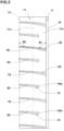
- FIG. 1 is a developed view of a tread portion 2 of a tire 1 of the present embodiment.
- the tire 1 of the present embodiment is suitable for use as a pneumatic tire for passenger cars, for example.
- the present invention is not limited to such an aspect, and may be applied to heavy-duty pneumatic tires and non-pneumatic tires that are not filled with pressurized air.
- the tire 1 of the present invention has a tread portion 2 of which position for mounting the tire on a vehicle is specified regarding inner and outer sides of the tread portion with respect to the vehicle.
- the tread portion 2 includes a first tread edge T1, which is on the outer side of the vehicle when the tire 1 is mounted on the vehicle, and a second tread edge T2, which is on the inner side of the vehicle when the tire 1 is mounted on the vehicle.
- the mounting position to the vehicle is indicated by characters or symbols on a sidewall portion (not shown), for example.
- the tire 1 of the present invention is not limited to such a manner.
- the first tread edge T1 and the second tread edge T2 are the outermost ground contact positions in a tire axial direction of the tire 1 when the tire 1 in a standard state is in contact with a flat surface with zero camber angle by being loaded with 60% of a standard tire load.
- standard state refers to a state in which the tire 1 is mounted on a standard rim (not shown), inflated to a standard inner pressure, and loaded with no tire load.
- the standard state means a standard state of use according to the purpose of use of the tire loaded with no tire load.
- dimensions of various parts of the tire are values measured in the standard state. Further, in the present specification, unless otherwise noted, known methods can be applied as appropriate to measure the aforementioned dimensions and composition of materials.
- standard rim refers to a wheel rim specified for the concerned tire by a standard included in a standardization system on which the tire is based, for example, the "normal wheel rim” in JATMA, "Design Rim” in TRA, and “Measuring Rim” in ETRTO.
- standard inner pressure refers to air pressure specified for the concerned tire by a standard included in a standardization system on which the tire is based, for example, the maximum air pressure in JATMA, maximum value listed in the "TIRE LOAD LIMITS AT VARIOUS COLD INFLATION PRESSURES" table in TRA, and "INFLATION PRESSURE” in ETRTO.
- standard tire load refers to a tire load specified for the concerned tire by a standard included in a standardization system on which the tire is based, for example, the “maximum load capacity” in JATMA, maximum value listed in “TIRE LOAD LIMITS AT VARIOUS COLD INFLATION PRESSURES" table in TRA, and "LOAD CAPACITY” in ETRTO.
- standard tire load refers to the maximum applicable load for the use of the tire according to the above-mentioned standards.
- the tread portion 2 includes a plurality of circumferential grooves 3 extending continuously in a tire circumferential direction between the first tread edge T1 and the second tread edge T2, and a plurality of land regions 4 divided by the circumferential grooves 3.
- the tire 1 of the present embodiment is configured as a so-called five-rib tire where the tread portion 2 is divided by four circumferential grooves 3 into five land regions 4.
- the tire 1 of the present invention is not limited to such a mode, but may be configured, for example, as a so-called four-rib tire having the tread portion 2 divided into four land regions 4 by three circumferential grooves 3.
- the circumferential grooves 3 include a first shoulder circumferential groove 5.
- the first shoulder circumferential groove 5 is arranged closest to the first tread edge T1 among the multiple circumferential grooves 3.
- the circumferential grooves 3 include a second shoulder circumferential groove 6, a first crown circumferential groove 7 and a second crown circumferential groove 8.
- the second shoulder circumferential groove 6 is arranged closest to the second tread edge T2 among the multiple circumferential grooves 3.
- the first crown circumferential groove 7 is arranged between the first shoulder circumferential groove 5 and a tire equator (C).
- the second crown circumferential groove 8 is arranged between the second shoulder circumferential groove 6 and the tire equator (C).
- a distance L1 from the tire equator (C) to a groove centerline of the first shoulder circumferential groove 5 or the second shoulder circumferential groove 6 is 25% or more and 35% or less of a tread width TW. It is preferred that a distance L2 from the tire equator (C) to a groove centerline of the first crown circumferential groove 7 or the second crown circumferential groove 8 is 5% or more and 15% or less of the tread width TW. It should be noted that the tread width TW is the distance in the tire axial direction from the first tread edge T1 to the second tread edge T2 of the tire 1 in the standard state.
- the land regions 4 of the present invention include a first shoulder land region 11.
- the first shoulder land region 11 is demarcated axially outside the first shoulder circumferential groove 5 and includes the first tread edge T1.
- the land regions 4 in the present embodiment include a second shoulder land region 12, a first middle land region 13, a second middle land region 14, and a crown land region 15.
- the second shoulder land region 12 is demarcated axially outside the second shoulder circumferential groove 6 and includes the second tread edge T2.
- the first middle land region 13 is demarcated between the first shoulder circumferential groove 5 and the first crown circumferential groove 7.
- the second middle land region 14 is demarcated between the second shoulder circumferential groove 6 and the second crown circumferential groove 8.
- the crown land region 15 is demarcated between the first crown circumferential groove 7 and the second crown circumferential groove 8.
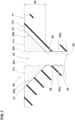
- FIG. 2 shows an enlarged view of the first shoulder land region 11.
- the first shoulder land region 11 includes a first longitudinal edge 16 located on the first shoulder circumferential groove 5 side and a shoulder center position (11c), which is the center position in the tire axial direction between the first longitudinal edge 16 and the first tread edge T1. Further, the first shoulder land region 11 is provided with a plurality of first shoulder sipes 18 extending from the first longitudinal edge 16 to at least the first tread edge T1.
- the term "sipe” means a groove-shaped body having a small width (a concept that includes grooves and sipes), where the width between the two inner walls is 2.0 mm or less in the area excluding chamfered portions, which will be described later. Further, the area excluding the chamfered portions means the area where the two inner walls extend in a tire radial direction parallel to each other. The term “parallel” means that an angle between the two inner walls is 10 degrees or less. The width between the two inner walls in the area excluding the chamfered portions is preferably 1.5 mm or less, and in a more preferred manner from 0.4 to 1.0 mm.
- an overall depth of each of the sipes is 3.0 mm or more and 5.5 mm or less, for example.
- the sipes may also have a so-called flask bottom with an increased width at the bottom. It should be noted that in the present specification, if one of the groove shaped bodies has a portion with the width exceeding 2.0 mm over more than 50% of the overall depth thereof, the one of the groove shaped bodies shall be regarded as a groove.
- FIG. 3 shows an enlarged view of one of the first shoulder sipes 18.
- FIG. 4 shows a cross-sectional view taken along A-A line of FIG. 3 .
- FIG. 5 shows a cross-sectional view taken along B-B line of FIG. 3 .
- each of the first shoulder sipes 18 in the present invention has a chamfered portion 20 in the entire lengthwise range from the first longitudinal edge 16 to the first tread edge T1.
- the chamfered portion 20 is formed by sloped surfaces (20a) provided in both of the two sipe walls, but the chamfered portion 20 of the present invention may also be formed by the sloped surface (20a) provided in only one of the two sipe walls.
- Each of the chamfered portions 20 includes a first chamfered portion 21 demarcated between the shoulder center position (11c) and the first longitudinal edge 16 and a second chamfered portion 22 demarcated between the shoulder center position (11c) and the first tread edge T1.
- the second chamfered portion 22 has a chamfer volume V2 smaller than a chamfer volume V1 of the first chamfered portion 21.
- FIG. 6 shows an enlarged cross-sectional view of a conventional sipe (a) without a chamfered portion in a state of contacting a road surface (G).
- FIG. 6 shows a state during braking, with an arrow (R) indicating a tire rotational direction and an arrow (A) indicating a tire running direction.
- R arrow
- A arrow
- FIG. 6 in general, when a large shearing force (braking force in FIG.
- each of the first shoulder sipes 18 is provided with the chamfered portion 20 throughout the entire lengthwise range from the first longitudinal edge 16 to the first tread edge T1. Therefore, it is possible that the tire 1 of the present invention suppresses the above-described problems and improves the braking performance and the cornering performance. Further, in the present invention, since the chamfer volume V1 of the first chamfered portion 21 is relatively large, a sufficient size of the chamfered portion can be secured on the first longitudinal edge 16 side of the first shoulder land region 11. As a result, in the formation range of the first chamfered portion 21 of the first shoulder sipes 18, a ground contacting property is further improved, therefore, the cornering performance can be expected to be further improved.
- the relatively small chamfer volume V2 of the second chamfered portion 22 can suppress an increase in noise due to the increase in the sipe volume because of the chamfered portion 20, thereby, it is possible that the deterioration of the noise performance is suppressed.
- FIG. 7 shows an enlarged cross-sectional view of one of the chamfered portions 20.
- each of the chamfered portions 20 in the present embodiment includes the sloped surfaces (20a) each inclined to connect a main body (25a) of a respective one of sipe walls 25 with a ground contacting surface (11s) of the first shoulder land region 11 so that sharp corners are not formed between the sipe walls 25 of each of the first shoulder sipes 18 and the ground contacting surface (11s) of the first shoulder land region 11.
- Each of the sloped surfaces (20a) in the present embodiment is planar (that is, straight in the lateral cross-section of the sipe), but each of the sloped surfaces (20a) may be smoothly curved so as to be convex radially outward, or may have a plurality of micro planar surfaces between the main body (25a) and the ground contacting surface (11s), or may be a combination of a micro-plane (or micro planes) and a micro-curved surface (or micro-curved surfaces) between the main body (25a) and the ground contacting surface (11s). Further, an opening width of each of the chamfered portions 20 may exceed 2.0 mm, for example. Each of the chamfered portions 20 has a depth (d2) of 10% or more and 40% or less of an overall depth (d1) (shown in FIG. 4 ) of each of the first shoulder sipes 18, for example.
- the chamfer volume is defined as follows. That is, in the case that each of the first shoulder sipes 18 has the chamfered portion on one of the sipe walls thereof, the chamfer volume is the volume of the portion surrounded by a virtual ground contacting surface (11v) and a virtual sipe wall (25v).
- the virtual ground contacting surface (11v) is obtained by extending the ground contacting surface (11s) of the first shoulder land region 11 in a direction of the opening width of the first shoulder sipe 18.
- the virtual sipe wall (25v) is obtained by extending the main body (25a) of the sipe wall 25 to the virtual ground contacting surface (11v).
- the chamfer volume is the sum of the volumes of the two portions shaded with dots.
- Each of the sloped surfaces (20a) of the chamfered portion 20 means a surface from the main body (25a) of a respective one of the sipe walls 25 to the ground contacting surface (1 1s) of the first shoulder land region 11. It should be noted that, when the tire 1 in the standard state is in contact with a flat surface with zero camber angle by being loaded with 60% of the standard tire load, an edge of the outer surface of the first shoulder land region 11 contacting the plane is a boundary 27 between each of the sloped surfaces (20a) and the ground contacting surface (11s).
- the virtual ground contacting surface (11v) is a virtual surface obtained by extending the ground contacting surface (11s) from the boundary 27 in the opening width direction of the sipe.
- the virtual ground contacting surface (11v) corresponds to a curved line extending from the boundary 27 while maintaining the curvature of the ground contacting surface (11s).
- the virtual sipe wall (25v) is a virtual surface obtained by extending the main body (25a) of each of the sipe walls 25 from a boundary 28 between the main body (25a) and a respective one of the sloped surfaces (20a) to the virtual ground contacting surface (11v).
- the boundary 28 between the main body (25a) of each of the sipe walls 25 and a respective one of the sloped surfaces (20a) is a location where the angle of the sipe wall 25 with respect to the tire radial direction changes abruptly. It should be noted that if the location where the angle changes abruptly is a region having a substantial width, the position closest to the groove centerline corresponds to the boundary 28.
- the ground contacting surface (11s) of the first shoulder land region 11 in the present embodiment is provided with only sipes and not provided with grooves between the first longitudinal edge 16 and the first tread edge T1. Thereby, the cornering performance is further improved.
- the present invention is not limited to such an aspect, and the ground contacting surface (11s) of the first shoulder land region 11 may be provided with grooves.
- an angle of each of the first shoulder sipes 18 (an angle on the acute angle side) with respect to the tire circumferential direction increases continuously from the first longitudinal edge 16 to the first tread edge T1. Therefore, the cornering performance and the breaking performance are improved in a good balance.
- an angle ⁇ 1 of each of the first shoulder sipes 18 with respect to the tire circumferential direction is preferably 30 degrees or more, more preferably 50 degrees or more, still more preferably 60 degrees or more, and preferably 80 degrees or less, more preferably 70 degrees or less.
- the angle ⁇ 1 is about 70 to 80 degrees, but the angle ⁇ 1 is not limited to this, and may be from 30 to 70 degrees in another embodiment.
- the first shoulder sipes 18 configured as such can provide a large frictional force in the tire axial direction on the first longitudinal edge 16 side, therefore, it is possible that the cornering performance is further improved.
- an angle ⁇ 2 of each of the first shoulder sipes 18 with respect to the tire circumferential direction is 60 degrees or more and 90 degrees or less, and preferably 80 degrees or more and 90 degrees or less, for example.
- each of the chamfered portions 20 has a cross-sectional area taken perpendicular to a longitudinal direction of the sipe and increasing (continuously in the present embodiment) axially inward.
- the cross-sectional area increases continuously from the first tread edge T1 to the first longitudinal edge 16.
- the chamfer volume V2 of each of the second chamfered portions 22 is 20% or more, more preferably 30% or more, even more preferably 40% or more, and 70% or less, more preferably 60% or less, even more preferably 50% or less of the chamfer volume V1 of each of the first chamfered portions 21.
- each of the two sipe walls 25 in the present embodiment includes a sloped surface (20a), therefore, each of the chamfered portions 20 includes two sloped surfaces (20a) and these two sloped surfaces (20a) have a symmetrical shape with respect to a sipe centerline in a cross section of the sipe.
- the sloped surfaces (20a) are not limited to such a mode, and these two sloped surfaces (20a) may have different shapes from each other, for example.
- Each of the sloped surfaces (20a) has an angle of 20 degrees or more and 70 degrees or less with respect to the tire radial direction, for example. Further, each of the sloped surfaces (20a) in the first chamfered portion 21 has an angle ⁇ 3 with respect to the tire radial direction larger than an angle ⁇ 4 of each of the sloped surfaces (20a) in the second chamfered portion 22 with respect to the tire radial direction. Thereby, it is possible that the cornering performance is further improved.
- the first shoulder land region 11 in the present embodiment is provided with a plurality of shoulder terminating sipes 30.
- Each of the shoulder terminating sipes 30 extends at least from the first tread edge T1 toward the first longitudinal edge 16 and has a terminating end (30a) as a closed end not connected with other sipes and grooves in the ground contacting surface (11s) of the first shoulder land region 11.
- Each of the shoulder terminating sipes 30 is formed with a chamfered portion 31 over the entire lengthwise range thereof from the first tread edge T1 to the terminating end (30a).
- each of the shoulder terminating sipes 30 has a cross-sectional area taken perpendicular to a longitudinal direction of the sipe and continuously increasing from the first tread edge T1 to the terminating end (30a). It is possible that the shoulder terminating sipes 30 configured as such, together with the first shoulder sipes 18 described above, improve the cornering performance while suppressing deterioration of the noise performance.
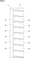
- FIG. 8 shows an enlarged view of the second shoulder land region 12.
- the second shoulder land region 12 in the present embodiment is provided with a plurality of second shoulder sipes 35.
- Each of the second shoulder sipes 35 extends from the second tread edge T2 to the second shoulder circumferential groove 6.
- Each of the second shoulder sipes 35 has a chamfered portion 36 formed over the entire lengthwise range from the second shoulder circumferential groove 6 to the second tread edge T2.
- the configuration of the chamfered portions 20 of the first shoulder sipes 18 described above can be applied to the chamfered portions 36 of the second shoulder sipes 35, and the description here is omitted.
- the tire 1 of the present embodiment can further enhance the above-described effects.
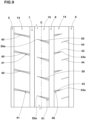
- FIG. 9 shows an enlarged view of the first middle land region 13, the second middle land region 14, and the crown land region 15.
- the first middle land region 13 is provided with first middle sipes 40 each completely crossing the ground contacting surface of the first middle land region 13 in the tire axial direction.
- each of the first middle sipes 40 is formed with a chamfered portion 41 over the entire lengthwise range thereof.
- the chamfered portion 41 of each of the first middle sipes 40 has a cross-sectional area taken perpendicular to a longitudinal direction of the sipe and continuously increasing from an axial center of the sipe toward both sides in the tire axial direction. It is possible that the first middle sipes 40 configured as such, together with the above-mentioned first shoulder sipes 18, improve the cornering performance and the braking performance in a good balance.
- the second middle land region 14 is provided with a plurality of outer second middle sipes 43 and a plurality of inner second middle sipes 44.
- Each of the outer second middle sipes 43 extends axially outward from the second crown circumferential groove 8 to have a terminating end (43a) as a closed end not connected with other sipes and grooves in the ground contacting surface of the second middle land region 14.
- Each of the inner second middle sipes 44 extends axially inward from the second shoulder circumferential groove 6 to have a closed terminating end not connected with other sipes and grooves in the ground contacting surface of the second middle land region 14.
- Each of the outer second middle sipes 43 is formed with a chamfered portion 46 over the entire lengthwise range thereof.
- the chamfered portion 46 of each of the outer second middle sipes 43 has a cross-sectional area taken perpendicular to a longitudinal direction of the sipe and decreasing (continuously in the present embodiment) from the second crown circumferential groove 8 toward the terminating end (43a).
- the inner second middle sipes 44 are not chamfered. It is possible that the outer second middle sipes 43 and the inner second middle sipes 44 configured as such improve the braking performance while suppressing the uneven wear in the land region.
- the crown land region 15 is provided with a plurality of crown sipes 50.
- Each of the crown sipes 50 extends from the second crown circumferential groove 8 toward the tire equator (C) to have a terminating end (50a) as a closed end not connected with other sipes and grooves within a ground contacting surface (15s) of the crown land region 15, for example.
- each of the crown sipes 50 is provided with a chamfered portion 51 over the entire lengthwise range thereof.
- the chamfered portion 51 of each of the crown sipes 50 has a cross-sectional area taken perpendicular to a longitudinal direction of the sipe and decreasing (continuously in the present embodiment) from the second crown circumferential groove 8 toward the terminating end (50a). It is possible that the crown sipes 50 configured as such improve the braking performance while suppressing the uneven wear in the land region.
- each of the land regions of the present embodiment is provided with only sipes and is not provided with a groove. Thereby, the cornering performance and the braking performance are still further improved.
Landscapes
- Engineering & Computer Science (AREA)
- Mechanical Engineering (AREA)
- Tires In General (AREA)
Claims (5)
- Reifen (1) mit einem Laufflächenabschnitt (2), umfassend:eine erste Laufflächenkante (T1);eine Vielzahl von Umfangsrillen (3, 5, 6, 7, 8), die sich kontinuierlich in einer Reifenumfangsrichtung erstrecken; undeinen ersten Schulterlandbereich (11), wobeidie Umfangsrillen (3, 5, 6, 7, 8) eine erste Schulterumfangsrille (5) umfassen, die sich kontinuierlich in der Reifenumfangsrichtung am nächsten zu der ersten Laufflächenkante (T1) unter den Umfangsrillen (3, 5, 6, 7, 8) erstreckt,der erste Schulterlandbereich (11) außerhalb der ersten Schulterumfangsrille (5) in einer Reifenaxialrichtung abgegrenzt ist und eine erste Längskante (16), die sich auf der Seite der ersten Schulterumfangsrille (5) befindet, und eine Schultermittelposition (11c) umfasst,die Schultermittelposition (11c) eine Mittelposition in der Reifenaxialrichtung zwischen der ersten Längskante (16) und der ersten Laufflächenkante (T1) ist,der erste Schulterlandbereich (11) mit einer Vielzahl von ersten Schulterfeinschnitten (18) versehen ist, die sich von der ersten Längskante (16) zu mindestens der ersten Laufflächenkante (T1) erstrecken,jeder der ersten Schulterfeinschnitte (18) mit einem angefasten Abschnitt (20, 21, 22) in einem gesamten Längsbereich von der ersten Längskante (16) zu der ersten Laufflächenkante (T1) versehen ist, wobei die Breite zwischen den zwei Innenwänden jedes ersten Schulterfeinschnitts (18) in dem Feinschnittbereich mit Ausnahme des angefasten Abschnitts 2,0 mm oder weniger beträgt,jeder der angefasten Abschnitte (20, 21, 22) einen ersten angefasten Abschnitt (21), der zwischen der Schultermittelposition (11c) und der ersten Längskante (16) definiert ist, und einen zweiten angefasten Abschnitt (22), der zwischen der Schultermittelposition (11c) und der ersten Laufflächenkante (T1) definiert ist, umfasst, undder zweite angefaste Abschnitt (22) ein Fasenvolumen (V2) aufweist, das kleiner als ein Fasenvolumen (V1) des ersten angefasten Abschnitts (21) ist,dadurch gekennzeichnet, dass
das Fasenvolumen (V2) des zweiten angefasten Abschnitts (22) 20 % oder mehr und 70 % oder weniger des Fasenvolumens (V1) des ersten angefasten Abschnitts (21) beträgt. - Reifen (1) nach Anspruch 1, wobei jeder der ersten Schulterfeinschnitte (18) einen Winkel in Bezug auf die Reifenumfangsrichtung aufweist, der kontinuierlich von der ersten Längskante (16) zu der ersten Laufflächenkante (T1) zunimmt.
- Reifen (1) nach einem der Ansprüche 1 bis 2, wobei jeder der ersten Schulterfeinschnitte (18) einen Winkel von 30 Grad oder mehr und 70 Grad oder weniger in Bezug auf die Reifenumfangsrichtung an der ersten Längskante (16) aufweist.
- Reifen (1) nach einem der Ansprüche 1 bis 3, wobei jeder der ersten Schulterfeinschnitte (18) einen Winkel von 80 Grad oder mehr und 90 Grad oder weniger in Bezug auf die Reifenumfangsrichtung an der ersten Laufflächenkante (T1) aufweist.
- Reifen (1) nach einem der Ansprüche 1 bis 4, wobei eine Bodenkontaktfläche des ersten Schulterlandbereichs (11) nur mit Feinschnitten zwischen der ersten Längskante (16) und der ersten Laufflächenkante (T1) versehen ist.
Applications Claiming Priority (1)
| Application Number | Priority Date | Filing Date | Title |
|---|---|---|---|
| JP2022039482A JP2023134123A (ja) | 2022-03-14 | 2022-03-14 | タイヤ |
Publications (2)
| Publication Number | Publication Date |
|---|---|
| EP4245570A1 EP4245570A1 (de) | 2023-09-20 |
| EP4245570B1 true EP4245570B1 (de) | 2024-12-25 |
Family
ID=85175758
Family Applications (1)
| Application Number | Title | Priority Date | Filing Date |
|---|---|---|---|
| EP23155119.3A Active EP4245570B1 (de) | 2022-03-14 | 2023-02-06 | Reifen |
Country Status (4)
| Country | Link |
|---|---|
| US (1) | US12358325B2 (de) |
| EP (1) | EP4245570B1 (de) |
| JP (1) | JP2023134123A (de) |
| CN (1) | CN116749684A (de) |
Family Cites Families (8)
| Publication number | Priority date | Publication date | Assignee | Title |
|---|---|---|---|---|
| JP2005075213A (ja) * | 2003-09-02 | 2005-03-24 | Bridgestone Corp | 空気入りタイヤ |
| US10688833B2 (en) * | 2015-06-12 | 2020-06-23 | Bridgestone Corporation | Tyre tread |
| JP6467309B2 (ja) * | 2015-07-16 | 2019-02-13 | 住友ゴム工業株式会社 | 空気入りタイヤ |
| JP6750358B2 (ja) * | 2016-07-11 | 2020-09-02 | 住友ゴム工業株式会社 | 空気入りタイヤ |
| JP7074561B2 (ja) * | 2018-05-17 | 2022-05-24 | Toyo Tire株式会社 | 空気入りタイヤ |
| JP7057226B2 (ja) * | 2018-06-06 | 2022-04-19 | Toyo Tire株式会社 | 空気入りタイヤ |
| JP7126869B2 (ja) * | 2018-06-06 | 2022-08-29 | Toyo Tire株式会社 | 空気入りタイヤ |
| JP7074120B2 (ja) | 2019-12-26 | 2022-05-24 | 住友ゴム工業株式会社 | タイヤ |
-
2022
- 2022-03-14 JP JP2022039482A patent/JP2023134123A/ja active Pending
-
2023
- 2023-02-06 EP EP23155119.3A patent/EP4245570B1/de active Active
- 2023-02-15 US US18/110,027 patent/US12358325B2/en active Active
- 2023-02-23 CN CN202310155743.5A patent/CN116749684A/zh active Pending
Also Published As
| Publication number | Publication date |
|---|---|
| US20230286324A1 (en) | 2023-09-14 |
| US12358325B2 (en) | 2025-07-15 |
| EP4245570A1 (de) | 2023-09-20 |
| JP2023134123A (ja) | 2023-09-27 |
| CN116749684A (zh) | 2023-09-15 |
Similar Documents
| Publication | Publication Date | Title |
|---|---|---|
| EP3015286B1 (de) | Luftreifen | |
| US10173476B2 (en) | Pneumatic tire | |
| US10981418B2 (en) | Tire | |
| CN107639975B (zh) | 轮胎 | |
| US20190160879A1 (en) | Tire | |
| JP7711521B2 (ja) | タイヤ | |
| JP2019038341A (ja) | タイヤ | |
| JP7585731B2 (ja) | タイヤ | |
| JP7669775B2 (ja) | タイヤ | |
| JP2022162962A (ja) | タイヤ | |
| EP4245570B1 (de) | Reifen | |
| EP4245574B1 (de) | Reifen | |
| EP4245571B1 (de) | Reifen | |
| EP4151433B1 (de) | Reifen | |
| JP7711517B2 (ja) | タイヤ | |
| JP7669886B2 (ja) | タイヤ | |
| EP4245572B1 (de) | Reifen | |
| JP7669781B2 (ja) | タイヤ | |
| EP4520550B1 (de) | Schwerlastreifen | |
| EP4375087B1 (de) | Reifen | |
| JP7683290B2 (ja) | タイヤ | |
| EP4234274B1 (de) | Luftreifen | |
| EP4714675A2 (de) | Reifen | |
| JP7779109B2 (ja) | タイヤ | |
| EP4105041B1 (de) | Reifen |
Legal Events
| Date | Code | Title | Description |
|---|---|---|---|
| PUAI | Public reference made under article 153(3) epc to a published international application that has entered the european phase |
Free format text: ORIGINAL CODE: 0009012 |
|
| STAA | Information on the status of an ep patent application or granted ep patent |
Free format text: STATUS: THE APPLICATION HAS BEEN PUBLISHED |
|
| AK | Designated contracting states |
Kind code of ref document: A1 Designated state(s): AL AT BE BG CH CY CZ DE DK EE ES FI FR GB GR HR HU IE IS IT LI LT LU LV MC ME MK MT NL NO PL PT RO RS SE SI SK SM TR |
|
| STAA | Information on the status of an ep patent application or granted ep patent |
Free format text: STATUS: REQUEST FOR EXAMINATION WAS MADE |
|
| 17P | Request for examination filed |
Effective date: 20231221 |
|
| RBV | Designated contracting states (corrected) |
Designated state(s): AL AT BE BG CH CY CZ DE DK EE ES FI FR GB GR HR HU IE IS IT LI LT LU LV MC ME MK MT NL NO PL PT RO RS SE SI SK SM TR |
|
| P01 | Opt-out of the competence of the unified patent court (upc) registered |
Effective date: 20240327 |
|
| RIC1 | Information provided on ipc code assigned before grant |
Ipc: B60C 11/13 20060101ALI20240614BHEP Ipc: B60C 11/12 20060101ALI20240614BHEP Ipc: B60C 11/03 20060101AFI20240614BHEP |
|
| GRAP | Despatch of communication of intention to grant a patent |
Free format text: ORIGINAL CODE: EPIDOSNIGR1 |
|
| STAA | Information on the status of an ep patent application or granted ep patent |
Free format text: STATUS: GRANT OF PATENT IS INTENDED |
|
| GRAS | Grant fee paid |
Free format text: ORIGINAL CODE: EPIDOSNIGR3 |
|
| GRAA | (expected) grant |
Free format text: ORIGINAL CODE: 0009210 |
|
| STAA | Information on the status of an ep patent application or granted ep patent |
Free format text: STATUS: THE PATENT HAS BEEN GRANTED |
|
| INTG | Intention to grant announced |
Effective date: 20241105 |
|
| AK | Designated contracting states |
Kind code of ref document: B1 Designated state(s): AL AT BE BG CH CY CZ DE DK EE ES FI FR GB GR HR HU IE IS IT LI LT LU LV MC ME MK MT NL NO PL PT RO RS SE SI SK SM TR |
|
| REG | Reference to a national code |
Ref country code: GB Ref legal event code: FG4D |
|
| REG | Reference to a national code |
Ref country code: CH Ref legal event code: EP |
|
| REG | Reference to a national code |
Ref country code: DE Ref legal event code: R096 Ref document number: 602023001433 Country of ref document: DE |
|
| REG | Reference to a national code |
Ref country code: IE Ref legal event code: FG4D |
|
| REG | Reference to a national code |
Ref country code: LT Ref legal event code: MG9D |
|
| PG25 | Lapsed in a contracting state [announced via postgrant information from national office to epo] |
Ref country code: HR Free format text: LAPSE BECAUSE OF FAILURE TO SUBMIT A TRANSLATION OF THE DESCRIPTION OR TO PAY THE FEE WITHIN THE PRESCRIBED TIME-LIMIT Effective date: 20241225 |
|
| PG25 | Lapsed in a contracting state [announced via postgrant information from national office to epo] |
Ref country code: FI Free format text: LAPSE BECAUSE OF FAILURE TO SUBMIT A TRANSLATION OF THE DESCRIPTION OR TO PAY THE FEE WITHIN THE PRESCRIBED TIME-LIMIT Effective date: 20241225 |
|
| PG25 | Lapsed in a contracting state [announced via postgrant information from national office to epo] |
Ref country code: BG Free format text: LAPSE BECAUSE OF FAILURE TO SUBMIT A TRANSLATION OF THE DESCRIPTION OR TO PAY THE FEE WITHIN THE PRESCRIBED TIME-LIMIT Effective date: 20241225 |
|
| PG25 | Lapsed in a contracting state [announced via postgrant information from national office to epo] |
Ref country code: NO Free format text: LAPSE BECAUSE OF FAILURE TO SUBMIT A TRANSLATION OF THE DESCRIPTION OR TO PAY THE FEE WITHIN THE PRESCRIBED TIME-LIMIT Effective date: 20250325 |
|
| PG25 | Lapsed in a contracting state [announced via postgrant information from national office to epo] |
Ref country code: LV Free format text: LAPSE BECAUSE OF FAILURE TO SUBMIT A TRANSLATION OF THE DESCRIPTION OR TO PAY THE FEE WITHIN THE PRESCRIBED TIME-LIMIT Effective date: 20241225 Ref country code: GR Free format text: LAPSE BECAUSE OF FAILURE TO SUBMIT A TRANSLATION OF THE DESCRIPTION OR TO PAY THE FEE WITHIN THE PRESCRIBED TIME-LIMIT Effective date: 20250326 |
|
| PGFP | Annual fee paid to national office [announced via postgrant information from national office to epo] |
Ref country code: AT Payment date: 20250417 Year of fee payment: 3 |
|
| PG25 | Lapsed in a contracting state [announced via postgrant information from national office to epo] |
Ref country code: RS Free format text: LAPSE BECAUSE OF FAILURE TO SUBMIT A TRANSLATION OF THE DESCRIPTION OR TO PAY THE FEE WITHIN THE PRESCRIBED TIME-LIMIT Effective date: 20250325 |
|
| REG | Reference to a national code |
Ref country code: NL Ref legal event code: MP Effective date: 20241225 |
|
| PG25 | Lapsed in a contracting state [announced via postgrant information from national office to epo] |
Ref country code: NL Free format text: LAPSE BECAUSE OF FAILURE TO SUBMIT A TRANSLATION OF THE DESCRIPTION OR TO PAY THE FEE WITHIN THE PRESCRIBED TIME-LIMIT Effective date: 20241225 |
|
| REG | Reference to a national code |
Ref country code: AT Ref legal event code: MK05 Ref document number: 1753878 Country of ref document: AT Kind code of ref document: T Effective date: 20241225 |
|
| PG25 | Lapsed in a contracting state [announced via postgrant information from national office to epo] |
Ref country code: SM Free format text: LAPSE BECAUSE OF FAILURE TO SUBMIT A TRANSLATION OF THE DESCRIPTION OR TO PAY THE FEE WITHIN THE PRESCRIBED TIME-LIMIT Effective date: 20241225 |
|
| PG25 | Lapsed in a contracting state [announced via postgrant information from national office to epo] |
Ref country code: PL Free format text: LAPSE BECAUSE OF FAILURE TO SUBMIT A TRANSLATION OF THE DESCRIPTION OR TO PAY THE FEE WITHIN THE PRESCRIBED TIME-LIMIT Effective date: 20241225 |
|
| PG25 | Lapsed in a contracting state [announced via postgrant information from national office to epo] |
Ref country code: ES Free format text: LAPSE BECAUSE OF FAILURE TO SUBMIT A TRANSLATION OF THE DESCRIPTION OR TO PAY THE FEE WITHIN THE PRESCRIBED TIME-LIMIT Effective date: 20241225 |
|
| PG25 | Lapsed in a contracting state [announced via postgrant information from national office to epo] |
Ref country code: IS Free format text: LAPSE BECAUSE OF FAILURE TO SUBMIT A TRANSLATION OF THE DESCRIPTION OR TO PAY THE FEE WITHIN THE PRESCRIBED TIME-LIMIT Effective date: 20250425 |
|
| PG25 | Lapsed in a contracting state [announced via postgrant information from national office to epo] |
Ref country code: PT Free format text: LAPSE BECAUSE OF FAILURE TO SUBMIT A TRANSLATION OF THE DESCRIPTION OR TO PAY THE FEE WITHIN THE PRESCRIBED TIME-LIMIT Effective date: 20250428 |
|
| PG25 | Lapsed in a contracting state [announced via postgrant information from national office to epo] |
Ref country code: EE Free format text: LAPSE BECAUSE OF FAILURE TO SUBMIT A TRANSLATION OF THE DESCRIPTION OR TO PAY THE FEE WITHIN THE PRESCRIBED TIME-LIMIT Effective date: 20241225 |
|
| PG25 | Lapsed in a contracting state [announced via postgrant information from national office to epo] |
Ref country code: AT Free format text: LAPSE BECAUSE OF FAILURE TO SUBMIT A TRANSLATION OF THE DESCRIPTION OR TO PAY THE FEE WITHIN THE PRESCRIBED TIME-LIMIT Effective date: 20241225 Ref country code: RO Free format text: LAPSE BECAUSE OF FAILURE TO SUBMIT A TRANSLATION OF THE DESCRIPTION OR TO PAY THE FEE WITHIN THE PRESCRIBED TIME-LIMIT Effective date: 20241225 |
|
| PG25 | Lapsed in a contracting state [announced via postgrant information from national office to epo] |
Ref country code: SK Free format text: LAPSE BECAUSE OF FAILURE TO SUBMIT A TRANSLATION OF THE DESCRIPTION OR TO PAY THE FEE WITHIN THE PRESCRIBED TIME-LIMIT Effective date: 20241225 |
|
| PG25 | Lapsed in a contracting state [announced via postgrant information from national office to epo] |
Ref country code: CZ Free format text: LAPSE BECAUSE OF FAILURE TO SUBMIT A TRANSLATION OF THE DESCRIPTION OR TO PAY THE FEE WITHIN THE PRESCRIBED TIME-LIMIT Effective date: 20241225 |
|
| PG25 | Lapsed in a contracting state [announced via postgrant information from national office to epo] |
Ref country code: IT Free format text: LAPSE BECAUSE OF FAILURE TO SUBMIT A TRANSLATION OF THE DESCRIPTION OR TO PAY THE FEE WITHIN THE PRESCRIBED TIME-LIMIT Effective date: 20241225 |
|
| PG25 | Lapsed in a contracting state [announced via postgrant information from national office to epo] |
Ref country code: SE Free format text: LAPSE BECAUSE OF FAILURE TO SUBMIT A TRANSLATION OF THE DESCRIPTION OR TO PAY THE FEE WITHIN THE PRESCRIBED TIME-LIMIT Effective date: 20241225 |
|
| PG25 | Lapsed in a contracting state [announced via postgrant information from national office to epo] |
Ref country code: MC Free format text: LAPSE BECAUSE OF FAILURE TO SUBMIT A TRANSLATION OF THE DESCRIPTION OR TO PAY THE FEE WITHIN THE PRESCRIBED TIME-LIMIT Effective date: 20241225 |
|
| REG | Reference to a national code |
Ref country code: DE Ref legal event code: R097 Ref document number: 602023001433 Country of ref document: DE |
|
| PG25 | Lapsed in a contracting state [announced via postgrant information from national office to epo] |
Ref country code: DK Free format text: LAPSE BECAUSE OF FAILURE TO SUBMIT A TRANSLATION OF THE DESCRIPTION OR TO PAY THE FEE WITHIN THE PRESCRIBED TIME-LIMIT Effective date: 20241225 |
|
| PG25 | Lapsed in a contracting state [announced via postgrant information from national office to epo] |
Ref country code: LU Free format text: LAPSE BECAUSE OF NON-PAYMENT OF DUE FEES Effective date: 20250206 |
|
| PLBE | No opposition filed within time limit |
Free format text: ORIGINAL CODE: 0009261 |
|
| STAA | Information on the status of an ep patent application or granted ep patent |
Free format text: STATUS: NO OPPOSITION FILED WITHIN TIME LIMIT |
|
| 26N | No opposition filed |
Effective date: 20250926 |
|
| REG | Reference to a national code |
Ref country code: BE Ref legal event code: MM Effective date: 20250228 |
|
| PGFP | Annual fee paid to national office [announced via postgrant information from national office to epo] |
Ref country code: FR Payment date: 20251231 Year of fee payment: 4 |
|
| PG25 | Lapsed in a contracting state [announced via postgrant information from national office to epo] |
Ref country code: BE Free format text: LAPSE BECAUSE OF NON-PAYMENT OF DUE FEES Effective date: 20250228 |
|
| PG25 | Lapsed in a contracting state [announced via postgrant information from national office to epo] |
Ref country code: IE Free format text: LAPSE BECAUSE OF NON-PAYMENT OF DUE FEES Effective date: 20250206 |
|
| PGFP | Annual fee paid to national office [announced via postgrant information from national office to epo] |
Ref country code: DE Payment date: 20251230 Year of fee payment: 4 |