EP4245572B1 - Reifen - Google Patents
Reifen Download PDFInfo
- Publication number
- EP4245572B1 EP4245572B1 EP23157461.7A EP23157461A EP4245572B1 EP 4245572 B1 EP4245572 B1 EP 4245572B1 EP 23157461 A EP23157461 A EP 23157461A EP 4245572 B1 EP4245572 B1 EP 4245572B1
- Authority
- EP
- European Patent Office
- Prior art keywords
- tire
- tread
- groove
- chamfered
- inclined grooves
- Prior art date
- Legal status (The legal status is an assumption and is not a legal conclusion. Google has not performed a legal analysis and makes no representation as to the accuracy of the status listed.)
- Active
Links
Images


Classifications
-
- B—PERFORMING OPERATIONS; TRANSPORTING
- B60—VEHICLES IN GENERAL
- B60C—VEHICLE TYRES; TYRE INFLATION; TYRE CHANGING; CONNECTING VALVES TO INFLATABLE ELASTIC BODIES IN GENERAL; DEVICES OR ARRANGEMENTS RELATED TO TYRES
- B60C11/00—Tyre tread bands; Tread patterns; Anti-skid inserts
- B60C11/03—Tread patterns
- B60C11/13—Tread patterns characterised by the groove cross-section, e.g. for buttressing or preventing stone-trapping
- B60C11/1376—Three dimensional block surfaces departing from the enveloping tread contour
- B60C11/1392—Three dimensional block surfaces departing from the enveloping tread contour with chamfered block edges
-
- B—PERFORMING OPERATIONS; TRANSPORTING
- B60—VEHICLES IN GENERAL
- B60C—VEHICLE TYRES; TYRE INFLATION; TYRE CHANGING; CONNECTING VALVES TO INFLATABLE ELASTIC BODIES IN GENERAL; DEVICES OR ARRANGEMENTS RELATED TO TYRES
- B60C11/00—Tyre tread bands; Tread patterns; Anti-skid inserts
- B60C11/03—Tread patterns
- B60C11/0302—Tread patterns directional pattern, i.e. with main rolling direction
-
- B—PERFORMING OPERATIONS; TRANSPORTING
- B60—VEHICLES IN GENERAL
- B60C—VEHICLE TYRES; TYRE INFLATION; TYRE CHANGING; CONNECTING VALVES TO INFLATABLE ELASTIC BODIES IN GENERAL; DEVICES OR ARRANGEMENTS RELATED TO TYRES
- B60C11/00—Tyre tread bands; Tread patterns; Anti-skid inserts
- B60C11/03—Tread patterns
- B60C11/0311—Patterns comprising tread lugs arranged parallel or oblique to the axis of rotation
- B60C2011/0313—Patterns comprising tread lugs arranged parallel or oblique to the axis of rotation directional type
Definitions
- the present invention relates to a tire.
- Japanese Laid-Open Patent Publication No. 2019-156025 proposes a tire provided with a tread portion having a plurality of inclined grooves extending obliquely from a first tread end on one side of the tread portion in the tire axial direction to a tire equator side.
- the tire provided with the inclined grooves as in Japanese Laid-Open Patent Publication No. 2019-156025 has been required to further improve cornering performance. Meanwhile, recent vehicles have been significantly becoming quieter, and the tires have been required to maintain noise performance.
- the present invention has been made in view of the above circumstances, and a main object of the present invention is to provide a tire having improved cornering performance while maintaining noise performance.
- the present invention is directed to a tire according to claim 1.
- the tire according to the present invention can improve the cornering performance while maintaining the noise performance.
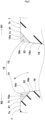
- FIG. 1 is a development of a tread portion 2 of a tire 1 according to the present embodiment (hereinafter, sometimes simply referred to as "tire").
- the tire 1 of the present embodiment is, for example, preferably a tire for a passenger car.
- the tire 1 of the present invention is not limited to thereto, and may be a heavy duty tire, for example.
- the tire 1 of the present invention includes a tread portion 2 having a designated rotation direction R.
- the rotation direction R is indicated, for example, on each sidewall portion (not shown) by characters or marks.
- the tread portion 2 of the tire 1 includes a first tread end T1 and a second tread end T2.
- first tread end T1 a tread end on the left side of a tire equator C
- second tread end T2 a tread end on the right side of the tire equator C
- the tread portion 2 includes a first tread portion 2A on the first tread end T1 side with respect to the tire equator C and a second tread portion 2B on the second tread end T2 side with respect to the tire equator C.
- the first tread portion 2A and the second tread portion 2B are substantially line-symmetric with respect to the tire equator C except that the first tread portion 2A and the second tread portion 2B are displaced in the tire circumferential direction. Accordingly, each configuration of the first tread portion 2A can be applied to the second tread portion 2B.
- the first tread end T1 and the second tread end T2 each indicate an outermost ground contact position in the tire axial direction in the case where 60% of a standardized load is applied to the tire 1 in a standardized state and the tire 1 is in contact with a flat plane at a camber angle of 0°.
- the "standardized state” represents a state in which a tire is fitted on a standardized rim and is inflated to a standardized internal pressure and no load is applied to the tire when the tire is a pneumatic tire for which various standards are defined.
- the standardized state represents a standard use state, corresponding to a purpose of use of the tire, in which no load is applied to the tire.
- the dimensions of the components of the tire and the like are represented by values measured in the standardized state.
- a known method can be used as a method for measuring the dimensions or compositions of material.
- the "standardized rim” represents a rim that is defined by a standard for each tire, in a standard system including the standard on which the tire is based, and is, for example, “standard rim” in the JATMA standard, "Design Rim” in the TRA standard, or “Measuring Rim” in the ETRTO standard.
- the "standardized internal pressure” represents an air pressure that is defined by a standard for each tire, in a standard system including the standard on which the tire is based, and is “maximum air pressure” in the JATMA standard, the maximum value recited in the table "TIRE LOAD LIMITS AT VARIOUS COLD INFLATION PRESSURES" in the TRA standard, or "INFLATION PRESSURE” in the ETRTO standard.
- the "standardized load” represents a load that is defined by a standard for each tire, in a standard system including the standard on which the tire is based, for pneumatic tires for which various standards are defined, and is "maximum load capacity" in the JATMA standard, the maximum value recited in the table "TIRE LOAD LIMITS AT VARIOUS COLD INFLATION PRESSURES" in the TRA standard, or "LOAD CAPACITY” in the ETRTO standard.
- the "standardized load” refers to the maximum load applicable when the tire is used, according to the above-described standards.
- the tread portion 2 includes a plurality of first inclined grooves 5.
- the first inclined grooves 5 extend at least from the first tread end T1 toward the tire equator C side so as to be inclined to a leading edge side (the lower side in each drawing of the present application) in the rotation direction R.
- the first inclined grooves 5 of the present embodiment terminate before reaching the tire equator C.
- the first inclined grooves 5 may each cross the tire equator C.
- the tread portion 2 includes a plurality of first land portions 7 demarcated by the first inclined grooves 5.
- the tread portion 2 of the present embodiment includes a plurality of second inclined grooves 6 and a plurality of second land portions 8.
- the second inclined grooves 6 extend at least from the second tread end T2 toward the tire equator C side so as to be inclined to the leading edge side.
- the second land portions 8 are demarcated by the second inclined grooves 6.
- the second inclined grooves 6 have substantially the same configurations as the first inclined grooves 5, and the configurations of the first inclined grooves 5 can be applied to the second inclined grooves 6.
- the second land portions 8 have substantially the same configurations as the first land portions 7, and the configurations of the first land portions 7 can be applied to the second land portions 8.
- Each of the first inclined grooves 5 and the second inclined grooves 6 has a groove width of, for example, 2 to 12 mm.
- each of the first inclined grooves 5 and the second inclined grooves 6 has the groove width reduced from the first tread end T1 side or the second tread end T2 side toward the tire equator C side.
- each of the first inclined grooves 5 and the second inclined grooves 6 has a depth of, for example, 5 to 15 mm.
- each dimension of the first inclined grooves 5 and the second inclined grooves 6 is not limited thereto.
- FIG. 2 is an enlarged view of two first inclined grooves 5 and one first land portion 7. As shown in FIG. 2 , an inner end 5i of each of the plurality of first inclined grooves 5 in the tire axial direction is located on the tire equator C side with respect to a first middle position 10.
- the first middle position 10 is a center position between the first tread end T1 and the tire equator C in the tread portion 2 in the tire axial direction.
- an angle ⁇ 2 relative to the tire circumferential direction at the inner end 5i is smaller than an angle ⁇ 1 relative to the tire circumferential direction at the first middle position 10.
- FIG. 3 is a cross-sectional view taken along a line A-A in FIG. 2 , as a diagram showing a cross-section of each first inclined groove 5.
- each of the plurality of first inclined grooves 5 includes a first groove wall 11 on a leading edge side R1 in the rotation direction R and a second groove wall 12 on a trailing edge side R2 in the rotation direction R.
- the second groove wall 12 includes a chamfered portion 15 in an inner region 5A on the inner end 5i side with respect to the first middle position 10.
- a chamfered portion 15 is also formed on the first groove wall 11.
- the chamfered portion 15 formed on the first groove wall 11 is sometimes referred to as first chamfered portion 13, and the chamfered portion 15 formed on the second groove wall 12 is sometimes referred to as second chamfered portion 14.
- first chamfered portion 13 the chamfered portion 15 formed on the first groove wall 11 is sometimes referred to as first chamfered portion 13
- second chamfered portion 14 the chamfered portion 15 formed on the second groove wall 12 is sometimes referred to as second chamfered portion 14.
- the chamfered portions 15 are omitted.
- the chamfered portions 15 are conceptually shown by dots for easy understanding.
- a chamfered area of the chamfered portion 15 provided at least in the second groove wall 12 increases toward the inner end 5i side.
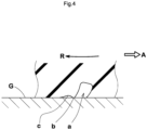
- FIG. 4 is an enlarged cross-sectional view showing a state when a conventional inclined groove a in which no chamfered portion is provided is in contact with the ground.
- FIG. 4 shows a state during braking, and an arrow R represents the rotation direction of the tire and an arrow A represents the traveling direction of the tire. As shown in FIG.
- the above-described issue is caused also during cornering. That is, when the groove such as the inner region 5A of the present invention is provided with no chamfered portion, an edge on the outer side of cornering of the land portion is drawn in under the tread surface of the land portion, for example, during sharp cornering, the land portion in the vicinity of the edge locally rises from the road surface, and thus grip cannot be sufficiently exhibited in some cases.
- at least the second groove wall 12 of the inner region 5A includes the chamfered portion 15 as shown in FIG. 2 and FIG. 3 , and the chamfered area of this chamfered portion 15 increases toward the inner end 5i side of the first inclined groove 5. Accordingly, the above-described issue is prevented, grip during cornering is enhanced, and excellent cornering performance can be exhibited.
- the groove provided with a chamfered portion has the increased groove volume, thereby impairing the noise performance in some cases.
- the chamfered area on the first middle position side is relatively small in the present invention.
- noise can be restrained from being increased due to the increased groove volume in the chamfered portion, and the noise performance can be maintained.
- the tire 1 of the present invention can improve the cornering performance while maintaining the noise performance.
- FIG. 5 shows an enlarged view of the first chamfered portion 13 and the second chamfered portion 14.
- the chamfered portions 15 each include a flat surface or a curved surface (hereinafter, both are sometimes collectively referred to as inclined surface) that is inclined so as to connect a main body 16a of the groove wall 16 and a tread surface 7s of the first land portion 7 such that a pointed corner portion is not formed by the groove wall 16 of the first inclined groove 5 and the tread surface 7s.
- each chamfered portion 15 is defined as described below. That is, the chamfered area refers to the area of a region surrounded by an inclined surface 15a of the chamfered portion 15, a virtual tread surface 7v obtained by extending the tread surface 7s of the first land portion 7 in the groove width direction of the first inclined groove 5, and a virtual groove wall 16v obtained by extending the main body 16a of the groove wall 16 of the first inclined groove 5 to the virtual tread surface 7v.
- the inclined surface 15a of each chamfered portion 15 refers to a surface from the main body 16a of the groove wall 16 to the tread surface 7s of the first land portion 7.
- the virtual tread surface 7v is a virtual surface obtained by extending the tread surface 7s from the boundary in the groove width direction. When the tread surface is curved, the virtual tread surface 7v corresponds to a curved line that extends from the boundary while maintaining the curvature of the tread surface 7s in a cross-section of the first inclined groove 5.
- the virtual groove wall 16v is a virtual surface obtained by extending the main body 16a from a boundary 22 between the main body 16a of the groove wall 16 and the inclined surface 15a to the virtual tread surface 7v.
- the boundary 22 between the main body 16a of the groove wall 16 and the inclined surface 15a is a position where an angle of the groove wall 16 relative to the tire radial direction is abruptly changed.
- the position is an area having a substantial width, the position closest to the groove center line corresponds to the boundary 22.
- an angle of each first inclined groove 5 relative to the tire circumferential direction preferably increases toward the outer side in the tire axial direction.
- each first inclined groove 5 extends so as to be curved.
- the angle ⁇ 2 of each first inclined groove 5 relative to the tire circumferential direction at the inner end 5i on the tire equator C side of the first inclined groove 5 is, for example, not less than 5°, and preferably 5 to 30°.
- the angle ⁇ 1 of each first inclined groove 5 relative to the tire circumferential direction at the first middle position 10 is, for example, not less than 30° and preferably 30 to 60°.
- An angle ⁇ 3 of each first inclined groove 5 relative to the tire circumferential direction at the first tread end T1 is preferably 80 to 90°. Accordingly, the braking performance and the cornering performance are also improved in a well-balanced manner.
- a distance L1 in the tire axial direction from the inner end 5i on the tire equator C side to the tire equator C is, for example, not greater than 10% of a tread width TW (shown in FIG. 1 ) and preferably not greater than 5% thereof.
- the tread width TW corresponds to a distance in the tire axial direction from the first tread end T1 to the second tread end T2 in the standardized state.
- the first inclined grooves 5 extend beyond the first tread end T1. Accordingly, excellent wet performance can be obtained.
- the second chamfered portion 14 is disposed on a part of each inner region 5A, the above-described effect can be expected to a certain degree.
- the second chamfered portion 14 is preferably provided in the inner region 5A in a range of not less than 50% of an entire length thereof and more preferably in the inner region 5A over the entire length thereof.
- the tread surfaces 7s of the first land portions 7, the groove walls 16 of the first inclined groove 5, and the inclined surfaces 15a of the chamfered portions 15 are each substantially formed planar, and formed linear in a cross-sectional view of the first inclined groove 5.
- the chamfered portion 15 is, for example, formed in an obtuse-angled triangular shape in a cross-sectional view.
- each second chamfered portion 14 continuously increases from the first middle position 10 to the inner end 5i. Accordingly, the cornering performance can be further improved.
- the chamfered area is not less than 0.5 mm 2 , and preferably 0.5 to 2.0 mm 2 . However, the chamfered area is not limited thereto.
- first chamfered portion 13 and the second chamfered portion 14 have substantially the same configurations.
- Each first land portion 7 is provided with neither grooves nor sipes in a range from the tire equator C to the first tread end T1, and is formed as a smooth tread surface. Such a first land portion 7 can exhibit excellent traction performance and braking performance.
- Each first land portion 7 is provided with a lateral narrow groove 25 extending in the tire axial direction, on the outer side of the first tread end T1 in the tire axial direction.
- a lateral narrow groove 25 serves to enhance wet performance and anti-wandering performance.
- the tread portion 2 of the present embodiment is provided with a plurality of lateral grooves 30 each extending from the first inclined groove 5 to the second inclined groove 6.
- the lateral grooves 30 include first lateral grooves 31 inclined relative to the tire axial direction and second lateral grooves 32 inclined, relative to the tire axial direction, in a direction opposite to that of the first lateral grooves 31.
- the first lateral grooves 31 and the second lateral grooves 32 are alternated in the tire circumferential direction.
- Such first lateral grooves 31 and second lateral grooves 32 serve to enhance wet performance.
Landscapes
- Engineering & Computer Science (AREA)
- Mechanical Engineering (AREA)
- Tires In General (AREA)
Claims (4)
- Reifen (1), umfassend einen Laufflächenabschnitt (2) mit einer bestimmten Drehrichtung (R), wobeider Laufflächenabschnitt (2) umfasst:ein erstes Laufflächenende (T1);eine erste Mittelposition (10), die eine Mittelposition zwischen dem ersten Laufflächenende (T1) und einem Reifenäquator (C) in einer Reifenaxialrichtung ist; undeine Vielzahl von ersten geneigten Rillen (5), die sich zumindest von dem ersten Laufflächenende (T1) zu dem Reifenäquator (C) erstrecken, so dass sie zu einer Vorderkantenseite in der Drehrichtung (R) geneigt sind,ein inneres Ende (5i) von jeder der Vielzahl von ersten geneigten Rillen (5) in der Reifenaxialrichtung auf der Seite des Reifenäquators (C) in Bezug auf die erste Mittelposition (10) angeordnet ist,in jeder der Vielzahl von ersten geneigten Rillen (5) ein Winkel (θ2) relativ zu einer Reifenumfangsrichtung an dem inneren Ende (5i) kleiner ist als ein Winkel (θ1) relativ zu der Reifenumfangsrichtung an der ersten Mittelposition (10),jede der Vielzahl von ersten geneigten Rillen (5) eine erste Rillenwand (11) auf der Vorderkantenseite in der Drehrichtung (R) und eine zweite Rillenwand (12) auf einer Hinterkantenseite in der Drehrichtung (R) umfasst,in einem inneren Bereich (5A) auf der Seite des inneren Endes (5i) in Bezug auf die erste Mittelposition (10) von jeder der Vielzahl von ersten geneigten Rillen (5) die zweite Rillenwand (12) einen abgeschrägten Abschnitt (15) umfasst, wobei der abgeschrägte Abschnitt (15) der zweiten Rillenwand (12) in dem inneren Bereich (5A) über eine gesamte Länge des inneren Bereichs (5A) vorgesehen ist,dadurch gekennzeichnet, dassin einem Querschnitt orthogonal zu einer Rillenmittellinie der ersten geneigten Rille (5) eine abgeschrägte Fläche des abgeschrägten Abschnitts (15) in Richtung der Seite des inneren Endes (5i) zunimmt, wobei die abgeschrägte Fläche des abgeschrägten Abschnitts (15) der zweiten Rillenwand (12) kontinuierlich von der ersten Mittelposition (10) zu dem inneren Ende (5i) zunimmt, undwobei die abgeschrägte Fläche gemäß der Beschreibung bestimmt wird.
- Reifen (1) nach Anspruch 1, wobei in einem äußeren Bereich (5B) auf der Seite des ersten Laufflächenendes (T1) in Bezug auf die erste Mittelposition (10) von jeder der Vielzahl von ersten geneigten Rillen (5) kein abgeschrägter Abschnitt auf der zweiten Rillenwand (12) ausgebildet ist.
- Reifen (1) nach Anspruch 1 oder 2, wobei ein Winkel jeder ersten geneigten Rille (5) relativ zu der Reifenumfangsrichtung kontinuierlich von dem inneren Ende (5i) zu dem ersten Laufflächenende (T1) zunimmt.
- Reifen (1) nach einem der Ansprüche 1 bis 3, wobei die abgeschrägte Fläche nicht weniger als 0,5 mm2 beträgt.
Applications Claiming Priority (1)
| Application Number | Priority Date | Filing Date | Title |
|---|---|---|---|
| JP2022039481A JP2023134122A (ja) | 2022-03-14 | 2022-03-14 | タイヤ |
Publications (2)
| Publication Number | Publication Date |
|---|---|
| EP4245572A1 EP4245572A1 (de) | 2023-09-20 |
| EP4245572B1 true EP4245572B1 (de) | 2025-04-16 |
Family
ID=85285022
Family Applications (1)
| Application Number | Title | Priority Date | Filing Date |
|---|---|---|---|
| EP23157461.7A Active EP4245572B1 (de) | 2022-03-14 | 2023-02-20 | Reifen |
Country Status (2)
| Country | Link |
|---|---|
| EP (1) | EP4245572B1 (de) |
| JP (1) | JP2023134122A (de) |
Family Cites Families (11)
| Publication number | Priority date | Publication date | Assignee | Title |
|---|---|---|---|---|
| JP4266402B2 (ja) * | 1997-03-26 | 2009-05-20 | 株式会社ブリヂストン | 方向性傾斜溝を備えた乗用車用空気入りラジアル・タイヤ |
| JP3924049B2 (ja) * | 1997-07-08 | 2007-06-06 | 株式会社ブリヂストン | オール・シーズン乗用車用空気入りラジアル・タイヤ |
| JP3678727B2 (ja) * | 2003-01-07 | 2005-08-03 | 住友ゴム工業株式会社 | 空気入りタイヤ |
| JP4996661B2 (ja) * | 2009-10-15 | 2012-08-08 | 住友ゴム工業株式会社 | 空気入りタイヤ |
| JP5452338B2 (ja) * | 2010-04-21 | 2014-03-26 | 住友ゴム工業株式会社 | 空気入りタイヤ |
| JP2016088407A (ja) * | 2014-11-10 | 2016-05-23 | 横浜ゴム株式会社 | 空気入りタイヤ |
| JP6364342B2 (ja) * | 2014-12-22 | 2018-07-25 | 東洋ゴム工業株式会社 | 空気入りタイヤ |
| JP7024512B2 (ja) | 2018-03-09 | 2022-02-24 | 住友ゴム工業株式会社 | タイヤ |
| CN114599530B (zh) * | 2019-11-06 | 2023-10-20 | 米其林集团总公司 | 包括胎面的轮胎 |
| WO2021089964A1 (fr) * | 2019-11-06 | 2021-05-14 | Compagnie Generale Des Etablissements Michelin | Pneumatique comportant une bande de roulement |
| FR3108561B1 (fr) * | 2020-03-26 | 2022-03-11 | Michelin & Cie | Pneumatique comportant une bande de roulement optimisée en adhérence sur sol sec |
-
2022
- 2022-03-14 JP JP2022039481A patent/JP2023134122A/ja active Pending
-
2023
- 2023-02-20 EP EP23157461.7A patent/EP4245572B1/de active Active
Also Published As
| Publication number | Publication date |
|---|---|
| EP4245572A1 (de) | 2023-09-20 |
| JP2023134122A (ja) | 2023-09-27 |
Similar Documents
| Publication | Publication Date | Title |
|---|---|---|
| EP3647077B1 (de) | Reifen | |
| EP3296127B1 (de) | Luftreifen | |
| EP4151434B1 (de) | Reifen | |
| EP3552847B1 (de) | Reifen | |
| EP4245571B1 (de) | Reifen | |
| EP4484179B1 (de) | Reifen | |
| EP3747672B1 (de) | Reifenlauffläche | |
| US12570107B2 (en) | Tire | |
| EP4245572B1 (de) | Reifen | |
| EP4151435B1 (de) | Reifen | |
| EP4151432B1 (de) | Reifen | |
| US11884108B2 (en) | Tire | |
| US12275278B2 (en) | Tire | |
| US12358325B2 (en) | Tire | |
| JP7669781B2 (ja) | タイヤ | |
| EP4105041B1 (de) | Reifen | |
| EP4556259A1 (de) | Reifen | |
| EP4105044B1 (de) | Reifen | |
| EP4417441A1 (de) | Reifen | |
| CN111038180B (zh) | 轮胎 |
Legal Events
| Date | Code | Title | Description |
|---|---|---|---|
| PUAI | Public reference made under article 153(3) epc to a published international application that has entered the european phase |
Free format text: ORIGINAL CODE: 0009012 |
|
| STAA | Information on the status of an ep patent application or granted ep patent |
Free format text: STATUS: THE APPLICATION HAS BEEN PUBLISHED |
|
| AK | Designated contracting states |
Kind code of ref document: A1 Designated state(s): AL AT BE BG CH CY CZ DE DK EE ES FI FR GB GR HR HU IE IS IT LI LT LU LV MC ME MK MT NL NO PL PT RO RS SE SI SK SM TR |
|
| STAA | Information on the status of an ep patent application or granted ep patent |
Free format text: STATUS: REQUEST FOR EXAMINATION WAS MADE |
|
| 17P | Request for examination filed |
Effective date: 20240216 |
|
| RBV | Designated contracting states (corrected) |
Designated state(s): AL AT BE BG CH CY CZ DE DK EE ES FI FR GB GR HR HU IE IS IT LI LT LU LV MC ME MK MT NL NO PL PT RO RS SE SI SK SM TR |
|
| P01 | Opt-out of the competence of the unified patent court (upc) registered |
Effective date: 20240327 |
|
| GRAP | Despatch of communication of intention to grant a patent |
Free format text: ORIGINAL CODE: EPIDOSNIGR1 |
|
| STAA | Information on the status of an ep patent application or granted ep patent |
Free format text: STATUS: GRANT OF PATENT IS INTENDED |
|
| INTG | Intention to grant announced |
Effective date: 20250124 |
|
| GRAS | Grant fee paid |
Free format text: ORIGINAL CODE: EPIDOSNIGR3 |
|
| GRAA | (expected) grant |
Free format text: ORIGINAL CODE: 0009210 |
|
| STAA | Information on the status of an ep patent application or granted ep patent |
Free format text: STATUS: THE PATENT HAS BEEN GRANTED |
|
| AK | Designated contracting states |
Kind code of ref document: B1 Designated state(s): AL AT BE BG CH CY CZ DE DK EE ES FI FR GB GR HR HU IE IS IT LI LT LU LV MC ME MK MT NL NO PL PT RO RS SE SI SK SM TR |
|
| REG | Reference to a national code |
Ref country code: GB Ref legal event code: FG4D |
|
| REG | Reference to a national code |
Ref country code: CH Ref legal event code: EP Ref country code: DE Ref legal event code: R096 Ref document number: 602023002876 Country of ref document: DE |
|
| REG | Reference to a national code |
Ref country code: IE Ref legal event code: FG4D |
|
| REG | Reference to a national code |
Ref country code: NL Ref legal event code: MP Effective date: 20250416 |
|
| PG25 | Lapsed in a contracting state [announced via postgrant information from national office to epo] |
Ref country code: NL Free format text: LAPSE BECAUSE OF FAILURE TO SUBMIT A TRANSLATION OF THE DESCRIPTION OR TO PAY THE FEE WITHIN THE PRESCRIBED TIME-LIMIT Effective date: 20250416 |
|
| REG | Reference to a national code |
Ref country code: AT Ref legal event code: MK05 Ref document number: 1785363 Country of ref document: AT Kind code of ref document: T Effective date: 20250416 |
|
| PG25 | Lapsed in a contracting state [announced via postgrant information from national office to epo] |
Ref country code: FI Free format text: LAPSE BECAUSE OF FAILURE TO SUBMIT A TRANSLATION OF THE DESCRIPTION OR TO PAY THE FEE WITHIN THE PRESCRIBED TIME-LIMIT Effective date: 20250416 Ref country code: PT Free format text: LAPSE BECAUSE OF FAILURE TO SUBMIT A TRANSLATION OF THE DESCRIPTION OR TO PAY THE FEE WITHIN THE PRESCRIBED TIME-LIMIT Effective date: 20250818 Ref country code: ES Free format text: LAPSE BECAUSE OF FAILURE TO SUBMIT A TRANSLATION OF THE DESCRIPTION OR TO PAY THE FEE WITHIN THE PRESCRIBED TIME-LIMIT Effective date: 20250416 |
|
| REG | Reference to a national code |
Ref country code: LT Ref legal event code: MG9D |
|
| PG25 | Lapsed in a contracting state [announced via postgrant information from national office to epo] |
Ref country code: GR Free format text: LAPSE BECAUSE OF FAILURE TO SUBMIT A TRANSLATION OF THE DESCRIPTION OR TO PAY THE FEE WITHIN THE PRESCRIBED TIME-LIMIT Effective date: 20250717 Ref country code: NO Free format text: LAPSE BECAUSE OF FAILURE TO SUBMIT A TRANSLATION OF THE DESCRIPTION OR TO PAY THE FEE WITHIN THE PRESCRIBED TIME-LIMIT Effective date: 20250716 |
|
| PG25 | Lapsed in a contracting state [announced via postgrant information from national office to epo] |
Ref country code: PL Free format text: LAPSE BECAUSE OF FAILURE TO SUBMIT A TRANSLATION OF THE DESCRIPTION OR TO PAY THE FEE WITHIN THE PRESCRIBED TIME-LIMIT Effective date: 20250416 |
|
| PG25 | Lapsed in a contracting state [announced via postgrant information from national office to epo] |
Ref country code: BG Free format text: LAPSE BECAUSE OF FAILURE TO SUBMIT A TRANSLATION OF THE DESCRIPTION OR TO PAY THE FEE WITHIN THE PRESCRIBED TIME-LIMIT Effective date: 20250416 |
|
| PG25 | Lapsed in a contracting state [announced via postgrant information from national office to epo] |
Ref country code: HR Free format text: LAPSE BECAUSE OF FAILURE TO SUBMIT A TRANSLATION OF THE DESCRIPTION OR TO PAY THE FEE WITHIN THE PRESCRIBED TIME-LIMIT Effective date: 20250416 |
|
| PG25 | Lapsed in a contracting state [announced via postgrant information from national office to epo] |
Ref country code: AT Free format text: LAPSE BECAUSE OF FAILURE TO SUBMIT A TRANSLATION OF THE DESCRIPTION OR TO PAY THE FEE WITHIN THE PRESCRIBED TIME-LIMIT Effective date: 20250416 |
|
| PG25 | Lapsed in a contracting state [announced via postgrant information from national office to epo] |
Ref country code: RS Free format text: LAPSE BECAUSE OF FAILURE TO SUBMIT A TRANSLATION OF THE DESCRIPTION OR TO PAY THE FEE WITHIN THE PRESCRIBED TIME-LIMIT Effective date: 20250716 |
|
| PG25 | Lapsed in a contracting state [announced via postgrant information from national office to epo] |
Ref country code: IS Free format text: LAPSE BECAUSE OF FAILURE TO SUBMIT A TRANSLATION OF THE DESCRIPTION OR TO PAY THE FEE WITHIN THE PRESCRIBED TIME-LIMIT Effective date: 20250816 |
|
| PG25 | Lapsed in a contracting state [announced via postgrant information from national office to epo] |
Ref country code: LV Free format text: LAPSE BECAUSE OF FAILURE TO SUBMIT A TRANSLATION OF THE DESCRIPTION OR TO PAY THE FEE WITHIN THE PRESCRIBED TIME-LIMIT Effective date: 20250416 |
|
| PG25 | Lapsed in a contracting state [announced via postgrant information from national office to epo] |
Ref country code: DK Free format text: LAPSE BECAUSE OF FAILURE TO SUBMIT A TRANSLATION OF THE DESCRIPTION OR TO PAY THE FEE WITHIN THE PRESCRIBED TIME-LIMIT Effective date: 20250416 Ref country code: SM Free format text: LAPSE BECAUSE OF FAILURE TO SUBMIT A TRANSLATION OF THE DESCRIPTION OR TO PAY THE FEE WITHIN THE PRESCRIBED TIME-LIMIT Effective date: 20250416 |
|
| PGFP | Annual fee paid to national office [announced via postgrant information from national office to epo] |
Ref country code: FR Payment date: 20251231 Year of fee payment: 4 |
|
| REG | Reference to a national code |
Ref country code: DE Ref legal event code: R097 Ref document number: 602023002876 Country of ref document: DE |
|
| PG25 | Lapsed in a contracting state [announced via postgrant information from national office to epo] |
Ref country code: CZ Free format text: LAPSE BECAUSE OF FAILURE TO SUBMIT A TRANSLATION OF THE DESCRIPTION OR TO PAY THE FEE WITHIN THE PRESCRIBED TIME-LIMIT Effective date: 20250416 |
|
| PG25 | Lapsed in a contracting state [announced via postgrant information from national office to epo] |
Ref country code: EE Free format text: LAPSE BECAUSE OF FAILURE TO SUBMIT A TRANSLATION OF THE DESCRIPTION OR TO PAY THE FEE WITHIN THE PRESCRIBED TIME-LIMIT Effective date: 20250416 |
|
| PG25 | Lapsed in a contracting state [announced via postgrant information from national office to epo] |
Ref country code: SK Free format text: LAPSE BECAUSE OF FAILURE TO SUBMIT A TRANSLATION OF THE DESCRIPTION OR TO PAY THE FEE WITHIN THE PRESCRIBED TIME-LIMIT Effective date: 20250416 |
|
| PG25 | Lapsed in a contracting state [announced via postgrant information from national office to epo] |
Ref country code: IT Free format text: LAPSE BECAUSE OF FAILURE TO SUBMIT A TRANSLATION OF THE DESCRIPTION OR TO PAY THE FEE WITHIN THE PRESCRIBED TIME-LIMIT Effective date: 20250416 |
|
| PLBE | No opposition filed within time limit |
Free format text: ORIGINAL CODE: 0009261 |
|
| STAA | Information on the status of an ep patent application or granted ep patent |
Free format text: STATUS: NO OPPOSITION FILED WITHIN TIME LIMIT |
|
| REG | Reference to a national code |
Ref country code: CH Ref legal event code: L10 Free format text: ST27 STATUS EVENT CODE: U-0-0-L10-L00 (AS PROVIDED BY THE NATIONAL OFFICE) Effective date: 20260225 |
|
| 26N | No opposition filed |
Effective date: 20260119 |
|
| PGFP | Annual fee paid to national office [announced via postgrant information from national office to epo] |
Ref country code: DE Payment date: 20251230 Year of fee payment: 4 |