EP4245200B1 - Wiederverwendbarer fixierter tissue-halter - Google Patents
Wiederverwendbarer fixierter tissue-halter Download PDFInfo
- Publication number
- EP4245200B1 EP4245200B1 EP22166439.4A EP22166439A EP4245200B1 EP 4245200 B1 EP4245200 B1 EP 4245200B1 EP 22166439 A EP22166439 A EP 22166439A EP 4245200 B1 EP4245200 B1 EP 4245200B1
- Authority
- EP
- European Patent Office
- Prior art keywords
- bar frame
- channel
- bar
- tissue holder
- suction cup
- Prior art date
- Legal status (The legal status is an assumption and is not a legal conclusion. Google has not performed a legal analysis and makes no representation as to the accuracy of the status listed.)
- Active
Links
Images




Classifications
-
- A—HUMAN NECESSITIES
- A47—FURNITURE; DOMESTIC ARTICLES OR APPLIANCES; COFFEE MILLS; SPICE MILLS; SUCTION CLEANERS IN GENERAL
- A47K—SANITARY EQUIPMENT; ACCESSORIES THEREFOR, e.g. TOILET ACCESSORIES
- A47K10/00—Body-drying implements; Toilet paper; Holders therefor
- A47K10/24—Towel dispensers; Toilet paper dispensers
- A47K10/32—Dispensers for paper towels or toilet paper
- A47K10/34—Dispensers for paper towels or toilet paper dispensing from a web, e.g. with mechanical dispensing means
- A47K10/38—Dispensers for paper towels or toilet paper dispensing from a web, e.g. with mechanical dispensing means the web being rolled-up
- A47K10/3836—Dispensers for paper towels or toilet paper dispensing from a web, e.g. with mechanical dispensing means the web being rolled-up with roll spindles which are supported at one side
-
- A—HUMAN NECESSITIES
- A47—FURNITURE; DOMESTIC ARTICLES OR APPLIANCES; COFFEE MILLS; SPICE MILLS; SUCTION CLEANERS IN GENERAL
- A47K—SANITARY EQUIPMENT; ACCESSORIES THEREFOR, e.g. TOILET ACCESSORIES
- A47K10/00—Body-drying implements; Toilet paper; Holders therefor
- A47K10/16—Paper towels; Toilet paper; Holders therefor
- A47K10/18—Holders; Receptacles
- A47K10/22—Holders; Receptacles for rolled-up webs
-
- A—HUMAN NECESSITIES
- A47—FURNITURE; DOMESTIC ARTICLES OR APPLIANCES; COFFEE MILLS; SPICE MILLS; SUCTION CLEANERS IN GENERAL
- A47K—SANITARY EQUIPMENT; ACCESSORIES THEREFOR, e.g. TOILET ACCESSORIES
- A47K10/00—Body-drying implements; Toilet paper; Holders therefor
- A47K10/24—Towel dispensers; Toilet paper dispensers
- A47K10/32—Dispensers for paper towels or toilet paper
- A47K10/34—Dispensers for paper towels or toilet paper dispensing from a web, e.g. with mechanical dispensing means
- A47K10/38—Dispensers for paper towels or toilet paper dispensing from a web, e.g. with mechanical dispensing means the web being rolled-up
- A47K2010/3863—Dispensers for paper towels or toilet paper dispensing from a web, e.g. with mechanical dispensing means the web being rolled-up with roll rotation braking devices
Definitions
- the present invention relates to the technical field of furniture items, in particular to a reusable fixed tissue holder.
- a toilet roll and a tissue are common items in our life.
- a tissue holder formed by making a housing of plastic or metal material, disposing a shaft on a base, sleeving the shaft with a middle circular hole of a tissue roll and internally placing or laying a container for placing toilet roll or folding paper is used on private or public occasions such as homes, hotels, bathrooms, toilets, public places and entertainment venues.
- the tissue holder is generally fixed by bolt locking or double-sided adhesive tape attachment and is then sleeved by the toilet roll, and the next section of toilet roll needs to be torn down when being used.
- a multipurpose tissue holder disclosed in a patent with the patent No. CN200920002764.9 a tissue holder with a suction cup disclosed in a patent with the patent No. CN201922455866.2 , a tissue holder capable of more stably holding tissues disclosed in a patent with the patent No. CN202010878374.9 and a suction-cup-type tissue holder disclosed in a patent with the patent No. CN201120532318.6 are all attached on a mounting wall surface by using a suction cup, so that it is possible that the tissue holder is mounted on other places after being dismounted.
- the suction cup due to characteristics of the suction cup, the suction cup needs to be vigorously squeezed to be attached on a smooth wall surface when being used, however, the tissue holder cannot be better fixed except that a gas between the suction cup and the wall surface is exhausted to form a negative pressure during pressurization.
- the tissue holder requires higher adsorption capacity, generally, the suction cup cannot be undersized, or else, the tissue holder cannot be effectively borne.
- Document GB2433490A is background art which is regarded as useful to understand the invention. It discloses a holder for a roll of paper.
- the purpose of the present invention is to provide a reusable fixed tissue holder for solving the problem proposed in the above-mentioned background art.
- the present invention provides the following technical solution:
- tissue holder comprising a structure for exhausting a gas between the suction cup and a smooth surface when the suction cup is sucked or attached onto the smooth surface.
- the structure comprises an open pipe barrel and a rubber plug matched with the pipe barrel; the pipe barrel is connected with the second channel by a pipeline on which a one-way valve is disposed; and by pressing the second bar frame, the pipe barrel generates a negative pressure between the suction cup and the smooth surface by the second channel.
- the inside of the first bar frame is hollow, the second bar frame is movably inserted to the first bar frame; the pipe barrel is mounted in the first bar frame; and the second bar frame makes the pipe barrel generate a negative pressure by a linkage mechanism.
- the linkage mechanism comprises a first rack, a second rack and a gear; one end of the first rack is connected with the bottom end of the second bar frame, and the other end of the first rack is engaged with the gear mounted in the first bar frame; and one end of the second rack is engaged with the gear, and the other end of the second rack is connected with the rubber plug.
- a sliding chute is formed in the inner wall of the first bar frame; a sliding block of the second bar frame is slidably connected with the sliding chute; a supporting bar is mounted on the second rack located outside the pipe barrel; the sliding block of the supporting bar is slidably connected with the sliding chute; an exhaust hole is reserved in the bottom of the pipe barrel; and one end of a plug lid passes through the first bar frame to plug up the exhaust hole.
- a push bar is connected to the bottom end of the second bar frame; the bottom end of the push bar is connected with the top end of the pipe barrel; the inside of the first bar frame is hollow; the pipe barrel is mounted in the first bar frame; and one end of a fulcrum bar with a channel is connected with the rubber plug, and the other end of the fulcrum bar is fixed to the inner wall of the first bar frame.
- through holes connected with the channel are formed in upper and lower ends of the fulcrum bar, the through hole formed in the upper end is located in the pipe barrel, and the through hole formed in the lower end is connected with the pipeline ; an exhaust hole connected with the channel is reserved in the bottom of the fulcrum bar; and one end of the plug lid passes through the first bar frame to plug up the exhaust hole.
- the button structure comprises a button mounted on the side end surface of the base; an elastic element is disposed between the button and the base; the disc seat is connected with a connecting part mounted in the base and the connecting part is provided with a through groove which is provided with a groove opening; the button is equipped with a convex pressing block of which the diameter is slightly smaller than the internal diameter of the through groove, that is, air can enter the first channel through the groove opening; and the pressing block is located in the through groove and is used for plugging up the groove opening at the initial time.
- the button structure comprises a button mounted on the upper end surface of the base; the disc seat is connected with a connecting part mounted in the base, and the connecting part is provided with a through groove; the button is provided with a strip-shaped pressing block passing through the base and the connecting part; the pressing block located in the through groove is equipped with an elastic element; the pressing block is provided with a rectangular or [-shaped channel; an anti-drop block is disposed on the bottom of the pressing block; and an opening in the upper end of the rectangular channel is connected with the atmosphere at the initial time, and an opening at the lower end of the rectangular channel is sealed together with the inner wall of the connecting part so that the through groove is not connected with the atmosphere.
- a cavity is disposed between the top of the suction cup and the disc seat, the first channel and the second channel are connected with the cavity, the disc seat is provided with a convex sealing ring, and a ring groove adapted to the convex sealing ring is formed in the suction cup.
- the present invention has the following beneficial effects.
- the cavity is exhausted by using the pipe barrel to form a negative pressure, then, a negative pressure can be rapidly achieved between the suction cup and a wall surface to be attached and fixed thereto, and thus, the tissue holder can be attached on the wall surface without applying a great pressing force.
- the active negative pressure not only can the suction cup be rapidly attached, but also the purposes of adsorption and fixation can be achieved by the least pressing number of times.
- the air in a region between the suction cup and the wall surface can be evacuated as much as possible to form vacuum, so that the adsorption capacity is high, the adsorption and fixation effects are better, and both time and effort are saved when the suction cup is attached and fixed.
- the reusable fixed tissue holder the problem that the tissue holder is easily upset and cannot be repeatedly fixed or used is solved. The purpose that the tissue holder is easily fixed, is then easily unfixed and is fixed on other places so as to be reused is achieved.
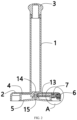
- the reusable fixed tissue holder further includes a structure for exhausting a gas between the suction cup 5 and a smooth surface when the suction cup 5 is sucked or attached onto the smooth surface.
- the button structure includes a button 6 mounted on the side end surface of the base 2; an elastic element 8 is disposed between the button 6 and the base 2; the disc seat 4 is connected with a connecting part 7 mounted in the base 2, and the connecting part 7 is provided with a through groove 12 which is provided with a groove opening 11; the button 6 is equipped with a convex pressing block 10 of which the diameter is slightly smaller than the internal diameter of the through groove 12, that is, air can enter the first channel 13 through the groove opening 11; and the pressing block 10 is located in the through groove 12 and is used for plugging up the groove opening 11 at the initial time.
- a cavity 14 is disposed between the top of the suction cup 5 and the disc seat 4, the first channel 13 and the second channel 15 are connected with the cavity 14, the disc seat 4 is provided with a convex sealing ring 28, and a ring groove 27 adapted to the convex sealing ring 28 is formed in the suction cup 5,
- the second bar frame 3 is pressed so that the suction cup 5 mounted on the bottom of the disc seat 4 can be attached on the smooth surface such as a wall surface.
- the convex pressing block 10 on the button 6 may plug up the groove opening 11 under the action of the elastic element 8, so that the through groove 12 may not be connected with the atmosphere.
- the second channel 15 of the suction cup 5 is prevented from being connected with the through groove 12. It can be ensured that the negative pressure between the suction cup and the wall surface is in a good state after the tissue holder is fixed to the smooth wall surface, so that the overall tissue holder can be very firm and cannot be easily upset when the suction cup is sucked.
- the button 6 of the base 2 is pressed down to cause the second channel 15 to be connected with the atmosphere after passing through the first channel 13 and the through groove 12, in this way, the suction cup 5 loses a suction force, the overall tissue holder may easily move, when the tissue holder is placed on a target place again, the button 6 is pressed down again, and thus, the suction cup 5 can be firmly fixed again.
- the convex sealing ring 28 may be tightly attached to the ring groove 27 after the suction cup 5 and the disc seat 4 are mounted, so that the sealing property of the suction cup 5 (the second channel 15) and the atmosphere (the first channel 13) can be improved.
- the button 6 when being released, the button 6 is turned off to block the flow of air, so that the suction cup 5 is fixed; and when being pressed down, the button 6 is turned on to achieve the flow of the air, so that the suction cup 5 is unlocked.
- the button 6 controls the first channel 13 to be connected with the bottom of the suction cup 5 (the second channel 15), and thus, if the button is turned on, the flow of the air is achieved, and the suction cup 5 is unlocked. That is, if the button is turned on, the flow of the air is achieved, and the suction cup 5 is rapidly unlocked.
- the size of the overall tissue holder, sizes of the parts and the like can be set according to actual use conditions.
- the internal diameter of the first channel 13 and the internal diameter of the second channel 15 can be set according to adsorption capacity.
- the elastic element 8 may adopt a reset spring
- the bar frame may be made of stainless steel or PVC
- the convex sealing ring 28 may be made of the same material as the suction cup 5, they can be flexibly selected according to specific conditions, the descriptions thereof are omitted herein.
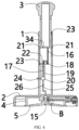
- the structure in the present embodiment is basically same as the structure in the embodiment 1, except that: the structure includes an open pipe barrel 19 and a rubber plug 20 matched with the pipe barrel 19; the pipe barrel 19 is connected with the second channel 15 by a pipeline 25 on which a one-way valve 26 is disposed; and by pressing the second bar frame 3, the pipe barrel 19 generates a negative pressure between the suction cup 5 and the smooth surface by the second channel 15.
- the inside of the first bar frame 1 is hollow; the second bar frame 3 is movably inserted to the first bar frame 1; the pipe barrel 19 is mounted in the first bar frame 1; and the second bar frame 3 makes the pipe barrel 19 generate a negative pressure by a linkage mechanism.
- the linkage mechanism includes a first rack 16, a second rack 17 and a gear 18; one end of the first rack 16 is connected with the bottom end of the second bar frame 3, and the other end of the first rack 16 is engaged with the gear 18 mounted in the first bar frame 1; and one end of the second rack 17 is engaged with the gear 18, and the other end of the second rack 17 is connected with the rubber plug 20.
- a sliding chute 21 is formed in the inner wall of the first bar frame 1, a sliding block 23 of the second bar frame 3 is slidably connected with the sliding chute 21; a supporting bar 22 is mounted on the second rack 17 located outside the pipe barrel 19; the sliding block 23 of the supporting bar 22 is slidably connected with the sliding chute 21; an exhaust hole (unshown in the figure) is reserved in the bottom of the pipe barrel 19; and one end of a plug lid 24 passes through the first bar frame 1 to plug up the exhaust hole.
- the purpose of rapidly unlocking the suction cup 5 in the above-mentioned embodiment 1 can be achieved.
- the tissue holder may be pressed on a wall body, so that the effort is saved, and adsorption and fixation to the smooth wall surface can be more rapidly achieved without pressing for an overlarge number of times within the same time, that is, the fixation efficiency of the suction cup 5 is higher.
- the first bar frame 1 and the second bar frame 3 are set to relatively slide, that is, the second bar frame 3 may slide along the first bar frame 1 by pressing the head of the second bar frame 3 during pressing.
- the head of the second bar frame 3 is pressed, in this way, the bottom end of the second bar frame 3 drives the first rack 16 to make the gear 18 rotate, the gear 18 is engaged with the second rack 17, then, the rubber plug 20 is uplifted by the second rack 17, the cavity 14 is exhausted by the pipe barrel 19 to form a negative pressure, and then, a negative pressure can be rapidly achieved between the suction cup 5 and a wall surface to be attached and fixed thereto, and thus, the tissue holder can be attached on the wall surface without applying a great pressing force.
- the suction cup 5 by using the active negative pressure, not only can the suction cup 5 be rapidly attached, but also the purposes of adsorption and fixation can be achieved by the least pressing number of times. Meanwhile, the air in a region between the suction cup and the wall surface can be evacuated as much as possible to form vacuum, so that the adsorption capacity is high, the adsorption and fixation effects are better, and as a whole, both time and effort are saved during adsorption and fixation.
- the purpose of attaching the suction cup 5 is achieved by the negative pressure generated by the linkage mechanism, and thus, the effects of attaching and fixing the tissue holder on the wall surface cannot be limited by a different size of the suction cup 5.
- the sliding chute 21 is formed in the inner wall of the first bar frame 1, and then, the corresponding sliding block 23 is slidably matched with the sliding chute 21, so that the above-mentioned stability is achieved.
- the button 6 is only pressed. Then, the plug lid 24 is pulled out, then, the second bar frame 3 is upwards pulled relative to the first bar frame 1, and thus, reset is achieved. After reset, the plug lid 24 is plugged again.
- An insertion hole 34 allowing the top end of the second rack 17 to be inserted is formed in the bottom of the second bar frame 3, so that the first rack 16, the gear 18, the second rack 17 and the like may be normally linked when being pressed by the second bar frame 3.
- the structure in the present embodiment is basically same as the structure in the embodiment 2, except that: a push bar 31 is connected to the bottom end of the second bar frame 3; the bottom end of the push bar 31 is connected with the top end of the pipe barrel 19; the inside of the first bar frame 1 is hollow; the pipe barrel 19 is mounted in the first bar frame 1; and one end of a fulcrum bar 29 with a channel 32 is connected with the rubber plug 20, and the other end of the fulcrum bar 29 is fixed to the inner wall of the first bar frame 1.
- through holes 30 connected with the channel 32 are formed in upper and lower ends of the fulcrum bar 29, the through hole 30 formed in the upper end is located in the pipe barrel 9, and the through hole 30 formed in the lower end is connected with the pipeline 25; an exhaust hole connected with the channel 32 is reserved in the bottom of the fulcrum bar 29; and one end of the plug lid 24 passes through the first bar frame 1 to plug up the exhaust hole.
- the opening of the pipe barrel 19 is downward and is opposite to the opening of the pipe barrel 19 in the embodiment 2.
- the pipe barrel 19 may move together with the second bar frame 3 relative to the first bar frame 1, and the fulcrum bar 29 and the rubber plug 20 are fixed relative to the first bar frame 1.
- the head of the second bar frame 3 is pressed, in this way, the bottom end of the second bar frame 3 drives the push bar 31 to drive the pipe barrel 19 to move downwards, then, air exhaust is achieved, a negative pressure is formed in the cavity 14, and thus, time-saving and effort-saving fixation of the suction cup 5 on the wall surface to be attached and fixed can be achieved as that in the above-mentioned embodiment 2.
- the structure is further simplified as comparison with that in the embodiment 2.
- the plug lid 24 is sealed with the exhaust hole of the inner channel 32 of the fulcrum bar 29, and therefore, when the suction cup is dismounted, as mentioned in the above-mentioned embodiment 1, the button 6 only needs to be pressed. Then, the plug lid 24 is pulled out, then, the second bar frame 3 is upwards pulled relative to the first bar frame 1, and thus, reset is achieved. After reset, the plug lid 24 is plugged again.
- the movement distance of the second bar frame 3 may be flexibly set according to a required condition, that is, in the embodiment 2, the second bar frame 3 moves downwards, which may not cause interference to the gear 18 and the second rack 17.
- the movement of the supporting bar 22 may not cause interference to the pipe barrel 19.
- the second bar frame 3 moves downwards to drive the pipe barrel 19 to move downwards, which may not cause interference to the plug lid 24, and the rubber plug 20 may not be separated from the opening of the pipe barrel 19 to the outside of the pipe barrel 19, the descriptions thereof are omitted herein.
- the structure in the present embodiment is basically same as the structure in the embodiment 1, except that: the button structure includes a button 6 mounted on the upper end surface of the base 2; the disc seat 4 is connected with a connecting part 7 mounted in the base 2, and the connecting part 7 is provided with a through groove 12; the button 6 is provided with a strip-shaped pressing block 10 passing through the base 2 and the connecting part 7; the pressing block 10 located in the through groove 12 is equipped with an elastic element 8; the pressing block 10 is provided with a rectangular or [-shaped channel 33; an anti-drop block 9 is disposed on the bottom of the pressing block 10; and an opening in the upper end of the rectangular channel 33 is connected with the atmosphere at the initial time, and an opening at the lower end of the rectangular channel 33 is sealed together with the inner wall of the connecting part 7 so that the through groove 12 is not connected with the atmosphere.
- the mounting position of the button structure is changed from the side end surface of the base 2 in the embodiment 1 to the upper end surface of the base 2.
- the purpose of such setting is that in combination with the embodiment 2 and the embodiment 3, the button structure is mounted on the side end surface of the base 2, the tissue holder may be pressed on the wall surface by using the linkage mechanism, so that the effort is saved, and the suction cup 5 may be attached and fixed to the wall surface to be mounted without pressing for an overlarge number of times.
- the linkage mechanism works, in this process, a negative pressure is formed in the cavity 14; however, after the negative pressure is formed in the cavity 14, the first channel 13 is connected with the through groove 12, and therefore, a force needs to be applied to the elastic element 8 in the negative pressure formation process.
- the elastic element 8 in order to keep a state that the groove opening 11 of the through groove 12 is plugged up by the pressing block 10, it is necessary to select the elastic element 8 with a reasonable elastic coefficient to resist to an acting force generated by the negative pressure, which may cause a larger elastic coefficient of the elastic element 8, thereby being not beneficial to the pressing of the button 6. Therefore, the mounting position of a mechanism such as the button 6 is changed to the upper end surface of the base 2, in this way, the problem can be avoided.
- the pressing block 10 moves downwards only when the button 6 is pressed again, which causes the opening in the upper end of the rectangular channel 33 therein to be located outside the inner wall of the connecting part 7 and the opening in the lower end of the rectangular channel 33 to be located in the inner wall of the connecting part 7, and thus, the purpose of connecting the through groove 12 to the atmosphere can be achieved through the rectangular channel 33.
- the through groove 12 can be isolated again from the atmosphere by the elastic element 8 sleeving the pressing block 10 in the through groove 12, so that the tissue holder can be used after being dismounted next time.
Landscapes
- Health & Medical Sciences (AREA)
- Public Health (AREA)
- Sampling And Sample Adjustment (AREA)
- Hooks, Suction Cups, And Attachment By Adhesive Means (AREA)
Claims (11)
- Wiederverwendbarer fixierter Tissuehalter, umfassendeinen Stangenrahmen, der einen ersten Stangenrahmen (1) und einen zweiten Stangenrahmen (3) umfasst,wobei der zweite Stangenrahmen den ersten Stangenrahmen (1) ummantelt;einem Sockel (2), der an einem Ende des ersten Stangenrahmens (I) befestigt ist;einem im Sockel (2) montierten Scheibensitz (4);einem Saugnapf (5), der auf dem Scheibensitz (4) angebracht ist,dadurch gekennzeichnet, dassein erster Kanal (13) auf dem Scheibensitz (4) angeordnet ist, und ein zweiter Kanal (15), der mit dem Kanal (13) verbunden ist, auf dem Saugnapf (5) angeordnet ist; unddass eine auf dem Sockel (2) montierte Knopfstruktur, die dazu dient, den ersten Kanal (13) und den zweiten Kanal (15) mit der Atmosphäre zu verbinden.
- Tissuehalter nach Anspruch 1, wobei er ferner eine Struktur umfasst, die dazu dient, ein Gas zwischen dem Saugnapf (5) und einer glatten Oberfläche zu absaugen, wenn der Saugnapf (5) an der glatten Oberfläche angebracht ist.
- Tissuehalter nach Anspruch 2, wobei die Struktur eine offene Rohrtrommel (19) und einen Gummistopfen (20) umfasst, der an die Rohrtrommel (19) angepasst ist; wobei die Rohrtrommel (19) mit dem zweiten Kanal (15) durch eine Rohrleitung (25) verbunden ist, an der ein Einwegventil (26) angeordnet ist; und wobei die Rohrtrommel (19) durch Drücken des zweiten Stangenrahmens (3) einen Unterdruck zwischen dem Saugnapf (5) und der glatten Oberfläche durch den zweiten Kanal (15) erzeugt.
- Tissuehalter nach Anspruch 3, wobei die Innenseite des ersten Stangenrahmens (1) hohl ist; wobei der zweite Stangenrahmen (3) beweglich in den ersten Stangenrahmen (1) eingesetzt ist, wobei die Rohrtrommel (19) in dem ersten Stangenrahmen (1) montiert ist; und wobei der zweite Stangenrahmen (3) bewirkt, dass die Rohrtrommel (19) durch einen Verbindungsmechanismus einen Unterdruck erzeugt.
- Tissuehalter nach Anspruch 4, wobei der Verbindungsmechanismus eine erste Zahnstange (16), eine zweite Zahnstange (17) und ein Zahnrad (18) umfasst; wobei ein Ende der ersten Zahnstange (16) mit dem unteren Ende des zweiten Stangenrahmens (3) verbunden ist und das andere Ende der ersten Zahnstange (16) mit dem im ersten Stangenrahmen (1) montierten Zahnrad (18) in Eingriff steht; und wobei ein Ende der zweiten Zahnstange (17) mit dem Zahnrad (18) in Eingriff steht und das andere Ende der zweiten Zahnstange (17) mit dem Gummistopfen (20) verbunden ist.
- Tissuehalter nach Anspruch 5, wobei eine Gleitrutsche (21) in der Innenwand des ersten Stangenrahmens (1) ausgebildet ist; wobei ein Gleitblock (23) des zweiten Stangenrahmens (3) gleitend mit der Gleitrutsche (21) verbunden ist; wobei eine Stützstange (22) auf der zweiten Zahnstange (17) montiert ist, das sich außerhalb der Rohrtrommel (19) befindet; wobei der Gleitblock (23) der Stützstange (22) gleitend mit der Gleitrutsche (21) verbunden ist; wobei ein Auslassloch im Boden der Rohrtrommel (19) vorgesehen ist; und wobei ein Ende eines Stopfendeckels (24) durch den ersten Stangenrahmen (1) hindurchgeht, um das Auslassloch zu verschließen.
- Tissuehalter nach Anspruch 3, wobei eine Schubstange (31) mit dem unteren Ende des zweiten Stangenrahmens (3) verbunden ist; wobei das untere Ende der Schubstange (31) mit dem oberen Ende der Rohrtrommel (19) verbunden ist; wobei das Innere des ersten Stangenrahmens (1) hohl ist; wobei die Rohrtrommel (19) in dem ersten Stangenrahmen (1) montiert ist; und wobei ein Ende einer Drehpunktstange (29), die ein Kanal (32) umfasst, mit dem Gummistopfen (20) verbunden ist, und wobei das andere Ende der Drehpunktstange (29) an der Innenwand des ersten Stangenrahmens (1) befestigt ist.
- Tissuehalter nach Anspruch 7, wobei Durchgangslöcher (30), die mit dem Kanal (32) verbunden sind, im oberen und unteren Ende der Drehpunktstange (29) ausgebildet sind, wobei das im oberen Ende ausgebildete Durchgangsloch (30) in der Rohrtrommel (19) angeordnet ist und das im unteren Ende ausgebildete Durchgangsloch (30) mit der Rohrleitung (25) verbunden ist; wobei ein mit dem Kanal (32) verbundenes Entlüftungsloch im Boden der Drehpunktstange (29) vorgesehen ist; und wobei ein Ende des Stopfendeckels (24) durch den ersten Stangenrahmen (1) geht, um das Entlüftungsloch zu verschließen.
- Tissuehalter nach Anspruch 1, wobei die Knopfstruktur einen Knopf (6) umfasst, der an der seitlichen Endfläche des Sockets (2) angebracht ist; wobei ein elastisches Element (8) zwischen dem Knopf (6) und dem Socket (2) angeordnet ist; wobei der Scheibensitz (4) mit einem Verbindungsteil (7) verbunden ist, das in dem Socket (2) angebracht ist, wobei das Verbindungsteil (7) mit einer Durchgangsnut (12) versehen ist, die mit einer Nutöffnung (11) versehen ist; wobei der Knopf (6) mit einem konvexen Druckblock (10) ausgestattet ist, dessen Durchmesser geringfügig kleiner ist als der Innendurchmesser der Durchgangsnut (12), d.h., dass Luft durch die Nutöffnung (11) in den ersten Kanal (13) eintreten kann; und wobei der Druckblock (10) in der Durchgangsnut (12) angeordnet ist und zum Verstopfen der Nutöffnung (11) zum Anfangszeitpunkt verwendet wird.
- Tissuehalter nach Anspruch 1, wobei die Knopfstruktur einen Knopf (6) umfasst, der an der oberen Endfläche des Sockets (2) angebracht ist; wobei der Scheibensitz (4) mit einem Verbindungsteil (7) verbunden ist, das in dem Socket (2) angebracht ist, und wobei das Verbindungsteil (7) mit einer Durchgangsnut (12) versehen ist; wobei der Knopf (6) mit einem streifenförmigen Druckblock (10) versehen ist, der durch den Socket (2) und das Verbindungsteil (7) hindurchgeht; wobei der Druckblock (10), der in der Durchgangsnut (12) angeordnet ist, mit einem elastischen Element (8) ausgestattet ist; wobei der Druckblock (10) mit einem rechteckigen Kanal (33) versehen ist; wobei ein Anti-Fall-Block (9) an der Unterseite des Druckblocks (10) angeordnet ist; wobei eine Öffnung am oberen Ende des rechteckigen Kanals (33) zunächst mit der Atmosphäre verbunden ist, und wobei eine Öffnung am unteren Ende des rechteckigen Kanals (33) zusammen mit der Innenwand des Verbindungsteils (7) abgedichtet ist, so dass die Durchgangsnut (12) nicht mit der Atmosphäre verbunden ist.
- Tissuehalter nach Anspruch 1, wobei ein Hohlraum (14) zwischen der Oberseite des Saugnapfes (5) und dem Scheibensitz (4) angeordnet ist, wobei der erste Kanal (13) und der zweite Kanal (15) mit dem Hohlraum (14) verbunden sind, wobei der Scheibensitz (4) mit einem konvexen Dichtungsring (28) versehen ist und eine an den konvexen Dichtungsring (28) angepasste Ringnut (27) in dem Saugnapf (5) ausgebildet ist.
Applications Claiming Priority (1)
| Application Number | Priority Date | Filing Date | Title |
|---|---|---|---|
| CN202210262588.2A CN114521822A (zh) | 2022-03-17 | 2022-03-17 | 一种可重复利用固定纸巾架 |
Publications (2)
| Publication Number | Publication Date |
|---|---|
| EP4245200A1 EP4245200A1 (de) | 2023-09-20 |
| EP4245200B1 true EP4245200B1 (de) | 2023-12-06 |
Family
ID=81325312
Family Applications (1)
| Application Number | Title | Priority Date | Filing Date |
|---|---|---|---|
| EP22166439.4A Active EP4245200B1 (de) | 2022-03-17 | 2022-04-04 | Wiederverwendbarer fixierter tissue-halter |
Country Status (3)
| Country | Link |
|---|---|
| US (1) | US11712137B1 (de) |
| EP (1) | EP4245200B1 (de) |
| CN (1) | CN114521822A (de) |
Families Citing this family (4)
| Publication number | Priority date | Publication date | Assignee | Title |
|---|---|---|---|---|
| USD1028560S1 (en) * | 2022-04-29 | 2024-05-28 | Everyday Solutions LLC | Combined paper towel holder and spray bottle |
| USD1067674S1 (en) * | 2022-08-03 | 2025-03-25 | Ototo Design Ltd | Paper roll holder |
| USD1074252S1 (en) * | 2023-01-11 | 2025-05-13 | Qing Liu | Paper towel holder |
| US20260083287A1 (en) * | 2024-09-20 | 2026-03-26 | Yen-Lin Lin | Paper towel holder |
Family Cites Families (23)
| Publication number | Priority date | Publication date | Assignee | Title |
|---|---|---|---|---|
| US3240461A (en) * | 1963-11-22 | 1966-03-15 | Singleton Alan Martin | Suction devices |
| US4012007A (en) * | 1975-08-01 | 1977-03-15 | Cunningham Donald W | Paper towel holder |
| US4593947A (en) * | 1984-08-30 | 1986-06-10 | Yocum Roderick E | Vacuum lifting device |
| US5297750A (en) * | 1992-12-16 | 1994-03-29 | Hunt Jack E | Holder for rolls of material |
| US6405973B1 (en) * | 2000-06-02 | 2002-06-18 | Kv And F Metal Products, Inc. | Disposable towel holder |
| US6837852B2 (en) * | 2002-06-28 | 2005-01-04 | Ethicon, Inc. | Control valve for suction device for surgical applications |
| US6776368B1 (en) * | 2003-02-14 | 2004-08-17 | Creative Bath Products, Inc. | Paper towel holder |
| US20060284001A1 (en) * | 2005-06-16 | 2006-12-21 | Design For Living, L.L.C. | Roll holder and dispenser for paper products |
| HK1081054A2 (en) * | 2005-12-22 | 2006-05-04 | 高峰制品实业有限公司 | Sucker tissue holder |
| DE102006058027B4 (de) * | 2005-12-22 | 2009-07-09 | Ko Fung Products Industrial Ltd., Kwai Chung | Papiertücherhalter |
| US7458541B1 (en) * | 2007-06-18 | 2008-12-02 | Tai-In Chang | Tissue roll holder |
| CN202859004U (zh) * | 2012-09-16 | 2013-04-10 | 赵晓 | 新型挂杆 |
| CN103101795B (zh) | 2013-01-08 | 2016-01-13 | 金红叶纸业集团有限公司 | 抽取式折叠纸巾生产设备、工艺及抽取式折叠纸巾 |
| TWM467755U (zh) * | 2013-08-28 | 2013-12-11 | Mas Automation Corp | 吸附器及吸附工具 |
| CN107280559B (zh) | 2016-03-31 | 2021-03-26 | 金红叶纸业集团有限公司 | 抽取式折叠纸巾及抽纸用品 |
| IT201600078303A1 (it) | 2016-07-26 | 2018-01-26 | Omet Srl | Gruppo di alimentazione per una macchina per la trasformazione di un nastro di materiale a due veli. |
| CN206711555U (zh) * | 2017-04-21 | 2017-12-05 | 天津中德应用技术大学 | 吸盘式便捷广告字安装架 |
| CN207352354U (zh) * | 2017-11-15 | 2018-05-11 | 青岛大学附属医院 | 一种快捷胶片取片器 |
| CN208491938U (zh) * | 2018-02-07 | 2019-02-15 | 连云港浩森矿产品有限公司 | 一种卷筒纸巾固定结构 |
| US10753384B1 (en) * | 2019-02-07 | 2020-08-25 | Ten Sheng Assorted Houseware Co., Ltd. | Suction cup |
| CN111486167A (zh) * | 2019-11-19 | 2020-08-04 | 晋江一岂科技有限公司 | 一种真空吸附装置 |
| CN212489721U (zh) * | 2019-12-30 | 2021-02-09 | 江门市富成金属制品有限公司 | 一种吸盘纸巾架 |
| US11391754B1 (en) * | 2020-08-26 | 2022-07-19 | Nav-Aids Ltd | Aircraft static port leech |
-
2022
- 2022-03-17 CN CN202210262588.2A patent/CN114521822A/zh active Pending
- 2022-04-04 EP EP22166439.4A patent/EP4245200B1/de active Active
- 2022-04-05 US US17/713,245 patent/US11712137B1/en active Active
Also Published As
| Publication number | Publication date |
|---|---|
| CN114521822A (zh) | 2022-05-24 |
| US11712137B1 (en) | 2023-08-01 |
| EP4245200A1 (de) | 2023-09-20 |
Similar Documents
| Publication | Publication Date | Title |
|---|---|---|
| EP4245200A1 (de) | Wiederverwendbarer fixierter tissue-halter | |
| JP3933420B2 (ja) | 収納袋の排気弁 | |
| JP4252750B2 (ja) | 衛生的な新規なキャンデー製品 | |
| CA2134568C (en) | Closure device | |
| US6604634B2 (en) | Receiving bag with enhanced airtight effect | |
| US5540557A (en) | Vacuum pump for containers | |
| US7793899B2 (en) | Structure for a suction device | |
| EP0714623A1 (de) | Wärmeisolierender Kochbehälter | |
| US7571748B2 (en) | Vacuum container | |
| CN107207155A (zh) | 用于收纳多种柔性袋组件的容器 | |
| FR2485655A1 (fr) | Pince pour la retenue d'une moulure autour d'une glace dans une automobile ou analogue | |
| KR20200038888A (ko) | 교체 가능한 카트리지를 이용한 여과 시스템에서의 유동-차단 밸브 활성화를 위한 요소 | |
| CN115366770A (zh) | 一种按钮解锁隐藏卡爪杯托储物盒 | |
| CN209650639U (zh) | 一种具有上密封结构的真空封口机 | |
| US6032817A (en) | Easily attachable/detachable lid mounted container | |
| CN201078388Y (zh) | 改进的吸附装置 | |
| CN115285521B (zh) | 一种气阀组件 | |
| JPH0541675Y2 (de) | ||
| JP3274299B2 (ja) | ゴミ容器 | |
| KR101871142B1 (ko) | 버튼식 화장지 회전거치대 | |
| JP2019535598A (ja) | 蓋自動開閉方式の容器 | |
| JP4635859B2 (ja) | 圧縮袋の排気バルブ | |
| KR200230913Y1 (ko) | 진공용기 | |
| CN221989466U (zh) | 安装组件、水龙头及洗漱台 | |
| KR200253340Y1 (ko) | 진공용기 |
Legal Events
| Date | Code | Title | Description |
|---|---|---|---|
| PUAI | Public reference made under article 153(3) epc to a published international application that has entered the european phase |
Free format text: ORIGINAL CODE: 0009012 |
|
| STAA | Information on the status of an ep patent application or granted ep patent |
Free format text: STATUS: REQUEST FOR EXAMINATION WAS MADE |
|
| 17P | Request for examination filed |
Effective date: 20220404 |
|
| AK | Designated contracting states |
Kind code of ref document: A1 Designated state(s): AL AT BE BG CH CY CZ DE DK EE ES FI FR GB GR HR HU IE IS IT LI LT LU LV MC MK MT NL NO PL PT RO RS SE SI SK SM TR |
|
| GRAP | Despatch of communication of intention to grant a patent |
Free format text: ORIGINAL CODE: EPIDOSNIGR1 |
|
| STAA | Information on the status of an ep patent application or granted ep patent |
Free format text: STATUS: GRANT OF PATENT IS INTENDED |
|
| GRAS | Grant fee paid |
Free format text: ORIGINAL CODE: EPIDOSNIGR3 |
|
| GRAA | (expected) grant |
Free format text: ORIGINAL CODE: 0009210 |
|
| STAA | Information on the status of an ep patent application or granted ep patent |
Free format text: STATUS: THE PATENT HAS BEEN GRANTED |
|
| RIC1 | Information provided on ipc code assigned before grant |
Ipc: A47K 10/38 20060101ALN20231003BHEP Ipc: A47K 10/22 20060101AFI20231003BHEP |
|
| INTG | Intention to grant announced |
Effective date: 20231017 |
|
| AK | Designated contracting states |
Kind code of ref document: B1 Designated state(s): AL AT BE BG CH CY CZ DE DK EE ES FI FR GB GR HR HU IE IS IT LI LT LU LV MC MK MT NL NO PL PT RO RS SE SI SK SM TR |
|
| REG | Reference to a national code |
Ref country code: GB Ref legal event code: FG4D |
|
| REG | Reference to a national code |
Ref country code: CH Ref legal event code: EP |
|
| REG | Reference to a national code |
Ref country code: DE Ref legal event code: R096 Ref document number: 602022001202 Country of ref document: DE |
|
| REG | Reference to a national code |
Ref country code: IE Ref legal event code: FG4D |
|
| REG | Reference to a national code |
Ref country code: LT Ref legal event code: MG9D |
|
| PG25 | Lapsed in a contracting state [announced via postgrant information from national office to epo] |
Ref country code: GR Free format text: LAPSE BECAUSE OF FAILURE TO SUBMIT A TRANSLATION OF THE DESCRIPTION OR TO PAY THE FEE WITHIN THE PRESCRIBED TIME-LIMIT Effective date: 20240307 |
|
| REG | Reference to a national code |
Ref country code: NL Ref legal event code: MP Effective date: 20231206 |
|
| PG25 | Lapsed in a contracting state [announced via postgrant information from national office to epo] |
Ref country code: LT Free format text: LAPSE BECAUSE OF FAILURE TO SUBMIT A TRANSLATION OF THE DESCRIPTION OR TO PAY THE FEE WITHIN THE PRESCRIBED TIME-LIMIT Effective date: 20231206 |
|
| PG25 | Lapsed in a contracting state [announced via postgrant information from national office to epo] |
Ref country code: ES Free format text: LAPSE BECAUSE OF FAILURE TO SUBMIT A TRANSLATION OF THE DESCRIPTION OR TO PAY THE FEE WITHIN THE PRESCRIBED TIME-LIMIT Effective date: 20231206 |
|
| PG25 | Lapsed in a contracting state [announced via postgrant information from national office to epo] |
Ref country code: LT Free format text: LAPSE BECAUSE OF FAILURE TO SUBMIT A TRANSLATION OF THE DESCRIPTION OR TO PAY THE FEE WITHIN THE PRESCRIBED TIME-LIMIT Effective date: 20231206 Ref country code: GR Free format text: LAPSE BECAUSE OF FAILURE TO SUBMIT A TRANSLATION OF THE DESCRIPTION OR TO PAY THE FEE WITHIN THE PRESCRIBED TIME-LIMIT Effective date: 20240307 Ref country code: ES Free format text: LAPSE BECAUSE OF FAILURE TO SUBMIT A TRANSLATION OF THE DESCRIPTION OR TO PAY THE FEE WITHIN THE PRESCRIBED TIME-LIMIT Effective date: 20231206 Ref country code: BG Free format text: LAPSE BECAUSE OF FAILURE TO SUBMIT A TRANSLATION OF THE DESCRIPTION OR TO PAY THE FEE WITHIN THE PRESCRIBED TIME-LIMIT Effective date: 20240306 |
|
| REG | Reference to a national code |
Ref country code: AT Ref legal event code: MK05 Ref document number: 1637571 Country of ref document: AT Kind code of ref document: T Effective date: 20231206 |
|
| PG25 | Lapsed in a contracting state [announced via postgrant information from national office to epo] |
Ref country code: NL Free format text: LAPSE BECAUSE OF FAILURE TO SUBMIT A TRANSLATION OF THE DESCRIPTION OR TO PAY THE FEE WITHIN THE PRESCRIBED TIME-LIMIT Effective date: 20231206 |
|
| PG25 | Lapsed in a contracting state [announced via postgrant information from national office to epo] |
Ref country code: SE Free format text: LAPSE BECAUSE OF FAILURE TO SUBMIT A TRANSLATION OF THE DESCRIPTION OR TO PAY THE FEE WITHIN THE PRESCRIBED TIME-LIMIT Effective date: 20231206 Ref country code: RS Free format text: LAPSE BECAUSE OF FAILURE TO SUBMIT A TRANSLATION OF THE DESCRIPTION OR TO PAY THE FEE WITHIN THE PRESCRIBED TIME-LIMIT Effective date: 20231206 Ref country code: NO Free format text: LAPSE BECAUSE OF FAILURE TO SUBMIT A TRANSLATION OF THE DESCRIPTION OR TO PAY THE FEE WITHIN THE PRESCRIBED TIME-LIMIT Effective date: 20240306 Ref country code: NL Free format text: LAPSE BECAUSE OF FAILURE TO SUBMIT A TRANSLATION OF THE DESCRIPTION OR TO PAY THE FEE WITHIN THE PRESCRIBED TIME-LIMIT Effective date: 20231206 Ref country code: LV Free format text: LAPSE BECAUSE OF FAILURE TO SUBMIT A TRANSLATION OF THE DESCRIPTION OR TO PAY THE FEE WITHIN THE PRESCRIBED TIME-LIMIT Effective date: 20231206 Ref country code: HR Free format text: LAPSE BECAUSE OF FAILURE TO SUBMIT A TRANSLATION OF THE DESCRIPTION OR TO PAY THE FEE WITHIN THE PRESCRIBED TIME-LIMIT Effective date: 20231206 |
|
| PG25 | Lapsed in a contracting state [announced via postgrant information from national office to epo] |
Ref country code: IS Free format text: LAPSE BECAUSE OF FAILURE TO SUBMIT A TRANSLATION OF THE DESCRIPTION OR TO PAY THE FEE WITHIN THE PRESCRIBED TIME-LIMIT Effective date: 20240406 |
|
| PG25 | Lapsed in a contracting state [announced via postgrant information from national office to epo] |
Ref country code: CZ Free format text: LAPSE BECAUSE OF FAILURE TO SUBMIT A TRANSLATION OF THE DESCRIPTION OR TO PAY THE FEE WITHIN THE PRESCRIBED TIME-LIMIT Effective date: 20231206 Ref country code: AT Free format text: LAPSE BECAUSE OF FAILURE TO SUBMIT A TRANSLATION OF THE DESCRIPTION OR TO PAY THE FEE WITHIN THE PRESCRIBED TIME-LIMIT Effective date: 20231206 |
|
| PG25 | Lapsed in a contracting state [announced via postgrant information from national office to epo] |
Ref country code: SK Free format text: LAPSE BECAUSE OF FAILURE TO SUBMIT A TRANSLATION OF THE DESCRIPTION OR TO PAY THE FEE WITHIN THE PRESCRIBED TIME-LIMIT Effective date: 20231206 |
|
| PG25 | Lapsed in a contracting state [announced via postgrant information from national office to epo] |
Ref country code: SM Free format text: LAPSE BECAUSE OF FAILURE TO SUBMIT A TRANSLATION OF THE DESCRIPTION OR TO PAY THE FEE WITHIN THE PRESCRIBED TIME-LIMIT Effective date: 20231206 Ref country code: SK Free format text: LAPSE BECAUSE OF FAILURE TO SUBMIT A TRANSLATION OF THE DESCRIPTION OR TO PAY THE FEE WITHIN THE PRESCRIBED TIME-LIMIT Effective date: 20231206 Ref country code: RO Free format text: LAPSE BECAUSE OF FAILURE TO SUBMIT A TRANSLATION OF THE DESCRIPTION OR TO PAY THE FEE WITHIN THE PRESCRIBED TIME-LIMIT Effective date: 20231206 Ref country code: IT Free format text: LAPSE BECAUSE OF FAILURE TO SUBMIT A TRANSLATION OF THE DESCRIPTION OR TO PAY THE FEE WITHIN THE PRESCRIBED TIME-LIMIT Effective date: 20231206 Ref country code: IS Free format text: LAPSE BECAUSE OF FAILURE TO SUBMIT A TRANSLATION OF THE DESCRIPTION OR TO PAY THE FEE WITHIN THE PRESCRIBED TIME-LIMIT Effective date: 20240406 Ref country code: EE Free format text: LAPSE BECAUSE OF FAILURE TO SUBMIT A TRANSLATION OF THE DESCRIPTION OR TO PAY THE FEE WITHIN THE PRESCRIBED TIME-LIMIT Effective date: 20231206 Ref country code: CZ Free format text: LAPSE BECAUSE OF FAILURE TO SUBMIT A TRANSLATION OF THE DESCRIPTION OR TO PAY THE FEE WITHIN THE PRESCRIBED TIME-LIMIT Effective date: 20231206 Ref country code: AT Free format text: LAPSE BECAUSE OF FAILURE TO SUBMIT A TRANSLATION OF THE DESCRIPTION OR TO PAY THE FEE WITHIN THE PRESCRIBED TIME-LIMIT Effective date: 20231206 |
|
| PG25 | Lapsed in a contracting state [announced via postgrant information from national office to epo] |
Ref country code: PL Free format text: LAPSE BECAUSE OF FAILURE TO SUBMIT A TRANSLATION OF THE DESCRIPTION OR TO PAY THE FEE WITHIN THE PRESCRIBED TIME-LIMIT Effective date: 20231206 Ref country code: PT Free format text: LAPSE BECAUSE OF FAILURE TO SUBMIT A TRANSLATION OF THE DESCRIPTION OR TO PAY THE FEE WITHIN THE PRESCRIBED TIME-LIMIT Effective date: 20240408 |
|
| PG25 | Lapsed in a contracting state [announced via postgrant information from national office to epo] |
Ref country code: PT Free format text: LAPSE BECAUSE OF FAILURE TO SUBMIT A TRANSLATION OF THE DESCRIPTION OR TO PAY THE FEE WITHIN THE PRESCRIBED TIME-LIMIT Effective date: 20240408 Ref country code: PL Free format text: LAPSE BECAUSE OF FAILURE TO SUBMIT A TRANSLATION OF THE DESCRIPTION OR TO PAY THE FEE WITHIN THE PRESCRIBED TIME-LIMIT Effective date: 20231206 |
|
| REG | Reference to a national code |
Ref country code: DE Ref legal event code: R097 Ref document number: 602022001202 Country of ref document: DE |
|
| PG25 | Lapsed in a contracting state [announced via postgrant information from national office to epo] |
Ref country code: DK Free format text: LAPSE BECAUSE OF FAILURE TO SUBMIT A TRANSLATION OF THE DESCRIPTION OR TO PAY THE FEE WITHIN THE PRESCRIBED TIME-LIMIT Effective date: 20231206 |
|
| PLBE | No opposition filed within time limit |
Free format text: ORIGINAL CODE: 0009261 |
|
| STAA | Information on the status of an ep patent application or granted ep patent |
Free format text: STATUS: NO OPPOSITION FILED WITHIN TIME LIMIT |
|
| PG25 | Lapsed in a contracting state [announced via postgrant information from national office to epo] |
Ref country code: SI Free format text: LAPSE BECAUSE OF FAILURE TO SUBMIT A TRANSLATION OF THE DESCRIPTION OR TO PAY THE FEE WITHIN THE PRESCRIBED TIME-LIMIT Effective date: 20231206 |
|
| PG25 | Lapsed in a contracting state [announced via postgrant information from national office to epo] |
Ref country code: SI Free format text: LAPSE BECAUSE OF FAILURE TO SUBMIT A TRANSLATION OF THE DESCRIPTION OR TO PAY THE FEE WITHIN THE PRESCRIBED TIME-LIMIT Effective date: 20231206 Ref country code: DK Free format text: LAPSE BECAUSE OF FAILURE TO SUBMIT A TRANSLATION OF THE DESCRIPTION OR TO PAY THE FEE WITHIN THE PRESCRIBED TIME-LIMIT Effective date: 20231206 |
|
| REG | Reference to a national code |
Ref country code: DE Ref legal event code: R119 Ref document number: 602022001202 Country of ref document: DE |
|
| 26N | No opposition filed |
Effective date: 20240909 |
|
| PG25 | Lapsed in a contracting state [announced via postgrant information from national office to epo] |
Ref country code: MC Free format text: LAPSE BECAUSE OF FAILURE TO SUBMIT A TRANSLATION OF THE DESCRIPTION OR TO PAY THE FEE WITHIN THE PRESCRIBED TIME-LIMIT Effective date: 20231206 |
|
| PG25 | Lapsed in a contracting state [announced via postgrant information from national office to epo] |
Ref country code: MC Free format text: LAPSE BECAUSE OF FAILURE TO SUBMIT A TRANSLATION OF THE DESCRIPTION OR TO PAY THE FEE WITHIN THE PRESCRIBED TIME-LIMIT Effective date: 20231206 |
|
| PG25 | Lapsed in a contracting state [announced via postgrant information from national office to epo] |
Ref country code: LU Free format text: LAPSE BECAUSE OF NON-PAYMENT OF DUE FEES Effective date: 20240404 |
|
| REG | Reference to a national code |
Ref country code: BE Ref legal event code: MM Effective date: 20240430 |
|
| PG25 | Lapsed in a contracting state [announced via postgrant information from national office to epo] |
Ref country code: LU Free format text: LAPSE BECAUSE OF NON-PAYMENT OF DUE FEES Effective date: 20240404 |
|
| PG25 | Lapsed in a contracting state [announced via postgrant information from national office to epo] |
Ref country code: DE Free format text: LAPSE BECAUSE OF NON-PAYMENT OF DUE FEES Effective date: 20241105 |
|
| PG25 | Lapsed in a contracting state [announced via postgrant information from national office to epo] |
Ref country code: BE Free format text: LAPSE BECAUSE OF NON-PAYMENT OF DUE FEES Effective date: 20240430 |
|
| PG25 | Lapsed in a contracting state [announced via postgrant information from national office to epo] |
Ref country code: FR Free format text: LAPSE BECAUSE OF NON-PAYMENT OF DUE FEES Effective date: 20240430 |
|
| PG25 | Lapsed in a contracting state [announced via postgrant information from national office to epo] |
Ref country code: FR Free format text: LAPSE BECAUSE OF NON-PAYMENT OF DUE FEES Effective date: 20240430 Ref country code: DE Free format text: LAPSE BECAUSE OF NON-PAYMENT OF DUE FEES Effective date: 20241105 Ref country code: BE Free format text: LAPSE BECAUSE OF NON-PAYMENT OF DUE FEES Effective date: 20240430 |
|
| PG25 | Lapsed in a contracting state [announced via postgrant information from national office to epo] |
Ref country code: IE Free format text: LAPSE BECAUSE OF NON-PAYMENT OF DUE FEES Effective date: 20240404 |
|
| PG25 | Lapsed in a contracting state [announced via postgrant information from national office to epo] |
Ref country code: CY Free format text: LAPSE BECAUSE OF FAILURE TO SUBMIT A TRANSLATION OF THE DESCRIPTION OR TO PAY THE FEE WITHIN THE PRESCRIBED TIME-LIMIT; INVALID AB INITIO Effective date: 20220404 |
|
| PG25 | Lapsed in a contracting state [announced via postgrant information from national office to epo] |
Ref country code: FI Free format text: LAPSE BECAUSE OF FAILURE TO SUBMIT A TRANSLATION OF THE DESCRIPTION OR TO PAY THE FEE WITHIN THE PRESCRIBED TIME-LIMIT Effective date: 20231207 |
|
| REG | Reference to a national code |
Ref country code: CH Ref legal event code: H13 Free format text: ST27 STATUS EVENT CODE: U-0-0-H10-H13 (AS PROVIDED BY THE NATIONAL OFFICE) Effective date: 20251125 |
|
| PG25 | Lapsed in a contracting state [announced via postgrant information from national office to epo] |
Ref country code: TR Free format text: LAPSE BECAUSE OF FAILURE TO SUBMIT A TRANSLATION OF THE DESCRIPTION OR TO PAY THE FEE WITHIN THE PRESCRIBED TIME-LIMIT Effective date: 20231206 |
|
| PG25 | Lapsed in a contracting state [announced via postgrant information from national office to epo] |
Ref country code: CH Free format text: LAPSE BECAUSE OF NON-PAYMENT OF DUE FEES Effective date: 20250430 |