EP4244554B1 - Wandungsanordnung für ein kältegerät, kältegerät sowie verfahren zum zusammenbau einer wandungsanordnung - Google Patents
Wandungsanordnung für ein kältegerät, kältegerät sowie verfahren zum zusammenbau einer wandungsanordnung Download PDFInfo
- Publication number
- EP4244554B1 EP4244554B1 EP21772715.5A EP21772715A EP4244554B1 EP 4244554 B1 EP4244554 B1 EP 4244554B1 EP 21772715 A EP21772715 A EP 21772715A EP 4244554 B1 EP4244554 B1 EP 4244554B1
- Authority
- EP
- European Patent Office
- Prior art keywords
- wall
- insulating part
- main wall
- collar
- section
- Prior art date
- Legal status (The legal status is an assumption and is not a legal conclusion. Google has not performed a legal analysis and makes no representation as to the accuracy of the status listed.)
- Active
Links
Images




Classifications
-
- F—MECHANICAL ENGINEERING; LIGHTING; HEATING; WEAPONS; BLASTING
- F25—REFRIGERATION OR COOLING; COMBINED HEATING AND REFRIGERATION SYSTEMS; HEAT PUMP SYSTEMS; MANUFACTURE OR STORAGE OF ICE; LIQUEFACTION SOLIDIFICATION OF GASES
- F25D—REFRIGERATORS; COLD ROOMS; ICE-BOXES; COOLING OR FREEZING APPARATUS NOT OTHERWISE PROVIDED FOR
- F25D17/00—Arrangements for circulating cooling fluids; Arrangements for circulating gas, e.g. air, within refrigerated spaces
- F25D17/04—Arrangements for circulating cooling fluids; Arrangements for circulating gas, e.g. air, within refrigerated spaces for circulating air, e.g. by convection
- F25D17/06—Arrangements for circulating cooling fluids; Arrangements for circulating gas, e.g. air, within refrigerated spaces for circulating air, e.g. by convection by forced circulation
- F25D17/062—Arrangements for circulating cooling fluids; Arrangements for circulating gas, e.g. air, within refrigerated spaces for circulating air, e.g. by convection by forced circulation in household refrigerators
-
- F—MECHANICAL ENGINEERING; LIGHTING; HEATING; WEAPONS; BLASTING
- F25—REFRIGERATION OR COOLING; COMBINED HEATING AND REFRIGERATION SYSTEMS; HEAT PUMP SYSTEMS; MANUFACTURE OR STORAGE OF ICE; LIQUEFACTION SOLIDIFICATION OF GASES
- F25D—REFRIGERATORS; COLD ROOMS; ICE-BOXES; COOLING OR FREEZING APPARATUS NOT OTHERWISE PROVIDED FOR
- F25D23/00—General constructional features
- F25D23/06—Walls
- F25D23/065—Details
-
- F—MECHANICAL ENGINEERING; LIGHTING; HEATING; WEAPONS; BLASTING
- F25—REFRIGERATION OR COOLING; COMBINED HEATING AND REFRIGERATION SYSTEMS; HEAT PUMP SYSTEMS; MANUFACTURE OR STORAGE OF ICE; LIQUEFACTION SOLIDIFICATION OF GASES
- F25D—REFRIGERATORS; COLD ROOMS; ICE-BOXES; COOLING OR FREEZING APPARATUS NOT OTHERWISE PROVIDED FOR
- F25D2317/00—Details or arrangements for circulating cooling fluids; Details or arrangements for circulating gas, e.g. air, within refrigerated spaces, not provided for in other groups of this subclass
- F25D2317/06—Details or arrangements for circulating cooling fluids; Details or arrangements for circulating gas, e.g. air, within refrigerated spaces, not provided for in other groups of this subclass with forced air circulation
- F25D2317/067—Details or arrangements for circulating cooling fluids; Details or arrangements for circulating gas, e.g. air, within refrigerated spaces, not provided for in other groups of this subclass with forced air circulation characterised by air ducts
-
- F—MECHANICAL ENGINEERING; LIGHTING; HEATING; WEAPONS; BLASTING
- F25—REFRIGERATION OR COOLING; COMBINED HEATING AND REFRIGERATION SYSTEMS; HEAT PUMP SYSTEMS; MANUFACTURE OR STORAGE OF ICE; LIQUEFACTION SOLIDIFICATION OF GASES
- F25D—REFRIGERATORS; COLD ROOMS; ICE-BOXES; COOLING OR FREEZING APPARATUS NOT OTHERWISE PROVIDED FOR
- F25D2317/00—Details or arrangements for circulating cooling fluids; Details or arrangements for circulating gas, e.g. air, within refrigerated spaces, not provided for in other groups of this subclass
- F25D2317/06—Details or arrangements for circulating cooling fluids; Details or arrangements for circulating gas, e.g. air, within refrigerated spaces, not provided for in other groups of this subclass with forced air circulation
- F25D2317/068—Details or arrangements for circulating cooling fluids; Details or arrangements for circulating gas, e.g. air, within refrigerated spaces, not provided for in other groups of this subclass with forced air circulation characterised by the fans
- F25D2317/0683—Details or arrangements for circulating cooling fluids; Details or arrangements for circulating gas, e.g. air, within refrigerated spaces, not provided for in other groups of this subclass with forced air circulation characterised by the fans the fans not of the axial type
Definitions
- the present invention relates to a wall arrangement for a refrigeration appliance, a refrigeration appliance, in particular a household refrigeration appliance, such as a refrigerator, a freezer or a fridge-freezer combination, and a method for assembling the wall arrangement.
- Refrigeration appliances such as refrigerators, freezers or fridge-freezer combinations are often designed as so-called no-frost refrigeration appliances.
- an evaporator is provided to cool a cooling compartment, which is typically arranged in an evaporator chamber separate from the cooling compartment, with the cooling compartment and the evaporator chamber being connected in a fluidic manner so that heat can be dissipated from the cooling compartment by air circulation between the evaporator chamber and the cooling compartment. If the air circulation is interrupted, the evaporator can be heated in order to defrost frost that has settled on it.
- the JP 2 996893 B2 , JP 2 937752 B2 , JP S61 168770 A , JP 2006 138609 A , JP S57 95584 U and the WO 2010/118787 A1 reveal no-frost refrigeration units with wall arrangements between an evaporator chamber and a storage area for refrigerated goods.
- Foam elements, as in the WO 2010/118787 A1 described, are usually attached loosely to the respective components, e.g. to the walls, and fixed with adhesive tape or clamped between other parts for fixing.
- a refrigeration device in which an evaporator and an axial fan are thermally separated from one another.
- An insulating part is positioned axially between the evaporator and the fan.
- the insulating part is implemented as a plate that is arranged in front of the fan and has a diffuser-shaped hole.
- the fan or ventilator is inserted into a recess in a wall.
- CN 106 225 378 B discloses a wall arrangement with insulating part and radial fan.
- a wall arrangement according to claim 1 is defined.
- a refrigeration appliance in particular a household refrigeration appliance, such as a refrigerator, a freezer or a fridge-freezer combination
- the refrigeration device according to the invention comprises a refrigeration compartment for accommodating refrigerated goods, the refrigeration compartment being delimited at least on one side by a wall arrangement according to the first aspect of the invention, and a cooling circuit for cooling the refrigeration compartment with a heat exchanger, which is arranged on a side of the insulating part facing away from the partition wall in such a way that air can be sucked in by means of the fan via the heat exchanger through the second through-opening of the insulating part and expelled into the refrigeration compartment through the first through-opening of the main wall.
- a method of assembling a wall arrangement comprises arranging the fan on the first surface of the main wall of the partition wall, arranging the insulating part on the first surface of the main wall of the partition wall such that the fan is arranged between the main wall and the insulating part, and positively connecting the partition wall and the insulating part.
- One idea underlying the invention is to provide a space-saving and easily assembled wall assembly with a partition wall, an insulating part and a fan, wherein the flat insulating part, which is made of a thermally insulating foam, and the partition wall, which separates a cooling compartment from an evaporator chamber or generally a heat exchanger chamber, are positively connected to one another, e.g. locked, and wherein a fan is accommodated between the insulating part and the partition wall.
- the partition wall faces the cooling compartment or delimits it, while the insulating part is arranged on the side or rear side of the partition wall facing away from the cooling compartment.
- An intermediate space is defined between the main wall, in particular its first surface, and the insulating part, in which a fan is arranged to transport air from the rear side of the wall arrangement, on which the heat exchanger, e.g. in the form of an evaporator, is arranged, into the cooling compartment.
- the fan is thus arranged in a fan chamber or pressure chamber delimited by the partition wall or the main wall of the partition wall and the insulating part.
- the main wall and the insulating part are each provided with a through-opening through which the fan can suck air into and expel air from the pressure chamber.
- One advantage of the invention is that the insulating part can be fixed to the partition wall with little effort and reliably.
- the positive fixing of the insulating part and partition wall to one another which can in particular be designed to be detachable, ensures vibration-proof and reliable fastening.
- the arrangement of the fan between the insulating part and partition wall also enables an extremely space-saving design. Since the pressure chamber is limited in this way by the main wall of the partition wall and the insulating part, a wall arrangement with only a small number of components is also realized, which further simplifies assembly.
- the area in which the heat exchanger is arranged and the pressure chamber can be separated from one another by the insulating component alone, which has a positive effect on the space required by the wall arrangement.
- the compact design of the wall arrangement can advantageously increase the usable volume of the refrigeration compartment.
- At least one first locking element is formed on the main wall and that the insulating part has at least one second locking element, wherein the first and the second locking elements are locked into one another, so that the partition wall and the insulating part are positively attached to one another.
- one or more first locking elements or clip elements are provided on the partition wall, in particular on a main section of the partition wall, which can be plate-shaped at least in some areas, and second locking elements or clip elements are provided on a preferably also plate-shaped section of the insulating part, which fit the first locking element(s) and engage with the first locking elements in a positively locking manner.
- the insulating part can thus advantageously be fixed to the partition wall without additional fastening means or tools.
- the position of the locking elements on the insulating part and on the partition wall determines the positioning of these parts relative to one another, which makes assembly particularly easy.
- the insulating part is made of expanded polypropylene, EPP for short, or expanded polyethylene, EPE for short.
- EPP expanded polypropylene
- EPE expanded polyethylene
- these materials offer the advantage that they are mechanically robust, so that damage during the form-fitting fastening of the partition and insulating part, e.g. by locking the second locking elements with the first locking elements of the partition, can be reliably prevented.
- these materials are also relatively tough or elastic, which makes it easier to remove the insulation panel from the partition without causing damage.
- these materials have good thermal insulation properties and are water-repellent.
- the insulation part can be made of an expanded polypropylene, EPP for short, or expanded polyethylene, EPE for short.
- Foam material can be formed which has a predetermined deformation capacity.
- the deformation capacity can be defined, for example, by the compression set, which can in particular be less than or equal to 15%, preferably less than or equal to 11.5%.
- the compression set can be determined, for example, according to DIN ISO 815 or ASTM D 395.
- the partition wall can be designed as a rigid part and manufactured using an injection molding process, for example.
- the material used for the partition wall can be polypropylene, or PP for short, or an acrylonitrile-butadiene-styrene copolymer, or ABS for short.
- the at least one first locking element is formed by a projection protruding from the main wall, and that the at least one second locking element is formed by a recess in the insulating part.
- the first locking element can have a shaft section protruding from a first surface of the main wall and a head section which is arranged at an end of the shaft section facing away from the first surface and protrudes laterally from it.
- An undercut or hook is thus formed.
- the shaft section is formed by a cylindrical, one-piece structure. The undercut can protrude all the way around the cylindrical structure, which is not limited to a circular cylinder.
- the shaft section has several separate rod-shaped shaft pieces which are arranged at a distance from one another on the first surface and are deformable relative to one another, each shaft piece having a laterally protruding head section.
- the recess forming the second locking element can be a through-opening, regardless of the design of the projection.
- the recess which can also be called a locking recess, with a cross-sectional shape corresponding to the cross-sectional shape of the shaft section.
- the locking recess can optionally have a conical section to facilitate the insertion of the projection.
- the design of the locking elements with recess and projection further facilitates the assembly of the insulating part on the partition wall.
- the partition wall has a collar that protrudes from the first surface of the main wall, on which the optional first locking element is optionally formed.
- the collar advantageously serves to stiffen the partition wall.
- the collar which can in particular be formed integrally with the main wall, can generally have at least one web-shaped or plate-shaped section.
- a retaining web is formed on the collar, protruding from the collar along the first main wall, wherein an edge region of the insulating part is arranged between the first surface of the main wall and the retaining web.
- the retaining web can, for example, extend parallel to the first surface.
- the retaining web is arranged on the web- or plate-shaped section of the collar.
- the collar and retaining web can be formed integrally with one another.
- the retaining web and the first locking structure are arranged on opposite sides or on opposite surfaces of the insulating part.
- the insulating part is thus fixed even more securely to the partition wall.
- vibration of the insulating part relative to the partition wall is further counteracted.
- the first locking element which may be provided, is arranged at a distance from a region of the collar in which the holding web is formed.
- the insulating part is thus fixed to different regions by the holding web and by the locking structures, which further improves the stability of the arrangement.
- the collar can have a first collar section which extends along a first edge region of the main wall and two second collar sections which extend transversely to the first collar section along two opposing second edge regions of the main wall, and wherein the retaining web is formed on the first collar section.
- the first collar section extends between the second collar sections or connects them.
- the collar sections can, for example, be arranged such that they delimit a rectangular area, wherein the insulating part is arranged within this area. The collar designed in this way facilitates assembly, since the insulating part can simply be inserted between the two second collar sections.
- the first collar section and optionally also the second sections can, for example, be plate-shaped.
- the main wall has a first section, e.g. plate-shaped, and a second section, which forms a depression, e.g. trough-shaped, opposite a first surface of the first section, wherein the first through-opening is formed in the second section of the main wall, wherein the insulating part has a sealing collar which is inserted into the depression formed by the second section and surrounds the second through-opening.
- the first section of the main wall can, for example, be substantially flat, in particular a first surface of the first section, which forms part of the first surface of the main wall, can be flat.
- a second surface of the first section, located opposite the first surface can optionally also be flat.
- the second section forms a depression on the first surface of the main wall and, optionally, a corresponding elevation on the second surface of the main wall.
- the depression can, for example, delimit part of the gap between the insulating part and the main wall.
- the insulating part has a sealing collar in the form of a preferably closed frame, which protrudes from a first surface of the insulating part facing the main wall.
- the second through-opening is formed within the area delimited by the sealing collar.
- the sealing collar is inserted into the recess and preferably rests against the bottom of the recess or a first surface of the second section. This effectively seals the gap.
- the gap or the pressure chamber in which the fan is accommodated can thus only by the insulating part, in particular its sealing collar and the first surface of the insulating part, and the partition wall.
- additional components for sealing or flow guidance do not necessarily have to be provided, which reduces the assembly effort and the space required for the wall assembly.
- the space required is further reduced by the sealing collar being inserted into the recess in the main wall. Since the compressor is also arranged between the first surface of the insulating part and the bottom of the second section and is additionally surrounded by the sealing collar, sensitive components of the compressor, such as electrical connections, cables and fan blades, are even better protected from external influences, in particular during transport or assembly.
- the sealing collar of the insulating part rests against a peripheral edge of the second section.
- the peripheral edge can connect the bottom of the recess to the first surface of the first section surrounding the recess. This also allows the sealing of the intermediate space to be further improved.
- the fan is arranged in alignment with the second through-opening of the insulating part.
- the fan can be arranged coaxially to a central axis of the second through-opening. This can further facilitate the circulation of air by the fan.
- the at least one first locking element is formed on the first surface of the first section of the main wall.
- the fan is designed as a radial fan.
- the fan is thus designed to suck in the air in an axial direction, e.g. along a direction parallel to the center axis of the second through-opening, and to expel it in a radial direction into the pressure chamber so that the air can escape into the refrigeration compartment through the first through-opening(s) of the partition wall.
- This offers the advantage that the fan is relatively compact in relation to a direction running transversely to the partition wall or the first surface, which further reduces the space required by the wall assembly.
- the insulating part is arranged on the first surface of the main wall in such a way that the first and second locking elements are positioned opposite one another, wherein the positive connection of the partition wall and the insulating part comprises locking the first and second locking elements into one another.
- the wall assembly can thus be assembled even more easily.
- the partition wall has a collar that protrudes from a first surface of the main wall on which the first locking element is formed and a retaining web that protrudes from the collar along the first main wall is formed on the collar, when arranging the insulating part on the partition wall, first the edge region of the insulating part is inserted between the retaining web and the first surface of the main wall by moving the edge region along the first surface of the main wall and then, in order to form-fit the partition wall and the insulating part, the insulating part is pivoted towards the first surface until the first and second locking elements engage with one another.
- the edge of the insulating part is first inserted between the main wall and the retaining web, e.g. in a substantially linear insertion movement while the insulating part is aligned at an angle or obliquely to the main wall.
- the insulating part can, for example, be inserted until the insulating part abuts the collar.
- the insulating part is pivoted towards the main wall, while its edge is already positioned between the retaining web and the main wall, so that the angle between the main wall and the insulating part is further reduced until the insulating part is essentially parallel to the main wall and the locking elements of the main wall are locked into the locking elements of the insulating part. This further facilitates assembly.
- Fig. 1 shows, by way of example and in a schematic manner, a refrigeration device 100, in particular a household refrigeration device.
- the refrigeration device 100 shown as an example has a refrigeration compartment 110 and a cooling circuit or refrigerant circuit 120.
- the refrigeration compartment 110 is delimited by several walls 112 and serves to accommodate refrigerated or frozen goods. As in Fig. 1 purely schematically shown, at least one of the walls 112 can be realized by a partition wall 2 of a wall arrangement 1 explained in more detail below.
- the cooling circuit 120 serves to cool the refrigeration compartment 110, e.g. to a temperature in a range between 0°C and 15°C if it forms a refrigeration compartment, or to a temperature in a range between -0.5°C and -30°C if it forms a freezer compartment.
- the cooling circuit 120 comprises an evaporator 121 thermally coupled to the refrigeration compartment 110, a compressor connected to an outlet of the evaporator 121 122 and a condenser 123 connected to the compressor 122 and an inlet of the evaporator 121.
- the compressor 122 allows a refrigerant to circulate in the cooling circuit, which extracts heat from the refrigeration compartment 110 by evaporation in the evaporator 121 and releases heat to the environment by condensation in the condenser 123.
- the wall arrangement 1 has a partition 2, an insulating part 3 and a fan 6.
- the partition 2 forms a wall delimiting the refrigeration compartment 110 and the fan 6 is arranged in a space 10 between the insulating part 3 and the partition 2.
- the partition wall 2 has at least one through-opening 26.
- the insulating part 3 also has a through-opening 36.
- the evaporator 121 is arranged on a side of the insulating part 3 facing away from the refrigeration compartment 110, so that air can be conveyed from the refrigeration compartment via the evaporator 121 and through the through-openings 36, 26 back into the refrigeration compartment by means of the fan 6.
- the refrigeration device 100 can thus be implemented as a no-frost refrigeration device.
- Fig. 2 shows an example of a plan view of a wall arrangement 1 for a refrigeration device 100, e.g. for the Fig. 1 No-Frost refrigeration appliance shown as an example.
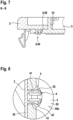
- Fig. 7 shows a sectional view of the wall arrangement, which can be seen in a section along the Fig. 2 drawn line BB.
- Fig. 9 shows a sectional view of the wall arrangement, which can be seen in a section along the Fig. 2 drawn line CC.
- Fig. 14 shows an enlarged, broken sectional view, with a section along the Fig. 2 drawn line CC.
- the wall arrangement 1 comprises a partition wall 2, an insulating part 3 and a fan 6, wherein the fan 6 consists of Fig. 2 in Fig. 9 omitted for reasons of clarity.
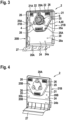
- the partition wall 2 is in the Figs. 3 and 4 shown in detail and serves, as already explained, to delimit a refrigeration compartment 110.
- the partition wall 2 has a flatly extending main wall 20 and an optional collar 21.
- the main wall 20 may have a rectangular perimeter which has two opposite first, straight Edge regions 20A and two second edge regions 20B which are opposite one another and extend transversely between the first edge regions 20A.
- the main wall 20 is generally implemented as a flatly extending component and has a first surface 20a and a second surface 20b which is opposite thereto and which is oriented towards the refrigeration compartment 110 when installed in a refrigeration device 100.
- the main wall 20 may, for example, have a first, plate-shaped portion 24 and a second portion 25 which recedes or projects relative to the first portion 24, as shown in the Figs. 3 and 4 is shown by way of example.
- the first section 24 can have a flat first surface 24a, wherein the second section 25 forms a depression 25A opposite the first surface 24a.
- the second section 25 can, for example, form an elevation 25B, as shown in Fig. 4 is shown by way of example.
- a bottom of the recess 25A is formed by a first surface 25a of the second section 25.
- the recess 25A or generally the second section 25 can have a polygonal circumference, eg a hexagonal circumference, as shown in the Figs. 3 and 4 shown by way of example.
- the first surface 24a of the first portion 24 and the first surface 25a of the second portion 25 form part of the first surface 20a of the main wall 20.
- the main wall 20 may have at least one first through-opening 26 extending between the first and second surfaces 20a, 20b of the main wall 20.
- first through-openings 26 may be provided, as shown in the Figs. 3 and 4
- the invention is not limited to this, however.
- it can optionally be provided that the first through openings 26 are formed in the second section 25 of the main wall 20.
- the first through openings 26 can be distributed or spaced apart along the circumference of the second section 25.
- an additional connection opening (not shown) can be provided in the main wall 20, in particular in the second section 25 of the main wall 20, in order to connect an icemaker unit (not shown) to it.
- the fan 6 is arranged on the first surface 20a of the main wall 20, eg in the second section 25 of the main wall 20.
- the fan 6 can, as in the Fign. 3 and 14 shown by way of example, be attached to the bottom of the recess 25A.
- several mounting pins 28 can be formed on the main wall 20, in particular on the bottom of the recess 25A, to which the fan 6 is fixed via corresponding recesses 68.
- the fan 6 can be positively connected to the pins 28, e.g. locked to them.
- damping elements (not shown), e.g.
- the fan 6 is, as shown in the Fign. 2 , 3 and 14 shown schematically, realized as a radial fan.
- the optional collar 21 may, for example, be formed integrally with the main wall 20 and protrudes from the first surface 20a of the main wall 20.
- the collar 21 can, for example, have a first plate- or web-shaped first collar portion 21A which extends along the first edge region 20A of the main wall 20.
- the collar 21 can optionally have two second collar portions 21B which extend transversely to the first collar portion 21A along the opposite second edge regions 20B of the main wall 20, as in Fig. 3 shown as an example.
- the second collar sections 21B can also be plate- or web-shaped.
- a retaining web 22 protruding from the collar 21 or from the first collar section 21A can be formed on the collar 21, in particular on the first collar section 21A.
- the retaining web 22 projects transversely from the first collar section 21A.
- the retaining web 22 can extend parallel to the first surface 20a of the main wall 20, in particular parallel to the first surface 24a of the first section 24.
- two retaining webs 22 can optionally be provided, which are spaced apart from each other along the first edge region 20A. In general, the retaining web 22 thus stands along the main wall 20 of the collar 21, wherein a receiving space is formed between the holding web 22 and the main wall 20.
- At least one first locking element 4 can be formed on the first surface 20a of the main wall 20.
- first locking elements 4 can be arranged in the first section 24 of the main wall 20, e.g. between an edge of the second section 25 and a second collar section 21B.
- the first locking elements 4 can be arranged at a distance from the first collar section 21A, for example by a distance which lies in a range between 20% and 80% of a distance of the first edge regions 20A of the main wall.
- the first locking elements 4 can be arranged at a distance from a region of the collar 21 in which the holding web 22 is formed.
- the at least one first locking element 4 can be formed on the first surface 24a of the first portion 24 of the main wall 20.
- the first locking element 4 can generally be realized as a projection 50 which protrudes from the first surface 20a of the main wall 20.
- the locking element 4 can have, for example, at least two separate, for example rod-shaped shaft pieces 41 that protrude from the first surface 20a of the main wall 20.
- the shaft pieces 41 are elastically deformable and thus movable relative to one another.
- each shaft piece 41 has a hook section or head 42 that protrudes transversely from it. This forms an undercut that allows a positive locking, e.g. in a recess 40.
- the partition wall 2 can further comprise an optional cover section 27 which is arranged at a lower edge region of the main wall 20 and protrudes from the second surface 20b of the main wall 20.
- the cover section 27 can be arc-shaped, as in the Figs. 3 and 4 is shown by way of example.
- the cover section 27 can be dimensioned such that a gap is formed between a bottom wall 112 delimiting the cold compartment 110 and the cover section 27, which forms a fluidically conductive connection between the cold compartment 110 and a rear side of the wall arrangement 1.
- the partition wall 2 can be made of a plastic material, such as polypropylene, PP, or an acrylonitrile-butadiene-styrene copolymer, ABS.
- the insulating part 3 is in the Figs. 5 and 6 As shown in the Figs. 5 and 6 As shown, the insulating part 3 can have a main body 30, optionally at least one second locking element 5 and an optional sealing collar 33.
- the main body 30 can in particular be plate-shaped and has a first surface 30a and a second surface 30b oriented opposite to this. As shown in the Figs. 5 and 6 As shown by way of example, the first and second surfaces 30a, 30b of the main body 30 can be flat or substantially flat.
- the main body 30 can have a peripheral shape which is adapted to a circumference defined by the collar 21 of the main wall 20 of the partition wall 2.
- the insulating part 3 is implemented as a flatly extending component.
- the optional sealing collar 33 of the insulating part 30 may be formed integrally with the main body 30 and protrudes from the first surface 30a of the main body 30.
- the sealing collar 33 can in particular form a closed frame.
- the circumferential profile defined by the sealing collar 33 can be designed to correspond to the circumference of the recess 25A, which is defined by the second section 25 of the main wall 20 of the partition wall 2.
- a sealing collar with a hexagonal circumference is therefore shown as an example.
- the insulating part 3 has a through-opening 36 which extends between the first and second surfaces 30a, 30b of the main body 30.
- the through-opening 36 may in particular have a circular circumference, as shown in the Figs. 5 and 6 shown as an example.
- the through-opening 36 can be provided within the area enclosed by the sealing collar 33 if the optional sealing collar 33 is provided. In this case, the optional sealing collar 33 surrounds the second through-opening 36.
- the insulating part 3 shown as an example has two optional second locking elements 5.
- more than two second locking elements 5 or only one second locking element 5 is provided.
- the second locking elements 5 can be arranged laterally between an edge of the main body 30 and the sealing collar 33.
- other positions of the locking elements 5 are also conceivable.
- the second locking elements 5 are designed as recesses 50, which are also referred to below as locking recesses 50.
- the locking recesses 50 can, for example, be through-openings which extend between the first and the second surface 30a, 30b of the main body 30, as shown in the Figs. 5 and 6 As shown in the Figs. 5 and 6 As shown in the Figs. 5 and 6 As is also shown, the locking recesses 50 can have a circular cross-section, for example.
- the second locking elements 5 are designed to correspond or complement the first locking elements 4 of the main wall 20, so that they can engage or lock into one another in a form-fitting manner.
- the insulating part 3 can in particular be made of expanded polypropylene, EPP for short, expanded polyethylene, EPE, or expanded polystyrene, EPS for short.
- the first locking elements 4 of the main wall 20 can be locked with the second locking elements 5 of the insulating part 3.
- the shaft pieces 41 protrude through the locking recess 50 and the head or hook 42 engages behind an area of the second surface 30b of the main body 30 of the insulating part 3 that surrounds the locking recess 50.
- the first surface of the main body 30 of the insulating part 3 faces the main wall 20 or the first surface 20a of the main wall 20 and can, for example, rest against the first surface 24a of the first section 24 of the main wall 20, as shown in Fig. 9 is shown as an example.
- an edge region 31 of the insulating part 3 or of the main body 30 can be arranged between the first surface 20a of the main wall 20 and the retaining web 22.
- the optional retaining web 22 thus defines the edge region 31 of the insulating part 3 in relation to a direction perpendicular to the first surface 20a of the main wall 20.
- the sealing collar 33 of the insulating part 3 can protrude into the recess 25A defined by the second section 25 of the main wall 20 or can be inserted into it.
- an end 33E of the sealing collar 33 facing away from the main body 30 can rest against the bottom of the recess 25A, as in Fig. 10 shown by way of example.
- a circumference of the sealing collar 33 of the insulating part 3, e.g. with a peripheral surface 33a can rest against the peripheral edge of the second section 25 or the recess 25A, as in Fig. 10 shown by way of example.
- the insulating part 3 is thus arranged on the first surface 20a of the main wall 20 such that a pressure chamber 65 is formed between the insulating part 3 and the main wall 20, which is delimited by the insulating part 3 and the main wall 20.
- the fan 6 is, as in Fig. 14 shown, arranged between the main wall 20 and the insulating part 3 in the pressure chamber 65. As shown in the Fign. 2 and 9 As shown by way of example, the fan 6 can be arranged within or overlapping the second through-opening 36 of the insulating part 3 with respect to a radial direction of the second through-opening 36 of the insulating part 3. For example, the fan 6 can be arranged flush or coaxial with the second through-opening 36.
- the pressure chamber 65 in which the fan 6 is arranged, is thus formed between the bottom of the recess 25 of the main wall 20 and the area of the first surface 30a of the main body 30 of the insulating part surrounded by the sealing collar 33.
- the sealing collar 33 improves the sealing of this space, so that a more efficient fluid transport through the first and second through-openings 26, 36 can take place by means of the fan 6.
- the evaporator 121 can be arranged on the second surface 30b of the insulating part 30, as in Fig. 14 shown schematically, in particular adjacent to the second through-opening 36.
- a further advantage of the described wall arrangement 1 is its ease of assembly.
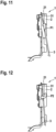
- the wall arrangement 1 can be assembled in a process whose sequence is shown schematically in Fig. 13 Individual assembly states are shown as examples in the Figs. 11 and 12 shown.
- the fan 6 is arranged on the partition wall 2, in particular on the first surface 20a of the main wall 20, e.g. in the recess 25A.
- the fan 6 can be fixed to the pins 28, as described above.
- the insulating part 3 is arranged on the first surface 20a of the main wall 20 such that the fan 6 is located between the main wall 20 and the insulating part 3.
- the sealing collar 33 can be partially inserted into the recess 25A or at least positioned opposite it.
- the insulating part 3 can be arranged on the partition wall 2 such that the first and second locking elements 4, 5 are positioned opposite each other.
- the first surface 30a of the main body 30 of the insulating part 3 and the first surface 20a of the main wall 20 of the partition wall 2 are arranged opposite each other.
- the edge region 31 of the insulating part 3 can first be introduced between the holding web 22 and the first surface of the main wall 20 by moving the edge region along the first surface 20a of the main wall 20, as shown in Fig. 11 symbolically represented by the arrow P1.
- the partition wall 2 and the insulating part 3 are connected or fastened to one another in a form-fitting manner.
- the first and second locking elements 4, 5 can be locked into one another.
- the projections 40 are pressed into the recesses 50 or the insulating part 3 is brought closer to the partition wall 2 so that the projections 40 are introduced into the recesses 40.
- the positions of the locking elements 4, 5 clearly determine the position of the insulating part 3 and the partition wall 2 in relation to one another, which facilitates assembly.
- the approach of the insulating part 3 and the partition wall 3 can, for example, take place after the edge region 31 of the insulating part 3 has been introduced between the retaining web 22 and the main wall 20. In this case, the insulating part 3 can be pivoted towards the first surface 20a of the main wall 20, as shown in Fig. 12 symbolically represented by the arrow P2, until the first and second locking elements 4, 5 engage with each other.
- the locking elements 4, 5 on the partition wall 2 and the insulating part 3 thus make it easier to position the parts relative to one another and thus to assemble them. Furthermore, the positive connection between the partition wall 2 and the insulating part 3, e.g. by means of the locking elements 4, 5, ensures a mechanically stable fastening. If the insulating part 3 is made of EPP or EPE, damage to the insulating part 3 during assembly is also effectively prevented and the insulating part 3 can also be easily removed from the partition wall 2.
Landscapes
- Engineering & Computer Science (AREA)
- Chemical & Material Sciences (AREA)
- Combustion & Propulsion (AREA)
- Physics & Mathematics (AREA)
- Mechanical Engineering (AREA)
- Thermal Sciences (AREA)
- General Engineering & Computer Science (AREA)
- Cold Air Circulating Systems And Constructional Details In Refrigerators (AREA)
- Refrigerator Housings (AREA)
Applications Claiming Priority (2)
| Application Number | Priority Date | Filing Date | Title |
|---|---|---|---|
| DE102020214145.2A DE102020214145A1 (de) | 2020-11-11 | 2020-11-11 | Wandungsanordnung für ein Kältegerät, Kältegerät sowie Verfahren zum Zusammenbau einer Wandungsanordnung |
| PCT/EP2021/073850 WO2022100906A1 (de) | 2020-11-11 | 2021-08-30 | Wandungsanordnung für ein kältegerät, kältegerät sowie verfahren zum zusammenbau einer wandungsanordnung |
Publications (2)
| Publication Number | Publication Date |
|---|---|
| EP4244554A1 EP4244554A1 (de) | 2023-09-20 |
| EP4244554B1 true EP4244554B1 (de) | 2024-11-27 |
Family
ID=77801680
Family Applications (1)
| Application Number | Title | Priority Date | Filing Date |
|---|---|---|---|
| EP21772715.5A Active EP4244554B1 (de) | 2020-11-11 | 2021-08-30 | Wandungsanordnung für ein kältegerät, kältegerät sowie verfahren zum zusammenbau einer wandungsanordnung |
Country Status (5)
| Country | Link |
|---|---|
| EP (1) | EP4244554B1 (pl) |
| CN (1) | CN116888418A (pl) |
| DE (1) | DE102020214145A1 (pl) |
| PL (1) | PL4244554T3 (pl) |
| WO (1) | WO2022100906A1 (pl) |
Families Citing this family (1)
| Publication number | Priority date | Publication date | Assignee | Title |
|---|---|---|---|---|
| CN119836554A (zh) * | 2022-12-14 | 2025-04-15 | 三星电子株式会社 | 板组件和家用电器 |
Citations (2)
| Publication number | Priority date | Publication date | Assignee | Title |
|---|---|---|---|---|
| CN106225378A (zh) * | 2016-07-29 | 2016-12-14 | 海信容声(扬州)冰箱有限公司 | 一种风冷冰箱风腔结构及风冷冰箱 |
| CH713416A2 (de) * | 2018-06-06 | 2018-08-15 | V Zug Ag | Kühlgerät mit Befestigungsmechanismus für ein Bauteil im Nutzraum. |
Family Cites Families (8)
| Publication number | Priority date | Publication date | Assignee | Title |
|---|---|---|---|---|
| JPS5930374Y2 (ja) * | 1980-12-03 | 1984-08-30 | 株式会社日立製作所 | 冷蔵庫 |
| JPS61168770A (ja) * | 1985-01-21 | 1986-07-30 | 三菱電機株式会社 | 冷蔵庫 |
| JP2537900B2 (ja) * | 1987-09-25 | 1996-09-25 | 松下冷機株式会社 | 冷却装置 |
| JP2937752B2 (ja) * | 1994-05-30 | 1999-08-23 | 株式会社東芝 | 冷蔵庫 |
| JP2996893B2 (ja) * | 1995-03-30 | 2000-01-11 | 株式会社東芝 | 冷却装置 |
| JP2006138609A (ja) * | 2004-11-15 | 2006-06-01 | Toshiba Corp | 冷蔵庫 |
| DE102009002446A1 (de) | 2009-04-16 | 2010-10-21 | BSH Bosch und Siemens Hausgeräte GmbH | Kältegerät und Innenbehälter dafür |
| DE102014015035A1 (de) | 2014-09-09 | 2016-03-10 | Liebherr-Hausgeräte Ochsenhausen GmbH | Kühl- und/oder Gefriergerät |
-
2020
- 2020-11-11 DE DE102020214145.2A patent/DE102020214145A1/de active Pending
-
2021
- 2021-08-30 CN CN202180075555.0A patent/CN116888418A/zh active Pending
- 2021-08-30 PL PL21772715.5T patent/PL4244554T3/pl unknown
- 2021-08-30 WO PCT/EP2021/073850 patent/WO2022100906A1/de not_active Ceased
- 2021-08-30 EP EP21772715.5A patent/EP4244554B1/de active Active
Patent Citations (2)
| Publication number | Priority date | Publication date | Assignee | Title |
|---|---|---|---|---|
| CN106225378A (zh) * | 2016-07-29 | 2016-12-14 | 海信容声(扬州)冰箱有限公司 | 一种风冷冰箱风腔结构及风冷冰箱 |
| CH713416A2 (de) * | 2018-06-06 | 2018-08-15 | V Zug Ag | Kühlgerät mit Befestigungsmechanismus für ein Bauteil im Nutzraum. |
Also Published As
| Publication number | Publication date |
|---|---|
| PL4244554T3 (pl) | 2025-06-02 |
| CN116888418A (zh) | 2023-10-13 |
| WO2022100906A1 (de) | 2022-05-19 |
| EP4244554A1 (de) | 2023-09-20 |
| DE102020214145A1 (de) | 2022-05-12 |
Similar Documents
| Publication | Publication Date | Title |
|---|---|---|
| EP3262357B1 (de) | Kältegerät | |
| EP4244554B1 (de) | Wandungsanordnung für ein kältegerät, kältegerät sowie verfahren zum zusammenbau einer wandungsanordnung | |
| DE102015204597A1 (de) | Haushaltskältegerät mit einem Randabschlussteile aufweisenden Fachboden | |
| EP3578905A1 (de) | Kühlgerät mit einem befestigungsmechanismus für ein bauteil im nutzraum | |
| EP2906888B1 (de) | Kältegerät mit einbauteil | |
| EP2697582A2 (de) | Einbau-kältegerät mit einem beschlagsbauteil | |
| DE102011087037A1 (de) | Wärmeisolationsgehäuse für ein Kältegerät | |
| EP2609383B1 (de) | Kältegerät mit einer traverse | |
| DE202018004467U1 (de) | Kältegerät mit Einbauteil | |
| WO2023088973A1 (de) | Kältegerät, verdampferbaugruppe für ein kältegerät, halter und verfahren zum fixieren einer sensoreinrichtung an einem rohr eines verdampfers | |
| EP4563920A1 (de) | Kältegerät und luftführungsanordnung für ein kältegerät | |
| DE102019216591A1 (de) | Kältegerätevorrichtung, Kühl- und/oder Gefriergerät und Verfahren zur Montage der Kältegerätevorrichtung | |
| WO2023166152A1 (de) | Kältegerät, wärmetauscherbaugruppe für ein kältegerät, verfahren zur montage eines ventilators in einem gehäuse sowie verfahren zur herstellung einer wärmetauscherbaugruppe | |
| EP3655714B1 (de) | Kältegerät mit umströmten verdampfer | |
| WO2023280575A1 (de) | Kältegerät und trennwandbaugruppe für ein kältegerät | |
| EP4310421A1 (de) | Kältegerät und halter zum fixieren von funktionskomponenten eines kältemittelkreislaufs in einem maschinenraum eines kältegeräts | |
| DE102021210802A1 (de) | Kältegerät, Verdichterbaugruppe für ein Kältegerät und Verfahren zum Montieren der Verdichterbaugruppe | |
| EP3311086B1 (de) | Kältegerätevorrichtung und verfahren zu einer montage einer kältegerätevorrichtung | |
| EP4341625A1 (de) | Kältegerät | |
| EP4310422A1 (de) | Kältegerät und halter zum fixieren von funktionskomponenten eines kältemittelkreislaufs in einem maschinenraum eines kältegeräts und verfahren zur montage des halters an einer tragvorrichtung | |
| DE102023201158A1 (de) | Kältegerät, Sockelbaugruppe für ein Kältegerät und Verfahren zum Montieren der Sockelbaugruppe | |
| DE102015219326A1 (de) | No-Frost-Kältegerät | |
| EP4056935A1 (de) | Hinterlegteil für ein haushaltskältegerätbauteil, anordnung mit einem haushaltskältegerätbauteil und einem hinterlegteil, sowie montageverfahren | |
| WO2012025565A2 (de) | Kältegerät mit einer traverse | |
| DE102021204151A1 (de) | Wärmetauscher für ein Kältegerät sowie Kältegerät |
Legal Events
| Date | Code | Title | Description |
|---|---|---|---|
| STAA | Information on the status of an ep patent application or granted ep patent |
Free format text: STATUS: UNKNOWN |
|
| STAA | Information on the status of an ep patent application or granted ep patent |
Free format text: STATUS: THE INTERNATIONAL PUBLICATION HAS BEEN MADE |
|
| PUAI | Public reference made under article 153(3) epc to a published international application that has entered the european phase |
Free format text: ORIGINAL CODE: 0009012 |
|
| STAA | Information on the status of an ep patent application or granted ep patent |
Free format text: STATUS: REQUEST FOR EXAMINATION WAS MADE |
|
| 17P | Request for examination filed |
Effective date: 20230612 |
|
| AK | Designated contracting states |
Kind code of ref document: A1 Designated state(s): AL AT BE BG CH CY CZ DE DK EE ES FI FR GB GR HR HU IE IS IT LI LT LU LV MC MK MT NL NO PL PT RO RS SE SI SK SM TR |
|
| DAV | Request for validation of the european patent (deleted) | ||
| DAX | Request for extension of the european patent (deleted) | ||
| GRAP | Despatch of communication of intention to grant a patent |
Free format text: ORIGINAL CODE: EPIDOSNIGR1 |
|
| STAA | Information on the status of an ep patent application or granted ep patent |
Free format text: STATUS: GRANT OF PATENT IS INTENDED |
|
| INTG | Intention to grant announced |
Effective date: 20240718 |
|
| GRAS | Grant fee paid |
Free format text: ORIGINAL CODE: EPIDOSNIGR3 |
|
| GRAA | (expected) grant |
Free format text: ORIGINAL CODE: 0009210 |
|
| STAA | Information on the status of an ep patent application or granted ep patent |
Free format text: STATUS: THE PATENT HAS BEEN GRANTED |
|
| AK | Designated contracting states |
Kind code of ref document: B1 Designated state(s): AL AT BE BG CH CY CZ DE DK EE ES FI FR GB GR HR HU IE IS IT LI LT LU LV MC MK MT NL NO PL PT RO RS SE SI SK SM TR |
|
| REG | Reference to a national code |
Ref country code: GB Ref legal event code: FG4D Free format text: NOT ENGLISH |
|
| REG | Reference to a national code |
Ref country code: CH Ref legal event code: EP |
|
| REG | Reference to a national code |
Ref country code: IE Ref legal event code: FG4D Free format text: LANGUAGE OF EP DOCUMENT: GERMAN |
|
| REG | Reference to a national code |
Ref country code: DE Ref legal event code: R096 Ref document number: 502021005950 Country of ref document: DE |
|
| REG | Reference to a national code |
Ref country code: LT Ref legal event code: MG9D |
|
| REG | Reference to a national code |
Ref country code: NL Ref legal event code: MP Effective date: 20241127 |
|
| PG25 | Lapsed in a contracting state [announced via postgrant information from national office to epo] |
Ref country code: IS Free format text: LAPSE BECAUSE OF FAILURE TO SUBMIT A TRANSLATION OF THE DESCRIPTION OR TO PAY THE FEE WITHIN THE PRESCRIBED TIME-LIMIT Effective date: 20250327 Ref country code: HR Free format text: LAPSE BECAUSE OF FAILURE TO SUBMIT A TRANSLATION OF THE DESCRIPTION OR TO PAY THE FEE WITHIN THE PRESCRIBED TIME-LIMIT Effective date: 20241127 Ref country code: PT Free format text: LAPSE BECAUSE OF FAILURE TO SUBMIT A TRANSLATION OF THE DESCRIPTION OR TO PAY THE FEE WITHIN THE PRESCRIBED TIME-LIMIT Effective date: 20250327 |
|
| PG25 | Lapsed in a contracting state [announced via postgrant information from national office to epo] |
Ref country code: FI Free format text: LAPSE BECAUSE OF FAILURE TO SUBMIT A TRANSLATION OF THE DESCRIPTION OR TO PAY THE FEE WITHIN THE PRESCRIBED TIME-LIMIT Effective date: 20241127 Ref country code: NL Free format text: LAPSE BECAUSE OF FAILURE TO SUBMIT A TRANSLATION OF THE DESCRIPTION OR TO PAY THE FEE WITHIN THE PRESCRIBED TIME-LIMIT Effective date: 20241127 |
|
| PG25 | Lapsed in a contracting state [announced via postgrant information from national office to epo] |
Ref country code: BG Free format text: LAPSE BECAUSE OF FAILURE TO SUBMIT A TRANSLATION OF THE DESCRIPTION OR TO PAY THE FEE WITHIN THE PRESCRIBED TIME-LIMIT Effective date: 20241127 |
|
| PG25 | Lapsed in a contracting state [announced via postgrant information from national office to epo] |
Ref country code: ES Free format text: LAPSE BECAUSE OF FAILURE TO SUBMIT A TRANSLATION OF THE DESCRIPTION OR TO PAY THE FEE WITHIN THE PRESCRIBED TIME-LIMIT Effective date: 20241127 |
|
| PG25 | Lapsed in a contracting state [announced via postgrant information from national office to epo] |
Ref country code: NO Free format text: LAPSE BECAUSE OF FAILURE TO SUBMIT A TRANSLATION OF THE DESCRIPTION OR TO PAY THE FEE WITHIN THE PRESCRIBED TIME-LIMIT Effective date: 20250227 |
|
| PG25 | Lapsed in a contracting state [announced via postgrant information from national office to epo] |
Ref country code: GR Free format text: LAPSE BECAUSE OF FAILURE TO SUBMIT A TRANSLATION OF THE DESCRIPTION OR TO PAY THE FEE WITHIN THE PRESCRIBED TIME-LIMIT Effective date: 20250228 Ref country code: LV Free format text: LAPSE BECAUSE OF FAILURE TO SUBMIT A TRANSLATION OF THE DESCRIPTION OR TO PAY THE FEE WITHIN THE PRESCRIBED TIME-LIMIT Effective date: 20241127 |
|
| PG25 | Lapsed in a contracting state [announced via postgrant information from national office to epo] |
Ref country code: RS Free format text: LAPSE BECAUSE OF FAILURE TO SUBMIT A TRANSLATION OF THE DESCRIPTION OR TO PAY THE FEE WITHIN THE PRESCRIBED TIME-LIMIT Effective date: 20250227 |
|
| PG25 | Lapsed in a contracting state [announced via postgrant information from national office to epo] |
Ref country code: SM Free format text: LAPSE BECAUSE OF FAILURE TO SUBMIT A TRANSLATION OF THE DESCRIPTION OR TO PAY THE FEE WITHIN THE PRESCRIBED TIME-LIMIT Effective date: 20241127 |
|
| PG25 | Lapsed in a contracting state [announced via postgrant information from national office to epo] |
Ref country code: DK Free format text: LAPSE BECAUSE OF FAILURE TO SUBMIT A TRANSLATION OF THE DESCRIPTION OR TO PAY THE FEE WITHIN THE PRESCRIBED TIME-LIMIT Effective date: 20241127 |
|
| PG25 | Lapsed in a contracting state [announced via postgrant information from national office to epo] |
Ref country code: EE Free format text: LAPSE BECAUSE OF FAILURE TO SUBMIT A TRANSLATION OF THE DESCRIPTION OR TO PAY THE FEE WITHIN THE PRESCRIBED TIME-LIMIT Effective date: 20241127 |
|
| PG25 | Lapsed in a contracting state [announced via postgrant information from national office to epo] |
Ref country code: RO Free format text: LAPSE BECAUSE OF FAILURE TO SUBMIT A TRANSLATION OF THE DESCRIPTION OR TO PAY THE FEE WITHIN THE PRESCRIBED TIME-LIMIT Effective date: 20241127 |
|
| PG25 | Lapsed in a contracting state [announced via postgrant information from national office to epo] |
Ref country code: SK Free format text: LAPSE BECAUSE OF FAILURE TO SUBMIT A TRANSLATION OF THE DESCRIPTION OR TO PAY THE FEE WITHIN THE PRESCRIBED TIME-LIMIT Effective date: 20241127 |
|
| PG25 | Lapsed in a contracting state [announced via postgrant information from national office to epo] |
Ref country code: CZ Free format text: LAPSE BECAUSE OF FAILURE TO SUBMIT A TRANSLATION OF THE DESCRIPTION OR TO PAY THE FEE WITHIN THE PRESCRIBED TIME-LIMIT Effective date: 20241127 |
|
| PG25 | Lapsed in a contracting state [announced via postgrant information from national office to epo] |
Ref country code: IT Free format text: LAPSE BECAUSE OF FAILURE TO SUBMIT A TRANSLATION OF THE DESCRIPTION OR TO PAY THE FEE WITHIN THE PRESCRIBED TIME-LIMIT Effective date: 20241127 |
|
| REG | Reference to a national code |
Ref country code: DE Ref legal event code: R097 Ref document number: 502021005950 Country of ref document: DE |
|
| PG25 | Lapsed in a contracting state [announced via postgrant information from national office to epo] |
Ref country code: SE Free format text: LAPSE BECAUSE OF FAILURE TO SUBMIT A TRANSLATION OF THE DESCRIPTION OR TO PAY THE FEE WITHIN THE PRESCRIBED TIME-LIMIT Effective date: 20241127 |
|
| PLBE | No opposition filed within time limit |
Free format text: ORIGINAL CODE: 0009261 |
|
| STAA | Information on the status of an ep patent application or granted ep patent |
Free format text: STATUS: NO OPPOSITION FILED WITHIN TIME LIMIT |
|
| REG | Reference to a national code |
Ref country code: CH Ref legal event code: L10 Free format text: ST27 STATUS EVENT CODE: U-0-0-L10-L00 (AS PROVIDED BY THE NATIONAL OFFICE) Effective date: 20251008 |
|
| PGFP | Annual fee paid to national office [announced via postgrant information from national office to epo] |
Ref country code: DE Payment date: 20250831 Year of fee payment: 5 |
|
| PGFP | Annual fee paid to national office [announced via postgrant information from national office to epo] |
Ref country code: TR Payment date: 20250822 Year of fee payment: 5 Ref country code: PL Payment date: 20250822 Year of fee payment: 5 |
|
| PGFP | Annual fee paid to national office [announced via postgrant information from national office to epo] |
Ref country code: AT Payment date: 20251020 Year of fee payment: 5 |
|
| 26N | No opposition filed |
Effective date: 20250828 |
|
| REG | Reference to a national code |
Ref country code: CH Ref legal event code: H13 Free format text: ST27 STATUS EVENT CODE: U-0-0-H10-H13 (AS PROVIDED BY THE NATIONAL OFFICE) Effective date: 20260324 |
|
| PG25 | Lapsed in a contracting state [announced via postgrant information from national office to epo] |
Ref country code: MC Free format text: LAPSE BECAUSE OF FAILURE TO SUBMIT A TRANSLATION OF THE DESCRIPTION OR TO PAY THE FEE WITHIN THE PRESCRIBED TIME-LIMIT Effective date: 20241127 |
|
| PG25 | Lapsed in a contracting state [announced via postgrant information from national office to epo] |
Ref country code: LU Free format text: LAPSE BECAUSE OF NON-PAYMENT OF DUE FEES Effective date: 20250830 |
|
| PG25 | Lapsed in a contracting state [announced via postgrant information from national office to epo] |
Ref country code: CH Free format text: LAPSE BECAUSE OF NON-PAYMENT OF DUE FEES Effective date: 20250831 |