EP4243441B1 - Tragbare vorrichtungen - Google Patents
Tragbare vorrichtungen Download PDFInfo
- Publication number
- EP4243441B1 EP4243441B1 EP22822843.3A EP22822843A EP4243441B1 EP 4243441 B1 EP4243441 B1 EP 4243441B1 EP 22822843 A EP22822843 A EP 22822843A EP 4243441 B1 EP4243441 B1 EP 4243441B1
- Authority
- EP
- European Patent Office
- Prior art keywords
- microphone
- concave section
- sound
- wearable device
- section
- Prior art date
- Legal status (The legal status is an assumption and is not a legal conclusion. Google has not performed a legal analysis and makes no representation as to the accuracy of the status listed.)
- Active
Links
Images


Classifications
-
- H—ELECTRICITY
- H04—ELECTRIC COMMUNICATION TECHNIQUE
- H04M—TELEPHONIC COMMUNICATION
- H04M9/00—Arrangements for interconnection not involving centralised switching
- H04M9/08—Two-way loud-speaking telephone systems with means for conditioning the signal, e.g. for suppressing echoes for one or both directions of traffic
- H04M9/082—Two-way loud-speaking telephone systems with means for conditioning the signal, e.g. for suppressing echoes for one or both directions of traffic using echo cancellers
-
- G—PHYSICS
- G02—OPTICS
- G02B—OPTICAL ELEMENTS, SYSTEMS OR APPARATUS
- G02B27/00—Optical systems or apparatus not provided for by any of the groups G02B1/00 - G02B26/00, G02B30/00
- G02B27/01—Head-up displays
- G02B27/017—Head mounted
- G02B27/0176—Head mounted characterised by mechanical features
-
- G—PHYSICS
- G02—OPTICS
- G02C—SPECTACLES; SUNGLASSES OR GOGGLES INSOFAR AS THEY HAVE THE SAME FEATURES AS SPECTACLES; CONTACT LENSES
- G02C11/00—Non-optical adjuncts; Attachment thereof
- G02C11/10—Electronic devices other than hearing aids
-
- H—ELECTRICITY
- H04—ELECTRIC COMMUNICATION TECHNIQUE
- H04R—LOUDSPEAKERS, MICROPHONES, GRAMOPHONE PICK-UPS OR LIKE ACOUSTIC ELECTROMECHANICAL TRANSDUCERS; ELECTRIC HEARING AIDS; PUBLIC ADDRESS SYSTEMS
- H04R1/00—Details of transducers, loudspeakers or microphones
- H04R1/02—Casings; Cabinets ; Supports therefor; Mountings therein
- H04R1/028—Casings; Cabinets ; Supports therefor; Mountings therein associated with devices performing functions other than acoustics, e.g. electric candles
-
- H—ELECTRICITY
- H04—ELECTRIC COMMUNICATION TECHNIQUE
- H04R—LOUDSPEAKERS, MICROPHONES, GRAMOPHONE PICK-UPS OR LIKE ACOUSTIC ELECTROMECHANICAL TRANSDUCERS; ELECTRIC HEARING AIDS; PUBLIC ADDRESS SYSTEMS
- H04R1/00—Details of transducers, loudspeakers or microphones
- H04R1/08—Mouthpieces; Microphones; Attachments therefor
- H04R1/083—Special constructions of mouthpieces
- H04R1/086—Protective screens, e.g. all weather or wind screens
-
- H—ELECTRICITY
- H04—ELECTRIC COMMUNICATION TECHNIQUE
- H04R—LOUDSPEAKERS, MICROPHONES, GRAMOPHONE PICK-UPS OR LIKE ACOUSTIC ELECTROMECHANICAL TRANSDUCERS; ELECTRIC HEARING AIDS; PUBLIC ADDRESS SYSTEMS
- H04R1/00—Details of transducers, loudspeakers or microphones
- H04R1/10—Earpieces; Attachments therefor ; Earphones; Monophonic headphones
- H04R1/105—Earpiece supports, e.g. ear hooks
-
- H—ELECTRICITY
- H04—ELECTRIC COMMUNICATION TECHNIQUE
- H04R—LOUDSPEAKERS, MICROPHONES, GRAMOPHONE PICK-UPS OR LIKE ACOUSTIC ELECTROMECHANICAL TRANSDUCERS; ELECTRIC HEARING AIDS; PUBLIC ADDRESS SYSTEMS
- H04R5/00—Stereophonic arrangements
- H04R5/027—Spatial or constructional arrangements of microphones, e.g. in dummy heads
-
- H—ELECTRICITY
- H04—ELECTRIC COMMUNICATION TECHNIQUE
- H04R—LOUDSPEAKERS, MICROPHONES, GRAMOPHONE PICK-UPS OR LIKE ACOUSTIC ELECTROMECHANICAL TRANSDUCERS; ELECTRIC HEARING AIDS; PUBLIC ADDRESS SYSTEMS
- H04R5/00—Stereophonic arrangements
- H04R5/033—Headphones for stereophonic communication
- H04R5/0335—Earpiece support, e.g. headbands or neckrests
-
- H—ELECTRICITY
- H04—ELECTRIC COMMUNICATION TECHNIQUE
- H04R—LOUDSPEAKERS, MICROPHONES, GRAMOPHONE PICK-UPS OR LIKE ACOUSTIC ELECTROMECHANICAL TRANSDUCERS; ELECTRIC HEARING AIDS; PUBLIC ADDRESS SYSTEMS
- H04R2410/00—Microphones
- H04R2410/07—Mechanical or electrical reduction of wind noise generated by wind passing a microphone
Definitions
- the present disclosure relates to a technical field of wearable devices.
- the present disclosure provides a wearable device, which has a better wearing experience as well as a better wind noise reduction effect.
- Document CN 214 704 204 U discloses glasses with temple comprising a temple body, the temple body has a connecting end and an erection end that are arranged oppositely, and the erection end is used to erect the temple on the auricle; an adjusting piece, the adjusting piece is detach-ably connected to the connecting end of the temple body; wherein, the adjusting member is replace ably connected to the temple body, so as to adjust the length of the temple by replacing the adjusting member with different specifications.
- Document CN203720476U U discloses Bluetooth sunglasses comprising a frame composed of a mirror frame and two temples, wherein the temple comprises a first temple for connecting the mirror frame, and a second body connected to the free end of the first temple a temple, the first leg includes a rear case for connecting the mirror frame, and a front case for fixing to the rear case, and a cavity for fixing the Bluetooth circuit board is formed between the front case and the rear case.
- the device further includes a plug-in earphone connected to the Bluetooth circuit board in the cavity by a lead wire; the position of the first temple connected to the second temple has a U shape for fixing a first bent portion of the plug-in earphone; a second curved portion in a U shape at a position on the second temple connected to the free end of the first curved portion, the first curved portion and the second curved portion, the overall shape is S.
- Document US2008008344 A discloses a spectacle type communication device characterized in that: in said communication device assuming a spectacle style, a bone conduction speaker separated from a main body of said communication device, which device comprises both an amplifier circuit and a battery, is supported in a manner such that said bone conduction speaker is mounted on a temple or an ear pad so as to be capable of being brought into contact with a tragus or a near area adjacent to a jaw joint slightly forward of said tragus; and, a connection part of a cable extending from said main body of said communication device is disposed on said temple or said ear pad.
- Document US2013142351 A1 discloses a communication device comprising a housing, the housing comprises a housing wall with an inner side and an outer side, and wherein the housing comprises a first housing part and a second housing part, which are joined along a dividing line, whereby a first abutment face of the first housing part abuts a second abutment face of the second housing part along the dividing line, a space bounded by the inner side of the housing wall, a first microphone transducer arranged in the housing, the first microphone transducer comprises a microphone opening, which is connected to the space, wherein the space is communicating with the surroundings via a peripheral line of housing openings in the outer side of the housing wall arranged along the dividing line, and housing channels extending between the housing openings and the inner side of the housing wall, and wherein the housing channels and the housing openings are provided as recessions in the first abutment face.
- the present disclosure provide a wearable device according to claim 1.
- the first microphone may be located at a bottom side of the downward depression region in the concave section.
- the first connecting section may include a first end portion and a second end portion, the second end portion may be connected to the concave section, a height of the first end portion relative to the bottom side of the concave section may be not greater than a height of the second end portion relative to the bottom side of the concave section.
- the second connecting section may include a third end portion and a fourth end portion, the third end portion may be connected to the concave section; a height of the third end portion relative to the bottom side of the concave section may be not less than a height of the fourth end portion relative to the bottom side of the concave section.
- the height of the second end portion relative to the bottom side of the concave section may be not less than the height of the third end portion relative to the bottom side of the concave section.
- the concave section may include a first connecting portion and a second connecting portion, the first connecting portion may be obliquely connected to the first connecting section and extends downward, the second connecting portion may be obliquely connected to the second connecting section and extends downward, an end of the first connecting portion away from the first connecting section may be connected to an end of the second connecting portion away from the second connecting section.
- a distance between the first connecting portion and the second connecting portion may decrease gradually along a depressed direction of the concave section.
- the wearable device further includes a sound conduction structure configured to transmit external sound, the sound conduction structure is connected to the concave section, the sound conduction structure is an internal through structure, one end of the sound conduction structure is connected to external environment, and the first microphone may be located at another end of the sound conduction structure.
- a plurality of sound conduction channels may be arranged inside the sound conduction structure and the plurality of sound conduction channels may be obliquely connected in sequence.
- the sound conduction structure may include a cavity, the cavity may be connected to external via a connecting hole.
- the sound conduction structure may include a plurality of cavities, the plurality of cavities may be distributed at intervals along a length direction of the sound conduction structure, adjacent cavities may be connected to each other by a connecting hole; a dimension of the cavity along a width direction of the sound conduction structure may be larger than a dimension of the connecting hole along the width direction of the sound conduction structure.
- the second connecting section may be provided with a second microphone.
- a connection line between the first microphone and the second microphone points to a direction of mouth of the user.
- a vibration direction of a diaphragm in the first microphone may be substantially perpendicular to a vibration direction of a diaphragm in the second microphone.
- a distance between the first microphone and the second microphone may be 5 mm-70 mm.
- the wearable device may further include an acoustic output unit, the acoustic output unit may be located at the concave section.
- a vibration direction of a diaphragm of the first microphone may be substantially perpendicular to a vibration direction of a diaphragm of the acoustic output unit.
- the first microphone or the second microphone of the wearable device may be located in an acoustic zero region of the acoustic output unit.
- the deflector structure may include a first deflector structure and a second deflector structure, the first deflector structure and the second deflector structure may be placed on a left ear and a right ear of the user, respectively.
- the device may further include a visual member, the visual member may be connected to a first connecting section of the first deflector structure or the second deflector structure.
- the wearable device may include a deflector structure configured to be worn on the head of a user.
- the deflector structure may be an eyewear leg or a partial structure thereof.
- the deflector structure may include a first connecting section, a second connecting section, and a concave section. The first connecting section, the concave section, and the second connecting section may be connected in sequence. The concave section may be located between the first connecting section and the second connecting section, wherein the concave section has a downward depression relative to the deflector structure.
- the wearable device may further include a first microphone configured to collect a sound signal generated when the user speaks, the first microphone may be located at the concave section. In some embodiments, the first microphone may be located inside the concave section, and the first microphone may pick up, through a sound inlet hole at the concave section, the sound signal when the user speaks.
- the wearable device may be an electronic device with audio functions (e.g., glasses, a smart helmet, etc.). When the user wears the wearable device for sports or in windy weather, the deflector structure may change an airflow direction and generate a low-flow rate region in the concave section that is depressed downward relative to the deflector structure.
- the deflector structure in the wearable device provided by embodiments of this present disclosure has a better wind-noise canceling effect, for example, the noise reduction effect of conventional multi-microphone arrays or bone conduction microphones can be achieved by using only dual air-conduction microphones.
- the small size of the wearable device provided by the embodiments of this present disclosure only requires a portion of the structure of the wearable device (e.g., the mirror legs) to be adjusted to a similar structure of the deflector structure.
- the wearable device provided by the embodiment of this present disclosure reduces wind noise by physical means, which is less damaging to the voice signal (e.g., the voice signal when the user is speaking) and leaves more room for subsequent algorithmic processing.
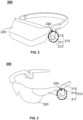
- FIG. 1 is a diagram illustrating an exemplary framework of a wearable device according to some embodiments of the present disclosure.
- the wearable device 100 may include a deflector structure 110, a visual member 120, and a microphone 130.
- the deflector structure 110 may be a component worn on the head of the user.
- the deflector structure 110 may be a component such as a mirror leg or headband.
- the wearable device 100 may include a visual member 120 and two deflector structures 110, and the two deflector structures 110 may be attached with the two ends of the visual member and placed on the corresponding left and right ears, respectively.
- the deflector structure 110 is a headband-type component
- the headband-type component may be adjusted to fit the head shape of the user, and a variety of functional components may also be provided thereon
- the wearable device 100 may include one visual member and one deflector structure 110, and the two ends of the deflector structure 110 may be connected to the two ends of the visual member.
- the structure of the deflector structure 110 may be adapted according to the type of wearable device 100 or the specific application scenario.
- the deflector structure 110 may include a first connecting section, a second connecting section, and a concave section, wherein the first connecting section, the concave section, and the second connecting section may be connected in sequence, the concave section may be located between the first connecting section and the second connecting section, and the concave section has a downward depression relative to the deflector structure 110.
- the deflector structure 110 may serve as a deflector structure for the wearable device 100, through which the wearable device 100 may be worn on the head of the user.
- the deflector structure 110 may change the airflow direction and generate a low-flow rate region in the concave section depressed downward relative to the deflector structure 110. Setting the microphone 130 in the concave section can significantly reduce the impact of external airflow on the sound signal when the user speaks and improve the user's experience.
- the wearable device 100 may also include a visual member 120.
- the visual member 120 may be configured to be placed on a part of the user's body, for example, the visual member 120 may be configured to be placed in a position such as the eye.
- the deflector structure 110 may be connected to one or both ends of the visual member 120 for keeping the wearable device 100 in steady contact with the user.
- the visible member 120 may be a lens, a display, or a display with a lens effect.
- the visible member 120 may also be a lens and its auxiliary components or a display and its auxiliary components, wherein the auxiliary components may be components such as a frame or a holder.
- the visible member 120 may also be an auxiliary component that does not contain a lens or display.
- the microphone 130 may convert the sound signal into a signal containing sound information.
- the microphone 130 may include one or more air conduction microphones.
- the microphone 130 may include one or more bone conduction microphones.
- the microphone 130 may include a combination of both one or more air conduction microphones and one or more bone conduction microphones.
- At least one microphone may be located at the concave section of the deflector structure 110, or the corresponding sound inlet hole of the microphone may be located at the concave section of the deflector structure, and the concave section may provide a low-flow rate region, and the location of the microphones 130 in the low-flow rate region can significantly reduce the impact of external airflow on the sound signal when the user speaks and improve the user's experience.
- the microphone 130 may also be located at another location of the deflector structure 110, for example, at a second connecting section of the deflector structure 110.
- the microphone 130 may be provided on the external surface of the deflector structure 110 or on the internal of the deflector structure 110.
- the microphone 130 may be provided at a location on the external surface of the deflector structure 110 near the mouth of the user.
- the deflector structure 110 may include a cavity for housing the microphone 130, the cavity may be connected to the external environment through a sound inlet hole, at least a portion of the microphone 130 may be housed in the cavity, and the microphone 130 may pick up the external sound signal through the sound inlet hole.
- the microphone 130 and the deflector structure 110 may be of an integral part.
- the type of microphone 130 may include at least one of a dynamic microphone, a condenser microphone, an aluminum ribbon microphone, a piezoelectric microphone, a vacuum tube microphone, etc.
- the wearable device 100 may also include an acoustic output unit (not shown in FIG. 1 ).
- the acoustic output unit may be configured to convert a signal containing sound information into a sound signal.
- the acoustic output unit may include one or more air conduction speakers.
- the acoustic output unit may include one or more bone conduction speakers.
- the acoustic output unit may include a combination of both one or more bone conduction speakers and one or more air conduction speakers.
- the acoustic output unit may be provided at the deflector structure 110 to facilitate the delivery of the emitted sound to the user.
- the acoustic output unit may be provided at an end of the deflector structure 110 or at any other location.
- the acoustic output unit may be provided at the end of the deflector structure 110, while no other acoustic output unit is not provided at other locations of the deflector structure 110.
- the plurality of acoustic output units may be provided at a plurality of locations in the deflector structure 110.
- at least one acoustic output unit is provided at both the end or other locations of the deflector structure 110.
- the acoustic output unit may be provided on the external surface of the deflector structure 110 or on the internal of the deflector structure 110.
- the acoustic output unit may be provided close to the location where the deflector structure 110 is in contact with the user (e.g., on the deflector structure 110 near the temple to the ear).
- the deflector structure 110 may include a cavity for housing the acoustic output unit, and at least a portion of the acoustic output unit may be housed in the cavity.
- the acoustic output unit and the deflector structure 110 may be an integral part. It should be noted that when the acoustic output unit is a bone conduction speaker, the acoustic output unit may produce air conduction sound waves while outputting mechanical vibrations (i.e., bone conduction sound waves).
- an electrical signal i.e., a signal containing sound information
- a vibration member of the acoustic output unit which conducts mechanical vibration through a vibration transmission element to transmit sound waves.
- the type of acoustic output unit may include one or more of moving coil, electrostatic, piezoelectric, moving iron, pneumatic, electromagnetic, etc.
- the framework diagram provided in FIG. 1 is for illustrative purposes only and is not intended to limit the scope of the present disclosure.
- various variations and modifications can be made under the guidance of this present disclosure. And these deformations and modifications will fall within the scope of the present disclosure.
- the count of elements shown in the figures can be adjusted according to the actual situation.
- one or more of the elements shown in FIG. 1 may be omitted, or one or more other elements may be added or removed.
- the wearable device 100 may also include an acoustic output unit.
- a component may be replaced by other components capable of performing similar functions.
- one component may be split into a plurality of subcomponents, or a plurality of components may be merged into a single component.
- FIG. 2 is a schematic diagram illustrating a structure of a wearable device according to some embodiments of the present disclosure.
- the wearable device 200 shown in FIG. 2 is a VR device or an AR device, and as shown in FIG. 2 , the wearable device 200 may include a deflector structure 210, a visual member 220, and a first microphone 230.
- the deflector structure 210 may be a headband-type component, and the deflector structure 210 may be a structure made of resilient material or a structure with an adjustable length.
- the two ends of the deflector structure 210 may be connected to the two ends of the visual member 220, and when the user wears the wearable device 200, the deflector structure 210 and the visual member 220 may surround the head of the user, and the wearable device 200 may be worn through the pressure of the deflector structure 210 and the visual member 220 on the head of the user.
- the connection between the deflector structure 210 and the visible member 220 may include, but is not limited to, a movable connection, such as a rotating connection or a telescoping connection, or a relatively fixed connection such as a snap, screwed or one-piece molded connection.
- the deflector structure 210 may include a first connecting section 211, a concave section 212, and a second connecting section 213 connected in sequence, wherein one end of the first connecting section 211 may be connected to the visible member 220, another end of the first connecting section 211 may be connected to the concave section 212, and the second connecting section 213 may be connected to the end of the concave section 212 that is away from the visible member 220.
- the second connecting section 213 may be a structure similar to a headband to wrap around the head of the user.
- the second connecting section 213 may be a structure independent from the headband, for example, the headband may be detachably connected to (e.g., clamped on, bonded to, etc.) the second connecting section 213.
- the concave section 212 may be located near the user's ear (e.g., front side, upper side, etc.), which allows the first microphone 230 to be located close to the user's mouth for easy reception of the sound signal when the user speaks.
- the acoustic output unit can be located close to the user's ear without blocking the user's ear canal opening, so that the user can hear the sound from the acoustic output unit while also receiving the sound from the external environment.
- the region of the concave section 212 that is depressed downward relative to the deflector structure 210 has a relatively low airflow rate relative to other locations (e.g., the first connecting section 211, the second connecting section 213, or the external environment).
- the first microphone 230 may be located inside the concave section 212, with the sound inlet hole opened in the side wall corresponding to the depression region, and the first microphone 230 picks up the external sound signal through the sound inlet hole.
- the concave section 212 has a cavity inside that is connected to the external environment through a sound inlet hole, and the first microphone 230 or its components (e.g., a diaphragm, a transducer, etc.) may be located in this cavity, at which point the lower concave section 212 may be considered a housing structure for the first microphone.
- the airflow rate may be lower when the distance from downward depression region of the concave section 212 to the top of the deflector structure 210 is increased.
- the sound inlet hole may be located at the bottom side of the downward depression region in the concave section 212.
- the first microphone 230 may also be located in an external region of the concave section 212.
- the first microphone 230 may be a relatively independent structure relative to the concave section 212, with the housing structure of the first microphone 230 connected to the side wall of the concave section 212.
- a sound inlet hole may be opened in the housing structure of the first microphone 230 to allow the internal elements of the first microphone 230 to pick up external sound signals, and descriptions about the location of the sound inlet hole opened in the housing structure of the first microphone 230 may refer to the contents about the sound inlet hole in the side wall of the concave section 212 described above.
- the first microphone 230 can be a single microphone or a microphone array consisting of multiple microphones.
- the wearable device 200 may include microphones other than the first microphone 230, such as a second microphone, a third microphone, etc.
- the other microphones may be located at other parts of the inflow structure 210, for example, the other microphones may be located at the second connection segment 213 of the deflector structure, and the multiple microphones (e.g., dual microphones, triple microphones, etc.) on the wearable device 200 may further improve the call noise reduction effect.
- FIG. 3 is a schematic diagram illustrating a structure of another wearable device according to some embodiments of the present disclosure.
- the wearable device 300 shown in FIG. 3 may be an eyewear, and as shown in FIG. 3 , the wearable device 300 may include two deflector structures 310, a visual member 320 (i.e., frames or lenses), and a first microphone 330.
- the deflector structure 310 may be considered as a mirror leg structure, with one end of the deflector structure 310 (i.e., a first connector 311) connected to the end of the visible member 320, and two second connector segments 313 of the deflector structure 310 matching with the user's left and right ears, respectively.
- a connection manner of the deflector structure 310 to the visible member 320 may include, but is not limited to, a movable connection such as a rotating connection or a telescoping connection, or a relatively fixed connection such as a snap, screwed or one-piece molded connection.
- the structure of the first connecting section 311, the concave section 312, and the first microphone 330 shown in FIG. 3 may be similar to the structure of the first connecting section 211, the concave section 212, and the first microphone 230 shown in FIG. 2 , and may not be described herein.
- the above description of the wearable device 200 and the wearable device 300 is for example and illustration purposes only and does not limit the scope of application of this present disclosure.
- various corrections and changes can be made to the wearable device 200 and the wearable device 300 under the guidance of this present disclosure.
- these corrections and modifications are still within the scope of the present disclosure.
- the deflector structure 210 of the wearable device 200 may be a mirror leg structure
- the deflector structure 310 of the wearable device 300 may be a headband-type component.
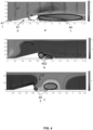
- FIG. 4 is a schematic diagram illustrating flow fields of different airflow directions according to some embodiments of the present disclosure
- a height of a deflector structure 410 may gradually increase, and then gradually decrease along the length of the deflector structure 410 (in a direction of the arrow x in the image a in FIG. 4 ), and the slope of a plane having a gradually increasing height ( plane A shown in the image a in FIG.
- plane A in the deflector structure 410 may be less than the slope of a plane having a gradually decreasing height (plane B shown in the image a in FIG. 4 , hereinafter referred to as plane B).
- the height of the deflector structure 410 may refer to a height of the deflector structure 410 in the z-direction relative to a reference plane 411.
- the slope may refer to a ratio of the height of the plane of the deflector structure 410 relative to the reference plane 411 to the distance in the horizontal direction.
- the deflector structure 410 may be set along a flow direction L1 of the airflow, where the flow rate of the airflow is 10 m/s, and the length direction of the deflector structure 410 may be the same as the flow direction L1 of the airflow, which can also be understood as an angle between the flow direction L1 of the airflow and the reference plane 411 is 0°.
- the deflector structure 410 may change the flow direction of the airflow, when the airflow first flows along the external surface of the gradually increasing height part of a raised structure 412, the height of the deflector structure 410 with the gradually increasing part can ensure a relatively smooth flow of airflow and prevent the airflow from generating eddy currents and introducing additional noise.
- the slope of the plane B in the deflector structure 410 is greater than the slope of the plane A, when the airflow passes the highest point of the deflector structure 410, the height of the deflector structure 410 changes abruptly, so that the airflow does not flow along the plane B of the deflector structure 410, but flows along the length of the deflector structure 410, which in turn forms a low flow rate region 401 in the deflector structure 410.
- the 0.15 mm height of the deflector structure 410 along the length of the deflector structure 410 can ensure that the flow rate in the region of about 1.5 mm after it is less than 2 m/s.
- a low flow rate region 402 may be formed along the length of the deflector structure 410 in a region of about 0.4 mm after the deflector structure 410.
- a length range of the low-flow rate region 402 may be significantly reduced relative to the length range of the low-flow rate region 401 in the image a in FIG. 4 , and there may also be a relatively high-speed reflux region in it.
- FIG. 4C when an angle between the flow direction L3 of the airflow and the reference plane is 90°, a low flow rate region 403 may be formed after the deflector structure 410 along the length of the deflector structure 410.
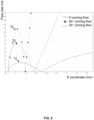
- FIG. 5 is a schematic diagram illustrating a flow rate variation curve according to some embodiments of the present disclosure.
- the horizontal coordinate (“x-coordinate (mm)” shown in FIG. 5 ) may correspond to the horizontal coordinate in FIG. 4
- the vertical coordinate may indicate an airflow rate (m/s) relative to the different locations.
- a curve 51 (a curve labeled "0° incoming flow” in FIG. 5 ) may refer to a flow rate variation curve at different locations when the angle between the flow direction and the reference surface 411 is 0°
- a curve 52 (a curve labeled "60° incoming flow” in FIG.
- a curve 53 (the curve labeled "90° incoming flow” in FIG. 5 ) may refer to a flow rate variation curve at different locations when the angle between the flow direction and the reference surface 411 is 90°.
- the angle between the flow direction of the airflow e.g., the flow direction L1 of the airflow in the image a in FIG.
- the horizontal coordinate may be within a range of 0.8 mm-1.8 mm, which indicates a low-flow rate (e.g., less than 2.2 m/s), wherein the very small values of the airflow rate are at 0.8 mm-0.85 mm and 1.4-1.6 mm in the x coordinate.
- the flow direction of the airflow for example, the flow direction L1 of the airflow in FIG. 4 , FIG. b
- the minimum value of the airflow rate may be at 0.8 mm-0.85 mm and 1.1-1.2 mm in the x coordinate.
- the angle of the flow direction of the airflow and the reference plane 411 is 90°
- the minimum value of the airflow rate may be at 0.8 mm-0.85 mm and 1.2-1.4 mm in the x coordinate.
- the deflector structure 410 may provide a corresponding low-flow rate region when facing airflow in different incoming directions.
- the location of the low-flow rate region (e.g., less than 2.2 m/s) in the deflector structure 410 has some variability when facing airflow in different incoming directions.
- the mounting location of the microphone or the sound inlet hole corresponding to the microphone may be adapted to the different application scenarios of the wearable device. For example, when a user wears a wearable device for running or cycling, the direction of external airflow may be mainly in the direction opposite to the user's movement.
- the deflector structure 410 can be specifically set, for example, the height direction of the deflector structure (e.g., a direction of the arrow y shown in the image a in FIG. 4 ) may be perpendicular or approximately perpendicular to the direction of the user's movement, thereby ensuring that the inlet aperture corresponding to the microphone is in the low-flow rate region.
- the height direction of the deflector structure e.g., a direction of the arrow y shown in the image a in FIG. 4
- the deflector structure 410 can be specifically set, for example, the height direction of the deflector structure (e.g., a direction of the arrow y shown in the image a in FIG. 4 ) may be perpendicular or approximately perpendicular to the direction of the user's movement, thereby ensuring that the inlet aperture corresponding to the microphone is in the low-flow rate region.
- the present disclosure also provides a deflector structure in FIGs. 6 to 12 and their corresponding contents.
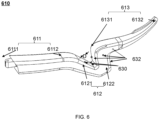
- FIG. 6 is a schematic diagram illustrating a deflector structure according to some embodiments of the present disclosure.
- the deflector structure 610 may include a first connecting section 611, a concave section 612, and a second connecting section 613 connected in sequence, wherein the concave section 612 has a downward depression region relative to the deflector structure 610.
- the first connecting section 611 and the second connecting section 613 may have rod-like structures.
- the first connecting section 611 may include a first end portion 6111 and a second end portion 6112.
- the first end portion 6111 may be configured to connect to the visible member of the wearable device, and the second end portion 6112 may be connected to the end of the concave section 612 away from the second connecting section 613.
- the second connecting section 613 may include a third end portion 6131 and a fourth end portion 6132.
- the third end portion 6131 may be connected to an end of the concave section 612 away from the first connecting section 611.
- the concave section 612 may include a first connecting portion 6121 and a second connecting portion 6122, the first connecting portion 6121 may be obliquely connected to the second end portion 6112 of the first connecting section 611 and extending downward, the second connecting portion 6122 may be obliquely connected to the third end portion 6131 of the second connecting section 613 and extending downward, the end of the first connecting portion 6121 away from the first connecting section 611 may be connected to the end of the second connecting portion 6122 away from the second connecting section 613, thereby forming a region having a downward depression region relative to the deflector structure 610.
- a distance between the first connecting portion 6121 and the second connecting portion 6122 may decrease gradually along a depressed direction of the concave section 612.
- the distance between the first connecting portion 6121 and the second connecting portion 6122 may be a distance between the sidewalls positioned opposite each other in the first connecting portion 6121 and the second connecting portion 6122 along the length of the deflector structure 610 (characterized by the "D" shown in the figure).
- the shape of the concave section 612 formed by the first connecting portion 6121 and the second connecting portion 6122 may be other shapes such as a circular arc, a quadrilateral (e.g., an inverted trapezoid), a V-shape, etc.
- the shape of the lower concave section 612 is not limited to the above-mentioned shape, but can be any shape that can achieve that the first connecting portion 6121 and the second connecting portion 6122 form a downward depression region relative to the deflector structure 610.
- FIG. 7 For more information about the specific shape of the concave section 612, please refer to FIG. 7 and relevant descriptions.
- One or more downward depression regions relative to the deflector structure 610 may be formed in the deflector structure 610 by providing a first connecting section 611, a second connecting section 613, and a concave section 612, which may provide a stable low-flow rate region in a particular airflow direction.
- the first connecting section 611 of the deflector structure 610 may direct the air to a position higher than the deflector structure 610, so that the depression region at the concave section 612 is a low-flow rate region.
- the air flow direction when the air flow direction is perpendicular to the length direction of the deflector structure 610, the air flow may flow out from both sides of the concave section 612 that are perpendicular to the length direction of the vertical deflector structure 610 due to the action of the concave section 612, and the bottom side of the depression region in the concave section 612 may be a stagnant region of the air flow.
- Setting the first microphone corresponding to the first sound inlet hole 630 at this region can reduce the influence of external airflow on the first microphone.
- the first microphone may be located inside the concave section 612.
- the concave section 612 has a cavity that is connected to the external environment through a first sound inlet hole 630, and the components of the first microphone (e.g., a diaphragm, a transducer, etc.) may be located in this cavity, and the lower concave section 212 may be considered a housing for the first microphone.
- the first microphone may be a separate component relative to the concave section 612.
- the first microphone may include a housing, which is connected to the concave section 612, and the diaphragm, the transducer, and other components of the first microphone are located in the housing, which may include a first sound inlet hole 630 through which external sound may act on the diaphragm of the first microphone.
- the first sound inlet hole 630 corresponding to the first microphone may be located on the side wall corresponding to the depression region.
- the first microphone corresponding to the first sound inlet hole 630 may be located at the bottom side of the depression region in the concave section 612.
- the first microphone may be made less susceptible to external airflow by adjusting the height of the first sound inlet hole 630 relative to the bottom side of the depression region.
- a ratio of a distance from the first sound inlet hole 630 to the bottom side of the depression region to a distance from the second end portion 6112 to the bottom side of the depression region may range from 0-1.
- the ratio of the distance from the first sound inlet hole 630 to the bottom side of the depression region to the distance from the second end portion 6112 to the bottom side of the depression region may range from 0-0.8.
- the ratio of the distance from the first sound inlet hole 630 to the bottom side of the depression region to the distance from the second end portion 6112 to the bottom side of the depression region may range from 0-0.5.
- the ratio of the distance from the first sound inlet hole 630 to the bottom side of the depression region to the distance from the second end portion 6112 to the bottom side of the depression region may range from 0-0.2. It should be noted that the distance from the first sound inlet hole 630 to the bottom side of the depression region may be a minimum distance from the first sound inlet hole 630 to the plane where the bottom part of the depression region is located when the user is wearing the wearable device. The distance from the second end portion 6112 to the bottom side of the depression region is the distance from the highest point of the second end portion 6112 to the plane where the bottom side of the depression region is located when the wearable device is worn by the user.
- the bottom side of the depression region may be a flat, convex, concave or irregular surface.
- the plane where the bottom side of the depression region is located may be determined by connecting the boundaries of the bottom side of the first connecting portion 6121 with the second connecting portion 6122 and the depression region.
- the wearable device may also include one or more second microphones, and a second sound inlet hole 632 corresponding to the second microphone(s) may be located at the second connecting section 613.
- the second sound inlet hole 632 corresponding to the second microphone(s) may also be located at the second connecting portion 6122 of the concave section 612.
- the second sound inlet hole 632 corresponding to the second microphone(s) may be located on the side wall of the depression region corresponding to the second connecting portion 6122.
- the second microphone 623 may be located on the side of the second connecting portion 6122 that is back away from the depression region.
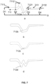
- FIG. 7 is a schematic diagram illustrating a structure of a deflector structure according to some embodiments of the present disclosure.
- a concave section 712a has an approximate V-shaped structure.
- the height of the first end portion 7111 of the first connecting portion 711 relative to the bottom side of the concave section 712a may be not greater than the height of the second end portion 7112 relative to the bottom side of the concave section 712a.
- the height of the first end portion 7111 relative to the bottom side of the concave section 712a may refer to a distance D1 between the upper end face of the first end portion 7111 and the plane in which the bottom side of the concave section 712a is located.
- the height of the second end portion 7112 relative to the bottom side of the concave section 712a may refer to a distance D2 between the upper end face of the second end portion 7112 and the plane in which the bottom side of the concave section 712a is located.
- the plane in which the bottom side of the concave section 712 is located (indicated by a dotted dashed line O in FIG.
- a height of the third end portion 7131 relative to the bottom side of the concave section 712a may be not less than a height of the fourth end portion 7132 relative to the bottom side of the concave section 712a.
- the height of the third end portion 7131 relative to the bottom side of the concave section 712a may be a distance D3 between the upper end face of the third end portion 7131 and the plane (i.e., the plane O) in which the bottom side of the concave section 712a is located.
- the height of the fourth end portion 7132 relative to the bottom side of the concave section 712a may be a distance D4 between the upper end face of the fourth end portion 7132 and the plane (i.e., the plane O) in which the bottom side of the concave section 712a is located.
- a height of the second end portion 7111 relative to the bottom side of the concave section 712a may be not less than the height of the third end portion relative to the bottom side of the concave section, that is, the distance D2 is not less than the distance D3.
- the deflector structures shown in images b, c, and d in FIG. 7 may be substantially the same as those in the image a in FIG. 7 , and the difference is the deflector structures in the images b, c, and d have different concave sections.
- the concave section 712b has structure similar to an inverted trapezoid, such that the concave section 712b forms a low flow rate region similar to the inverted trapezoidal region.
- the concave section 712c if the concave section 712c is circular, the concave section 712c may form a circular low-flow rate region.
- the concave section 712d may form a W-like low-flow rate region.
- the first connecting section, the second connecting section, and the height between their ends and the base in FIGs. 7B-7D please refer to descriptions about the image a in FIG. 7 above.
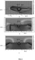
- FIG. 8 is a schematic diagram illustrating flow fields of different flow directions according to some embodiments of the present disclosure. The following descriptions take a concave section having a V-shaped structure as an example. As shown in the image a in FIG. 8 , the deflector structure is set along the flow direction of the airflow, wherein the flow rate of the airflow is 10 m/s, and the length direction of the deflector structure is the same as the flow direction of the airflow.
- the first connecting section 811 of the deflector structure may change the flow direction of the airflow, and the flow direction of the airflow changes under the action of the first end of the first connecting section 811.
- a portion of the airflow acting on the first end of the first connecting section 811 flows along the location above the first connecting section 811, continues to flow in the direction of the length of the deflector structure when it passes through the concave section 812 and forms a low flow rate region 814 in the depression region of the concave section 812.
- the airflow may flow out from both sides of the concave section 812 that are perpendicular to the length direction of the deflector structure due to the action of the concave section 812, and the bottom side of the depression region in the concave section 812 is the stagnant region of the airflow (e.g., the region 815 shown in the image b in FIG. 8 and the region 816 shown in the image c in FIG. 8 ).
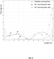
- FIG. 9 is a schematic diagram illustrating a flow rate variation curve according to some embodiments of the present disclosure.
- the horizontal coordinate may indicate the length (mm), where the length may be a length of a path of an object starting at the second end portion 8112 (illustrated in FIG. 8 ) and moving along the surface of the side wall corresponding to the depression region in the concave section.
- the vertical coordinate may indicate an airflow rate (m/s) at different locations having different distances with respect to the second end portion.
- a curve 91 (the curve marked by "parallel incoming flow" in FIG.
- a curve 92 (the curve marked by "60° incoming flow rate” in FIG. 9 ) is a flow rate variation curve at different locations when the angle between the flow direction and the length direction of the deflector structure is 60°
- a curve 93 (the curve marked by "90° incoming flow rate” in FIG. 9 ) is a flow rate variation curve at different locations when the angle between the flow direction and the length direction of the deflector structure is 90°.
- the airflow rates in different incoming flow directions may be less than 1.5 m/s, and the airflow rate in this region may be much less than that of the external airflow (10 m/s).
- the airflow rates in different incoming flow directions have very small values.
- the depression region of the concave section in the deflector structure may provide a location-specific low flow rate region when facing the airflow in different incoming directions, and at the same time, a minimal value of the airflow rate in different incoming directions may occur within a specific region when facing the airflow in different incoming directions in the deflector structure.
- the corresponding sound inlet hole of the first microphone may be located at the side wall corresponding to the concave section of the depression region.
- the inlet hole corresponding to the first microphone may be located at a location 0 mm- 45 mm from the second end portion of the first connecting section.
- the corresponding sound inlet hole of the first microphone may be located at a location 5 mm- 42 mm from the second end portion of the first connecting section.
- the corresponding sound inlet hole of the first microphone may be located at a location 20 mm- 30 mm from the second end portion of the first connecting section.
- the corresponding sound inlet hole of the first microphone may be located at a location 23 mm- 27 mm from the second end portion of the first connecting section.
- the corresponding sound inlet hole of the first microphone may be located at a location 25 mm from the second end portion in the first connecting section. It should be noted that the distance from the second end portion of the first connecting section is the length of the path of an object moving from the second end portion 8112 (illustrated in FIG. 8 ) along the side wall surface corresponding to the depression region in the concave section.
- the impact of external airflow on the first microphone may also be reduced by adjusting the ratio of the size of the corresponding sound inlet hole of the first microphone relative to the bottom side of the depression region to the length of the first connecting portion or the second connecting section.
- a ratio of the size of the sound inlet hole relative to the bottom side of the depression region to the length of the first connecting portion may range from 0 to 1.
- the ratio of the size of the inlet hole relative to the bottom side of the depression region to the length of the first connecting portion may range from 0-0.5.
- the ratio of the size of the inlet hole relative to the bottom side of the depression region to the length of the first connecting portion may range from 0-0.2.
- a ratio range of the size of the inlet hole relative to the bottom side of the depression region to the length of the second connecting portion can be referred to the ratio range of the size of the sound inlet hole relative to the bottom side of the depression region to the length of the first connecting portion.
- the size of the sound inlet hole corresponding to the first microphone relative to the bottom side of the depression region refers to the length of the path of an object moving from the sound inlet hole to the bottom side of the depression region.
- a side wall of the first connecting portion or the second connecting portion corresponding to the depression region is a flat plane or a curved plane.
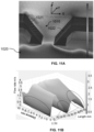
- FIG. 10A disclosure is a schematic diagram illustrating a three-dimensional flow field distribution at parallel incoming flow directions according to some embodiments of the present disclosure.
- FIG. 10B is a schematic diagram illustrating an airflow rate distribution at parallel incoming flow directions at different locations in the depression region according to some embodiments of the present disclosure.
- the deflector structure is provided along the flow direction of the airflow, wherein the flow rate of the airflow is 10 m/s, the length direction of the deflector structure (an X direction shown in FIG. 10A ) may be the same as the flow direction of the airflow, one side of the deflector structure along the width direction (a Y direction shown in FIG. 10A ) may be in contact with a wall 1010, and the other side of the deflector structure along the width direction may be exposed to airflow environment 1020 to simulate the scenario when the user wears the wearable device.
- the Y-direction shown in FIG. 10A may be used to indicate the height direction of the deflector structure. As shown in FIG.
- the wall 1010 does not extend indefinitely, and the airflow at the wall 1010 may spill out to the airflow environment 1020 along the width direction of the concave section, causing the airflow at the depression region in the concave section, but the region near a first connecting portion 1021 and a second connecting portion 1022 in the concave section still has a low-flow rate region (i.e., a region with a relatively deep gray level in the depression region in FIG. 10A ).
- the "length (mm)" coordinate marked in FIG. 10B may indicate a length of the concave section along the length direction
- a low-flow rage region 1040 may still exist near the surface of the first connecting portion 1021, near the surface of the second connecting portion 1022, and at the bottom side of the depression region; and the closer to the wall 1010, the lower the rate of airflow.
- the surface of the second connecting portion 1022 has a maximum peak value of airflow rate, and the maximum peak value does not exceed 2 m/s.
- FIG. 11A is a schematic diagram illustrating a three-dimensional flow field distribution when the incoming flow direction is 60° according to some embodiments of the present disclosure.
- FIG. 11B is a schematic diagram illustrating an airflow rate distribution at different locations in the depression region when the incoming flow direction is 60° according to some embodiments of the present disclosure.
- the flow rate of the airflow is 10 m/s
- an angle between the length direction of the deflector structure (an X direction shown in FIG. 11A ) and the flow direction of the airflow may be 60°
- one side of the deflector structure along the width direction (a Y direction shown in FIG. 11A ) may be in contact with the wall 1010, and the other side of the deflector structure along the width direction is exposed to the airflow environment 1020 to simulate the scenario when the user wears the wearable device.
- the Y-direction shown in FIG. 11A may be used to indicate the height direction of the deflector structure. As shown in FIG.
- the wall 1010 may not extend indefinitely and the airflow at the wall 1010 may spill out to the airflow environment 1020 along the width direction of the concave section, causing the airflow at the depression region in the concave section, but a low flow rate region (i.e., the region with a relatively deep gray level in the depression region in FIG. 11A ) may still exist near the first connecting portion 1021 and the second connecting portion 1022 in the concave section.
- the "length (mm)" coordinate marked in FIG. 11B may indicate a length of the concave section along the length direction
- FIG. 11B may indicate a distance to the wall 1010, and the "rate (m/s)" coordinate marked in FIG. 11B may indicate an airflow rate at different locations of the concave section.
- a low flow rate region 1050 may exist near the surface of the first connecting portion 1021, near the surface of the second connecting portion 1022, near the bottom side of the depression region; and the closer to the wall 1010, the lower the rate of airflow.
- a maximum flow rate near the surface of the first connecting portion 1021 does not exceed 3.5 m/s.
- FIG. 12A is a schematic diagram illustrating a three-dimensional flow field distribution when the incoming flow direction is 90° according to some embodiments of the present disclosure.
- FIG. 12B is a schematic diagram illustrating an airflow rate distribution at different locations in the depression region at when the incoming flow direction is 90° according to some embodiments of the present disclosure.
- the flow rate of the airflow is 10 m/s
- the angle between the length direction of the deflector structure (an X direction shown in FIG. 12A ) and the flow direction of the airflow may be 90°
- one side of the deflector structure along the width direction (a Y direction shown in FIG. 12A ) may be in contact with the wall 1010
- the other side of the deflector structure along the width direction may be exposed to the airflow environment 1020 to simulate the scenario when the user wears the wearable device.
- the Y-direction shown in FIG. 12A may be configured to indicate the height direction of the deflector structure. As shown in FIG.
- the wall 1010 may not extend indefinitely and the airflow at the wall 1010 may spill out to the airflow environment 1020 along the width direction of the concave section, causing the airflow at the depression region in the concave section, but a low-flow rate region (i.e., the region with a relatively deep gray level in the depression region in FIG. 12A ) may still exist near the first connecting portion 1021 and the second connecting portion 1022 in the concave section.
- the "length (mm)" coordinate marked in FIG. 12B may indicate the length of the concave section along the length direction
- a low flow rate region 1210 may still exist on the surface near the first connecting portion 1021, the surface of the second connecting portion 1022, and the bottom side area of the depression region; and the closer to the wall 1010, the lower the rate of airflow.
- the concave section of the deflector structure may provide a low flow rate region with a better effect of reducing the airflow rate.
- the corresponding sound inlet hole of the first microphone may be located at the bottom side of the first connecting portion, the second connecting portion, or the depression region.
- the corresponding sound inlet hole of the first microphone may be located in the depression region in the concave section near the first side portion when the user is wearing the wearable device.
- a sound inlet hole corresponding to the first microphone may be located on the first connecting section, the second connecting portion, or the bottom side of the depression region near the first side section.
- a distance between the corresponding sound inlet hole of the first microphone and the first side section may be 0 mm - 10 mm.
- the distance between the corresponding sound inlet hole of the first microphone and the first side section may be 0.2 mm to 7 mm.
- the distance between the corresponding sound inlet hole of the first microphone and the first side section may be 0.3 mm to 5 mm.
- the distance between the corresponding sound inlet hole of the first microphone and the first side section may be 0.3 mm to 3 mm.
- the distance between the corresponding sound inlet hole of the first microphone and the first side section may be 0.5 mm to 1.5 mm.
- it is also possible to improve the quality of the sound signal captured by the first microphone by adjusting the ratio of the distance between the sound inlet hole and the first side section to the size of the concave section in its width direction.
- the ratio of the distance between the sound inlet hole and the first side section to the dimension of the concave section in its width direction may be 0.01-0.9.
- the ratio of the distance between the sound inlet hole and the first side section to the dimension of the concave section in its width direction may be 0.02-0.7.
- the ratio of the distance between the sound inlet hole and the first side section to the dimension of the concave section in its width direction may be 0.03-0.5. More preferably, the ratio of the distance between the sound inlet hole and the first side section to the dimension of the concave section in its width direction may be 0.04-0.3.
- the ratio of the distance between the sound inlet hole and the first side section to the dimension of the concave section in its width direction may be 0.05-0.2. It should be noted that the above distance between the sound inlet hole and the first side section is the distance between the inlet hole and the first side section along the width direction of the deflector structure (e.g., the Y direction in FIG. 10A ).
- the wearable device may also include a sound conduction structure for transmitting external sound
- the sound conduction structure may be connected to the concave section
- the sound conduction structure may have an internal pass through structure
- one end of the sound conduction structure may be connected to the external environment
- the first microphone may be located at the other end of the sound conduction structure.
- the sound conduction structure may be a separate component relative to the concave section.
- a cavity for the sound conduction structure is opened in the side wall corresponding to the depression region of the concave section, and the sound conduction structure is located in the cavity.
- the sound conduction structure and the concave section may be an integral part.
- the sound conduction structure may be a sound conduction cavity opened in the side wall corresponding to the depression region of the concave section.
- FIG. 13 is a schematic diagram illustrating a structure of a sound conduction structure according to some embodiments of the present disclosure.
- the sound conduction structure 1300 may be an internal passthrough structure, and the sound conduction structure 1300 may be provided with a plurality of sound conduction channels inside, and the plurality of sound conduction channels may be obliquely connected in sequence.
- the sound conduction channel located at the top of the sound conduction structure 1300 may be connected to the external environment, and the first microphone may be located at the sound conduction channel at the bottom side of the sound conduction structure 1300.
- the airflow When the external airflow enters the sound conduction structure 1300, the airflow may form a vortex when it meets the bending connection of the two sound conduction channels, the kinetic energy of the airflow is consumed at this time, and when the airflow reaches the first microphone, the rate of the airflow may be greatly reduced, thus further reducing the impact of the external airflow on the sound signal collected by the first microphone.
- the shape of the sound conduction channel 1310 may be cylindrical, polygonal (e.g., rectangular, trigonal), trapezoidal, or other regular shapes.
- the sound conduction channel 1310 may also be non-regularly shaped, for example, horn-shaped.
- a bending angle of each sound conduction channel in the sound conduction structure 1300 is set within a specific range of angles.
- the bending angles of the sound conduction channels in the sound conduction structure 1300 may be in a range of 65°-135°.
- the bending angle of each sound conduction channel in the sound conduction structure 1300 may be in a range of 70°-120°.
- the bending angle of each sound conduction channel in the sound conduction structure 1300 may be in a range of 85°-95°. More preferably, the bending angle of each sound conduction channel in the sound conduction structure 1300 may be 90°.
- the bending angles of different sound conduction channels may be the same or different, and the bending angle of each sound conduction channel in the sound conduction structure 1300 is not limited to the above range, but may also be greater than 135° or less than 65°.
- the cross-sectional shape of the sound conduction channel may be polygonal (e.g., triangular, quadrilateral, pentagonal, etc.), circular, semicircular, elliptical, semi-elliptical, and other shapes.
- the dimensions of the different locations of the sound conduction channels may be the same or different.
- the sound conduction channel may be a cylindrical channel, where the radius of each location of the sound conduction channel is the same.
- the sound conduction channel may be horn-shaped, in which case the radius of the channel increases or decreases gradually.
- the shapes of the plurality of sound conduction channels may be the same or different.
- the bending portion between different sound conduction channels may be chamfered so that the airflow can create turbulence at the bend.
- the total length of the sound conduction channels in the sound conduction structure 1300 may be adjusted to ensure the wind noise reduction effect of the sound conduction structure.
- the total length of the sound conduction channels may be greater than 10 mm.
- the total length of the sound conduction channels may be greater than 13 mm.
- the total length of the sound conduction channels may be greater than 17 mm.
- the total length of the sound conduction channels may be greater than 20 mm.
- the total length of the sound conduction channels may be 20.4 mm.
- the wind noise reduction effect of the sound conduction structure may also be ensured by adjusting the count of bends between the sound conduction channels in the sound conduction structure 1300.
- the count of bends between the sound conduction channels may be greater than five.
- the count of bends between the sound conduction channels may be greater than eight.
- the count of bends between the sound conduction channels may be greater than 10.
- FIG. 14 is a schematic diagram illustrating a structure of a sound conduction structure according to some embodiments of the present disclosure.
- the sound conduction structure 1400 may include a cavity 1410, which is connected to the external through a connecting hole 1420.
- the count of cavities 1410 may be more than one, and the plurality of cavities 1410 may be located at intervals along the length of the sound conduction structure 1400, wherein the adjacent cavities 1410 may also be connected to each other by a connecting hole 1420.
- the size of a cavity 1410 along the width of the sound conduction structure 1400 is larger than the size of a connecting hole 1420 along the width of the sound conduction structure 1400.
- the airflow may form a vortex system structure after encountering the connection between the connecting hole 1420 and the cavity 1410 due to the sudden change in volume, which causes the kinetic energy of the airflow to be consumed, and when the airflow reaches the first microphone, the rate of the airflow is greatly reduced, thus further reducing the effect of the external airflow on the sound signal collected by the first microphone.
- the dimensions (e.g., length, width, volume, or surface area) of a cavity or a connecting hole may be adjusted to ensure the wind noise reduction of the sound conduction structure.
- the volume of a single cavity 1410 may be greater than 4 mm 3 .
- the volume of a single cavity 1410 may be greater than 10 mm 3 .
- the volume of a single cavity 1410 may be greater than 20 mm 3 .
- the volume of a single cavity 1410 may be greater than 30 mm 3 .
- the volume of a single cavity 1410 may be greater than 40 mm 3 .
- the volume of a single cavity 1410 may be 40 mm 3 .
- the surface area corresponding to a single cavity 1410 may be greater than 12 mm 2 .
- the surface area corresponding to a single cavity 1410 may be greater than 30 mm 2 . More preferably, the surface area corresponding to a single cavity 1410 may be greater than 60 mm 2 . More preferably, the surface area corresponding to a single cavity 1410 may be greater than 70 mm 2 .
- the surface area corresponding to a single cavity 1410 may be 72 mm 2 .
- the diameter of a connecting hole 1420 may be 0.2 mm-2 mm, and the length of the connecting hole 1420 may be less than 5 mm.
- the diameter of a connecting hole 1420 may be 0.4 mm-1.8 mm, and the length of the connecting hole 1420 may be less than 3 mm.
- the diameter of a connecting hole 1420 may be 1.1 mm and the length of the connecting hole 1420 may be 2 mm.
- the cross-sectional shape of a cavity 1410 may be polygonal (e.g., triangular, quadrilateral, pentagonal, etc.), circular, semicircular, elliptical, semi-elliptical, and other shapes.
- the sound conduction structure 1300 shown in FIG. 13 and the sound conduction structure 1400 shown in FIG. 14 can be installed in any microphone other than the first microphone, for example, the second microphone may also be provided with the sound conduction structure 1300 or the sound conduction structure 1400.
- the sound conduction structure may also be a combination of the sound conduction structure 1300 shown in FIG. 13 and the sound conduction structure 1400 shown in FIG. 14 .
- the ends or internals of a sound conduction structure e.g., the sound conduction structure 1300 and the sound conduction structure 1400
- the mesh structure prevents dust and particles in the outside world from entering the microphone.
- the wearable device may include a first microphone and a second microphone, wherein when the user wears the wearable device, the connection line of the first microphone and the second microphone is in the direction of the mouth of the user, and the distance between the first microphone and the mouth of the user is smaller than the distance between the second microphone and the mouth of the human body.
- the first microphone may primarily be used to pick up the sound signal when the user is speaking
- the second microphone may also pick up the sound signal when the user is speaking
- the processor of the wearable device may determine the sound signal when the user is speaking among the sound signals picked up by the first microphone and the second microphone through an algorithm, so that other sound signals (e.g., wind noise) can be filtered and processed.
- the distance between the first microphone and the second microphone may be 5 mm-70 mm.
- the distance between the first microphone and the second microphone may be 10 mm to 50 mm.
- the distance between the first microphone and the second microphone may be 25 mm-30 mm.
- the vibration direction of the diaphragm in the first microphone may be substantially perpendicular to the vibration direction of the diaphragm in the second microphone.
- the substantially perpendicular means that the vibration direction of the diaphragm in the first microphone may be 90° to the vibration direction of the diaphragm in the second microphone, or an angle close to 90°, such as 75°, 80°, 95°, 100°, etc. As shown in FIG.
- a first sound inlet hole 153 corresponding to the first microphone may be located at the side wall corresponding to the depression region in a concave section 1512.
- the first sound inlet hole 153 corresponding to the first microphone may be located at the first connecting portion or the second connecting portion of the concave section 1512, or the connection between the two connecting portions.
- the vibration direction of the diaphragm of the first microphone is set perpendicular or approximately perpendicular to the vibration direction of the diaphragm of the second microphone, and the wind noise picked up by the microphone (e.g., the first microphone and the second microphone) may be further cancelled by an algorithm based on the correlation of the wind noises.
- a second sound inlet hole 154 corresponding to the second microphone may be located at the second connecting section 1513 such that when the user wears the wearable device, a line connecting the first sound inlet hole 153 corresponding to the first microphone and the second sound inlet hole 154 corresponding to the second microphone directs toward the mouth of the user.
- the second sound inlet hole 154 may also be located at the concave section 1512.
- the second sound inlet hole 154 is located on the side of the second connecting portion of the concave section 1512 away from the first sound inlet hole 153.
- the second sound inlet hole 154 may also be located at the side wall of the second connecting portion corresponding to the depression region of the concave section 1512.
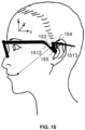
- a three-dimensional coordinate system is established with any point of the head of the user as the origin, wherein the x-axis in the three-dimensional coordinate system is parallel to the horizontal plane, the z-axis is perpendicular to the horizontal plane, and the y-axis is perpendicular to the x-axis and z-axis.
- the length direction of the sound conduction structure may be regarded as the x-axis direction
- the height direction of the sound conduction structure may be regarded as the z-axis direction
- the width direction of the sound conduction structure may be regarded as the y-axis direction.
- the length direction, width direction, or height direction of the sound conduction structure shown in each of the above accompanying figures may refer to the scenario in FIG. 15 when a user is wearing a wearable device.
- the wearable device may also include an acoustic output unit 155, and the acoustic output unit 155 may be located at the concave section 1512. In some embodiments, the acoustic output unit 155 may be located on the external surface of the concave section 1512. For example, when the acoustic output unit 155 is a bone conduction speaker, the acoustic output unit 155 may be located on the side of the concave section 1512 that is in contact with the user. As another example, when the acoustic output unit 155 is an air conduction speaker, the acoustic output unit 155 may be located on the side of the concave section 1512 that is not in contact with the user.
- the acoustic output unit 155 may be located inside the concave section 1512.
- the concave section 1512 has an accommodation cavity (not shown in FIG. 15 ), and the acoustic output unit 155 may be located in this accommodation cavity.
- the concave section 1512 may serve as a housing for the acoustic output unit 155, and other components of the acoustic output unit 155 (e.g., a magnetic circuit structure, a diaphragm, etc.) may be located in the concave section 1512.
- the acoustic output unit 155 may include a diaphragm and a magnetic circuit structure (not shown in FIG. 15 ), the diaphragm is connected to a voice coil, the voice coil extends into a magnetic gap of the magnetic circuit structure, the magnetic circuit structure is connected to the housing of the acoustic output unit 155 (or the concave section 1512).
- the side of the diaphragm facing the magnetic circuit structure forms the front of the acoustic output unit 155, the side of the magnetic circuit structure facing the diaphragm forms the back of the acoustic output unit 155, and the diaphragm vibrates so that the acoustic output unit radiates sound outward from its front and back, respectively.
- the housing of the acoustic output unit 155 may include at least two sound conduction holes (not shown in FIG. 15 ), which may include a first sound conduction hole (also referred to as a sound outlet hole) and a second sound conduction hole (also referred to as a pressure relief hole).
- a first sound conduction hole also referred to as a sound outlet hole
- a second sound conduction hole also referred to as a pressure relief hole
- the first sound conduction hole may be used to output sound from the front of the acoustic output unit 155
- the second sound conduction hole may be used to output sound from the back of the acoustic output unit 155
- the phase of the sound output from the first sound conduction hole and the phase of the sound output from the second sound conduction hole may be considered opposite so that the sound output from the first sound conduction hole and the sound output from the second sound conduction hole may form a dipole.
- the count of first sound conduction holes and second sound conduction holes may be one or more. In some embodiments, the number, size, location, acoustic resistance, and other parameters of the first or second sound conduction hole may be adjusted to further improve the listening effect and sound leakage reduction effect of the wearable device.
- the first microphone plays the main sound pickup function in picking up the sound signal when the user is speaking.
- the vibration direction of the diaphragm of the first microphone is perpendicular or substantially perpendicular to the vibration direction of the diaphragm of the acoustic output unit.
- the first microphone and/or the second microphone may be located in the area least affected by the acoustic output unit, such as the acoustic zero region of the acoustic output unit.
- FIG. 16 and 17 are schematic diagrams illustrating a sound field radiation of an acoustic output unit according to some embodiments of the present disclosure, wherein FIG. 17 shows the sound field radiation diagram from the viewpoint indicated by the arrow M in FIG. 16 .
- the acoustic zero region of the acoustic output unit 1601 is the darker colored region in the figures (i.e., a region 1610).
- the housing of the acoustic output unit 1601 may include at least two sound conduction holes, which may include a first sound conduction hole 1602 (also referred to as a sound outlet hole) and a second sound conduction hole 1603 (also referred to as a pressure relief hole), the first sound conduction hole 1602 may be configured to output sound from the front of the acoustic output unit 1601, and the second sound conduction hole 1603 may be configured to output sound from the back of the acoustic output unit 1601.
- a first sound conduction hole 1602 also referred to as a sound outlet hole
- a second sound conduction hole 1603 also referred to as a pressure relief hole
- the phase of the sound output from the first sound conduction hole 1602 and the phase of the sound output from the second sound conduction hole 1603 may be considered opposite, such that the sound output from the first sound conduction hole 1602 and the sound output from the second sound conduction hole 1603 may construct an acoustic dipole and form an acoustic zero region 1610.
- the location of the first microphone and the second microphone may be selected and determined based on the acoustic zero region of the acoustic output unit.
- beneficial effects may be any one or combination of the above or any other beneficial effects that may be obtained.
Landscapes
- Physics & Mathematics (AREA)
- Acoustics & Sound (AREA)
- Engineering & Computer Science (AREA)
- Signal Processing (AREA)
- Health & Medical Sciences (AREA)
- Otolaryngology (AREA)
- General Physics & Mathematics (AREA)
- Optics & Photonics (AREA)
- General Health & Medical Sciences (AREA)
- Ophthalmology & Optometry (AREA)
- Details Of Audible-Bandwidth Transducers (AREA)
- Circuit For Audible Band Transducer (AREA)
- Telephone Set Structure (AREA)
Claims (15)
- Tragbare Vorrichtung (100, 200, 300), umfassend:eine Deflektorstruktur (110, 210, 310, 410, 610), die dazu konfiguriert ist, auf einem Kopf eines Benutzers getragen zu werden, wobei die Deflektorstruktur (110, 210, 310, 410, 610) Folgendes beinhaltet:einen ersten Verbindungsabschnitt (211, 311, 611, 811), einen zweiten Verbindungsabschnitt (213, 613, 1513) und einen konkaven Abschnitt (212, 312, 612, 712, 812, 1512), wobei der erste Verbindungsabschnitt (211, 311, 611, 811), der konkave Abschnitt (212, 312, 612, 712, 812, 1512) und der zweite Verbindungsabschnitt (213, 613, 1513) hintereinander verbunden sind und der konkave Abschnitt (212, 312, 612, 712, 812, 1512) im Verhältnis zur Deflektorstruktur (110, 210, 310, 410, 610) einen nach unten gerichteten Vertiefungsbereich aufweist;ein erstes Mikrofon (230, 330), das zum Aufnehmen eines Schallsignals konfiguriert ist, wobei sich das erste Mikrofon (230, 330) am konkaven Abschnitt (212, 312, 612, 712, 812, 1512) befindet;dadurch gekennzeichnet, dass sie weiter umfasst:
eine Schallleitungsstruktur (1300, 1400), die zum Übertragen von äußerem Schall konfiguriert ist, wobei die Schallleitungsstruktur (1300, 1400) mit dem konkaven Abschnitt (212, 312, 612, 712, 812, 1512) verbunden ist, die Schallleitungsstruktur (1300, 1400) eine interne Durchgangsstruktur ist, ein Ende der Schallleitungsstruktur (1300, 1400) mit der äußeren Umgebung verbunden ist und sich das erste Mikrofon (230, 330) an einem anderen Ende der Schallleitungsstruktur (1300, 1400) befindet. - Tragbare Vorrichtung (100, 200, 300) nach Anspruch 1, wobei sich das erste Mikrofon (230, 330) an einer Unterseite des nach unten gerichteten Vertiefungsbereichs im konkaven Abschnitt (212, 312, 612, 712, 812, 1512) befindet.
- Tragbare Vorrichtung (100, 200, 300) nach Anspruch 1 oder 2, wobei der erste Verbindungsabschnitt (211, 311, 611, 811) einen ersten Endteilabschnitt (6111, 7111) und einen zweiten Endteilabschnitt (6112, 7112, 8112) beinhaltet, der zweite Endteilabschnitt (6112, 7112, 8112) mit dem konkaven Abschnitt (212, 312, 612, 712, 812, 1512) verbunden ist, eine Höhe des ersten Endteilabschnitts (6111, 7111) im Verhältnis zu einem Boden des konkaven Abschnitts (212, 312, 612, 712, 812, 1512) nicht größer ist als eine Höhe des zweiten Endteilabschnitts (6112, 7112, 8112) im Verhältnis zu dem Boden des konkaven Abschnitts (212, 312, 612, 712, 812, 1512).
- Tragbare Vorrichtung (100, 200, 300) nach Anspruch 3, wobei der zweite Verbindungsabschnitt (213, 613, 1513) einen dritten Endteilabschnitt (6131, 7131) und einen vierten Endteilabschnitt (6132, 7132) beinhaltet, der dritte Endteilabschnitt (6131, 7131) mit dem konkaven Abschnitt (212, 312, 612, 712, 812, 1512) verbunden ist, eine Höhe des dritten Endteilabschnitts (6131, 7131) im Verhältnis zum Boden des konkaven Abschnitts (212, 312, 612, 712, 812, 1512) nicht geringer ist als eine Höhe des vierten Endteilabschnitts (6132, 7132) im Verhältnis zum Boden des konkaven Abschnitts (212, 312, 612, 712, 812, 1512).
- Tragbare Vorrichtung (100, 200, 300) nach Anspruch 4, wobei die Höhe des zweiten Endteilabschnitts (6112, 7112, 8112) im Verhältnis zum Boden des konkaven Abschnitts (212, 312, 612, 712, 812, 1512) nicht geringer ist als die Höhe des dritten Endteilabschnitts (6131, 7131) im Verhältnis zum Boden des konkaven Abschnitts (212, 312, 612, 712, 812, 1512).
- Tragbare Vorrichtung (100, 200, 300) nach einem der Ansprüche 1-5, wobei der konkave Abschnitt (212, 312, 612, 712, 812, 1512) einen ersten Verbindungsteilabschnitt (6121, 1021) und einen zweiten Verbindungsteilabschnitt (6122, 1022) beinhaltet, wobei der erste Verbindungsteilabschnitt (6121, 1021) schräg mit dem ersten Verbindungsabschnitt (211, 311, 611, 811) verbunden ist und sich nach unten erstreckt, der zweite Verbindungsteilabschnitt (6122, 1022) schräg mit dem zweiten Verbindungsabschnitt (213, 613, 1513) verbunden ist und sich nach unten erstreckt, wobei ein Ende des ersten Verbindungsteilabschnitts (6121, 1021) entfernt vom ersten Verbindungsabschnitt (211, 311, 611, 811) mit einem Ende des zweiten Verbindungsteilabschnitts (6122, 1022) entfernt vom zweiten Verbindungsabschnitt (213, 613, 1513) verbunden ist.
- Tragbare Vorrichtung (100, 200, 300) nach Anspruch 6, wobei ein Abstand zwischen dem ersten Verbindungsteilabschnitt (6121, 1021) und dem zweiten Verbindungsteilabschnitt (6122, 1022) entlang einer vertieften Richtung des konkaven Abschnitts (212, 312, 612, 712, 812, 1512) allmählich abnimmt.
- Tragbare Vorrichtung (100, 200, 300) nach Anspruch 1, wobei innerhalb der Schallleitungsstruktur (1300, 1400) eine Vielzahl von Schallleitungskanälen angeordnet sind und die Vielzahl von Schallleitungskanälen schräg hintereinander verbunden sind.
- Tragbare Vorrichtung (100, 200, 300) nach Anspruch 8, wobei die Schallleitungsstruktur (1300, 1400) eine Vielzahl von Hohlräumen (1410) beinhaltet, die Vielzahl von Hohlräumen (1410) in Intervallen entlang einer Längsrichtung der Schallleitungsstruktur (1300, 1400) verteilt ist, benachbarte Hohlräume (1410) durch ein Verbindungsloch (1420) miteinander verbunden sind;
eine Abmessung des Hohlraums (1410) entlang einer Breitenrichtung der Schallleitungsstruktur (1300, 1400) größer ist als eine Abmessung des Verbindungslochs (1420) entlang der Breitenrichtung der Schallleitungsstruktur (1300, 1400). - Tragbare Vorrichtung (100, 200, 300) nach einem der Ansprüche 1-9, wobei der zweite Verbindungsabschnitt (213, 613, 1513) mit einem zweiten Mikrofon (623) versehen ist.
- Tragbare Vorrichtung (100, 200, 300) nach Anspruch 10, wobei das erste Mikrofon (230, 330) und das zweite Mikrofon (623) so konfiguriert sind, dass, wenn die tragbare Vorrichtung (100, 200, 300) von dem Benutzer getragen wird, eine Verbindungsleitung zwischen dem ersten Mikrofon (230, 330) und dem zweiten Mikrofon (623) in Richtung des Mundes des Benutzers zeigt.
- Tragbare Vorrichtung (100, 200, 300) nach Anspruch 10 oder 11, wobei eine Schwingungsrichtung einer Membran im ersten Mikrofon (230, 330) im Wesentlichen senkrecht zu einer Schwingungsrichtung einer Membran im zweiten Mikrofon (623) ist.
- Tragbare Vorrichtung (100, 200, 300) nach einem der Ansprüche 10-12, wobei ein Abstand zwischen dem ersten Mikrofon (230, 330) und dem zweiten Mikrofon (623) 5 mm-70 mm beträgt.
- Tragbare Vorrichtung (100, 200, 300) nach einem der Ansprüche 1-13, wobei die Deflektorstruktur (110, 210, 310, 410, 610) eine erste Deflektorstruktur und eine zweite Deflektorstruktur beinhaltet, wobei die erste Deflektorstruktur und die zweite Deflektorstruktur am linken bzw. am rechten Ohr des Benutzers angebracht sind.
- Tragbare Vorrichtung (100, 200, 300) nach Anspruch 14, wobei die tragbare Vorrichtung (100, 200, 300) weiter eine akustische Ausgabeeinheit (155, 1601) beinhaltet, wobei sich die akustische Ausgabeeinheit (155, 1601) am konkaven Abschnitt (212, 312, 612, 712, 812, 1512) befindet.
Applications Claiming Priority (1)
| Application Number | Priority Date | Filing Date | Title |
|---|---|---|---|
| PCT/CN2022/072151 WO2023133846A1 (zh) | 2022-01-14 | 2022-01-14 | 一种可穿戴设备 |
Publications (4)
| Publication Number | Publication Date |
|---|---|
| EP4243441A1 EP4243441A1 (de) | 2023-09-13 |
| EP4243441A4 EP4243441A4 (de) | 2023-10-25 |
| EP4243441B1 true EP4243441B1 (de) | 2025-05-14 |
| EP4243441C0 EP4243441C0 (de) | 2025-05-14 |
Family
ID=83176452
Family Applications (2)
| Application Number | Title | Priority Date | Filing Date |
|---|---|---|---|
| EP22822843.3A Active EP4243441B1 (de) | 2022-01-14 | 2022-01-14 | Tragbare vorrichtungen |
| EP22920014.2A Pending EP4279984A4 (de) | 2022-01-14 | 2022-12-14 | Wearable-vorrichtung und trageelement dafür |
Family Applications After (1)
| Application Number | Title | Priority Date | Filing Date |
|---|---|---|---|
| EP22920014.2A Pending EP4279984A4 (de) | 2022-01-14 | 2022-12-14 | Wearable-vorrichtung und trageelement dafür |
Country Status (6)
| Country | Link |
|---|---|
| US (3) | US12449678B2 (de) |
| EP (2) | EP4243441B1 (de) |
| JP (2) | JP7500865B2 (de) |
| KR (2) | KR102689176B1 (de) |
| CN (6) | CN116762361A (de) |
| WO (2) | WO2023133846A1 (de) |
Families Citing this family (5)
| Publication number | Priority date | Publication date | Assignee | Title |
|---|---|---|---|---|
| JP7479713B2 (ja) * | 2022-01-13 | 2024-05-09 | 株式会社エスケイワイ | 眼鏡 |
| JP7500865B2 (ja) * | 2022-01-14 | 2024-06-17 | シェンツェン・ショックス・カンパニー・リミテッド | ウェアラブル装置 |
| CN117255278B (zh) * | 2023-03-23 | 2024-10-11 | 荣耀终端有限公司 | 电子设备 |
| CN116684782A (zh) * | 2023-05-11 | 2023-09-01 | 湖北星纪魅族科技有限公司 | 音腔结构及可穿戴设备 |
| WO2024250283A1 (zh) * | 2023-06-09 | 2024-12-12 | 瑞声科技(南京)有限公司 | 减小漏音的智能设备、方法、系统及计算机设备 |
Family Cites Families (47)
| Publication number | Priority date | Publication date | Assignee | Title |
|---|---|---|---|---|
| US2952748A (en) * | 1955-06-21 | 1960-09-13 | Beltone Hearing Aid Company | Binaural eyeglass hearing aid construction |
| JP2548062Y2 (ja) * | 1991-08-23 | 1997-09-17 | 三菱電機株式会社 | 送話器構造 |
| US6091832A (en) | 1996-08-12 | 2000-07-18 | Interval Research Corporation | Wearable personal audio loop apparatus |
| US6176576B1 (en) * | 1997-06-06 | 2001-01-23 | Radians, Inc. | Eyewear supported by a wearer's concha of an ear |
| US7013009B2 (en) | 2001-06-21 | 2006-03-14 | Oakley, Inc. | Eyeglasses with wireless communication features |
| US7313246B2 (en) * | 2001-10-06 | 2007-12-25 | Stryker Corporation | Information system using eyewear for communication |
| US6729726B2 (en) * | 2001-10-06 | 2004-05-04 | Stryker Corporation | Eyewear for hands-free communication |
| US7500746B1 (en) * | 2004-04-15 | 2009-03-10 | Ip Venture, Inc. | Eyewear with radiation detection system |
| US20080008344A1 (en) * | 2004-09-07 | 2008-01-10 | Tetsuo Wakabayashi | Spectacle Type Communication Device |
| RU46619U1 (ru) | 2005-03-09 | 2005-07-10 | Открытое Акционерное Общество "ОКБ "Октава" | Телефонно-микрофонная гарнитура |
| KR101492751B1 (ko) * | 2010-08-27 | 2015-02-11 | 노키아 코포레이션 | 원치 않는 사운드들을 제거하는 마이크로폰 장치 및 방법 |
| EP2600634B1 (de) * | 2011-12-02 | 2015-04-29 | GN Netcom A/S | Mikrofonschlitze zur Reduzierung des Windrauschens |
| CN203720476U (zh) * | 2013-11-08 | 2014-07-16 | 深圳市广百思科技有限公司 | 一种蓝牙太阳镜 |
| WO2020220724A1 (zh) | 2019-04-30 | 2020-11-05 | 深圳市韶音科技有限公司 | 一种声学输出装置 |
| US11156855B2 (en) * | 2016-05-09 | 2021-10-26 | Oakley, Inc. | Modular wearable electronic devices, systems, and methods |
| US10631073B2 (en) * | 2016-06-16 | 2020-04-21 | Intel Corporation | Microphone housing with screen for wind noise reduction |
| US9881600B1 (en) * | 2016-07-29 | 2018-01-30 | Bose Corporation | Acoustically open headphone with active noise reduction |
| CN106226920A (zh) * | 2016-08-19 | 2016-12-14 | 赵矗 | 多功能智能眼镜 |
| JP6315046B2 (ja) | 2016-09-14 | 2018-04-25 | ソニー株式会社 | 耳孔装着型収音装置、信号処理装置、収音方法 |
| CN109923872A (zh) * | 2016-10-28 | 2019-06-21 | 松下知识产权经营株式会社 | 声音输入输出装置及骨传导头戴式耳机系统 |
| CN107426643B (zh) | 2017-07-31 | 2019-08-23 | 歌尔股份有限公司 | 上行降噪耳机 |
| EP3445066B1 (de) * | 2017-08-18 | 2021-06-16 | Facebook Technologies, LLC | Knorpelleiteraudiosystem für brillenvorrichtungen |
| US10757501B2 (en) * | 2018-05-01 | 2020-08-25 | Facebook Technologies, Llc | Hybrid audio system for eyewear devices |
| WO2020038475A1 (zh) | 2018-08-24 | 2020-02-27 | 深圳市韶音科技有限公司 | 一种扬声器 |
| CN209233982U (zh) * | 2018-12-10 | 2019-08-09 | 佳禾智能科技股份有限公司 | 一种通过多孔对消的扰动气流消除结构 |
| WO2020140456A1 (zh) * | 2019-01-05 | 2020-07-09 | 深圳市韶音科技有限公司 | 一种扬声器装置 |
| CN110113687B (zh) * | 2019-04-12 | 2024-10-01 | 苏州敏芯微电子技术股份有限公司 | 硅麦克风 |
| CN114222601A (zh) * | 2019-05-07 | 2022-03-22 | 科罗拉多州立大学董事会法人团体 | 用于耳后感测和刺激的可穿戴系统 |
| US11197083B2 (en) * | 2019-08-07 | 2021-12-07 | Bose Corporation | Active noise reduction in open ear directional acoustic devices |
| CN110568633A (zh) | 2019-08-14 | 2019-12-13 | 歌尔股份有限公司 | 一种智能头戴设备 |
| CN210183483U (zh) * | 2019-08-14 | 2020-03-24 | 歌尔科技有限公司 | 一种智能头戴设备 |
| US11223889B2 (en) * | 2019-12-16 | 2022-01-11 | Bose Corporation | Audio device with vibrationally isolated transducer |
| CN110856076A (zh) | 2019-12-25 | 2020-02-28 | 歌尔科技有限公司 | 一种防风噪耳机 |
| CN211152175U (zh) * | 2020-02-26 | 2020-07-31 | 深圳市魔浪电子有限公司 | 一种后挂式耳机 |
| CN212034322U (zh) * | 2020-04-20 | 2020-11-27 | 深圳市博朗声学科技有限公司 | 一种降噪耳机 |
| TWM601351U (zh) | 2020-05-07 | 2020-09-11 | 陳志春 | 眼鏡的智能結構 |
| CN212649672U (zh) | 2020-06-10 | 2021-03-02 | 深圳市冠旭电子股份有限公司 | 蓝牙耳机 |
| CN111562676A (zh) * | 2020-06-24 | 2020-08-21 | 歌尔科技有限公司 | 一种眼镜 |
| CN213485164U (zh) * | 2020-08-12 | 2021-06-18 | 深圳市韶音科技有限公司 | 一种发声装置 |
| CN213547788U (zh) * | 2020-08-31 | 2021-06-25 | 深圳市冠旭电子股份有限公司 | 耳机头以及头戴式耳机 |
| CN214045934U (zh) * | 2020-11-15 | 2021-08-24 | 深圳市大十科技有限公司 | 一种蓝牙音频装置及悬挂式蓝牙耳机 |
| CN215932289U (zh) * | 2021-03-26 | 2022-03-01 | 深圳市韶音科技有限公司 | 眼镜 |
| CN214704204U (zh) * | 2021-02-01 | 2021-11-12 | 深圳市韶音科技有限公司 | 眼镜及其镜腿 |
| EP4177668A4 (de) * | 2020-11-26 | 2024-03-27 | Shenzhen Shokz Co., Ltd. | Tragbare vorrichtung |
| CN113395619A (zh) | 2021-06-07 | 2021-09-14 | 佳禾智能科技股份有限公司 | 一种防风噪麦克风及电子设备 |
| CN113891213B (zh) * | 2021-10-26 | 2023-11-03 | 苏州登堡电子科技有限公司 | 一种优化骨传导耳机 |
| JP7500865B2 (ja) * | 2022-01-14 | 2024-06-17 | シェンツェン・ショックス・カンパニー・リミテッド | ウェアラブル装置 |
-
2022
- 2022-01-14 JP JP2023509424A patent/JP7500865B2/ja active Active
- 2022-01-14 WO PCT/CN2022/072151 patent/WO2023133846A1/zh not_active Ceased
- 2022-01-14 CN CN202280005036.1A patent/CN116762361A/zh active Pending
- 2022-01-14 KR KR1020237002156A patent/KR102689176B1/ko active Active
- 2022-01-14 EP EP22822843.3A patent/EP4243441B1/de active Active
- 2022-01-27 CN CN202220233972.5U patent/CN217428213U/zh active Active
- 2022-01-27 CN CN202210101579.5A patent/CN116489277A/zh active Pending
- 2022-01-27 CN CN202220235657.6U patent/CN217428214U/zh active Active
- 2022-01-27 CN CN202210101580.8A patent/CN116489278A/zh active Pending
- 2022-12-14 CN CN202280007748.7A patent/CN117441125A/zh active Pending
- 2022-12-14 KR KR1020237032567A patent/KR20230146091A/ko active Pending
- 2022-12-14 WO PCT/CN2022/139086 patent/WO2023134382A1/zh not_active Ceased
- 2022-12-14 JP JP2023558275A patent/JP7657495B2/ja active Active
- 2022-12-14 EP EP22920014.2A patent/EP4279984A4/de active Pending
- 2022-12-16 US US18/067,660 patent/US12449678B2/en active Active
-
2023
- 2023-08-15 US US18/450,389 patent/US12449679B2/en active Active
-
2025
- 2025-10-20 US US19/363,600 patent/US20260044024A1/en active Pending
Also Published As
| Publication number | Publication date |
|---|---|
| EP4279984A4 (de) | 2024-08-07 |
| US12449678B2 (en) | 2025-10-21 |
| CN116762361A (zh) | 2023-09-15 |
| JP7500865B2 (ja) | 2024-06-17 |
| KR20230110480A (ko) | 2023-07-24 |
| WO2023134382A1 (zh) | 2023-07-20 |
| CN117441125A (zh) | 2024-01-23 |
| WO2023133846A1 (zh) | 2023-07-20 |
| US20230229025A1 (en) | 2023-07-20 |
| EP4243441A4 (de) | 2023-10-25 |
| EP4243441C0 (de) | 2025-05-14 |
| JP2024512948A (ja) | 2024-03-21 |
| EP4279984A1 (de) | 2023-11-22 |
| US12449679B2 (en) | 2025-10-21 |
| EP4243441A1 (de) | 2023-09-13 |
| CN217428213U (zh) | 2022-09-13 |
| KR20230146091A (ko) | 2023-10-18 |
| CN217428214U (zh) | 2022-09-13 |
| JP7657495B2 (ja) | 2025-04-07 |
| US20260044024A1 (en) | 2026-02-12 |
| US20230388689A1 (en) | 2023-11-30 |
| CN116489278A (zh) | 2023-07-25 |
| CN116489277A (zh) | 2023-07-25 |
| JP2024507307A (ja) | 2024-02-19 |
| KR102689176B1 (ko) | 2024-07-30 |
Similar Documents
| Publication | Publication Date | Title |
|---|---|---|
| EP4243441B1 (de) | Tragbare vorrichtungen | |
| US12225347B2 (en) | Sound-producing device | |
| US12386209B2 (en) | Eyeglasses | |
| US11979701B1 (en) | Open earphones | |
| WO2024087442A1 (zh) | 一种开放式耳机 | |
| RU2815093C1 (ru) | Носимые устройства | |
| TWI842238B (zh) | 可穿戴設備 | |
| HK40090140A (zh) | 一种可穿戴设备 | |
| CN117793588A (zh) | 一种声学输出装置 | |
| RU2800544C1 (ru) | Звукопроизводящее устройство | |
| US20240284087A1 (en) | Acoustic output devices | |
| CN223639366U (zh) | 耳夹式耳机及其充电舱、充电系统 | |
| US12520437B2 (en) | Wearing members, wearing devices, and charging systems | |
| US20260046555A1 (en) | Acoustic output devices | |
| CN117321479A (zh) | 可穿戴设备及其佩戴件 | |
| CN119835560A (zh) | 耳夹式耳机及其充电舱、充电系统 | |
| HK40072564A (en) | Sound producing device | |
| CN120166336A (zh) | 一种声学输出装置 |
Legal Events
| Date | Code | Title | Description |
|---|---|---|---|
| STAA | Information on the status of an ep patent application or granted ep patent |
Free format text: STATUS: UNKNOWN |
|
| STAA | Information on the status of an ep patent application or granted ep patent |
Free format text: STATUS: THE INTERNATIONAL PUBLICATION HAS BEEN MADE |
|
| PUAI | Public reference made under article 153(3) epc to a published international application that has entered the european phase |
Free format text: ORIGINAL CODE: 0009012 |
|
| STAA | Information on the status of an ep patent application or granted ep patent |
Free format text: STATUS: REQUEST FOR EXAMINATION WAS MADE |
|
| 17P | Request for examination filed |
Effective date: 20221222 |
|
| AK | Designated contracting states |
Kind code of ref document: A1 Designated state(s): AL AT BE BG CH CY CZ DE DK EE ES FI FR GB GR HR HU IE IS IT LI LT LU LV MC MK MT NL NO PL PT RO RS SE SI SK SM TR |
|
| A4 | Supplementary search report drawn up and despatched |
Effective date: 20230925 |
|
| RIC1 | Information provided on ipc code assigned before grant |
Ipc: H04R 1/08 20060101ALI20230919BHEP Ipc: H04R 1/10 20060101AFI20230919BHEP |
|
| GRAP | Despatch of communication of intention to grant a patent |
Free format text: ORIGINAL CODE: EPIDOSNIGR1 |
|
| STAA | Information on the status of an ep patent application or granted ep patent |
Free format text: STATUS: GRANT OF PATENT IS INTENDED |
|
| RIC1 | Information provided on ipc code assigned before grant |
Ipc: H04R 1/08 20060101ALI20250130BHEP Ipc: H04R 1/10 20060101AFI20250130BHEP |
|
| INTG | Intention to grant announced |
Effective date: 20250219 |
|
| GRAS | Grant fee paid |
Free format text: ORIGINAL CODE: EPIDOSNIGR3 |
|
| GRAA | (expected) grant |
Free format text: ORIGINAL CODE: 0009210 |
|
| STAA | Information on the status of an ep patent application or granted ep patent |
Free format text: STATUS: THE PATENT HAS BEEN GRANTED |
|
| DAV | Request for validation of the european patent (deleted) | ||
| DAX | Request for extension of the european patent (deleted) | ||
| AK | Designated contracting states |
Kind code of ref document: B1 Designated state(s): AL AT BE BG CH CY CZ DE DK EE ES FI FR GB GR HR HU IE IS IT LI LT LU LV MC MK MT NL NO PL PT RO RS SE SI SK SM TR |
|
| REG | Reference to a national code |
Ref country code: GB Ref legal event code: FG4D |
|
| REG | Reference to a national code |
Ref country code: CH Ref legal event code: EP |
|
| REG | Reference to a national code |
Ref country code: IE Ref legal event code: FG4D |
|
| U01 | Request for unitary effect filed |
Effective date: 20250516 |
|
| U07 | Unitary effect registered |
Designated state(s): AT BE BG DE DK EE FI FR IT LT LU LV MT NL PT RO SE SI Effective date: 20250522 |
|
| PG25 | Lapsed in a contracting state [announced via postgrant information from national office to epo] |
Ref country code: ES Free format text: LAPSE BECAUSE OF FAILURE TO SUBMIT A TRANSLATION OF THE DESCRIPTION OR TO PAY THE FEE WITHIN THE PRESCRIBED TIME-LIMIT Effective date: 20250514 |
|
| PG25 | Lapsed in a contracting state [announced via postgrant information from national office to epo] |
Ref country code: NO Free format text: LAPSE BECAUSE OF FAILURE TO SUBMIT A TRANSLATION OF THE DESCRIPTION OR TO PAY THE FEE WITHIN THE PRESCRIBED TIME-LIMIT Effective date: 20250814 Ref country code: GR Free format text: LAPSE BECAUSE OF FAILURE TO SUBMIT A TRANSLATION OF THE DESCRIPTION OR TO PAY THE FEE WITHIN THE PRESCRIBED TIME-LIMIT Effective date: 20250815 |
|
| PG25 | Lapsed in a contracting state [announced via postgrant information from national office to epo] |
Ref country code: PL Free format text: LAPSE BECAUSE OF FAILURE TO SUBMIT A TRANSLATION OF THE DESCRIPTION OR TO PAY THE FEE WITHIN THE PRESCRIBED TIME-LIMIT Effective date: 20250514 |
|
| PG25 | Lapsed in a contracting state [announced via postgrant information from national office to epo] |
Ref country code: HR Free format text: LAPSE BECAUSE OF FAILURE TO SUBMIT A TRANSLATION OF THE DESCRIPTION OR TO PAY THE FEE WITHIN THE PRESCRIBED TIME-LIMIT Effective date: 20250514 |
|
| PG25 | Lapsed in a contracting state [announced via postgrant information from national office to epo] |
Ref country code: RS Free format text: LAPSE BECAUSE OF FAILURE TO SUBMIT A TRANSLATION OF THE DESCRIPTION OR TO PAY THE FEE WITHIN THE PRESCRIBED TIME-LIMIT Effective date: 20250814 |
|
| PG25 | Lapsed in a contracting state [announced via postgrant information from national office to epo] |
Ref country code: IS Free format text: LAPSE BECAUSE OF FAILURE TO SUBMIT A TRANSLATION OF THE DESCRIPTION OR TO PAY THE FEE WITHIN THE PRESCRIBED TIME-LIMIT Effective date: 20250914 |
|
| PG25 | Lapsed in a contracting state [announced via postgrant information from national office to epo] |
Ref country code: SM Free format text: LAPSE BECAUSE OF FAILURE TO SUBMIT A TRANSLATION OF THE DESCRIPTION OR TO PAY THE FEE WITHIN THE PRESCRIBED TIME-LIMIT Effective date: 20250514 |
|
| PG25 | Lapsed in a contracting state [announced via postgrant information from national office to epo] |
Ref country code: CZ Free format text: LAPSE BECAUSE OF FAILURE TO SUBMIT A TRANSLATION OF THE DESCRIPTION OR TO PAY THE FEE WITHIN THE PRESCRIBED TIME-LIMIT Effective date: 20250514 |
|
| PG25 | Lapsed in a contracting state [announced via postgrant information from national office to epo] |
Ref country code: SK Free format text: LAPSE BECAUSE OF FAILURE TO SUBMIT A TRANSLATION OF THE DESCRIPTION OR TO PAY THE FEE WITHIN THE PRESCRIBED TIME-LIMIT Effective date: 20250514 |
|
| U20 | Renewal fee for the european patent with unitary effect paid |
Year of fee payment: 5 Effective date: 20251231 |
|
| PLBE | No opposition filed within time limit |
Free format text: ORIGINAL CODE: 0009261 |
|
| STAA | Information on the status of an ep patent application or granted ep patent |
Free format text: STATUS: NO OPPOSITION FILED WITHIN TIME LIMIT |
|
| REG | Reference to a national code |
Ref country code: CH Ref legal event code: L10 Free format text: ST27 STATUS EVENT CODE: U-0-0-L10-L00 (AS PROVIDED BY THE NATIONAL OFFICE) Effective date: 20260325 |
|
| PGFP | Annual fee paid to national office [announced via postgrant information from national office to epo] |
Ref country code: GB Payment date: 20260127 Year of fee payment: 5 |
|
| 26N | No opposition filed |
Effective date: 20260217 |