EP4243136A1 - Verfahren und vorrichtung zur herstellung einer einheitszelle - Google Patents
Verfahren und vorrichtung zur herstellung einer einheitszelle Download PDFInfo
- Publication number
- EP4243136A1 EP4243136A1 EP22861666.0A EP22861666A EP4243136A1 EP 4243136 A1 EP4243136 A1 EP 4243136A1 EP 22861666 A EP22861666 A EP 22861666A EP 4243136 A1 EP4243136 A1 EP 4243136A1
- Authority
- EP
- European Patent Office
- Prior art keywords
- cell
- holes
- unit cells
- width direction
- separator sheet
- Prior art date
- Legal status (The legal status is an assumption and is not a legal conclusion. Google has not performed a legal analysis and makes no representation as to the accuracy of the status listed.)
- Pending
Links
Images
Classifications
-
- B—PERFORMING OPERATIONS; TRANSPORTING
- B26—HAND CUTTING TOOLS; CUTTING; SEVERING
- B26D—CUTTING; DETAILS COMMON TO MACHINES FOR PERFORATING, PUNCHING, CUTTING-OUT, STAMPING-OUT OR SEVERING
- B26D9/00—Cutting apparatus combined with punching or perforating apparatus or with dissimilar cutting apparatus
-
- B—PERFORMING OPERATIONS; TRANSPORTING
- B26—HAND CUTTING TOOLS; CUTTING; SEVERING
- B26D—CUTTING; DETAILS COMMON TO MACHINES FOR PERFORATING, PUNCHING, CUTTING-OUT, STAMPING-OUT OR SEVERING
- B26D1/00—Cutting through work characterised by the nature or movement of the cutting member or particular materials not otherwise provided for; Apparatus or machines therefor; Cutting members therefor
- B26D1/01—Cutting through work characterised by the nature or movement of the cutting member or particular materials not otherwise provided for; Apparatus or machines therefor; Cutting members therefor involving a cutting member which does not travel with the work
- B26D1/04—Cutting through work characterised by the nature or movement of the cutting member or particular materials not otherwise provided for; Apparatus or machines therefor; Cutting members therefor involving a cutting member which does not travel with the work having a linearly-movable cutting member
- B26D1/045—Cutting through work characterised by the nature or movement of the cutting member or particular materials not otherwise provided for; Apparatus or machines therefor; Cutting members therefor involving a cutting member which does not travel with the work having a linearly-movable cutting member for thin material, e.g. for sheets, strips or the like
-
- B—PERFORMING OPERATIONS; TRANSPORTING
- B23—MACHINE TOOLS; METAL-WORKING NOT OTHERWISE PROVIDED FOR
- B23K—SOLDERING OR UNSOLDERING; WELDING; CLADDING OR PLATING BY SOLDERING OR WELDING; CUTTING BY APPLYING HEAT LOCALLY, e.g. FLAME CUTTING; WORKING BY LASER BEAM
- B23K26/00—Working by laser beam, e.g. welding, cutting or boring
- B23K26/36—Removing material
- B23K26/38—Removing material by boring or cutting
- B23K26/382—Removing material by boring or cutting by boring
-
- B—PERFORMING OPERATIONS; TRANSPORTING
- B26—HAND CUTTING TOOLS; CUTTING; SEVERING
- B26D—CUTTING; DETAILS COMMON TO MACHINES FOR PERFORATING, PUNCHING, CUTTING-OUT, STAMPING-OUT OR SEVERING
- B26D7/00—Details of apparatus for cutting, cutting-out, stamping-out, punching, perforating, or severing by means other than cutting
- B26D7/08—Means for treating work or cutting member to facilitate cutting
-
- B—PERFORMING OPERATIONS; TRANSPORTING
- B26—HAND CUTTING TOOLS; CUTTING; SEVERING
- B26F—PERFORATING; PUNCHING; CUTTING-OUT; STAMPING-OUT; SEVERING BY MEANS OTHER THAN CUTTING
- B26F1/00—Perforating; Punching; Cutting-out; Stamping-out; Apparatus therefor
- B26F1/02—Perforating by punching, e.g. with relatively-reciprocating punch and bed
- B26F1/14—Punching tools; Punching dies
-
- H—ELECTRICITY
- H01—ELECTRIC ELEMENTS
- H01M—PROCESSES OR MEANS, e.g. BATTERIES, FOR THE DIRECT CONVERSION OF CHEMICAL ENERGY INTO ELECTRICAL ENERGY
- H01M10/00—Secondary cells; Manufacture thereof
- H01M10/04—Construction or manufacture in general
-
- H—ELECTRICITY
- H01—ELECTRIC ELEMENTS
- H01M—PROCESSES OR MEANS, e.g. BATTERIES, FOR THE DIRECT CONVERSION OF CHEMICAL ENERGY INTO ELECTRICAL ENERGY
- H01M10/00—Secondary cells; Manufacture thereof
- H01M10/04—Construction or manufacture in general
- H01M10/0404—Machines for assembling batteries
-
- H—ELECTRICITY
- H01—ELECTRIC ELEMENTS
- H01M—PROCESSES OR MEANS, e.g. BATTERIES, FOR THE DIRECT CONVERSION OF CHEMICAL ENERGY INTO ELECTRICAL ENERGY
- H01M10/00—Secondary cells; Manufacture thereof
- H01M10/04—Construction or manufacture in general
- H01M10/0413—Large-sized flat cells or batteries for motive or stationary systems with plate-like electrodes
-
- H—ELECTRICITY
- H01—ELECTRIC ELEMENTS
- H01M—PROCESSES OR MEANS, e.g. BATTERIES, FOR THE DIRECT CONVERSION OF CHEMICAL ENERGY INTO ELECTRICAL ENERGY
- H01M10/00—Secondary cells; Manufacture thereof
- H01M10/04—Construction or manufacture in general
- H01M10/0431—Cells with wound or folded electrodes
-
- H—ELECTRICITY
- H01—ELECTRIC ELEMENTS
- H01M—PROCESSES OR MEANS, e.g. BATTERIES, FOR THE DIRECT CONVERSION OF CHEMICAL ENERGY INTO ELECTRICAL ENERGY
- H01M10/00—Secondary cells; Manufacture thereof
- H01M10/04—Construction or manufacture in general
- H01M10/0436—Small-sized flat cells or batteries for portable equipment
-
- H—ELECTRICITY
- H01—ELECTRIC ELEMENTS
- H01M—PROCESSES OR MEANS, e.g. BATTERIES, FOR THE DIRECT CONVERSION OF CHEMICAL ENERGY INTO ELECTRICAL ENERGY
- H01M4/00—Electrodes
- H01M4/02—Electrodes composed of, or comprising, active material
- H01M4/04—Processes of manufacture in general
-
- B—PERFORMING OPERATIONS; TRANSPORTING
- B26—HAND CUTTING TOOLS; CUTTING; SEVERING
- B26D—CUTTING; DETAILS COMMON TO MACHINES FOR PERFORATING, PUNCHING, CUTTING-OUT, STAMPING-OUT OR SEVERING
- B26D1/00—Cutting through work characterised by the nature or movement of the cutting member or particular materials not otherwise provided for; Apparatus or machines therefor; Cutting members therefor
- B26D1/01—Cutting through work characterised by the nature or movement of the cutting member or particular materials not otherwise provided for; Apparatus or machines therefor; Cutting members therefor involving a cutting member which does not travel with the work
- B26D1/04—Cutting through work characterised by the nature or movement of the cutting member or particular materials not otherwise provided for; Apparatus or machines therefor; Cutting members therefor involving a cutting member which does not travel with the work having a linearly-movable cutting member
- B26D1/06—Cutting through work characterised by the nature or movement of the cutting member or particular materials not otherwise provided for; Apparatus or machines therefor; Cutting members therefor involving a cutting member which does not travel with the work having a linearly-movable cutting member wherein the cutting member reciprocates
- B26D1/08—Cutting through work characterised by the nature or movement of the cutting member or particular materials not otherwise provided for; Apparatus or machines therefor; Cutting members therefor involving a cutting member which does not travel with the work having a linearly-movable cutting member wherein the cutting member reciprocates of the guillotine type
- B26D1/085—Cutting through work characterised by the nature or movement of the cutting member or particular materials not otherwise provided for; Apparatus or machines therefor; Cutting members therefor involving a cutting member which does not travel with the work having a linearly-movable cutting member wherein the cutting member reciprocates of the guillotine type for thin material, e.g. for sheets, strips or the like
-
- Y—GENERAL TAGGING OF NEW TECHNOLOGICAL DEVELOPMENTS; GENERAL TAGGING OF CROSS-SECTIONAL TECHNOLOGIES SPANNING OVER SEVERAL SECTIONS OF THE IPC; TECHNICAL SUBJECTS COVERED BY FORMER USPC CROSS-REFERENCE ART COLLECTIONS [XRACs] AND DIGESTS
- Y02—TECHNOLOGIES OR APPLICATIONS FOR MITIGATION OR ADAPTATION AGAINST CLIMATE CHANGE
- Y02E—REDUCTION OF GREENHOUSE GAS [GHG] EMISSIONS, RELATED TO ENERGY GENERATION, TRANSMISSION OR DISTRIBUTION
- Y02E60/00—Enabling technologies; Technologies with a potential or indirect contribution to GHG emissions mitigation
- Y02E60/10—Energy storage using batteries
-
- Y—GENERAL TAGGING OF NEW TECHNOLOGICAL DEVELOPMENTS; GENERAL TAGGING OF CROSS-SECTIONAL TECHNOLOGIES SPANNING OVER SEVERAL SECTIONS OF THE IPC; TECHNICAL SUBJECTS COVERED BY FORMER USPC CROSS-REFERENCE ART COLLECTIONS [XRACs] AND DIGESTS
- Y02—TECHNOLOGIES OR APPLICATIONS FOR MITIGATION OR ADAPTATION AGAINST CLIMATE CHANGE
- Y02P—CLIMATE CHANGE MITIGATION TECHNOLOGIES IN THE PRODUCTION OR PROCESSING OF GOODS
- Y02P70/00—Climate change mitigation technologies in the production process for final industrial or consumer products
- Y02P70/50—Manufacturing or production processes characterised by the final manufactured product
Definitions
- the present disclosure relates to a method and apparatus for manufacturing unit cells. Particularly, the present disclosure relates to a method and apparatus for manufacturing unit cells which provides improved cutting accuracy by forming a cutting guide line before cutting a separator sheet.
- Secondary batteries are classified, depending on the shape of a battery casing, into cylindrical batteries and prismatic batteries including an electrode assembly received in a cylindrical or prismatic metallic can, and pouch-type batteries including an electrode assembly received in a pouch-like casing made of an aluminum laminate sheet.
- the electrode assembly received in a battery casing is a rechargeable power generation device having a stacked structure of positive electrode/separator/negative electrode.
- Such electrode assemblies are classified into jelly roll-type electrode assemblies formed by winding an active material-coated elongated sheet-like positive electrode and negative electrode with a separator interposed therebetween, and stacked electrode assemblies formed by stacking a plurality of positive electrodes and negative electrodes having a predetermined size with a separator interposed between both electrodes.
- a stacked/folded electrode assembly having a structure obtained by folding a predetermined unit size of a full cell with a structure of positive electrode/separator/negative electrode or a bicell with a structure of positive electrode (negative electrode)/separator/negative electrode (positive electrode)/separator/positive electrode (negative electrode) by using a long continuous separator film.
- electrodes having a predetermined size are stacked on a separator sheet first, and then laminated and cut to form unit cells, followed by stacking.
- the present disclosure is designed to solve the problems of the related art, and therefore the present disclosure is directed to providing a method and apparatus for manufacturing unit cells which reduce cutting defects by increasing the cutting accuracy during the manufacture of the unit cells.
- a method for manufacturing unit cells including the steps of:
- the method for manufacturing unit cells as defined in the first embodiment wherein the pre-cell further includes a second separator sheet and a second electrode.
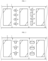
- step B) is a step of forming the cutting guide line in a region on the separator sheet corresponding to the region between the adjacent electrodes adjacent to each other among the electrodes disposed while being spaced apart from one another.
- step B) is a step of forming a plurality of through-holes along the width direction of the pre-cell.
- step B) is a step of forming the through-holes in such a manner that the through-holes may be formed with a relatively higher density at the central region of the pre-cell in the width direction, as compared to the other regions.
- step B) is a step of forming the through-holes in such a manner that the through-holes may be formed with a relatively higher density at the central region of the pre-cell and at both end regions of the pre-cell in the width direction, as compared to the other regions.
- step B) is a step of forming the through-holes in such a manner that the sum of the lengths of the through-holes extended along the width direction of the pre-cell may be 0.01-30% based on the total length of the pre-cell in the width direction.
- step B) is a step of forming the through-holes in such a manner that the length of the through-hole extended along the direction perpendicular to the width direction of the pre-cell may be 1-5% based on the interval of the adjacent electrodes.
- an apparatus for manufacturing unit cells including:
- the apparatus for manufacturing unit cells as defined in the ninth embodiment wherein the hole-forming unit includes a laser irradiation section.
- the apparatus for manufacturing unit cells as defined in the ninth or the tenth embodiment wherein the hole-forming unit is configured to form the through-holes in such a manner that the through-holes may be formed with a relatively higher density at the central region of the pre-cell in the width direction, as compared to the other regions.
- the apparatus for manufacturing unit cells as defined in any one of the ninth to the eleventh embodiments wherein the hole-forming unit is configured to form the through-holes in such a manner that the through-holes may be formed with a relatively higher density at the central region of the pre-cell and at both end regions of the pre-cell in the width direction, as compared to the other regions.
- the apparatus for manufacturing unit cells as defined in any one of the ninth to the twelfth embodiments wherein the hole-forming unit is configured to form the through-holes in such a manner that the sum of the lengths of the through-holes extended along the width direction of the pre-cell may be 0.01-30% based on the total length of the pre-cell in the width direction.
- the apparatus for manufacturing unit cells as defined in any one of the ninth to the thirteenth embodiments wherein the hole-forming unit is configured to form the through-holes in such a manner that the length of the through-hole extended along the direction perpendicular to the width direction of the pre-cell may be 1-5% based on the interval of the adjacent electrodes.
- the method and apparatus for manufacturing unit cells according to the present disclosure can increase cutting accuracy during the manufacture of unit cells by forming a cutting guide line, before carrying out cutting, and thus can reduce cutting defects and can improve the production yield of unit cells.
- ⁇ a part includes an element' does not preclude the presence of any additional elements but means that the part may further include the other elements.
- ⁇ A and/or B' means ⁇ A, B or both of them'.
- a method for manufacturing unit cells including the steps of:
- A) prepared is a pre-cell including a first separator sheet and a plurality of first electrodes disposed on the first separator sheet while being spaced apart from one another.
- the first separator sheet is an element which is disposed between a positive electrode and a negative electrode to prevent a short and to allow migration of ions, and includes a porous polymer substrate, and a porous coating layer disposed on at least one surface of the porous polymer substrate and formed of a mixture of inorganic particles with a binder polymer.
- the porous polymer substrate, the inorganic particles and the binder polymer are not particularly limited, as long as they meet the objects of the present disclosure.
- the porous polymer substrate may include a polyolefin resin, such as polyethylene, polypropylene, polybutylene or polypentene, having a melting point of less than 200°C.
- the inorganic particles may include ZrO 2 , BaTiO 3 , hafnia (HfO 2 ), SrTiO 3 , SnO 2 , CeO 2 , MgO, NiO, CaO, ZnO, ZrO 2 , Y 2 O 3 , Al 2 O 3 , TiO 2 , AlOOH, Al(OH) 3 , SiC, a mixture thereof, or the like.
- the binder polymer may include any one selected from the group consisting of poly(vinylidene fluoride-co-hexafluoropropylene) (PVDF-HFP), poly(vinylidene fluoride-co-chlorotrifluoroethylene), poly(vinylidene fluoride-co-tetrafluoroethylene), poly(vinylidene fluoride-co-trichloroethylene), poly(methyl methacrylate), poly(vinyl pyrrolidone), poly(vinyl alcohol), poly(ethylene-co-vinyl acetate), cellulose acetate, cellulose acetate butyrate, cellulose acetate propionate, pullulan, carboxymethyl cellulose and styrene-butadiene rubber, or two or more of them.
- PVDF-HFP poly(vinylidene fluoride-co-hexafluoropropylene)
- PVDF-HFP poly(vinylidene fluoride-co-ch
- the inorganic particles are attached to one another by the binder polymer so that they may retain their binding states (i.e. the binder polymer interconnects and fixes the inorganic filler particles), and the porous coating layer is bound to the porous polymer substrate by the binder polymer.
- the inorganic filler particles in the porous coating layer are present substantially in contact with one another, and the interstitial volumes formed among the inorganic particles while they are in contact with one another may form pores of the porous coating layer.
- the first electrode may be any one of the positive electrode and the negative electrode, and particularly, may be an electrode obtained by applying a slurry containing an electrode active material onto an electrode current collector, carrying out drying and pressing, and cutting the resultant product into a predetermined size.
- the first electrode is disposed on the first separator sheet, and particularly, a plurality of the first electrodes cut into a predetermined size are disposed on the first separator sheet in such a manner that the electrode may be spaced apart from one another by a predetermined interval. In this manner, a pre-cell may be obtained.
- 'pre-cell' means a laminate including at least one type of electrodes stacked on at least one separator sheet.
- the pre-cell may be subjected to lamination, after at least one type of electrodes are stacked on at least one separator sheet.
- the pre-cell including the first electrodes stacked on the first separator sheet may further include a second separator sheet and/or a second electrode.
- the pre-cell may be a laminate having a layered structure, such as [first separator sheet/first electrode], [first separator sheet/first electrode/second separator sheet], or [first separator sheet/first electrode/second separator sheet/second electrode].
- the first electrodes may be disposed on the first separator sheet, while being spaced apart from one another with a predetermined interval
- the second electrodes are those having the opposite polarity to the first electrodes and may be disposed on the second separator sheet with a predetermined interval.
- the separator sheet when lamination is carried out after at least one type of electrodes are stacked on at least one separator sheet, the separator sheet may be bound to the electrodes.
- heat and/or pressure may be applied to the laminate in which at least one separator and at least one type of electrodes are stacked, by using a pair of pressurization rollers having a structure capable of self-heating or heated by a separate heating device so that the separator sheet may be bound to the electrodes.
- the pre-cell may be a laminate including at least one separator sheet and at least one type of electrodes bound to each other.
- a cutting guide line including a plurality of though-holes spaced apart from one another is formed on the pre-cell.
- Step B) is configured to increase the cutting accuracy in step C) by forming a cutting guide line on the pre-cell, before the following step C) of cutting the pre-cell.
- the cutting guide line means an imaginary linear line by which a plurality of through-holes are connected.
- the through-holes may be formed in a region on the separator sheet corresponding to the region between the adjacent electrodes adjacent to each other among the electrodes disposed while being spaced apart from one another.
- the through-holes may be formed along the width direction of the pre-cell.
- the through-holes are those formed to penetrate through at least one separator sheet provided in the pre-cell.
- the through-holes may be substantially circular through-holes having a substantially regular diameter, or substantially oval through-holes with a longer axis and a shorter axis having a different length.
- cutting defects may be generated, and for example, a partial region of the pre-cell may not be cut or may show an irregular cutting section, in the case of a separator having an increased width depending on cell design or a separator having high strength, or due to the characteristics, such as a cutter shape, of the apparatus for manufacturing the separator.
- the position and density of the through-holes are controlled in forming the through-holes on the pre-cell, thereby facilitating cutting in the whole regions on the pre-cell and increasing the cutting accuracy.
- the density of the through-holes formed on the pre-cell may be controlled in such a manner that a region with frequent cutting defects may have a relatively higher density as compared to the other regions.
- the through-holes may be formed in such a manner that the density of the through-holes may be relatively higher at the central region of the pre-cell in the width direction, as compared to the other regions, or the density of the through-holes may be relatively higher at the central region of the pre-cell and at both end regions of the pre-cell in the width direction, as compared to the other regions.
- the through-holes may be formed in such a manner that the sum of the lengths of the through-holes extended along the width direction of the pre-cell may be 0.01-30% based on the total length of the pre-cell in the width direction.
- ⁇ sum of the lengths of the through-holes extended along the width direction of the pre-cell' means the sum of the lengths of the through-holes in the width direction of the pre-cell.
- ⁇ sum of the lengths of the through-holes extended along the width direction of the pre-cell' means [d1 + d2 + d3 + d4], or [d1' + d2' + d3' + d4'].
- the through-holes are formed within the above-defined range, it is possible to assist improving the cutting accuracy in the following step C), and to prevent generation of deformation, such as wrinkles or fine orientation, caused by concentration of the tension applied by a roll-to-roll system in the manufacturing process at the region having no through-holes on the separator sheet.
- the through-holes may be formed in such a manner that the length of the through-hole extended along the direction perpendicular to the width direction of the pre-cell may be 1-5% based on the interval of the adjacent electrodes.
- ⁇ length of the through-hole extended along the direction perpendicular to the width direction of the pre-cell' means the length of the through-hole extended in the direction from one electrode to the electrode adjacent thereto.
- ⁇ length of the through-hole extended along the direction perpendicular to the width direction of the pre-cell' means r1, r2, r3, r1', r2', or r3'.
- the through-holes are formed within the above-defined range, it is possible to provide uniform appearance to the section after cutting, while not affecting the electrode thermally during the formation of the through-holes.
- C) the pre-cell is cut along the cutting guide line to form a plurality of unit cells.
- the through-holes formed on the separator sheet while being spaced apart from one another determine the cutting guide line. Therefore, it is possible to obtain unit cells in which at least one separator sheet and at least one type of electrodes are stacked, such as unit cells having a layered structure of [first separator sheet/first electrode], [first separator sheet/first electrode/second separator sheet], or [first separator sheet/first electrode/second separator sheet/second electrode].
- an apparatus for manufacturing unit cells including:
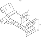
- FIG. 3 is a schematic view illustrating the apparatus for manufacturing unit cells according to the present disclosure.
- the apparatus for manufacturing unit cells includes a hole-forming unit 10 and a cutting unit 20.
- the apparatus for manufacturing unit cells may further include a lamination unit (not shown) and/or a conveying unit (not shown) and/or a controlling unit (not shown), or the like, besides the above-mentioned constitutional elements.
- the hole-forming unit 10 is configured to form a cutting guide line including a plurality of though-holes 11 spaced apart from one another, on a pre-cell including a separator sheet and electrodes 2 disposed on the separator sheet.
- the hole-forming unit 10 may include at least one laser irradiation section 12.
- the laser irradiation section 12 irradiates laser beams in the direction substantially perpendicular to the pre-cell to form through-holes 11.
- the hole-forming unit 10 forms a plurality of through-holes 11 in a region on the separator sheet corresponding to the region between the adjacent electrodes adjacent to each other among the electrodes disposed while being spaced apart from one another.
- the cutting guide line means an imaginary linear line by which a plurality of through-holes are connected.
- the hole-forming unit 10 may be provided with a plurality of laser irradiation sections 12 disposed in predetermined positions in such a manner that a plurality of through-holes 11 contained in one cutting line may be formed at the same time.
- the hole-forming unit 10 may be provided with at least one actuator (not shown), the motion of which is controlled by the user or by a controlling unit 50 to displace the position of at least one laser irradiation section 12.
- one cutting line may be formed by irradiating laser beams many times.
- the hole-forming unit 10 may control the position and density of the through-holes 11 formed on the pre-cell by using a plurality of laser irradiation sections 12 disposed in pre-determined positions, or by using at least one laser irradiation section 12, the motion of which is controlled by the controlling unit 50 as described hereinafter. In this manner, it is possible to prevent generation of cutting defects, such as a failure in cutting in a partial region of the pre-cell or a non-uniform cutting section, thereby facilitating cutting in the whole regions on the pre-cell and increasing the cutting accuracy.
- the density of the through-holes 11 formed on the pre-cell may be controlled in such a manner that a region with frequent cutting defects may have a relatively higher density as compared to the other regions.
- the through-holes 11 may be formed in such a manner that the density of the through-holes 11 may be relatively higher at the central region of the pre-cell in the width direction, as compared to the other regions, or the density of the through-holes 11 may be relatively higher at the central region of the pre-cell and at both end regions of the pre-cell in the width direction, as compared to the other regions.
- the through-holes 11 may be formed in such a manner that the sum of the lengths of the through-holes 11 extended along the width direction of the pre-cell may be 0.01-30% based on the total length of the pre-cell in the width direction.
- the through-holes 11 are formed within the above-defined range, it is possible to assist improving the cutting accuracy in step C), and to prevent generation of deformation, such as wrinkles or fine orientation, caused by concentration of the tension applied by a roll-to-roll system in the manufacturing process at the region having no through-holes 11 on the separator sheet.
- the through-holes 11 may be formed in such a manner that the length of the through-hole 11 extended along the direction perpendicular to the width direction of the pre-cell may be 1-5% based on the interval of the adjacent electrodes.
- the through-holes 11 are formed within the above-defined range, it is possible to accomplish sharp cutting by providing uniform appearance to the section after cutting, while not affecting the electrode thermally during the formation of the through-holes 11.
- the cutting unit 20 is configured to cut the pre-cell along the cutting guide line including a plurality of through-holes 11.
- the cutting unit 20 may include a blade cutter.
- the blade cutter means a type of cutter including a top blade 21 and/or a bottom blade 22, wherein at least one of the top blade and the bottom blade cuts the substrate sheet, while moving vertically to the direction of conveying the substrate sheet.
- the terms 'top blade' and 'bottom blade' are not limited to those disposed at the top and bottom in the direction of gravity, but may cover cutters each of which is present in one direction and the opposite direction.
- a top blade having a substantially reverse-V ( ⁇ ) shape may be used when cutting the pre-cell.
- the blade insertion length is short to minimize the motion and to reduce the cutting time.
- the central region in the width direction of the pre-cell may cause cutting defects more easily as compared to the other regions due to the shape of the blade cutter. Therefore, according to an embodiment of the present disclosure, a plurality of through-holes 11 is formed in a region with frequent cutting defects, and the density of the through-holes 11 is controlled to facilitate cutting in the whole regions on the pre-cell and to increase the cutting accuracy.
- the lamination unit may include a pair of pressurization rollers.
- the lamination unit may pressurize a laminate in which at least one separator sheet 1 and at least one type of electrodes 2 are stacked so that they may be bound to each other.
- the pressurization rollers may further apply heat in addition to pressure.
- the pressurization rollers may have a structure capable of self-heating or may be heated by a separate heating device.
- the pre-cell before forming the cutting guide line including a plurality of through-holes 11 disposed on the pre-cell while being spaced apart from one another, the pre-cell may be passed through a lamination unit 30 so that the separator sheet 1 and the electrode 2 disposed on the separator sheet 1 may be bound to each other.
- the conveying unit may be provided to convey the pre-cell including the separator sheet 1 and the electrodes 2 disposed on the separator sheet 1 in one direction in the apparatus for manufacturing unit cells.
- the conveying unit may include a conveyer.
- the conveying unit may include a belt conveyor.
- the controlling unit may be positioned inside and/or outside of the apparatus for manufacturing unit cells according to the present disclosure, and linked to each of the units described hereinabove to control the operation of each unit and the operational interrelation of the units.
- the controlling unit may control the operation of an electrode-arranging unit (not shown) through control signals to dispose the electrodes 2 at a regular interval on the separator sheet.
- the controlling unit may control the operation of the hole-forming unit 10 through control signals to form a plurality of through-holes 11 in each region between the electrodes spaced apart from each other, and may control the position and density of the through-holes 11 formed on the pre-cell.
- Example 1 and Comparative Example 1 were prepared according to the following methods.
- a pre-cell was prepared by disposing negative electrodes cut into a size of 94 mm ⁇ 510 mm on each separator sheet so that the separator sheet, the negative electrode and the separator sheet might be stacked in the listed order with the two separator sheets as substrates.
- the negative electrode cut into such a size was disposed between the separator sheets.
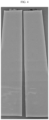
- the apparatus for manufacturing unit cells according to the present disclosure was used to form a cutting guide line including through-holes on the pre-cell prepared as described above.
- the through-holes were formed in a straight line along the width direction of the pre-cell in a circular shape having a diameter of 50 ⁇ m.
- the sum of the lengths of the through-holes extended along the width direction of the pre-cell was 0.48% based on the total length in the width direction of the pre-cell.
- the pre-cell was cut by using a blade having a reverse-V shape along the cutting guide line to obtain a plurality of unit cells.
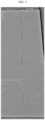
- Unit cells were obtained in the same manner as Example 1, except that no cutting guide line was formed.
- Example 1 shows a more uniform cutting section of each unit cell and accomplishes sharper cutting, as compared to Comparative Example 1.
Landscapes
- Engineering & Computer Science (AREA)
- Chemical Kinetics & Catalysis (AREA)
- General Chemical & Material Sciences (AREA)
- Electrochemistry (AREA)
- Manufacturing & Machinery (AREA)
- Chemical & Material Sciences (AREA)
- Mechanical Engineering (AREA)
- Life Sciences & Earth Sciences (AREA)
- Forests & Forestry (AREA)
- Physics & Mathematics (AREA)
- Optics & Photonics (AREA)
- Plasma & Fusion (AREA)
- Battery Electrode And Active Subsutance (AREA)
- Cell Separators (AREA)
- Secondary Cells (AREA)
Applications Claiming Priority (2)
| Application Number | Priority Date | Filing Date | Title |
|---|---|---|---|
| KR1020210111257A KR102863478B1 (ko) | 2021-08-23 | 2021-08-23 | 단위셀의 제조 방법 및 제조 장치 |
| PCT/KR2022/012528 WO2023027456A1 (ko) | 2021-08-23 | 2022-08-22 | 단위셀의 제조 방법 및 제조 장치 |
Publications (2)
| Publication Number | Publication Date |
|---|---|
| EP4243136A1 true EP4243136A1 (de) | 2023-09-13 |
| EP4243136A4 EP4243136A4 (de) | 2024-07-17 |
Family
ID=85323320
Family Applications (1)
| Application Number | Title | Priority Date | Filing Date |
|---|---|---|---|
| EP22861666.0A Pending EP4243136A4 (de) | 2021-08-23 | 2022-08-22 | Verfahren und vorrichtung zur herstellung einer einheitszelle |
Country Status (6)
| Country | Link |
|---|---|
| US (1) | US12337494B2 (de) |
| EP (1) | EP4243136A4 (de) |
| JP (1) | JP7592162B2 (de) |
| KR (1) | KR102863478B1 (de) |
| CN (1) | CN116783029A (de) |
| WO (1) | WO2023027456A1 (de) |
Families Citing this family (3)
| Publication number | Priority date | Publication date | Assignee | Title |
|---|---|---|---|---|
| KR102863478B1 (ko) * | 2021-08-23 | 2025-09-22 | 주식회사 엘지에너지솔루션 | 단위셀의 제조 방법 및 제조 장치 |
| DE102023115225A1 (de) * | 2023-06-12 | 2024-12-12 | Körber Technologies Gmbh | Vorrichtung, Verfahren und Separatorbahn für die Energiezellen, insbesondere Batteriezellen, produzierende Industrie |
| EP4723266A1 (de) * | 2023-08-03 | 2026-04-08 | LG Energy Solution, Ltd. | Verfahren zur herstellung einer elektrodenanordnung |
Family Cites Families (35)
| Publication number | Priority date | Publication date | Assignee | Title |
|---|---|---|---|---|
| US4756717A (en) * | 1981-08-24 | 1988-07-12 | Polaroid Corporation | Laminar batteries and methods of making the same |
| US4664993A (en) * | 1981-08-24 | 1987-05-12 | Polaroid Corporation | Laminar batteries and methods of making the same |
| JP2529176B2 (ja) * | 1982-12-15 | 1996-08-28 | 松下電器産業株式会社 | 電池の渦巻状極板群構成装置 |
| CA2259785C (en) * | 1999-01-19 | 2008-07-29 | Peter E. Sandford | Jogger member, system and method for mounting jogger members and female and male blanking dies provided therewith |
| US6508901B2 (en) | 2001-03-16 | 2003-01-21 | Wilson Greatbatch Ltd. | Thermo-encapsulating system and method |
| US6833593B2 (en) * | 2001-11-09 | 2004-12-21 | Thin Film Electronics Asa | Electrode means, a method for its manufacture, an apparatus comprising the electrode means as well as use of the latter |
| JP2005190709A (ja) * | 2003-12-24 | 2005-07-14 | Sanyo Electric Co Ltd | アルカリ蓄電池用極板及びアルカリ蓄電池 |
| US20090047350A1 (en) * | 2007-08-17 | 2009-02-19 | Ramesh Bangalore | Perforated water soluble polymer based edible films |
| JP5426989B2 (ja) | 2009-10-15 | 2014-02-26 | コマツNtc株式会社 | 積層型電池製造装置 |
| JP2011204612A (ja) * | 2010-03-26 | 2011-10-13 | Mitsubishi Heavy Ind Ltd | 電極板製造装置 |
| KR101264742B1 (ko) * | 2011-08-03 | 2013-05-14 | 삼성에스디아이 주식회사 | 전극판 형성 장치 |
| DE102011081263A1 (de) * | 2011-08-12 | 2013-02-14 | Sgl Carbon Se | Verfestigte Faserbündel |
| EP3007871B1 (de) * | 2013-06-12 | 2017-07-26 | The Procter and Gamble Company | Perforator zur herstellung einer nichtlinearen bruchlinie |
| TWI521775B (zh) * | 2013-06-28 | 2016-02-11 | Lg化學股份有限公司 | 包括切割隔板程序之製造電極組合體的方法 |
| KR101521543B1 (ko) * | 2013-09-06 | 2015-05-20 | 주식회사 제우스 | 강화유리 절단방법 |
| JP2015130297A (ja) * | 2014-01-08 | 2015-07-16 | 日産自動車株式会社 | 電極の製造方法、電極板、及び2次電池 |
| JP2015170568A (ja) | 2014-03-10 | 2015-09-28 | 株式会社豊田自動織機 | 電極の製造方法および電極の製造装置 |
| KR101726785B1 (ko) | 2014-11-03 | 2017-04-13 | 주식회사 엘지화학 | 스티치 커팅부를 포함하는 전극조립체 제조장치 및 이를 사용하여 제조된 전극조립체 |
| JP6488764B2 (ja) | 2015-02-27 | 2019-03-27 | 株式会社豊田自動織機 | セパレータ付き電極の製造装置及びセパレータ付き電極の製造方法 |
| JP2016216186A (ja) | 2015-05-20 | 2016-12-22 | 株式会社豊田自動織機 | 加工装置 |
| WO2018139349A1 (ja) | 2017-01-24 | 2018-08-02 | 三洋電機株式会社 | 電池用極板の製造方法、電池の製造方法、及び電池 |
| JP6760193B2 (ja) | 2017-04-20 | 2020-09-23 | トヨタ自動車株式会社 | 電極積層体の製造装置 |
| DE102017216193A1 (de) | 2017-09-13 | 2019-03-14 | Robert Bosch Gmbh | Verfahren zur Herstellung von Elektroden |
| JP6962163B2 (ja) * | 2017-12-08 | 2021-11-05 | 株式会社村田製作所 | 積層電極体の製造装置 |
| GB2575686B (en) * | 2018-07-20 | 2021-11-17 | Dyson Technology Ltd | Energy storage device |
| CN113272051B (zh) | 2019-01-09 | 2024-11-15 | 三菱制纸株式会社 | 半透膜支撑体及半透膜支撑体的制造方法 |
| KR102794373B1 (ko) | 2019-01-25 | 2025-04-11 | 주식회사 엘지에너지솔루션 | 전극 조립체 제조방법과, 이를 통해 제조된 전극 조립체 및 이차전지 |
| KR102817871B1 (ko) | 2019-06-13 | 2025-06-09 | 삼성전자 주식회사 | 배터리 스택 및 그 제조방법 |
| KR102679276B1 (ko) | 2019-07-11 | 2024-06-28 | 현대모비스 주식회사 | 라이다 센서 장치 및 그 제어 방법 |
| US20220200038A1 (en) * | 2019-12-10 | 2022-06-23 | Lg Energy Solution, Ltd. | Unit cell, and method and apparatus for manufacturing same |
| KR102785345B1 (ko) * | 2020-06-15 | 2025-03-25 | 주식회사 엘지에너지솔루션 | 이차전지 제조설비 및 그의 제조방법 |
| KR102863478B1 (ko) * | 2021-08-23 | 2025-09-22 | 주식회사 엘지에너지솔루션 | 단위셀의 제조 방법 및 제조 장치 |
| US12371325B2 (en) * | 2021-12-23 | 2025-07-29 | Integrated Graphene Holding limited | Laser-induced carbon nanostructures |
| CN116690657B (zh) * | 2022-02-25 | 2025-11-18 | 宁德时代新能源科技股份有限公司 | 裁切装置、裁切方法以及电池制造设备 |
| CN121941571A (zh) * | 2023-09-28 | 2026-04-28 | 艾诺维克斯公司 | 用于加工电极材料的移动带材的装置 |
-
2021
- 2021-08-23 KR KR1020210111257A patent/KR102863478B1/ko active Active
-
2022
- 2022-08-22 US US18/036,774 patent/US12337494B2/en active Active
- 2022-08-22 EP EP22861666.0A patent/EP4243136A4/de active Pending
- 2022-08-22 CN CN202280008720.5A patent/CN116783029A/zh active Pending
- 2022-08-22 WO PCT/KR2022/012528 patent/WO2023027456A1/ko not_active Ceased
- 2022-08-22 JP JP2023526643A patent/JP7592162B2/ja active Active
Also Published As
| Publication number | Publication date |
|---|---|
| CN116783029A (zh) | 2023-09-19 |
| WO2023027456A1 (ko) | 2023-03-02 |
| US12337494B2 (en) | 2025-06-24 |
| JP7592162B2 (ja) | 2024-11-29 |
| EP4243136A4 (de) | 2024-07-17 |
| KR102863478B1 (ko) | 2025-09-22 |
| US20230405858A1 (en) | 2023-12-21 |
| JP2023548502A (ja) | 2023-11-17 |
| KR20230029136A (ko) | 2023-03-03 |
Similar Documents
| Publication | Publication Date | Title |
|---|---|---|
| EP4243136A1 (de) | Verfahren und vorrichtung zur herstellung einer einheitszelle | |
| US12134259B2 (en) | Laminated multilayer membranes, separators, batteries, and methods | |
| KR102112194B1 (ko) | 이차전지 셀 파우치용 시트 제조장치 | |
| EP2899776B1 (de) | Verfahren zur herstellung eines separators für eine lithium-sekundärbatterie | |
| CN108604702B (zh) | 具有改善的润湿性的二次电池用单元电池及其制造方法 | |
| US10374203B2 (en) | Heat-diffusible separation film and secondary cell comprising the same | |
| KR20240017892A (ko) | 전극 조립체 | |
| EP4248513B1 (de) | Elektrodenanordnung | |
| CN115244746B (zh) | 单元电芯制造设备和方法 | |
| JP7442655B2 (ja) | 電極の圧延装置及び電極の圧延方法 | |
| JP7835366B2 (ja) | 電極供給装置、これを利用する電極組立体製造装置、電極供給方法、およびこれを利用する電極組立体製造方法 | |
| ES2928898T3 (es) | Celda unitaria para batería secundaria con humectabilidad mejorada y procedimiento para fabricar la misma | |
| CN107627335B (zh) | 分离器制造方法 | |
| KR20170029955A (ko) | 분리막 제조방법 및 이에 의해 제조된 분리막 | |
| CN120345098A (zh) | 电极组件及电极组件的制造方法 | |
| CN121511201A (zh) | 隔膜卷绕卷、隔膜卷绕卷制造方法、电极组件制造装置和电极组件制造方法 | |
| KR20240076560A (ko) | 전극 조립체 제조 장치 및 전극 조립체 제조 방법 | |
| CN120604346A (zh) | 电极片制造装置及使用电极片制造装置的电极片制造方法 | |
| KR20230050178A (ko) | 코팅바 및 이를 이용한 분리막 제조방법 |
Legal Events
| Date | Code | Title | Description |
|---|---|---|---|
| STAA | Information on the status of an ep patent application or granted ep patent |
Free format text: STATUS: THE INTERNATIONAL PUBLICATION HAS BEEN MADE |
|
| PUAI | Public reference made under article 153(3) epc to a published international application that has entered the european phase |
Free format text: ORIGINAL CODE: 0009012 |
|
| STAA | Information on the status of an ep patent application or granted ep patent |
Free format text: STATUS: REQUEST FOR EXAMINATION WAS MADE |
|
| 17P | Request for examination filed |
Effective date: 20230606 |
|
| AK | Designated contracting states |
Kind code of ref document: A1 Designated state(s): AL AT BE BG CH CY CZ DE DK EE ES FI FR GB GR HR HU IE IS IT LI LT LU LV MC MK MT NL NO PL PT RO RS SE SI SK SM TR |
|
| A4 | Supplementary search report drawn up and despatched |
Effective date: 20240619 |
|
| RIC1 | Information provided on ipc code assigned before grant |
Ipc: B26D 1/04 20060101ALI20240613BHEP Ipc: B26F 1/14 20060101ALI20240613BHEP Ipc: B26D 7/08 20060101ALI20240613BHEP Ipc: B23K 26/382 20140101ALI20240613BHEP Ipc: H01M 10/04 20060101AFI20240613BHEP |
|
| DAV | Request for validation of the european patent (deleted) | ||
| DAX | Request for extension of the european patent (deleted) |