EP4243103A1 - Perowskitsolarzelle und herstellungsverfahren dafür sowie elektrische vorrichtung - Google Patents
Perowskitsolarzelle und herstellungsverfahren dafür sowie elektrische vorrichtung Download PDFInfo
- Publication number
- EP4243103A1 EP4243103A1 EP22787318.9A EP22787318A EP4243103A1 EP 4243103 A1 EP4243103 A1 EP 4243103A1 EP 22787318 A EP22787318 A EP 22787318A EP 4243103 A1 EP4243103 A1 EP 4243103A1
- Authority
- EP
- European Patent Office
- Prior art keywords
- solar cell
- perovskite solar
- cell device
- sealant
- back plate
- Prior art date
- Legal status (The legal status is an assumption and is not a legal conclusion. Google has not performed a legal analysis and makes no representation as to the accuracy of the status listed.)
- Granted
Links
Images

Classifications
-
- H—ELECTRICITY
- H10—SEMICONDUCTOR DEVICES; ELECTRIC SOLID-STATE DEVICES NOT OTHERWISE PROVIDED FOR
- H10K—ORGANIC ELECTRIC SOLID-STATE DEVICES
- H10K30/00—Organic devices sensitive to infrared radiation, light, electromagnetic radiation of shorter wavelength or corpuscular radiation
- H10K30/40—Organic devices sensitive to infrared radiation, light, electromagnetic radiation of shorter wavelength or corpuscular radiation comprising a p-i-n structure, e.g. having a perovskite absorber between p-type and n-type charge transport layers
-
- H—ELECTRICITY
- H01—ELECTRIC ELEMENTS
- H01G—CAPACITORS; CAPACITORS, RECTIFIERS, DETECTORS, SWITCHING DEVICES, LIGHT-SENSITIVE OR TEMPERATURE-SENSITIVE DEVICES OF THE ELECTROLYTIC TYPE
- H01G9/00—Electrolytic capacitors, rectifiers, detectors, switching devices, light-sensitive or temperature-sensitive devices; Processes of their manufacture
- H01G9/0029—Processes of manufacture
-
- H—ELECTRICITY
- H01—ELECTRIC ELEMENTS
- H01G—CAPACITORS; CAPACITORS, RECTIFIERS, DETECTORS, SWITCHING DEVICES, LIGHT-SENSITIVE OR TEMPERATURE-SENSITIVE DEVICES OF THE ELECTROLYTIC TYPE
- H01G9/00—Electrolytic capacitors, rectifiers, detectors, switching devices, light-sensitive or temperature-sensitive devices; Processes of their manufacture
- H01G9/20—Light-sensitive devices
-
- H—ELECTRICITY
- H10—SEMICONDUCTOR DEVICES; ELECTRIC SOLID-STATE DEVICES NOT OTHERWISE PROVIDED FOR
- H10K—ORGANIC ELECTRIC SOLID-STATE DEVICES
- H10K30/00—Organic devices sensitive to infrared radiation, light, electromagnetic radiation of shorter wavelength or corpuscular radiation
- H10K30/50—Photovoltaic [PV] devices
-
- H—ELECTRICITY
- H10—SEMICONDUCTOR DEVICES; ELECTRIC SOLID-STATE DEVICES NOT OTHERWISE PROVIDED FOR
- H10K—ORGANIC ELECTRIC SOLID-STATE DEVICES
- H10K30/00—Organic devices sensitive to infrared radiation, light, electromagnetic radiation of shorter wavelength or corpuscular radiation
- H10K30/80—Constructional details
- H10K30/88—Passivation; Containers; Encapsulations
-
- H—ELECTRICITY
- H10—SEMICONDUCTOR DEVICES; ELECTRIC SOLID-STATE DEVICES NOT OTHERWISE PROVIDED FOR
- H10K—ORGANIC ELECTRIC SOLID-STATE DEVICES
- H10K71/00—Manufacture or treatment specially adapted for the organic devices covered by this subclass
- H10K71/10—Deposition of organic active material
- H10K71/12—Deposition of organic active material using liquid deposition, e.g. spin coating
-
- H—ELECTRICITY
- H10—SEMICONDUCTOR DEVICES; ELECTRIC SOLID-STATE DEVICES NOT OTHERWISE PROVIDED FOR
- H10K—ORGANIC ELECTRIC SOLID-STATE DEVICES
- H10K71/00—Manufacture or treatment specially adapted for the organic devices covered by this subclass
- H10K71/40—Thermal treatment, e.g. annealing in the presence of a solvent vapour
-
- H—ELECTRICITY
- H10—SEMICONDUCTOR DEVICES; ELECTRIC SOLID-STATE DEVICES NOT OTHERWISE PROVIDED FOR
- H10K—ORGANIC ELECTRIC SOLID-STATE DEVICES
- H10K71/00—Manufacture or treatment specially adapted for the organic devices covered by this subclass
- H10K71/811—Controlling the atmosphere during processing
-
- H—ELECTRICITY
- H10—SEMICONDUCTOR DEVICES; ELECTRIC SOLID-STATE DEVICES NOT OTHERWISE PROVIDED FOR
- H10K—ORGANIC ELECTRIC SOLID-STATE DEVICES
- H10K85/00—Organic materials used in the body or electrodes of devices covered by this subclass
- H10K85/50—Organic perovskites; Hybrid organic-inorganic perovskites [HOIP], e.g. CH3NH3PbI3
-
- Y—GENERAL TAGGING OF NEW TECHNOLOGICAL DEVELOPMENTS; GENERAL TAGGING OF CROSS-SECTIONAL TECHNOLOGIES SPANNING OVER SEVERAL SECTIONS OF THE IPC; TECHNICAL SUBJECTS COVERED BY FORMER USPC CROSS-REFERENCE ART COLLECTIONS [XRACs] AND DIGESTS
- Y02—TECHNOLOGIES OR APPLICATIONS FOR MITIGATION OR ADAPTATION AGAINST CLIMATE CHANGE
- Y02E—REDUCTION OF GREENHOUSE GAS [GHG] EMISSIONS, RELATED TO ENERGY GENERATION, TRANSMISSION OR DISTRIBUTION
- Y02E10/00—Energy generation through renewable energy sources
- Y02E10/50—Photovoltaic [PV] energy
- Y02E10/549—Organic PV cells
Definitions
- This application relates to the field of battery technologies, and in particular, to a perovskite solar cell, a preparation method therefor, and an electrical device.
- perovskite materials are easy to decompose under actions of light, heat, water, and oxygen, reducing photoelectric conversion efficiency of perovskite solar cells. Therefore, it is necessary to ensure that a perovskite solar cell device is prepared with good sealing performance.
- the perovskite battery device with only good sealing performance ensured during packaging has a limited effect on prolonging service life of a perovskite solar cell.
- Embodiments of this application are intended to provide a perovskite solar cell, a preparation method thereof, and an electric device, so as to prolong service life of the perovskite solar cell.
- a first aspect of this application provides a perovskite solar cell, including:
- the 10%-100% ammonia gas and the residual inert gas are contained in a structure of the perovskite solar cell containing the organic amine cation, which can effectively inhibit migration and decomposition of organic amine cations in the perovskite material and improves thermal stability of the perovskite solar cell device, thereby improving light conversion efficiency and service life of the perovskite solar cell.
- A includes at least one of CH 3 NH 3 + and HC(NH 2 ) 2 + .
- B is at least one of Pb 2+ , Sn 2+ , and Ge 2+ .
- A further includes at least one of Cs + , Rb + , and K + .
- the inert gas includes at least one of nitrogen, argon, helium, and neon.
- the volume fraction of the ammonia gas in the sealed cavity is 30%-90%.
- the volume fraction of the ammonia gas in the sealed cavity is 50%-70%.
- the volume fraction of the ammonia gas being controlled within the above ranges in the sealed cavity can ensure various advantages such as low production costs, high light conversion efficiency of the solar cell, and operation safety.
- the perovskite solar cell further includes a sealing element, where the sealing element connects the transparent substrate and the back plate to form the sealed cavity.
- the sealing element is a sealant.
- the sealant is around a periphery of the perovskite solar cell device, and the back plate is fastened to the perovskite solar cell device using the sealant.
- the sealant is further located on at least part of a surface or the entire surface on a side of the back plate facing toward the perovskite solar cell device.
- a material of the transparent substrate is glass or polyethylene terephthalate.
- a material of the back plate is glass or polyethylene terephthalate.
- a second aspect of this application provides a preparation method of perovskite solar cell, including:
- the perovskite solar cell device is packaged in the preset atmosphere containing the ammonia gas having the volume fraction of 10%-100% and the residual inert gas, so that the perovskite solar cell device is located in the above preset atmosphere; and the present atmosphere can inhibit migration and decomposition of organic amine cations in the perovskite material containing the organic amine cation.
- A in ABX 3 , includes at least one of CH 3 NH 3 + and HC(NH 2 ) 2 + .
- B is at least one of Pb 2+ , Sn 2+ , and Ge 2+ .
- A further includes at least one of Cs + , Rb + , and K + .
- the inert gas includes at least one of nitrogen, argon, helium, and neon.
- the volume fraction of the ammonia gas in the preset atmosphere is 30%-90%.
- the volume fraction of the ammonia gas in the preset atmosphere is 50%-70%.
- Packaging in the above preset atmosphere can allow the preset atmosphere to be packaged inside the perovskite solar cell device, which reduces costs in a manufacturing process when the efficiency and service life of the battery are increased.
- a sealing element is used for packaging.
- the sealing element is a sealant.
- the sealant is applied at a periphery of the perovskite solar cell device, and the back plate is fastened to the perovskite solar cell device using the sealant.
- the sealant is further applied on at least part of a surface or the entire surface on a side of the back plate facing toward the perovskite solar cell device.
- a third aspect of this application provides an electric device, where the electric device includes the perovskite solar cell according to the first aspect, and the perovskite solar cell serves as a power source or an energy storage unit of the electric device.
- Embodiments where specific conditions are not specified, are implemented in accordance with general conditions or those recommended by a manufacturer.
- the reagents or instruments used are all conventional products that can be purchased on the market if no manufacturer is indicated.
- FIG. 1 is a schematic cross-sectional diagram of a perovskite solar cell 100 according to an embodiment of this application.
- this embodiment provides a perovskite solar cell 100, where the perovskite solar cell 100 mainly includes a back plate 110, a transparent substrate 120, and a perovskite solar cell device 130.
- a sealed cavity 101 is formed between the back plate 110 and the transparent substrate 120, and the perovskite solar cell device 130 is located in the sealed cavity 101.
- the perovskite solar cell 100 further includes a sealing element 140, where the sealing element 140 is located between the back plate 110 and the transparent substrate 120, and the back plate 110, the transparent substrate 120, and the sealing element jointly enclose the sealed cavity 101.
- a side of the transparent substrate 120 is provided with a positive electrode leading-out terminal 121 and a negative electrode leading-out terminal 122; a front face of the perovskite solar cell device 130 is connected to the transparent substrate 120; a positive electrode of the perovskite solar cell device 130 is electrically connected to the positive electrode leading-out terminal 121 and a negative electrode of the perovskite solar cell device 130 is connected to the negative electrode leading-out terminal 122; and a back face of the perovskite solar cell device 130 is connected to the back plate 110, the sealing element 140 is located between the back face of the perovskite solar cell device 130 and the back plate 110, and the sealing element 140 seals the perovskite solar cell device 130.
- a material of the transparent substrate 120 is glass.
- a material of the transparent substrate 120 may be another transparent material such as polyethylene terephthalate.
- a material of the back plate 110 is polyethylene terephthalate.
- a material of the back plate 110 may alternatively be glass or another material.
- the sealing element 140 is a sealant; and for example, the sealant may seal the perovskite solar cell device 130 through the following implementations.
- the sealant is applied on an entire surface of the perovskite solar cell device 130 facing away from the transparent substrate 120 and at a periphery of the perovskite solar cell device 130, and the back plate 110 is attached to the sealant to seal the perovskite solar cell device 130; or alternatively, the sealant is applied on a surface of the back plate 110 facing toward the perovskite solar cell device 130, and the back plate 110 is attached to the sealant to seal the perovskite solar cell device 130; and the sealed cavity 101 is present between the sealant and the perovskite solar cell device 130.
- the sealed cavity 101 may be provided in a quantity of one or more, and a plurality of sealed cavities 101 may communicate with each other or not.
- the sealant being applied on the entire surface of the perovskite solar cell device 130 facing away from the transparent substrate 120 helps improve mechanical property of the perovskite solar cell 100, increasing firmness and stability of a packaging structure of the perovskite solar cell 100.
- FIG. 2 is a schematic cross-sectional diagram of a perovskite solar cell 100 according to an embodiment of this application.
- the sealant is around a periphery of the perovskite solar cell device 130 and on a partial surface of the perovskite solar cell device 130 facing away from the transparent substrate 120.
- the sealant may seal the perovskite solar cell device 130 in the following manners.
- the sealant is applied at the periphery of the perovskite solar cell device 130, and the back plate 110 is attached to the sealant to seal the perovskite solar cell device 130.
- the sealant is applied at a periphery of the back plate 110 facing toward the perovskite solar cell device 130, and the back plate 110 is attached to the sealant to seal the perovskite solar cell device 130.
- the sealed cavity 101 is present between the perovskite solar cell device 130 and the back plate 110; or in some embodiments, due to an uneven surface of the perovskite solar cell device 130 or other reasons, there may alternatively be at least one sealed cavity 101 between the perovskite solar cell device 130 and the sealant.
- the above two examples are made with respect to sealing of the perovskite solar cell device 130 using the sealant.
- the sealant may seal the perovskite solar cell device 130 in another manner.
- the sealant is applied at the periphery of the back plate 110 facing toward the perovskite solar cell device 130 and on an entire surface of the back plate 110, and the back plate 110 is attached to the sealant to seal the perovskite solar cell device 130.
- the sealed cavity 101 formed may be located between the sealant and the perovskite solar cell device 130, or may alternatively be located between the perovskite solar cell device 130 and the back plate 110; or the sealed cavity 101 is provided at both the above positions.
- a shape and a quantity of the sealed cavity 101 and whether a plurality of sealed cavities 101 communicate with each other are not limited in this application.
- the sealed cavity 101 accounting for a large volume of the entire perovskite solar cell 100 is merely intended for better identifying the sealed cavity 101 in the figure. This does not mean that the volume accounted by the sealed cavity 101 of the entire perovskite solar cell 100 is as shown in FIG. 1 or FIG. 2 . It should be noted that the volume occupied by the sealed cavity 101 of the entire perovskite solar cell 100 is not limited in the embodiments of this application. During actual production, the sealed cavity 101 may be a cavity deliberately formed during packaging, or may alternatively be a cavity inevitably formed during packaging; or may include both the above cases.
- the sealant is selected from at least one of an epoxy packaging sealant, an organic silicon packaging sealant, a polyurethane packaging sealant, a UV-light curing packaging sealant, ethylene-vinyl acetate copolymer, polyvinyl butyral, ethylene-octene copolymer, polyisobutylene, and a polyolefin packaging sealant.
- the sealant is an epoxy packaging sealant, for example, an epoxy AB sealant including sealant A and sealant B of which a mass ratio is 2:(0.5-1.5), and the mass ratio of sealant A to sealant B may be, for example, 2:0.5, 2:0.8, 2:1, 2:1.2 or 2:1.5.
- the sealing element 140 may not be limited to the sealant.
- another sealing part is used to seal the perovskite solar cell device 130; or no sealing element 140 is used to seal the perovskite solar cell device 130, and the perovskite solar cell device 130 is directly sealed by the transparent substrate 120 and the back plate 110.
- the sealed cavity 101 contains ammonia gas having a volume fraction of 10%-100% and residual inert gas.
- gases in the sealed cavity 101 include the ammonia gas having the volume fraction of 10%-100% and the residual inert gas.
- the volume fraction of the ammonia gas in the sealed cavity 101 may be 50%-90%, 30%-70%, 60%-80%, or the like.
- the volume fraction of the ammonia gas in the sealed cavity 101 may be 10%, 16%, 21%, 30%, 34%, 50%, 60%, 67%, 75%, 80%, 98%, 100%, or the like.
- the inert gas may be at least one of nitrogen, argon, helium, and neon.
- the inert gas is nitrogen.
- the sealed cavity 101 may further include inevitable trace impurity gas during actual production (generally, a volume fraction of the trace impurity gas is less than 1%).
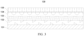
- FIG. 3 is a schematic diagram of an internal structure of a perovskite solar cell device 130 according to an embodiment of this application.
- the perovskite solar cell device 130 includes a transparent conductive electrode 131, a hole transport layer 132, a perovskite layer 133, an electron transmission layer 134, and a metal conductive layer 135 that are stacked in sequence.
- the hole transport layer 132 shown in FIG. 3 may be located at the electron transmission layer 134, and the electron transmission layer 134 is located at the hole transport layer 132.
- a material of the transparent conductive electrode 131 is selected from at least one of indium tin oxide and fluorine doped with tin dioxide.
- a material of the hole transport layer 132 is selected from at least one of poly(3,4-ethylenedioxythiophene), polystyrene sulfonate, poly[bis(4-phenyl)(2,4,6-trimethylphenyl)amine], CuSCN, NiO x , CuI, MoO x , 2,2',7,7'-tetrakis[N,N-bis(4-methoxyphenyl)amino]-9,9'-spirobifluorene, WO 3 , polyethoxyethyleneimine, polyethyleneimine, ZnO, TiO 2 , [6,6]-phenyl-C61-isobutyl butyrate, and SnO 2 .
- a material of the electron transmission layer 134 is selected from at least one of poly(3,4-ethylenedioxythiophene), polystyrene sulfonate, polytriarylamine , CuSCN, NiO x , CuI, MoO x , 2,2',7,7'-tetrakis[N,N-bis(4-methoxyphenyl)amino]-9,9'-spirobifluorene, WO 3 , polyethoxyethyleneimine, polyethyleneimine, ZnO, TiO 2 , [6,6]-phenyl-C61-isobutylbutyrate, and SnO 2 .
- a material of the metal conductive layer 135 is selected from at least one of Au, Ag, Cu, Al, Ni, Cr, Bi, Pt, Mg, and alloys thereof.
- a chemical formula of a perovskite material in the perovskite layer 133 is ABX 3 , where A includes an organic amine cation, B is a metal cation, and X is a halogen anion or SCN - .
- A may include at least one of CH 3 NH 3 + and HC(NH 2 ) 2 + .
- A may be CH 3 NH 3 + , HC(NH 2 ) 2 + or a mixture of the two in any ratio.
- A may further include a metal ion, for example, at least one of Cs + , Rb + , and K + .
- B may be at least one of Pb 2+ , Sn 2+ , and Ge 2+ .
- ABX 3 may be CH 3 NH 3 PbI 3 , CH 3 NH 3 SnI 3 , CH 3 NH 3 PbI 2 Cl, CH 3 NH 3 PbI 2 Br, or CH 3 NH 3 Pb(I 1-x Br x ) 3 (where 0 ⁇ x ⁇ 1), where
- CH 3 NH 3 + is abbreviated as MA +
- HC(NH 2 ) 2 + is abbreviated as FA +
- ABX 3 may further be:
- the inventors have found through research that the ammonia gas having the volume fraction of 10%-100% and the residual inert gas being contained in the sealed cavity 101 can effectively inhibit migration and decomposition of organic amine cations in the perovskite material, improve structural stability of the perovskite material, and improve thermal stability of the perovskite solar cell 100, thereby improving light conversion efficiency and service life of the perovskite solar cell.
- the volume fraction of the ammonia gas in the sealed cavity 101 is closely related to an effect of improving the structural stability of the perovskite material. On a condition that decomposition is inhibited to some extent, considering cost and safety, the volume fraction of the ammonia gas in the sealed cavity 101 may be within an appropriate range, such as 50%-70%.
- this application further shows a preparation method of the perovskite solar cell.
- the preparation method mainly includes the following steps.
- the preparation method mainly includes: preparing in sequence a transparent conductive electrode, one of a hole transport layer and an electron transmission layer, a perovskite layer, the other of the hole transport layer and the electron transmission layer, and a metal conductive layer on the transparent substrate.
- a material of the transparent conductive electrode is selected from at least one of indium tin oxide and fluorine doped with tin dioxide.
- a material of the hole transport layer and a material of the electron transmission layer are each independently selected from at least one of poly(3,4-ethylenedioxythiophene), polystyrene sulfonate, poly[bis(4-phenyl)(2,4,6-trimethylphenyl)amine], CuSCN, NiO x , CuI, MoOx, 2,2',7,7'-tetrakis[N,N-bis(4-methoxyphenyl)amino]-9,9'-spirobifluorene, WO 3 , polyethoxyethylene imine, polyethyleneimine, ZnO, TiO 2 , [6,6]-phenyl -C61- isobutyl butyrate, and SnO 2 .
- an optional formula of a material in the perovskite layer is ABX 3 , where A includes an organic amine cation, B is a metal cation, and X is a halogen anion or SCN .
- ABX 3 may be CH 3 NH 3 PbI 3 , CH 3 NH 3 SnI 3 , CH 3 NH 3 PbI 2 Cl, or CH 3 NH 3 PbI 2 Br, where CH 3 NH 3 + is abbreviated as MA + , and HC(NH 2 ) 2 + is abbreviated as FA + ; and ABX 3 may further be:
- a material of the metal conductive layer is selected from at least one of Au, Ag, Cu, Al, Ni, Cr, Bi, Pt, Mg, and alloys thereof.
- process parameters of step S1 may be as follows.
- the transparent substrate is etched with Zn powder and 1mol/L-2 mol/L hydrochloric acid, and then dried after washing.
- the transparent substrate is spin-coated with a TiO 2 precursor solution at a rate of 4000rpm-6500rpm, and kept at 120°C-150°C for 20min-25min; then the temperature is increased to 400°C-450°C and maintained at the temperature for 40min-45min; and then the transparent substrate is annealed at 120°C-150°C.
- the transparent substrate is spin-coated with a perovskite layer (which, for example, may be CH 3 NH 3 PnI 3 ) at a rate of 3000rpm-4500rpm, cured for 8h-10h, and then oxidized for 12h-13h in a low humidity drying tower.
- a perovskite layer which, for example, may be CH 3 NH 3 PnI 3
- the transparent substrate is vapor-deposited with a layer of electrode, such that a perovskite solar cell device is prepared.
- S2 In a preset atmosphere, package the perovskite solar cell device using a back plate, where the preset atmosphere contains ammonia gas having a volume fraction of 10%-100% and residual inert gas.
- the packaging includes that the perovskite solar cell device is packaged using a sealing material and the back plate.
- a method for packaging the perovskite solar cell device may be: The sealing material is applied at a periphery of the perovskite solar cell device and an entire back face of the perovskite solar cell device, and the back plate is attached to the back face of the perovskite solar cell device to implement sealing.
- the sealing material may alternatively be applied on the back plate before the back plate is attached to the back face of the perovskite solar cell device so that the sealing material is applied on the entire back face of the perovskite solar cell device.
- a method for packaging the perovskite solar cell device may be: The sealing material is applied at a periphery of the perovskite solar cell device, and the back plate is attached to the back face of the perovskite solar cell device to implement sealing.
- the sealing material may be applied on the back plate before the back plate is attached to the back face of the perovskite solar cell device.
- the sealing material may be a sealant
- the sealant may be an epoxy packaging sealant, for example, an epoxy AB sealant.
- the sealant may also be selected from at least one of an organic silicon packaging sealant, a polyurethane packaging sealant, a UV-light curing packaging sealant, ethylene-vinyl acetate copolymer, polyvinyl butyral, ethylene-octene copolymer, polyisobutylene, and a polyolefin packaging sealant.
- the sealing material may alternatively be another material that can seal the perovskite solar cell device.
- the sealing material may not be used to seal the perovskite solar cell device.
- the preset atmosphere includes the ammonia gas having the volume fraction of 10%-100%, the residual inert gas, and inevitable trace impurity gas.
- the volume fraction of the ammonia gas in the preset atmosphere may be 10%, 16%, 21%, 30%, 34%, 50%, 60%, 67%, 75%, 80%, 98%, 100%, or the like.
- the inert gas may be at least one of nitrogen, argon, helium, and neon.
- the inert gas is nitrogen.
- a process of step S2 may be as follows.
- a layer of a packaging sealant is applied at a periphery of the perovskite solar cell device and on a surface of the perovskite solar cell device, and the back plate is pressed onto the packaging sealant before the packaging sealant is cured.
- the preparation method of perovskite solar cell provided in this embodiment of this application has at least the following advantages.
- Packaging is performed in the preset atmosphere composed of the ammonia gas having the volume fraction of 10%-100% and the residual inert gas, so that the sealed cavity after packaging contains the ammonia gas having the volume fraction of 10%-100%.
- the foregoing configuration can effectively inhibit migration and decomposition of organic amine cations in the perovskite material and improve thermal stability of the perovskite solar cell device, thereby improving light conversion efficiency and service life of the perovskite solar cell.
- An embodiment of this application further provides an electric device, where the electric device includes the foregoing perovskite solar cell 100, and the perovskite solar cell 100 serves as a power source of the foregoing electric device for supplying power, or the perovskite solar cell 100 can be used as an energy storage unit of the foregoing electric device.
- the electric device may be a lighting element, a display element, an automobile, or the like.
- a perovskite solar cell was provided and mainly prepared through the following steps.
- Examples 2-28 and Comparative Examples 1-6 each provide a perovskite solar cell. For a preparation method thereof, refer to Example 1. These examples differ from Example 1 in an active substance at the perovskite layer in step (3) or the atmosphere in the glove box in step (6). Details are given in Table 1.
- a perovskite active material experiences thermal decomposition due to migration of organic cations, and when a specified amount of ammonia gas is present in the high temperature and high humidity environment, the thermal decomposition of the perovskite material is effectively inhibited, so that the thermal stability is improved.
- the more than 10vol% ammonia gas and the residual gas contained in the sealed cavity being selected as inert gas can effectively improve the light conversion efficiency service life of the perovskite cell.
- 50vol%-70vol% ammonia gas being contained in the sealed cavity of the perovskite cell is a preferred solution.
Landscapes
- Engineering & Computer Science (AREA)
- Physics & Mathematics (AREA)
- Electromagnetism (AREA)
- Manufacturing & Machinery (AREA)
- Chemical & Material Sciences (AREA)
- Materials Engineering (AREA)
- Power Engineering (AREA)
- Microelectronics & Electronic Packaging (AREA)
- Photovoltaic Devices (AREA)
Applications Claiming Priority (2)
| Application Number | Priority Date | Filing Date | Title |
|---|---|---|---|
| CN202110397769.1A CN115207219B (zh) | 2021-04-13 | 2021-04-13 | 钙钛矿太阳能电池及其制备方法、用电设备 |
| PCT/CN2022/081265 WO2022218089A1 (zh) | 2021-04-13 | 2022-03-16 | 钙钛矿太阳能电池及其制备方法、用电设备 |
Publications (3)
| Publication Number | Publication Date |
|---|---|
| EP4243103A1 true EP4243103A1 (de) | 2023-09-13 |
| EP4243103A4 EP4243103A4 (de) | 2024-06-12 |
| EP4243103B1 EP4243103B1 (de) | 2025-07-02 |
Family
ID=83570965
Family Applications (1)
| Application Number | Title | Priority Date | Filing Date |
|---|---|---|---|
| EP22787318.9A Active EP4243103B1 (de) | 2021-04-13 | 2022-03-16 | Perowskitsolarzelle und herstellungsverfahren dafür sowie elektrische vorrichtung |
Country Status (4)
| Country | Link |
|---|---|
| US (1) | US12382773B2 (de) |
| EP (1) | EP4243103B1 (de) |
| CN (1) | CN115207219B (de) |
| WO (1) | WO2022218089A1 (de) |
Families Citing this family (1)
| Publication number | Priority date | Publication date | Assignee | Title |
|---|---|---|---|---|
| CN115955892A (zh) * | 2023-02-10 | 2023-04-11 | 昆山协鑫光电材料有限公司 | 钙钛矿薄膜、无有机溶剂参与的钙钛矿薄膜制法及其应用 |
Family Cites Families (13)
| Publication number | Priority date | Publication date | Assignee | Title |
|---|---|---|---|---|
| US4555586A (en) * | 1984-08-06 | 1985-11-26 | Energy Conversion Devices, Inc. | Photovoltiac device having long term energy conversion stability and method of producing same |
| JP3940601B2 (ja) * | 2001-12-28 | 2007-07-04 | 医療法人 エヌアール日本生体咬合研究所 | 咬合補助装置 |
| JP2014143077A (ja) * | 2013-01-24 | 2014-08-07 | Rohm Co Ltd | 色素増感太陽電池およびその製造方法および電子機器 |
| CN106876586A (zh) * | 2015-11-24 | 2017-06-20 | 松下电器产业株式会社 | 太阳能电池 |
| US12046425B2 (en) * | 2017-04-14 | 2024-07-23 | Cubicpv Inc. | Photovoltaic device encapsulation |
| JPWO2019230534A1 (ja) * | 2018-06-01 | 2021-06-10 | コニカミノルタ株式会社 | 太陽電池及びその製造方法 |
| KR20200048037A (ko) * | 2018-10-29 | 2020-05-08 | 한국전력공사 | 페로브스카이트 태양전지 및 그 제조방법 |
| CN208923201U (zh) * | 2018-11-28 | 2019-05-31 | 中国华能集团有限公司 | 一种钙钛矿太阳能电池封装结构 |
| CN109411611B (zh) * | 2018-11-28 | 2024-07-02 | 中国华能集团有限公司 | 一种钙钛矿太阳能电池封装结构及封装方法 |
| KR20210007213A (ko) * | 2019-07-10 | 2021-01-20 | 주식회사 유니테스트 | 페로브스카이트 태양전지 모듈 및 이의 Encapsulation 방법 |
| CN112242490B (zh) * | 2019-07-16 | 2023-01-20 | 中国科学院青岛生物能源与过程研究所 | 一种甲脒基钙钛矿薄膜的后修复方法 |
| FR3109019A1 (fr) * | 2020-04-06 | 2021-10-08 | Elixens | Module photovoltaïque et procede de fabrication d’un tel module |
| CN112582549B (zh) * | 2020-12-28 | 2024-08-27 | 厦门大学 | 一种薄型无溶剂钙钛矿太阳能电池封装方法 |
-
2021
- 2021-04-13 CN CN202110397769.1A patent/CN115207219B/zh active Active
-
2022
- 2022-03-16 WO PCT/CN2022/081265 patent/WO2022218089A1/zh not_active Ceased
- 2022-03-16 EP EP22787318.9A patent/EP4243103B1/de active Active
-
2023
- 2023-06-07 US US18/330,624 patent/US12382773B2/en active Active
Also Published As
| Publication number | Publication date |
|---|---|
| US12382773B2 (en) | 2025-08-05 |
| EP4243103A4 (de) | 2024-06-12 |
| WO2022218089A1 (zh) | 2022-10-20 |
| EP4243103B1 (de) | 2025-07-02 |
| US20230320110A1 (en) | 2023-10-05 |
| CN115207219A (zh) | 2022-10-18 |
| CN115207219B (zh) | 2023-10-03 |
Similar Documents
| Publication | Publication Date | Title |
|---|---|---|
| JP2001185244A (ja) | 色素増感型太陽電池及び色素増感型太陽電池の作製方法並びに太陽電池モジュール | |
| KR100911381B1 (ko) | 다공성 박막의 제조 방법, 이를 이용하는 염료감응태양전지 및 그 제조 방법 | |
| CN114361347A (zh) | 一种钙钛矿太阳能电池组件及其制作方法 | |
| EP4633335A1 (de) | Verpackungsschichtstruktur eines perowskit-solarzellenmoduls und verpackungsverfahren dafür | |
| US12382773B2 (en) | Perovskite solar cell, preparation method thereof, and electric device | |
| CN216597635U (zh) | 钙钛矿电池组件的封装结构 | |
| CN212113753U (zh) | 一种含背电极的功能膜和薄膜光伏组件 | |
| CN115425154B (zh) | 一种钙钛矿太阳能电池组件的制备方法 | |
| CN115000307A (zh) | 钙钛矿太阳能电池及其封装结构组件 | |
| JP4651346B2 (ja) | 光電変換装置およびそれを用いた光発電装置 | |
| CN117355157A (zh) | 钙钛矿太阳电池组件 | |
| CN116615037A (zh) | 钙钛矿太阳能电池、制备方法、钙钛矿光伏组件及叠层电池 | |
| CN116801650A (zh) | 一种热蒸镀氧化物薄膜封装的钙钛矿太阳能电池 | |
| CN118804615A (zh) | 一种全钙钛矿二端子叠层太阳能电池及其制备方法 | |
| KR101462356B1 (ko) | 염료감응형 태양 전지 및 그 제조 방법 | |
| CN119653972B (zh) | 一种钙钛矿太阳能电池及其制备方法和包含其的钙钛矿光伏组件 | |
| CN222928760U (zh) | 钙钛矿光伏组件、用电装置、光伏系统以及发电装置 | |
| CN216054780U (zh) | 一种基于硅量子点集中器的四端叠层钙钛矿太阳能电池 | |
| CN222509923U (zh) | 一种采用真空封装的钙钛矿光充电器 | |
| CN222339893U (zh) | 一种太阳能光伏组件 | |
| CN222261080U (zh) | 太阳能电池封装结构 | |
| CN222655653U (zh) | 太阳能电池组件、光伏组件及用电装置 | |
| EP4560773A1 (de) | Perowskit-solarzelle, herstellungsverfahren dafür und elektrische vorrichtung | |
| CN223584658U (zh) | 太阳能电池组件、光伏设备、用电装置及发电装置 | |
| EP3220399B1 (de) | Elektrolyt für farbstoffsensibilisierte photoelektrische umwandlungselemente für niedrige luminanz und farbstoffsensibilisiertes photoelektrisches umwandlungselement für niedrige luminanz mit verwendung davon |
Legal Events
| Date | Code | Title | Description |
|---|---|---|---|
| STAA | Information on the status of an ep patent application or granted ep patent |
Free format text: STATUS: THE INTERNATIONAL PUBLICATION HAS BEEN MADE |
|
| PUAI | Public reference made under article 153(3) epc to a published international application that has entered the european phase |
Free format text: ORIGINAL CODE: 0009012 |
|
| STAA | Information on the status of an ep patent application or granted ep patent |
Free format text: STATUS: REQUEST FOR EXAMINATION WAS MADE |
|
| 17P | Request for examination filed |
Effective date: 20230607 |
|
| AK | Designated contracting states |
Kind code of ref document: A1 Designated state(s): AL AT BE BG CH CY CZ DE DK EE ES FI FR GB GR HR HU IE IS IT LI LT LU LV MC MK MT NL NO PL PT RO RS SE SI SK SM TR |
|
| REG | Reference to a national code |
Ref country code: DE Ref legal event code: R079 Free format text: PREVIOUS MAIN CLASS: H01L0051420000 Ipc: H10K0085500000 Ref country code: DE Ref legal event code: R079 Ref document number: 602022017038 Country of ref document: DE Free format text: PREVIOUS MAIN CLASS: H01L0051420000 Ipc: H10K0085500000 |
|
| A4 | Supplementary search report drawn up and despatched |
Effective date: 20240514 |
|
| RIC1 | Information provided on ipc code assigned before grant |
Ipc: H10K 30/50 20230101ALN20240508BHEP Ipc: H10K 71/40 20230101ALI20240508BHEP Ipc: H10K 30/88 20230101ALI20240508BHEP Ipc: H10K 85/50 20230101AFI20240508BHEP |
|
| DAV | Request for validation of the european patent (deleted) | ||
| DAX | Request for extension of the european patent (deleted) | ||
| RAP1 | Party data changed (applicant data changed or rights of an application transferred) |
Owner name: CONTEMPORARY AMPEREX TECHNOLOGY(HONG KONG) LIMITED |
|
| GRAP | Despatch of communication of intention to grant a patent |
Free format text: ORIGINAL CODE: EPIDOSNIGR1 |
|
| STAA | Information on the status of an ep patent application or granted ep patent |
Free format text: STATUS: GRANT OF PATENT IS INTENDED |
|
| RIC1 | Information provided on ipc code assigned before grant |
Ipc: H10K 30/40 20230101ALN20250327BHEP Ipc: H10K 30/50 20230101ALN20250327BHEP Ipc: H10K 71/40 20230101ALI20250327BHEP Ipc: H10K 30/88 20230101ALI20250327BHEP Ipc: H10K 85/50 20230101AFI20250327BHEP |
|
| INTG | Intention to grant announced |
Effective date: 20250408 |
|
| RIC1 | Information provided on ipc code assigned before grant |
Ipc: H10K 30/40 20230101ALN20250331BHEP Ipc: H10K 30/50 20230101ALN20250331BHEP Ipc: H10K 71/40 20230101ALI20250331BHEP Ipc: H10K 30/88 20230101ALI20250331BHEP Ipc: H10K 85/50 20230101AFI20250331BHEP |
|
| GRAS | Grant fee paid |
Free format text: ORIGINAL CODE: EPIDOSNIGR3 |
|
| GRAA | (expected) grant |
Free format text: ORIGINAL CODE: 0009210 |
|
| STAA | Information on the status of an ep patent application or granted ep patent |
Free format text: STATUS: THE PATENT HAS BEEN GRANTED |
|
| AK | Designated contracting states |
Kind code of ref document: B1 Designated state(s): AL AT BE BG CH CY CZ DE DK EE ES FI FR GB GR HR HU IE IS IT LI LT LU LV MC MK MT NL NO PL PT RO RS SE SI SK SM TR |
|
| REG | Reference to a national code |
Ref country code: GB Ref legal event code: FG4D |
|
| REG | Reference to a national code |
Ref country code: CH Ref legal event code: EP |
|
| P01 | Opt-out of the competence of the unified patent court (upc) registered |
Free format text: CASE NUMBER: APP_28859/2025 Effective date: 20250617 |
|
| REG | Reference to a national code |
Ref country code: DE Ref legal event code: R096 Ref document number: 602022017038 Country of ref document: DE |
|
| REG | Reference to a national code |
Ref country code: IE Ref legal event code: FG4D |
|
| REG | Reference to a national code |
Ref country code: NL Ref legal event code: MP Effective date: 20250702 |
|
| PG25 | Lapsed in a contracting state [announced via postgrant information from national office to epo] |
Ref country code: PT Free format text: LAPSE BECAUSE OF FAILURE TO SUBMIT A TRANSLATION OF THE DESCRIPTION OR TO PAY THE FEE WITHIN THE PRESCRIBED TIME-LIMIT Effective date: 20251103 |
|
| PG25 | Lapsed in a contracting state [announced via postgrant information from national office to epo] |
Ref country code: NL Free format text: LAPSE BECAUSE OF FAILURE TO SUBMIT A TRANSLATION OF THE DESCRIPTION OR TO PAY THE FEE WITHIN THE PRESCRIBED TIME-LIMIT Effective date: 20250702 |
|
| REG | Reference to a national code |
Ref country code: AT Ref legal event code: MK05 Ref document number: 1810858 Country of ref document: AT Kind code of ref document: T Effective date: 20250702 |
|
| PG25 | Lapsed in a contracting state [announced via postgrant information from national office to epo] |
Ref country code: IS Free format text: LAPSE BECAUSE OF FAILURE TO SUBMIT A TRANSLATION OF THE DESCRIPTION OR TO PAY THE FEE WITHIN THE PRESCRIBED TIME-LIMIT Effective date: 20251102 |
|
| PG25 | Lapsed in a contracting state [announced via postgrant information from national office to epo] |
Ref country code: NO Free format text: LAPSE BECAUSE OF FAILURE TO SUBMIT A TRANSLATION OF THE DESCRIPTION OR TO PAY THE FEE WITHIN THE PRESCRIBED TIME-LIMIT Effective date: 20251002 |
|
| REG | Reference to a national code |
Ref country code: LT Ref legal event code: MG9D |
|
| PG25 | Lapsed in a contracting state [announced via postgrant information from national office to epo] |
Ref country code: AT Free format text: LAPSE BECAUSE OF FAILURE TO SUBMIT A TRANSLATION OF THE DESCRIPTION OR TO PAY THE FEE WITHIN THE PRESCRIBED TIME-LIMIT Effective date: 20250702 |
|
| PG25 | Lapsed in a contracting state [announced via postgrant information from national office to epo] |
Ref country code: FI Free format text: LAPSE BECAUSE OF FAILURE TO SUBMIT A TRANSLATION OF THE DESCRIPTION OR TO PAY THE FEE WITHIN THE PRESCRIBED TIME-LIMIT Effective date: 20250702 |
|
| PG25 | Lapsed in a contracting state [announced via postgrant information from national office to epo] |
Ref country code: HR Free format text: LAPSE BECAUSE OF FAILURE TO SUBMIT A TRANSLATION OF THE DESCRIPTION OR TO PAY THE FEE WITHIN THE PRESCRIBED TIME-LIMIT Effective date: 20250702 |
|
| PG25 | Lapsed in a contracting state [announced via postgrant information from national office to epo] |
Ref country code: GR Free format text: LAPSE BECAUSE OF FAILURE TO SUBMIT A TRANSLATION OF THE DESCRIPTION OR TO PAY THE FEE WITHIN THE PRESCRIBED TIME-LIMIT Effective date: 20251003 |
|
| PG25 | Lapsed in a contracting state [announced via postgrant information from national office to epo] |
Ref country code: SE Free format text: LAPSE BECAUSE OF FAILURE TO SUBMIT A TRANSLATION OF THE DESCRIPTION OR TO PAY THE FEE WITHIN THE PRESCRIBED TIME-LIMIT Effective date: 20250702 Ref country code: CZ Free format text: LAPSE BECAUSE OF FAILURE TO SUBMIT A TRANSLATION OF THE DESCRIPTION OR TO PAY THE FEE WITHIN THE PRESCRIBED TIME-LIMIT Effective date: 20250702 |
|
| PG25 | Lapsed in a contracting state [announced via postgrant information from national office to epo] |
Ref country code: LV Free format text: LAPSE BECAUSE OF FAILURE TO SUBMIT A TRANSLATION OF THE DESCRIPTION OR TO PAY THE FEE WITHIN THE PRESCRIBED TIME-LIMIT Effective date: 20250702 |
|
| PG25 | Lapsed in a contracting state [announced via postgrant information from national office to epo] |
Ref country code: BG Free format text: LAPSE BECAUSE OF FAILURE TO SUBMIT A TRANSLATION OF THE DESCRIPTION OR TO PAY THE FEE WITHIN THE PRESCRIBED TIME-LIMIT Effective date: 20250702 Ref country code: PL Free format text: LAPSE BECAUSE OF FAILURE TO SUBMIT A TRANSLATION OF THE DESCRIPTION OR TO PAY THE FEE WITHIN THE PRESCRIBED TIME-LIMIT Effective date: 20250702 |
|
| PG25 | Lapsed in a contracting state [announced via postgrant information from national office to epo] |
Ref country code: RS Free format text: LAPSE BECAUSE OF FAILURE TO SUBMIT A TRANSLATION OF THE DESCRIPTION OR TO PAY THE FEE WITHIN THE PRESCRIBED TIME-LIMIT Effective date: 20251002 |
|
| PG25 | Lapsed in a contracting state [announced via postgrant information from national office to epo] |
Ref country code: ES Free format text: LAPSE BECAUSE OF FAILURE TO SUBMIT A TRANSLATION OF THE DESCRIPTION OR TO PAY THE FEE WITHIN THE PRESCRIBED TIME-LIMIT Effective date: 20250702 |