EP4243103A1 - Perovskite solar cell and preparation method therefor, and electrical device - Google Patents
Perovskite solar cell and preparation method therefor, and electrical device Download PDFInfo
- Publication number
- EP4243103A1 EP4243103A1 EP22787318.9A EP22787318A EP4243103A1 EP 4243103 A1 EP4243103 A1 EP 4243103A1 EP 22787318 A EP22787318 A EP 22787318A EP 4243103 A1 EP4243103 A1 EP 4243103A1
- Authority
- EP
- European Patent Office
- Prior art keywords
- solar cell
- perovskite solar
- cell device
- sealant
- back plate
- Prior art date
- Legal status (The legal status is an assumption and is not a legal conclusion. Google has not performed a legal analysis and makes no representation as to the accuracy of the status listed.)
- Granted
Links
Images

Classifications
-
- H—ELECTRICITY
- H10—SEMICONDUCTOR DEVICES; ELECTRIC SOLID-STATE DEVICES NOT OTHERWISE PROVIDED FOR
- H10K—ORGANIC ELECTRIC SOLID-STATE DEVICES
- H10K30/00—Organic devices sensitive to infrared radiation, light, electromagnetic radiation of shorter wavelength or corpuscular radiation
- H10K30/40—Organic devices sensitive to infrared radiation, light, electromagnetic radiation of shorter wavelength or corpuscular radiation comprising a p-i-n structure, e.g. having a perovskite absorber between p-type and n-type charge transport layers
-
- H—ELECTRICITY
- H01—ELECTRIC ELEMENTS
- H01G—CAPACITORS; CAPACITORS, RECTIFIERS, DETECTORS, SWITCHING DEVICES, LIGHT-SENSITIVE OR TEMPERATURE-SENSITIVE DEVICES OF THE ELECTROLYTIC TYPE
- H01G9/00—Electrolytic capacitors, rectifiers, detectors, switching devices, light-sensitive or temperature-sensitive devices; Processes of their manufacture
- H01G9/0029—Processes of manufacture
-
- H—ELECTRICITY
- H01—ELECTRIC ELEMENTS
- H01G—CAPACITORS; CAPACITORS, RECTIFIERS, DETECTORS, SWITCHING DEVICES, LIGHT-SENSITIVE OR TEMPERATURE-SENSITIVE DEVICES OF THE ELECTROLYTIC TYPE
- H01G9/00—Electrolytic capacitors, rectifiers, detectors, switching devices, light-sensitive or temperature-sensitive devices; Processes of their manufacture
- H01G9/20—Light-sensitive devices
-
- H—ELECTRICITY
- H10—SEMICONDUCTOR DEVICES; ELECTRIC SOLID-STATE DEVICES NOT OTHERWISE PROVIDED FOR
- H10K—ORGANIC ELECTRIC SOLID-STATE DEVICES
- H10K30/00—Organic devices sensitive to infrared radiation, light, electromagnetic radiation of shorter wavelength or corpuscular radiation
- H10K30/50—Photovoltaic [PV] devices
-
- H—ELECTRICITY
- H10—SEMICONDUCTOR DEVICES; ELECTRIC SOLID-STATE DEVICES NOT OTHERWISE PROVIDED FOR
- H10K—ORGANIC ELECTRIC SOLID-STATE DEVICES
- H10K30/00—Organic devices sensitive to infrared radiation, light, electromagnetic radiation of shorter wavelength or corpuscular radiation
- H10K30/80—Constructional details
- H10K30/88—Passivation; Containers; Encapsulations
-
- H—ELECTRICITY
- H10—SEMICONDUCTOR DEVICES; ELECTRIC SOLID-STATE DEVICES NOT OTHERWISE PROVIDED FOR
- H10K—ORGANIC ELECTRIC SOLID-STATE DEVICES
- H10K71/00—Manufacture or treatment specially adapted for the organic devices covered by this subclass
- H10K71/10—Deposition of organic active material
- H10K71/12—Deposition of organic active material using liquid deposition, e.g. spin coating
-
- H—ELECTRICITY
- H10—SEMICONDUCTOR DEVICES; ELECTRIC SOLID-STATE DEVICES NOT OTHERWISE PROVIDED FOR
- H10K—ORGANIC ELECTRIC SOLID-STATE DEVICES
- H10K71/00—Manufacture or treatment specially adapted for the organic devices covered by this subclass
- H10K71/40—Thermal treatment, e.g. annealing in the presence of a solvent vapour
-
- H—ELECTRICITY
- H10—SEMICONDUCTOR DEVICES; ELECTRIC SOLID-STATE DEVICES NOT OTHERWISE PROVIDED FOR
- H10K—ORGANIC ELECTRIC SOLID-STATE DEVICES
- H10K71/00—Manufacture or treatment specially adapted for the organic devices covered by this subclass
- H10K71/811—Controlling the atmosphere during processing
-
- H—ELECTRICITY
- H10—SEMICONDUCTOR DEVICES; ELECTRIC SOLID-STATE DEVICES NOT OTHERWISE PROVIDED FOR
- H10K—ORGANIC ELECTRIC SOLID-STATE DEVICES
- H10K85/00—Organic materials used in the body or electrodes of devices covered by this subclass
- H10K85/50—Organic perovskites; Hybrid organic-inorganic perovskites [HOIP], e.g. CH3NH3PbI3
-
- Y—GENERAL TAGGING OF NEW TECHNOLOGICAL DEVELOPMENTS; GENERAL TAGGING OF CROSS-SECTIONAL TECHNOLOGIES SPANNING OVER SEVERAL SECTIONS OF THE IPC; TECHNICAL SUBJECTS COVERED BY FORMER USPC CROSS-REFERENCE ART COLLECTIONS [XRACs] AND DIGESTS
- Y02—TECHNOLOGIES OR APPLICATIONS FOR MITIGATION OR ADAPTATION AGAINST CLIMATE CHANGE
- Y02E—REDUCTION OF GREENHOUSE GAS [GHG] EMISSIONS, RELATED TO ENERGY GENERATION, TRANSMISSION OR DISTRIBUTION
- Y02E10/00—Energy generation through renewable energy sources
- Y02E10/50—Photovoltaic [PV] energy
- Y02E10/549—Organic PV cells
Definitions
- This application relates to the field of battery technologies, and in particular, to a perovskite solar cell, a preparation method therefor, and an electrical device.
- perovskite materials are easy to decompose under actions of light, heat, water, and oxygen, reducing photoelectric conversion efficiency of perovskite solar cells. Therefore, it is necessary to ensure that a perovskite solar cell device is prepared with good sealing performance.
- the perovskite battery device with only good sealing performance ensured during packaging has a limited effect on prolonging service life of a perovskite solar cell.
- Embodiments of this application are intended to provide a perovskite solar cell, a preparation method thereof, and an electric device, so as to prolong service life of the perovskite solar cell.
- a first aspect of this application provides a perovskite solar cell, including:
- the 10%-100% ammonia gas and the residual inert gas are contained in a structure of the perovskite solar cell containing the organic amine cation, which can effectively inhibit migration and decomposition of organic amine cations in the perovskite material and improves thermal stability of the perovskite solar cell device, thereby improving light conversion efficiency and service life of the perovskite solar cell.
- A includes at least one of CH 3 NH 3 + and HC(NH 2 ) 2 + .
- B is at least one of Pb 2+ , Sn 2+ , and Ge 2+ .
- A further includes at least one of Cs + , Rb + , and K + .
- the inert gas includes at least one of nitrogen, argon, helium, and neon.
- the volume fraction of the ammonia gas in the sealed cavity is 30%-90%.
- the volume fraction of the ammonia gas in the sealed cavity is 50%-70%.
- the volume fraction of the ammonia gas being controlled within the above ranges in the sealed cavity can ensure various advantages such as low production costs, high light conversion efficiency of the solar cell, and operation safety.
- the perovskite solar cell further includes a sealing element, where the sealing element connects the transparent substrate and the back plate to form the sealed cavity.
- the sealing element is a sealant.
- the sealant is around a periphery of the perovskite solar cell device, and the back plate is fastened to the perovskite solar cell device using the sealant.
- the sealant is further located on at least part of a surface or the entire surface on a side of the back plate facing toward the perovskite solar cell device.
- a material of the transparent substrate is glass or polyethylene terephthalate.
- a material of the back plate is glass or polyethylene terephthalate.
- a second aspect of this application provides a preparation method of perovskite solar cell, including:
- the perovskite solar cell device is packaged in the preset atmosphere containing the ammonia gas having the volume fraction of 10%-100% and the residual inert gas, so that the perovskite solar cell device is located in the above preset atmosphere; and the present atmosphere can inhibit migration and decomposition of organic amine cations in the perovskite material containing the organic amine cation.
- A in ABX 3 , includes at least one of CH 3 NH 3 + and HC(NH 2 ) 2 + .
- B is at least one of Pb 2+ , Sn 2+ , and Ge 2+ .
- A further includes at least one of Cs + , Rb + , and K + .
- the inert gas includes at least one of nitrogen, argon, helium, and neon.
- the volume fraction of the ammonia gas in the preset atmosphere is 30%-90%.
- the volume fraction of the ammonia gas in the preset atmosphere is 50%-70%.
- Packaging in the above preset atmosphere can allow the preset atmosphere to be packaged inside the perovskite solar cell device, which reduces costs in a manufacturing process when the efficiency and service life of the battery are increased.
- a sealing element is used for packaging.
- the sealing element is a sealant.
- the sealant is applied at a periphery of the perovskite solar cell device, and the back plate is fastened to the perovskite solar cell device using the sealant.
- the sealant is further applied on at least part of a surface or the entire surface on a side of the back plate facing toward the perovskite solar cell device.
- a third aspect of this application provides an electric device, where the electric device includes the perovskite solar cell according to the first aspect, and the perovskite solar cell serves as a power source or an energy storage unit of the electric device.
- Embodiments where specific conditions are not specified, are implemented in accordance with general conditions or those recommended by a manufacturer.
- the reagents or instruments used are all conventional products that can be purchased on the market if no manufacturer is indicated.
- FIG. 1 is a schematic cross-sectional diagram of a perovskite solar cell 100 according to an embodiment of this application.
- this embodiment provides a perovskite solar cell 100, where the perovskite solar cell 100 mainly includes a back plate 110, a transparent substrate 120, and a perovskite solar cell device 130.
- a sealed cavity 101 is formed between the back plate 110 and the transparent substrate 120, and the perovskite solar cell device 130 is located in the sealed cavity 101.
- the perovskite solar cell 100 further includes a sealing element 140, where the sealing element 140 is located between the back plate 110 and the transparent substrate 120, and the back plate 110, the transparent substrate 120, and the sealing element jointly enclose the sealed cavity 101.
- a side of the transparent substrate 120 is provided with a positive electrode leading-out terminal 121 and a negative electrode leading-out terminal 122; a front face of the perovskite solar cell device 130 is connected to the transparent substrate 120; a positive electrode of the perovskite solar cell device 130 is electrically connected to the positive electrode leading-out terminal 121 and a negative electrode of the perovskite solar cell device 130 is connected to the negative electrode leading-out terminal 122; and a back face of the perovskite solar cell device 130 is connected to the back plate 110, the sealing element 140 is located between the back face of the perovskite solar cell device 130 and the back plate 110, and the sealing element 140 seals the perovskite solar cell device 130.
- a material of the transparent substrate 120 is glass.
- a material of the transparent substrate 120 may be another transparent material such as polyethylene terephthalate.
- a material of the back plate 110 is polyethylene terephthalate.
- a material of the back plate 110 may alternatively be glass or another material.
- the sealing element 140 is a sealant; and for example, the sealant may seal the perovskite solar cell device 130 through the following implementations.
- the sealant is applied on an entire surface of the perovskite solar cell device 130 facing away from the transparent substrate 120 and at a periphery of the perovskite solar cell device 130, and the back plate 110 is attached to the sealant to seal the perovskite solar cell device 130; or alternatively, the sealant is applied on a surface of the back plate 110 facing toward the perovskite solar cell device 130, and the back plate 110 is attached to the sealant to seal the perovskite solar cell device 130; and the sealed cavity 101 is present between the sealant and the perovskite solar cell device 130.
- the sealed cavity 101 may be provided in a quantity of one or more, and a plurality of sealed cavities 101 may communicate with each other or not.
- the sealant being applied on the entire surface of the perovskite solar cell device 130 facing away from the transparent substrate 120 helps improve mechanical property of the perovskite solar cell 100, increasing firmness and stability of a packaging structure of the perovskite solar cell 100.
- FIG. 2 is a schematic cross-sectional diagram of a perovskite solar cell 100 according to an embodiment of this application.
- the sealant is around a periphery of the perovskite solar cell device 130 and on a partial surface of the perovskite solar cell device 130 facing away from the transparent substrate 120.
- the sealant may seal the perovskite solar cell device 130 in the following manners.
- the sealant is applied at the periphery of the perovskite solar cell device 130, and the back plate 110 is attached to the sealant to seal the perovskite solar cell device 130.
- the sealant is applied at a periphery of the back plate 110 facing toward the perovskite solar cell device 130, and the back plate 110 is attached to the sealant to seal the perovskite solar cell device 130.
- the sealed cavity 101 is present between the perovskite solar cell device 130 and the back plate 110; or in some embodiments, due to an uneven surface of the perovskite solar cell device 130 or other reasons, there may alternatively be at least one sealed cavity 101 between the perovskite solar cell device 130 and the sealant.
- the above two examples are made with respect to sealing of the perovskite solar cell device 130 using the sealant.
- the sealant may seal the perovskite solar cell device 130 in another manner.
- the sealant is applied at the periphery of the back plate 110 facing toward the perovskite solar cell device 130 and on an entire surface of the back plate 110, and the back plate 110 is attached to the sealant to seal the perovskite solar cell device 130.
- the sealed cavity 101 formed may be located between the sealant and the perovskite solar cell device 130, or may alternatively be located between the perovskite solar cell device 130 and the back plate 110; or the sealed cavity 101 is provided at both the above positions.
- a shape and a quantity of the sealed cavity 101 and whether a plurality of sealed cavities 101 communicate with each other are not limited in this application.
- the sealed cavity 101 accounting for a large volume of the entire perovskite solar cell 100 is merely intended for better identifying the sealed cavity 101 in the figure. This does not mean that the volume accounted by the sealed cavity 101 of the entire perovskite solar cell 100 is as shown in FIG. 1 or FIG. 2 . It should be noted that the volume occupied by the sealed cavity 101 of the entire perovskite solar cell 100 is not limited in the embodiments of this application. During actual production, the sealed cavity 101 may be a cavity deliberately formed during packaging, or may alternatively be a cavity inevitably formed during packaging; or may include both the above cases.
- the sealant is selected from at least one of an epoxy packaging sealant, an organic silicon packaging sealant, a polyurethane packaging sealant, a UV-light curing packaging sealant, ethylene-vinyl acetate copolymer, polyvinyl butyral, ethylene-octene copolymer, polyisobutylene, and a polyolefin packaging sealant.
- the sealant is an epoxy packaging sealant, for example, an epoxy AB sealant including sealant A and sealant B of which a mass ratio is 2:(0.5-1.5), and the mass ratio of sealant A to sealant B may be, for example, 2:0.5, 2:0.8, 2:1, 2:1.2 or 2:1.5.
- the sealing element 140 may not be limited to the sealant.
- another sealing part is used to seal the perovskite solar cell device 130; or no sealing element 140 is used to seal the perovskite solar cell device 130, and the perovskite solar cell device 130 is directly sealed by the transparent substrate 120 and the back plate 110.
- the sealed cavity 101 contains ammonia gas having a volume fraction of 10%-100% and residual inert gas.
- gases in the sealed cavity 101 include the ammonia gas having the volume fraction of 10%-100% and the residual inert gas.
- the volume fraction of the ammonia gas in the sealed cavity 101 may be 50%-90%, 30%-70%, 60%-80%, or the like.
- the volume fraction of the ammonia gas in the sealed cavity 101 may be 10%, 16%, 21%, 30%, 34%, 50%, 60%, 67%, 75%, 80%, 98%, 100%, or the like.
- the inert gas may be at least one of nitrogen, argon, helium, and neon.
- the inert gas is nitrogen.
- the sealed cavity 101 may further include inevitable trace impurity gas during actual production (generally, a volume fraction of the trace impurity gas is less than 1%).
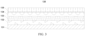
- FIG. 3 is a schematic diagram of an internal structure of a perovskite solar cell device 130 according to an embodiment of this application.
- the perovskite solar cell device 130 includes a transparent conductive electrode 131, a hole transport layer 132, a perovskite layer 133, an electron transmission layer 134, and a metal conductive layer 135 that are stacked in sequence.
- the hole transport layer 132 shown in FIG. 3 may be located at the electron transmission layer 134, and the electron transmission layer 134 is located at the hole transport layer 132.
- a material of the transparent conductive electrode 131 is selected from at least one of indium tin oxide and fluorine doped with tin dioxide.
- a material of the hole transport layer 132 is selected from at least one of poly(3,4-ethylenedioxythiophene), polystyrene sulfonate, poly[bis(4-phenyl)(2,4,6-trimethylphenyl)amine], CuSCN, NiO x , CuI, MoO x , 2,2',7,7'-tetrakis[N,N-bis(4-methoxyphenyl)amino]-9,9'-spirobifluorene, WO 3 , polyethoxyethyleneimine, polyethyleneimine, ZnO, TiO 2 , [6,6]-phenyl-C61-isobutyl butyrate, and SnO 2 .
- a material of the electron transmission layer 134 is selected from at least one of poly(3,4-ethylenedioxythiophene), polystyrene sulfonate, polytriarylamine , CuSCN, NiO x , CuI, MoO x , 2,2',7,7'-tetrakis[N,N-bis(4-methoxyphenyl)amino]-9,9'-spirobifluorene, WO 3 , polyethoxyethyleneimine, polyethyleneimine, ZnO, TiO 2 , [6,6]-phenyl-C61-isobutylbutyrate, and SnO 2 .
- a material of the metal conductive layer 135 is selected from at least one of Au, Ag, Cu, Al, Ni, Cr, Bi, Pt, Mg, and alloys thereof.
- a chemical formula of a perovskite material in the perovskite layer 133 is ABX 3 , where A includes an organic amine cation, B is a metal cation, and X is a halogen anion or SCN - .
- A may include at least one of CH 3 NH 3 + and HC(NH 2 ) 2 + .
- A may be CH 3 NH 3 + , HC(NH 2 ) 2 + or a mixture of the two in any ratio.
- A may further include a metal ion, for example, at least one of Cs + , Rb + , and K + .
- B may be at least one of Pb 2+ , Sn 2+ , and Ge 2+ .
- ABX 3 may be CH 3 NH 3 PbI 3 , CH 3 NH 3 SnI 3 , CH 3 NH 3 PbI 2 Cl, CH 3 NH 3 PbI 2 Br, or CH 3 NH 3 Pb(I 1-x Br x ) 3 (where 0 ⁇ x ⁇ 1), where
- CH 3 NH 3 + is abbreviated as MA +
- HC(NH 2 ) 2 + is abbreviated as FA +
- ABX 3 may further be:
- the inventors have found through research that the ammonia gas having the volume fraction of 10%-100% and the residual inert gas being contained in the sealed cavity 101 can effectively inhibit migration and decomposition of organic amine cations in the perovskite material, improve structural stability of the perovskite material, and improve thermal stability of the perovskite solar cell 100, thereby improving light conversion efficiency and service life of the perovskite solar cell.
- the volume fraction of the ammonia gas in the sealed cavity 101 is closely related to an effect of improving the structural stability of the perovskite material. On a condition that decomposition is inhibited to some extent, considering cost and safety, the volume fraction of the ammonia gas in the sealed cavity 101 may be within an appropriate range, such as 50%-70%.
- this application further shows a preparation method of the perovskite solar cell.
- the preparation method mainly includes the following steps.
- the preparation method mainly includes: preparing in sequence a transparent conductive electrode, one of a hole transport layer and an electron transmission layer, a perovskite layer, the other of the hole transport layer and the electron transmission layer, and a metal conductive layer on the transparent substrate.
- a material of the transparent conductive electrode is selected from at least one of indium tin oxide and fluorine doped with tin dioxide.
- a material of the hole transport layer and a material of the electron transmission layer are each independently selected from at least one of poly(3,4-ethylenedioxythiophene), polystyrene sulfonate, poly[bis(4-phenyl)(2,4,6-trimethylphenyl)amine], CuSCN, NiO x , CuI, MoOx, 2,2',7,7'-tetrakis[N,N-bis(4-methoxyphenyl)amino]-9,9'-spirobifluorene, WO 3 , polyethoxyethylene imine, polyethyleneimine, ZnO, TiO 2 , [6,6]-phenyl -C61- isobutyl butyrate, and SnO 2 .
- an optional formula of a material in the perovskite layer is ABX 3 , where A includes an organic amine cation, B is a metal cation, and X is a halogen anion or SCN .
- ABX 3 may be CH 3 NH 3 PbI 3 , CH 3 NH 3 SnI 3 , CH 3 NH 3 PbI 2 Cl, or CH 3 NH 3 PbI 2 Br, where CH 3 NH 3 + is abbreviated as MA + , and HC(NH 2 ) 2 + is abbreviated as FA + ; and ABX 3 may further be:
- a material of the metal conductive layer is selected from at least one of Au, Ag, Cu, Al, Ni, Cr, Bi, Pt, Mg, and alloys thereof.
- process parameters of step S1 may be as follows.
- the transparent substrate is etched with Zn powder and 1mol/L-2 mol/L hydrochloric acid, and then dried after washing.
- the transparent substrate is spin-coated with a TiO 2 precursor solution at a rate of 4000rpm-6500rpm, and kept at 120°C-150°C for 20min-25min; then the temperature is increased to 400°C-450°C and maintained at the temperature for 40min-45min; and then the transparent substrate is annealed at 120°C-150°C.
- the transparent substrate is spin-coated with a perovskite layer (which, for example, may be CH 3 NH 3 PnI 3 ) at a rate of 3000rpm-4500rpm, cured for 8h-10h, and then oxidized for 12h-13h in a low humidity drying tower.
- a perovskite layer which, for example, may be CH 3 NH 3 PnI 3
- the transparent substrate is vapor-deposited with a layer of electrode, such that a perovskite solar cell device is prepared.
- S2 In a preset atmosphere, package the perovskite solar cell device using a back plate, where the preset atmosphere contains ammonia gas having a volume fraction of 10%-100% and residual inert gas.
- the packaging includes that the perovskite solar cell device is packaged using a sealing material and the back plate.
- a method for packaging the perovskite solar cell device may be: The sealing material is applied at a periphery of the perovskite solar cell device and an entire back face of the perovskite solar cell device, and the back plate is attached to the back face of the perovskite solar cell device to implement sealing.
- the sealing material may alternatively be applied on the back plate before the back plate is attached to the back face of the perovskite solar cell device so that the sealing material is applied on the entire back face of the perovskite solar cell device.
- a method for packaging the perovskite solar cell device may be: The sealing material is applied at a periphery of the perovskite solar cell device, and the back plate is attached to the back face of the perovskite solar cell device to implement sealing.
- the sealing material may be applied on the back plate before the back plate is attached to the back face of the perovskite solar cell device.
- the sealing material may be a sealant
- the sealant may be an epoxy packaging sealant, for example, an epoxy AB sealant.
- the sealant may also be selected from at least one of an organic silicon packaging sealant, a polyurethane packaging sealant, a UV-light curing packaging sealant, ethylene-vinyl acetate copolymer, polyvinyl butyral, ethylene-octene copolymer, polyisobutylene, and a polyolefin packaging sealant.
- the sealing material may alternatively be another material that can seal the perovskite solar cell device.
- the sealing material may not be used to seal the perovskite solar cell device.
- the preset atmosphere includes the ammonia gas having the volume fraction of 10%-100%, the residual inert gas, and inevitable trace impurity gas.
- the volume fraction of the ammonia gas in the preset atmosphere may be 10%, 16%, 21%, 30%, 34%, 50%, 60%, 67%, 75%, 80%, 98%, 100%, or the like.
- the inert gas may be at least one of nitrogen, argon, helium, and neon.
- the inert gas is nitrogen.
- a process of step S2 may be as follows.
- a layer of a packaging sealant is applied at a periphery of the perovskite solar cell device and on a surface of the perovskite solar cell device, and the back plate is pressed onto the packaging sealant before the packaging sealant is cured.
- the preparation method of perovskite solar cell provided in this embodiment of this application has at least the following advantages.
- Packaging is performed in the preset atmosphere composed of the ammonia gas having the volume fraction of 10%-100% and the residual inert gas, so that the sealed cavity after packaging contains the ammonia gas having the volume fraction of 10%-100%.
- the foregoing configuration can effectively inhibit migration and decomposition of organic amine cations in the perovskite material and improve thermal stability of the perovskite solar cell device, thereby improving light conversion efficiency and service life of the perovskite solar cell.
- An embodiment of this application further provides an electric device, where the electric device includes the foregoing perovskite solar cell 100, and the perovskite solar cell 100 serves as a power source of the foregoing electric device for supplying power, or the perovskite solar cell 100 can be used as an energy storage unit of the foregoing electric device.
- the electric device may be a lighting element, a display element, an automobile, or the like.
- a perovskite solar cell was provided and mainly prepared through the following steps.
- Examples 2-28 and Comparative Examples 1-6 each provide a perovskite solar cell. For a preparation method thereof, refer to Example 1. These examples differ from Example 1 in an active substance at the perovskite layer in step (3) or the atmosphere in the glove box in step (6). Details are given in Table 1.
- a perovskite active material experiences thermal decomposition due to migration of organic cations, and when a specified amount of ammonia gas is present in the high temperature and high humidity environment, the thermal decomposition of the perovskite material is effectively inhibited, so that the thermal stability is improved.
- the more than 10vol% ammonia gas and the residual gas contained in the sealed cavity being selected as inert gas can effectively improve the light conversion efficiency service life of the perovskite cell.
- 50vol%-70vol% ammonia gas being contained in the sealed cavity of the perovskite cell is a preferred solution.
Landscapes
- Engineering & Computer Science (AREA)
- Physics & Mathematics (AREA)
- Electromagnetism (AREA)
- Manufacturing & Machinery (AREA)
- Chemical & Material Sciences (AREA)
- Materials Engineering (AREA)
- Power Engineering (AREA)
- Microelectronics & Electronic Packaging (AREA)
- Photovoltaic Devices (AREA)
Abstract
Description
- This application claims priority to
Chinese patent application No. 2021103977691, filed on April 13, 2021 - This application relates to the field of battery technologies, and in particular, to a perovskite solar cell, a preparation method therefor, and an electrical device.
- With poor stability, perovskite materials are easy to decompose under actions of light, heat, water, and oxygen, reducing photoelectric conversion efficiency of perovskite solar cells. Therefore, it is necessary to ensure that a perovskite solar cell device is prepared with good sealing performance.
- However, the perovskite battery device with only good sealing performance ensured during packaging has a limited effect on prolonging service life of a perovskite solar cell.
- Embodiments of this application are intended to provide a perovskite solar cell, a preparation method thereof, and an electric device, so as to prolong service life of the perovskite solar cell.
- A first aspect of this application provides a perovskite solar cell, including:
- a back plate;
- a transparent substrate, where a sealed cavity is formed between the transparent substrate and the back plate; and
- a perovskite solar cell device, where the perovskite solar cell device is located in the sealed cavity; where
- the sealed cavity contains ammonia gas having a volume fraction of 10%-100% and residual inert gas, and a chemical formula of a perovskite material of the perovskite solar cell device is ABX3, where A includes an organic amine cation, B is a metal cation, and X is a halogen anion or SCN-.
- In this application, the 10%-100% ammonia gas and the residual inert gas are contained in a structure of the perovskite solar cell containing the organic amine cation, which can effectively inhibit migration and decomposition of organic amine cations in the perovskite material and improves thermal stability of the perovskite solar cell device, thereby improving light conversion efficiency and service life of the perovskite solar cell.
- In some embodiments of the first aspect of this application, A includes at least one of CH3NH3 + and HC(NH2)2 +.
- Optionally, in ABX3, B is at least one of Pb2+, Sn2+, and Ge2+.
- In some embodiments of the first aspect of this application, in ABX3, A further includes at least one of Cs+, Rb+, and K+.
- In some embodiments of the first aspect of this application, the inert gas includes at least one of nitrogen, argon, helium, and neon.
- Optionally, the volume fraction of the ammonia gas in the sealed cavity is 30%-90%.
- Optionally, the volume fraction of the ammonia gas in the sealed cavity is 50%-70%.
- In this application, the volume fraction of the ammonia gas being controlled within the above ranges in the sealed cavity can ensure various advantages such as low production costs, high light conversion efficiency of the solar cell, and operation safety.
- In some embodiments of the first aspect of this application, the perovskite solar cell further includes a sealing element, where the sealing element connects the transparent substrate and the back plate to form the sealed cavity.
- Optionally, the sealing element is a sealant.
- Optionally, the sealant is around a periphery of the perovskite solar cell device, and the back plate is fastened to the perovskite solar cell device using the sealant.
- Optionally, the sealant is further located on at least part of a surface or the entire surface on a side of the back plate facing toward the perovskite solar cell device.
- In some embodiments of the first aspect of this application, a material of the transparent substrate is glass or polyethylene terephthalate.
- Optionally, a material of the back plate is glass or polyethylene terephthalate.
- A second aspect of this application provides a preparation method of perovskite solar cell, including:
- providing a transparent substrate and a back plate; and
- in a preset atmosphere, packaging a perovskite solar cell device between the transparent substrate and the back plate; where
- the preset atmosphere contains ammonia gas having a volume fraction of 10%-100% and residual inert gas, and a chemical formula of a perovskite material of the perovskite solar cell device is ABX3, where A includes an organic amine cation, B is a metal cation, and X is a halogen anion or SCN-.
- The perovskite solar cell device is packaged in the preset atmosphere containing the ammonia gas having the volume fraction of 10%-100% and the residual inert gas, so that the perovskite solar cell device is located in the above preset atmosphere; and the present atmosphere can inhibit migration and decomposition of organic amine cations in the perovskite material containing the organic amine cation.
- In some embodiments of the second aspect of this application, in ABX3, A includes at least one of CH3NH3 + and HC(NH2)2 +.
- Optionally, in ABX3, B is at least one of Pb2+, Sn2+, and Ge2+.
- Optionally, in ABX3, A further includes at least one of Cs+, Rb+, and K+.
- In some embodiments of the second aspect of this application, the inert gas includes at least one of nitrogen, argon, helium, and neon.
- Optionally, the volume fraction of the ammonia gas in the preset atmosphere is 30%-90%.
- Optionally, the volume fraction of the ammonia gas in the preset atmosphere is 50%-70%.
- Packaging in the above preset atmosphere can allow the preset atmosphere to be packaged inside the perovskite solar cell device, which reduces costs in a manufacturing process when the efficiency and service life of the battery are increased.
- In some embodiments of the second aspect of this application, in the process of packaging a perovskite solar cell device between the transparent substrate and the back plate, a sealing element is used for packaging.
- Optionally, the sealing element is a sealant.
- Optionally, the sealant is applied at a periphery of the perovskite solar cell device, and the back plate is fastened to the perovskite solar cell device using the sealant.
- Optionally, the sealant is further applied on at least part of a surface or the entire surface on a side of the back plate facing toward the perovskite solar cell device.
- A third aspect of this application provides an electric device, where the electric device includes the perovskite solar cell according to the first aspect, and the perovskite solar cell serves as a power source or an energy storage unit of the electric device.
- To describe the technical solutions in the embodiments of this application more clearly, the following briefly describes the accompanying drawings required for describing the embodiments of this application. Apparently, the accompanying drawings in the following description show merely some embodiments of this application, and persons of ordinary skill in the art may still derive other drawings from the accompanying drawings without creative efforts.
-
FIG. 1 is a schematic cross-sectional diagram of a perovskite solar cell according to an embodiment of this application. -
FIG. 2 is a schematic cross-sectional diagram of another perovskite solar cell according to an embodiment of this application. -
FIG. 3 is a schematic diagram of an internal structure of a perovskite solar cell device according to an embodiment of this application. - Reference signs: 100. perovskite solar cell; 101. sealed cavity; 110. back plate; 120. transparent substrate; 121. positive electrode leading-out terminal; 122. negative electrode leading-out terminal; 130. perovskite solar cell device; 131. transparent conductive electrode; 132. hole transport layer; 133. perovskite layer; 134. electron transmission layer; 135. metal conductive layer; and 140. sealing element.
- To make the objectives, technical solutions, and advantages of this application clearer, the following clearly and completely describes the technical solutions of the embodiments of this application. Embodiments, where specific conditions are not specified, are implemented in accordance with general conditions or those recommended by a manufacturer. The reagents or instruments used are all conventional products that can be purchased on the market if no manufacturer is indicated.
-
FIG. 1 is a schematic cross-sectional diagram of a perovskitesolar cell 100 according to an embodiment of this application. Referring toFIG. 1 , this embodiment provides a perovskitesolar cell 100, where the perovskitesolar cell 100 mainly includes aback plate 110, atransparent substrate 120, and a perovskitesolar cell device 130. - A sealed
cavity 101 is formed between theback plate 110 and thetransparent substrate 120, and the perovskitesolar cell device 130 is located in the sealedcavity 101. - In some embodiments of this application, the perovskite
solar cell 100 further includes a sealingelement 140, where the sealingelement 140 is located between theback plate 110 and thetransparent substrate 120, and theback plate 110, thetransparent substrate 120, and the sealing element jointly enclose the sealedcavity 101. - For example, a side of the
transparent substrate 120 is provided with a positive electrode leading-out terminal 121 and a negative electrode leading-out terminal 122; a front face of the perovskitesolar cell device 130 is connected to thetransparent substrate 120; a positive electrode of the perovskitesolar cell device 130 is electrically connected to the positive electrode leading-out terminal 121 and a negative electrode of the perovskitesolar cell device 130 is connected to the negative electrode leading-out terminal 122; and a back face of the perovskitesolar cell device 130 is connected to theback plate 110, the sealingelement 140 is located between the back face of the perovskitesolar cell device 130 and theback plate 110, and the sealingelement 140 seals the perovskitesolar cell device 130. - For example, in this embodiment, a material of the
transparent substrate 120 is glass. In another embodiment, a material of thetransparent substrate 120 may be another transparent material such as polyethylene terephthalate. - For example, in this embodiment, a material of the
back plate 110 is polyethylene terephthalate. In another embodiment, a material of theback plate 110 may alternatively be glass or another material. - In this embodiment, the sealing
element 140 is a sealant; and for example, the sealant may seal the perovskitesolar cell device 130 through the following implementations. - Referring to
FIG. 1 , the sealant is applied on an entire surface of the perovskitesolar cell device 130 facing away from thetransparent substrate 120 and at a periphery of the perovskitesolar cell device 130, and theback plate 110 is attached to the sealant to seal the perovskitesolar cell device 130; or alternatively, the sealant is applied on a surface of theback plate 110 facing toward the perovskitesolar cell device 130, and theback plate 110 is attached to the sealant to seal the perovskitesolar cell device 130; and the sealedcavity 101 is present between the sealant and the perovskitesolar cell device 130. - It should be noted that the sealed
cavity 101 may be provided in a quantity of one or more, and a plurality of sealedcavities 101 may communicate with each other or not. - The sealant being applied on the entire surface of the perovskite
solar cell device 130 facing away from thetransparent substrate 120 helps improve mechanical property of the perovskitesolar cell 100, increasing firmness and stability of a packaging structure of the perovskitesolar cell 100. -
FIG. 2 is a schematic cross-sectional diagram of a perovskitesolar cell 100 according to an embodiment of this application. Referring toFIG. 2 , inFIG. 2 , the sealant is around a periphery of the perovskitesolar cell device 130 and on a partial surface of the perovskitesolar cell device 130 facing away from thetransparent substrate 120. The sealant may seal the perovskitesolar cell device 130 in the following manners. - The sealant is applied at the periphery of the perovskite
solar cell device 130, and theback plate 110 is attached to the sealant to seal the perovskitesolar cell device 130. Alternatively, the sealant is applied at a periphery of theback plate 110 facing toward the perovskitesolar cell device 130, and theback plate 110 is attached to the sealant to seal the perovskitesolar cell device 130. - The sealed
cavity 101 is present between the perovskitesolar cell device 130 and theback plate 110; or in some embodiments, due to an uneven surface of the perovskitesolar cell device 130 or other reasons, there may alternatively be at least one sealedcavity 101 between the perovskitesolar cell device 130 and the sealant. - In this embodiment of this application, the above two examples are made with respect to sealing of the perovskite
solar cell device 130 using the sealant. It should be noted that, in another embodiment of this application, the sealant may seal the perovskitesolar cell device 130 in another manner. For example, the sealant is applied at the periphery of theback plate 110 facing toward the perovskitesolar cell device 130 and on an entire surface of theback plate 110, and theback plate 110 is attached to the sealant to seal the perovskitesolar cell device 130. - Correspondingly, the sealed
cavity 101 formed may be located between the sealant and the perovskitesolar cell device 130, or may alternatively be located between the perovskitesolar cell device 130 and theback plate 110; or the sealedcavity 101 is provided at both the above positions. A shape and a quantity of the sealedcavity 101 and whether a plurality of sealedcavities 101 communicate with each other are not limited in this application. - In addition, in
FIG. 1 and FIG. 2 , the sealedcavity 101 accounting for a large volume of the entire perovskitesolar cell 100 is merely intended for better identifying the sealedcavity 101 in the figure. This does not mean that the volume accounted by the sealedcavity 101 of the entire perovskitesolar cell 100 is as shown inFIG. 1 or FIG. 2 . It should be noted that the volume occupied by the sealedcavity 101 of the entire perovskitesolar cell 100 is not limited in the embodiments of this application. During actual production, the sealedcavity 101 may be a cavity deliberately formed during packaging, or may alternatively be a cavity inevitably formed during packaging; or may include both the above cases. - For example, the sealant is selected from at least one of an epoxy packaging sealant, an organic silicon packaging sealant, a polyurethane packaging sealant, a UV-light curing packaging sealant, ethylene-vinyl acetate copolymer, polyvinyl butyral, ethylene-octene copolymer, polyisobutylene, and a polyolefin packaging sealant.
- For example, the sealant is an epoxy packaging sealant, for example, an epoxy AB sealant including sealant A and sealant B of which a mass ratio is 2:(0.5-1.5), and the mass ratio of sealant A to sealant B may be, for example, 2:0.5, 2:0.8, 2:1, 2:1.2 or 2:1.5.
- In another embodiment of this application, the sealing
element 140 may not be limited to the sealant. For example, another sealing part is used to seal the perovskitesolar cell device 130; or no sealingelement 140 is used to seal the perovskitesolar cell device 130, and the perovskitesolar cell device 130 is directly sealed by thetransparent substrate 120 and theback plate 110. - In this application, the sealed
cavity 101 contains ammonia gas having a volume fraction of 10%-100% and residual inert gas. In other words, gases in the sealedcavity 101 include the ammonia gas having the volume fraction of 10%-100% and the residual inert gas. - For example, the volume fraction of the ammonia gas in the sealed
cavity 101 may be 50%-90%, 30%-70%, 60%-80%, or the like. - For example, the volume fraction of the ammonia gas in the sealed
cavity 101 may be 10%, 16%, 21%, 30%, 34%, 50%, 60%, 67%, 75%, 80%, 98%, 100%, or the like. - For example, the inert gas may be at least one of nitrogen, argon, helium, and neon. For example, in this embodiment, the inert gas is nitrogen.
- It should be noted that the 10%-100% ammonia gas and the residual inert gas do not mean only the above two types of components in an absolute sense. The sealed
cavity 101 may further include inevitable trace impurity gas during actual production (generally, a volume fraction of the trace impurity gas is less than 1%). -
FIG. 3 is a schematic diagram of an internal structure of a perovskitesolar cell device 130 according to an embodiment of this application. Referring toFIG. 3 , the perovskitesolar cell device 130 includes a transparentconductive electrode 131, ahole transport layer 132, aperovskite layer 133, anelectron transmission layer 134, and a metalconductive layer 135 that are stacked in sequence. - It should be understood that, in another embodiment of this application, the
hole transport layer 132 shown inFIG. 3 may be located at theelectron transmission layer 134, and theelectron transmission layer 134 is located at thehole transport layer 132. - For example, a material of the transparent
conductive electrode 131 is selected from at least one of indium tin oxide and fluorine doped with tin dioxide. - A material of the
hole transport layer 132 is selected from at least one of poly(3,4-ethylenedioxythiophene), polystyrene sulfonate, poly[bis(4-phenyl)(2,4,6-trimethylphenyl)amine], CuSCN, NiOx, CuI, MoOx, 2,2',7,7'-tetrakis[N,N-bis(4-methoxyphenyl)amino]-9,9'-spirobifluorene, WO3, polyethoxyethyleneimine, polyethyleneimine, ZnO, TiO2, [6,6]-phenyl-C61-isobutyl butyrate, and SnO2. - A material of the
electron transmission layer 134 is selected from at least one of poly(3,4-ethylenedioxythiophene), polystyrene sulfonate, polytriarylamine , CuSCN, NiOx, CuI, MoOx, 2,2',7,7'-tetrakis[N,N-bis(4-methoxyphenyl)amino]-9,9'-spirobifluorene, WO3, polyethoxyethyleneimine, polyethyleneimine, ZnO, TiO2, [6,6]-phenyl-C61-isobutylbutyrate, and SnO2. - A material of the metal
conductive layer 135 is selected from at least one of Au, Ag, Cu, Al, Ni, Cr, Bi, Pt, Mg, and alloys thereof. - A chemical formula of a perovskite material in the
perovskite layer 133 is ABX3, where A includes an organic amine cation, B is a metal cation, and X is a halogen anion or SCN-. - For example, in ABX3, A may include at least one of CH3NH3 + and HC(NH2)2 +. In other words, A may be CH3NH3 +, HC(NH2)2 +or a mixture of the two in any ratio. It should be understood that A may further include a metal ion, for example, at least one of Cs+, Rb+, and K+.
- For example, in ABX3, B may be at least one of Pb2+, Sn2+, and Ge2+.
- For example, ABX3 may be CH3NH3PbI3, CH3NH3SnI3, CH3NH3PbI2Cl, CH3NH3PbI2Br, or CH3NH3Pb(I1-xBrx)3 (where 0<x<1), where
- CH3NH3 +is abbreviated as MA+, and HC(NH2)2 + is abbreviated as FA+; and ABX3 may further be:
- MAxFA1-xPbI3 (where 0<x<1);
- (MAPbBr3)x(FAPbI3)1-x (where 0<x<1);
- Cs0.05(FA0.15MA0.85)0.95Pb(I1-xBrx)3 (where 0<x<1);
- Rb0.02FA0.8MA0.18Pb(I1-xBrx)3 (where 0<x<1);
- K0.03FA0.8MA0.17Pb(I1-xBrx)3 (where 0<x<1); and the like.
- In this application, the inventors have found through research that the ammonia gas having the volume fraction of 10%-100% and the residual inert gas being contained in the sealed
cavity 101 can effectively inhibit migration and decomposition of organic amine cations in the perovskite material, improve structural stability of the perovskite material, and improve thermal stability of the perovskitesolar cell 100, thereby improving light conversion efficiency and service life of the perovskite solar cell. - The volume fraction of the ammonia gas in the sealed
cavity 101 is closely related to an effect of improving the structural stability of the perovskite material. On a condition that decomposition is inhibited to some extent, considering cost and safety, the volume fraction of the ammonia gas in the sealedcavity 101 may be within an appropriate range, such as 50%-70%. - For example, this application further shows a preparation method of the perovskite solar cell.
- The preparation method mainly includes the following steps.
- S1: Prepare a perovskite solar cell device on a transparent substrate. For example, the preparation method mainly includes:
preparing in sequence a transparent conductive electrode, one of a hole transport layer and an electron transmission layer, a perovskite layer, the other of the hole transport layer and the electron transmission layer, and a metal conductive layer on the transparent substrate. - As mentioned above, in a process of preparing the transparent conductive electrode, a material of the transparent conductive electrode is selected from at least one of indium tin oxide and fluorine doped with tin dioxide.
- In a process of preparing the hole transport layer or the electron transmission layer, a material of the hole transport layer and a material of the electron transmission layer are each independently selected from at least one of poly(3,4-ethylenedioxythiophene), polystyrene sulfonate, poly[bis(4-phenyl)(2,4,6-trimethylphenyl)amine], CuSCN, NiOx, CuI, MoOx, 2,2',7,7'-tetrakis[N,N-bis(4-methoxyphenyl)amino]-9,9'-spirobifluorene, WO3, polyethoxyethylene imine, polyethyleneimine, ZnO, TiO2, [6,6]-phenyl -C61- isobutyl butyrate, and SnO2.
- In a process of preparing the perovskite layer, an optional formula of a material in the perovskite layer is ABX3, where A includes an organic amine cation, B is a metal cation, and X is a halogen anion or SCN . For example, ABX3 may be CH3NH3PbI3, CH3NH3SnI3, CH3NH3PbI2Cl, or CH3NH3PbI2Br, where CH3NH3 + is abbreviated as MA+, and HC(NH2)2 + is abbreviated as FA+; and ABX3 may further be:
- MAxFA1-xPbI3 (where 0<x<1);
- (MAPbBr3)x(FAPbI3)1-x (where 0<x<1);
- Cs0.5(FA0.15MA0.85)0.95Pb(I1-xBrx)3 (where 0<x<1);
- Rb0.02FA0.8MA0.18Pb(I1-xBrx)3 (where 0<x<1);
- K0.03FA0.8MA0.17Pb(I1-xBrx)3 (where 0<x<1); and the like.
- In a process of preparing the metal conductive layer, a material of the metal conductive layer is selected from at least one of Au, Ag, Cu, Al, Ni, Cr, Bi, Pt, Mg, and alloys thereof.
- For example, process parameters of step S1 may be as follows.
- Part of the transparent substrate is etched with Zn powder and 1mol/L-2 mol/L hydrochloric acid, and then dried after washing. In a N2 atmosphere, the transparent substrate is spin-coated with a TiO2 precursor solution at a rate of 4000rpm-6500rpm, and kept at 120°C-150°C for 20min-25min; then the temperature is increased to 400°C-450°C and maintained at the temperature for 40min-45min; and then the transparent substrate is annealed at 120°C-150°C.
- In a N2 atmosphere, the transparent substrate is spin-coated with a perovskite layer (which, for example, may be CH3NH3PnI3) at a rate of 3000rpm-4500rpm, cured for 8h-10h, and then oxidized for 12h-13h in a low humidity drying tower.
- Then the transparent substrate is vapor-deposited with a layer of electrode, such that a perovskite solar cell device is prepared.
- S2: In a preset atmosphere, package the perovskite solar cell device using a back plate, where the preset atmosphere contains ammonia gas having a volume fraction of 10%-100% and residual inert gas.
- For example, the packaging includes that the perovskite solar cell device is packaged using a sealing material and the back plate.
- Still referring to
FIG. 1 , a method for packaging the perovskite solar cell device may be: The sealing material is applied at a periphery of the perovskite solar cell device and an entire back face of the perovskite solar cell device, and the back plate is attached to the back face of the perovskite solar cell device to implement sealing. Correspondingly, the sealing material may alternatively be applied on the back plate before the back plate is attached to the back face of the perovskite solar cell device so that the sealing material is applied on the entire back face of the perovskite solar cell device. - Alternatively, still referring to
FIG. 2 , a method for packaging the perovskite solar cell device may be: The sealing material is applied at a periphery of the perovskite solar cell device, and the back plate is attached to the back face of the perovskite solar cell device to implement sealing. Alternatively, the sealing material may be applied on the back plate before the back plate is attached to the back face of the perovskite solar cell device. - For example, the sealing material may be a sealant, and the sealant may be an epoxy packaging sealant, for example, an epoxy AB sealant. It should be understood that the sealant may also be selected from at least one of an organic silicon packaging sealant, a polyurethane packaging sealant, a UV-light curing packaging sealant, ethylene-vinyl acetate copolymer, polyvinyl butyral, ethylene-octene copolymer, polyisobutylene, and a polyolefin packaging sealant.
- It should be noted that, in another embodiment of this application, the sealing material may alternatively be another material that can seal the perovskite solar cell device. Alternatively, in some embodiments, on the premise that the back plate can seal the perovskite solar cell device, the sealing material may not be used to seal the perovskite solar cell device.
- For example, the preset atmosphere includes the ammonia gas having the volume fraction of 10%-100%, the residual inert gas, and inevitable trace impurity gas.
- For example, the volume fraction of the ammonia gas in the preset atmosphere may be 10%, 16%, 21%, 30%, 34%, 50%, 60%, 67%, 75%, 80%, 98%, 100%, or the like. The inert gas may be at least one of nitrogen, argon, helium, and neon. For example, in this embodiment, the inert gas is nitrogen.
- For example, a process of step S2 may be as follows.
- In the preset atmosphere, a layer of a packaging sealant is applied at a periphery of the perovskite solar cell device and on a surface of the perovskite solar cell device, and the back plate is pressed onto the packaging sealant before the packaging sealant is cured.
- The preparation method of perovskite solar cell provided in this embodiment of this application has at least the following advantages.
- Packaging is performed in the preset atmosphere composed of the ammonia gas having the volume fraction of 10%-100% and the residual inert gas, so that the sealed cavity after packaging contains the ammonia gas having the volume fraction of 10%-100%. The foregoing configuration can effectively inhibit migration and decomposition of organic amine cations in the perovskite material and improve thermal stability of the perovskite solar cell device, thereby improving light conversion efficiency and service life of the perovskite solar cell.
- An embodiment of this application further provides an electric device, where the electric device includes the foregoing perovskite
solar cell 100, and the perovskitesolar cell 100 serves as a power source of the foregoing electric device for supplying power, or the perovskitesolar cell 100 can be used as an energy storage unit of the foregoing electric device. For example, the electric device may be a lighting element, a display element, an automobile, or the like. - The following further describes features and performance of this application in detail with reference to examples.
- In this example, a perovskite solar cell was provided and mainly prepared through the following steps.
- (1) A piece of FTO conductive glass with a size of 1.5cm×1.5cm was selected, 2/3 of an area of a conductive layer of the conductive glass was protected with an M3 waterproof adhesive tape, and 1/3 of the FTO was etched with Zn powder and 1 mol/L hydrochloric acid; and the corroded FTO conductive glass sheet was washed with acetone and isopropyl alcohol for several times in turn, and then finally immersed in deionized water to be subjected to ultrasound test for 10 minutes.
- (2) The FTO conductive glass sheet obtained after the treatment in step (1) was dried in a drying oven, spin-coated with a TiO2 precursor solution at a rate of 4000rpm in a glove box, and then immediately taken out from the glove box and kept at 120°C for 20min. The temperature was then increased to 450°C and maintained at the temperature for 40 min. The FTO conductive glass was annealed at 120°C and put back to a culture dish and then back to the glove box, where the glove box contained 100% N2.
- (3) The conductive glass sheet spin-coated with TiO2 and obtained in step (2) was spin-coated with a CH3NH3PbI3 precursor solution at a rate of 4000 rpm, heated on a glove box hot table at 110°C for 30min, then the resulting conductive glass was annealed to a room temperature, and a perovskite layer containing a component of CH3NH3PbI3 was obtained.
- (4) The conductive glass sheet applied with the perovskite layer and obtained in step (3) was spin-coated with a 2,2',7,7'-tetrakis[N,N-bis(4-methoxyphenyl)amino]-9,9'-spirobifluorene layer at a rate of 4000 rpm in a glove box, then cured in the glove box for about 8 h, and then taken out from the glove box and oxidized for 12 h in a drying tower with a humidity of 10%.
- (5) The conductive glass sheet obtained in step (4) and subjected to oxidation treatment was placed into a thermal evaporator and evaporated with an Ag electrode of 100 nm in thickness, and a perovskite solar cell device was obtained.
- (6) In a glove box atmosphere containing 10vol% ammonia gas and 90vol% nitrogen, a layer of a packaging sealant was applied at a periphery of the perovskite solar cell device and on a back face of the perovskite solar cell device. A glass back plate layer was pressed onto the packaging sealant and left standing for 2h for curing of the packaging sealant.
- The packaging sealant was a colorless transparent epoxy resin AB sealant that was prepared at a mass ratio of A:B=2:1, where A was an epoxy resin main agent, and B was a curing agent.
- In this way, a perovskite solar cell was obtained.
- Examples 2-28 and Comparative Examples 1-6 each provide a perovskite solar cell. For a preparation method thereof, refer to Example 1. These examples differ from Example 1 in an active substance at the perovskite layer in step (3) or the atmosphere in the glove box in step (6). Details are given in Table 1.
- Light conversion efficiency of the perovskite solar cell provided in the examples and comparative examples after storage in a high-temperature and high-humidity environment was tested using a specific test method as follows.
- After the perovskite solar cells were stored at 85°C and 85% relative humidity for different days, light conversion efficiency of the cell was tested using an I-V test system under standard simulated sunlight (AM 1.5G, 100 mW/cm2). A test voltage range was -0.2V-1.2V and a scanning rate was 50mV/s. Normalized efficiency of the cell on day n=efficiency tested after n days/efficiency tested after 0 days×100%. Test results are shown in Table 1.
Table 1 Atmosphere in glove box Perovskite active substance Normalized efficiency of solar cell Ammonia gas Inert gas Type of inert gas 0 days 10 days 20 days 30 days 40 days Example 1 10% 90% Nitrogen CH3NH3PbI3 100 79 73 67 61 Example 2 20% 80% Nitrogen CH3NH3PbI3 100 82 78 72 68 Example 3 30% 70% Nitrogen CH3NH3PbI3 100 85 82 80 79 Example 4 45% 55% Nitrogen CH3NH3PbI3 100 88 85 83 80 Example 5 50% 50% Nitrogen CH3NH3PbI3 100 90 88 84 82 Example 6 70% 30% Nitrogen CH3NH3PbI3 100 91 889 85 83 Example 7 80% 20% Nitrogen CH3NH3PbI3 100 89 87 83 81 Example 8 98% 2% Nitrogen CH3NH3PbI3 100 89 87 84 80 Example 9 100% - - CH3NH3PbI3 100 89 88 83 82 Example 10 10% 90% Argon CH3NH3PbI3 100 79 72 66 62 Example 11 10% 90% Nitrogen HC(NH2)2PbI3 100 85 80 75 70 Example 12 30% 70% Nitrogen HC(NH2)2PbI3 100 88 85 82 80 Example 13 45% 55% Nitrogen HC(NH2)2PbI3 100 90 87 84 82 Example 14 50% 50% Nitrogen HC(NH2)2PbI3 100 92 90 89 87 Example 15 70% 30% Nitrogen HC(NH2)2PbI3 100 93 91 89 88 Example 16 80% 20% Nitrogen HC(NH2)2PbI3 100 91 89 87 86 Example 17 98% 2% Nitrogen HC(NH2)2PbI3 100 91 89 88 87 Example 18 100% - - HC(NH2)2PbI3 100 91 89 87 85 Example 19 10% 90% Argon HC(NH2)2PbI3 100 85 80 74 70 Example 20 10% 90% Nitrogen Cs0.05FA0.8MA0.15PbI3 100 88 85 82 78 Example 21 30% 70% Nitrogen Cs0.05FA0.8MA0.15PbI3 100 90 88 85 83 Example 22 45% 55% Nitrogen Cs0.05FA0.8MA0.15PbI3 100 92 89 88 87 Example 23 50% 50% Nitrogen Cs0.05FA0.8MA0.15PbI3 100 94 92 91 90 Example 24 70% 30% Nitrogen Cs0.05FA0.8MA0.15PbI3 100 95 93 92 91 Example 25 80% 20% Nitrogen Cs0.05FA0.8MA0.15PbI3 100 94 92 89 88 Example 26 98% 2% Nitrogen Cs0.05FA0.8MA0.15PbI3 100 93 91 89 88 Example 27 100% - - Cs0.05FA0.8MA0.15PbI3 100 93 91 89 88 Example 28 10% 90% Argon Cs0.05FA0.8MA0.15PbI3 100 88 84 82 78 Comparative Example 1 1.5% 98.5% Nitrogen CH3NH3PbI3 100 70 61 50 43 Comparative Example 2 - 100% Nitrogen CH3NH3PbI3 100 69 60 50 42 Comparative Example 3 7% 93% Nitrogen CH3NH3PbI3 100 75 70 64 58 Comparative Example 4 98% 2% Dry air CH3NH3PbI3 100 74 69 65 59 Comparative Example 5 7% 93% Nitrogen HC(NH2)2PbI3 100 82 78 73 68 Comparative Example 6 7% 93% Nitrogen Cs0.05FA0.8MA0.15PbI3 100 85 81 78 73 - It can be learned from Table 1 that, as compared with 100% nitrogen contained in the sealed cavity, in a case that ammonia gas having a volume fraction of 10% or more is contained in the sealed cavity of the perovskite solar cell, an attenuation rate of light conversion efficiency of the cell after storage in a high temperature and high humidity environment is reduced, effectively enhancing thermal stability of the cell. Even a small amount of dry air (for example, 2vol%) contained in the sealed cavity of the perovskite solar cell causes a significant decrease in the thermal stability of the cell. It can be found through the above experiments that, for an embodiment in which the sealed cavity contains 10vol% or more ammonia gas and the residual gas is inert gas, thermal stability of the perovskite solar cell is improved. Although an action mechanism is not clear, the inventors speculate a possible reason may be that, in an environment with the temperature of 85°C and 85% relative humidity, a perovskite active material experiences thermal decomposition due to migration of organic cations, and when a specified amount of ammonia gas is present in the high temperature and high humidity environment, the thermal decomposition of the perovskite material is effectively inhibited, so that the thermal stability is improved.
- In conclusion, in this application, out of consideration of costs, safety, stability, and other factors, the more than 10vol% ammonia gas and the residual gas contained in the sealed cavity being selected as inert gas can effectively improve the light conversion efficiency service life of the perovskite cell. Further, 50vol%-70vol% ammonia gas being contained in the sealed cavity of the perovskite cell is a preferred solution.
- Although this application has been described with reference to the preferred embodiments, various modifications can be made to this application without departing from the scope of this application and the components therein can be replaced with equivalents. In particular, as long as there is no structural conflict, the various technical features mentioned in the embodiments can be combined in any manner. This application is not limited to the specific embodiments disclosed in this specification, but includes all technical solutions falling within the scope of the claims.
Claims (11)
- A perovskite solar cell, comprising:a back plate;a transparent substrate, wherein a sealed cavity is formed between the transparent substrate and the back plate; anda perovskite solar cell device, wherein the perovskite solar cell device is located in the sealed cavity; whereinthe sealed cavity contains ammonia gas having a volume fraction of 10%-100% and residual inert gas; anda chemical formula of a perovskite material of the perovskite solar cell device is ABX3, wherein A comprises an organic amine cation, B is a metal cation, and X is a halogen anion or SCN-.
- The perovskite solar cell according to claim 1, wherein in ABX3, A comprises at least one of CH3NH3 + and HC(NH2)2 + and B comprises at least one of Pb2+, Sn2+, and Ge2+.
- The perovskite solar cell according to claim 2, wherein in ABX3, A in ABX3 further comprises at least one of Cs+, Rb+, and K+.
- The perovskite solar cell according to any one of claims 1 to 3, whereinthe volume fraction of the ammonia gas in the sealed cavity is 30%-90%; andoptionally, the volume fraction of the ammonia gas in the sealed cavity is 50%-70%.
- The perovskite solar cell according to any one of claims 1 to 4, wherein the perovskite solar cell further comprises a sealing element, the sealing element connecting the transparent substrate and the back plate to form the sealed cavity;optionally, the sealing element is a sealant;optionally, the sealant is around a periphery of the perovskite solar cell device, and the back plate is fastened to the perovskite solar cell device using the sealant; andoptionally, the sealant is further located on at least part of a surface or the entire surface on a side of the back plate facing toward the perovskite solar cell device.
- The perovskite solar cell according to any one of claims 1 to 5, wherein
the inert gas is selected from at least one of nitrogen, argon, helium, and neon. - A preparation method of perovskite solar cell, comprising:providing a transparent substrate and a back plate; andin a preset atmosphere, packaging a perovskite solar cell device between the transparent substrate and the back plate; whereinthe preset atmosphere contains ammonia gas having a volume fraction of 10%-100% and residual inert gas, and a chemical formula of a perovskite material of the perovskite solar cell device is ABX3, wherein A comprises an organic amine cation, B is a metal cation, and X is a halogen anion or SCN-.
- The preparation method of perovskite solar cell according to claim 7, whereinin ABX3, A comprises at least one of CH3NH3 + and HC(NH2)2 + and B comprises at least one of Pb2+, Sn2+, and Ge2+; andoptionally, in ABX3, A further comprises at least one of Cs+, Rb+, and K+.
- The preparation method of perovskite solar cell according to claim 7 or 8, whereinthe volume fraction of the ammonia gas in the preset atmosphere is 30%-90%; andoptionally, the volume fraction of the ammonia gas in the preset atmosphere is 50%-70%.
- The preparation method of perovskite solar cell according to any one of claims 7 to 9, whereinin the process of packaging a perovskite solar cell device between the transparent substrate and the back plate, a sealing element is used for packaging;optionally, the sealing element is a sealant;optionally, the sealant is applied at a periphery of the perovskite solar cell device, and the back plate is fastened to the perovskite solar cell device using the sealant; andoptionally, the sealant is further applied on at least part of a surface or the entire surface on a side of the back plate facing toward the perovskite solar cell device.
- An electric device, wherein the electric device comprises the perovskite solar cell according to any one of claims 1 to 6, and the perovskite solar cell serves as a power source or an energy storage unit of the electric device.
Applications Claiming Priority (2)
| Application Number | Priority Date | Filing Date | Title |
|---|---|---|---|
| CN202110397769.1A CN115207219B (en) | 2021-04-13 | 2021-04-13 | Perovskite solar cells and preparation methods and electrical equipment |
| PCT/CN2022/081265 WO2022218089A1 (en) | 2021-04-13 | 2022-03-16 | Perovskite solar cell and preparation method therefor, and electrical device |
Publications (3)
| Publication Number | Publication Date |
|---|---|
| EP4243103A1 true EP4243103A1 (en) | 2023-09-13 |
| EP4243103A4 EP4243103A4 (en) | 2024-06-12 |
| EP4243103B1 EP4243103B1 (en) | 2025-07-02 |
Family
ID=83570965
Family Applications (1)
| Application Number | Title | Priority Date | Filing Date |
|---|---|---|---|
| EP22787318.9A Active EP4243103B1 (en) | 2021-04-13 | 2022-03-16 | Perovskite solar cell and preparation method therefor, and electrical device |
Country Status (4)
| Country | Link |
|---|---|
| US (1) | US12382773B2 (en) |
| EP (1) | EP4243103B1 (en) |
| CN (1) | CN115207219B (en) |
| WO (1) | WO2022218089A1 (en) |
Families Citing this family (1)
| Publication number | Priority date | Publication date | Assignee | Title |
|---|---|---|---|---|
| CN115955892A (en) * | 2023-02-10 | 2023-04-11 | 昆山协鑫光电材料有限公司 | Perovskite thin film, perovskite thin film preparation method without organic solvent participation and its application |
Family Cites Families (13)
| Publication number | Priority date | Publication date | Assignee | Title |
|---|---|---|---|---|
| US4555586A (en) * | 1984-08-06 | 1985-11-26 | Energy Conversion Devices, Inc. | Photovoltiac device having long term energy conversion stability and method of producing same |
| JP3940601B2 (en) * | 2001-12-28 | 2007-07-04 | 医療法人 エヌアール日本生体咬合研究所 | Occlusal assist device |
| JP2014143077A (en) * | 2013-01-24 | 2014-08-07 | Rohm Co Ltd | Dye-sensitized solar cell, method for manufacturing the same, and electronic device |
| CN106876586A (en) * | 2015-11-24 | 2017-06-20 | 松下电器产业株式会社 | Solar Cell |
| US12046425B2 (en) * | 2017-04-14 | 2024-07-23 | Cubicpv Inc. | Photovoltaic device encapsulation |
| WO2019230534A1 (en) * | 2018-06-01 | 2019-12-05 | コニカミノルタ株式会社 | Solar battery and method of manufacturing same |
| KR20200048037A (en) * | 2018-10-29 | 2020-05-08 | 한국전력공사 | Perovskite solar cell and manufacturing methodmethod of same |
| CN208923201U (en) * | 2018-11-28 | 2019-05-31 | 中国华能集团有限公司 | A perovskite solar cell packaging structure |
| CN109411611B (en) * | 2018-11-28 | 2024-07-02 | 中国华能集团有限公司 | Perovskite solar cell packaging structure and packaging method |
| KR20210007213A (en) * | 2019-07-10 | 2021-01-20 | 주식회사 유니테스트 | Perovskite solar cell module and its encapsulation method |
| CN112242490B (en) * | 2019-07-16 | 2023-01-20 | 中国科学院青岛生物能源与过程研究所 | Post-repair method of formamidine-based perovskite thin film |
| FR3109019A1 (en) * | 2020-04-06 | 2021-10-08 | Elixens | PHOTOVOLTAIC MODULE AND METHOD FOR MANUFACTURING SUCH A MODULE |
| CN112582549B (en) * | 2020-12-28 | 2024-08-27 | 厦门大学 | Packaging method of thin solvent-free perovskite solar cell |
-
2021
- 2021-04-13 CN CN202110397769.1A patent/CN115207219B/en active Active
-
2022
- 2022-03-16 WO PCT/CN2022/081265 patent/WO2022218089A1/en not_active Ceased
- 2022-03-16 EP EP22787318.9A patent/EP4243103B1/en active Active
-
2023
- 2023-06-07 US US18/330,624 patent/US12382773B2/en active Active
Also Published As
| Publication number | Publication date |
|---|---|
| CN115207219A (en) | 2022-10-18 |
| US12382773B2 (en) | 2025-08-05 |
| CN115207219B (en) | 2023-10-03 |
| EP4243103B1 (en) | 2025-07-02 |
| US20230320110A1 (en) | 2023-10-05 |
| WO2022218089A1 (en) | 2022-10-20 |
| EP4243103A4 (en) | 2024-06-12 |
Similar Documents
| Publication | Publication Date | Title |
|---|---|---|
| JP2001185244A (en) | Dye-sensitized solar cell, method for producing dye-sensitized solar cell, and solar cell module | |
| EP4148809A1 (en) | Solar cell, method for preparing same and solar cell module | |
| CN114361347B (en) | Perovskite solar cell module and manufacturing method thereof | |
| EP4633335A1 (en) | Packaging layer structure of perovskite solar cell module and packaging method thereof | |
| US12382773B2 (en) | Perovskite solar cell, preparation method thereof, and electric device | |
| CN216597635U (en) | Packaging structure of perovskite battery pack | |
| CN212113753U (en) | Functional film containing back electrode and thin film photovoltaic module | |
| CN115425154B (en) | A method for preparing a perovskite solar cell module | |
| CN115000307A (en) | Perovskite solar cells and their encapsulated structural components | |
| JP4651346B2 (en) | Photoelectric conversion device and photovoltaic device using the same | |
| CN117355157A (en) | Perovskite solar module | |
| CN116615037A (en) | Perovskite solar cell, preparation method, perovskite photovoltaic module and laminated cell | |
| CN116801650A (en) | A perovskite solar cell encapsulated by thermally evaporated oxide film | |
| CN118804615A (en) | A full perovskite two-terminal tandem solar cell and a preparation method thereof | |
| KR101462356B1 (en) | Dye sensitized solar cell and method of fabricating the same | |
| CN119653972B (en) | Perovskite solar cell, preparation method thereof and perovskite photovoltaic module comprising perovskite solar cell | |
| CN222928760U (en) | Perovskite photovoltaic module, power utilization device, photovoltaic system and power generation device | |
| CN216054780U (en) | Four-end laminated perovskite solar cell based on silicon quantum dot concentrator | |
| CN222233650U (en) | Photovoltaic cell packaging structure | |
| CN222339893U (en) | Solar photovoltaic module | |
| CN222261080U (en) | Solar cell packaging structure | |
| CN222655653U (en) | Solar cell module, photovoltaic module and electricity utilization device | |
| EP4560773A1 (en) | Perovskite solar cell, manufacturing method therefor, and electrical device | |
| CN223584658U (en) | Solar cell modules, photovoltaic equipment, electrical appliances and power generation devices | |
| EP3220399B1 (en) | Electrolyte for dye-sensitized photoelectric conversion elements for low luminance, and dye-sensitized photoelectric conversion element for low luminance using same |
Legal Events
| Date | Code | Title | Description |
|---|---|---|---|
| STAA | Information on the status of an ep patent application or granted ep patent |
Free format text: STATUS: THE INTERNATIONAL PUBLICATION HAS BEEN MADE |
|
| PUAI | Public reference made under article 153(3) epc to a published international application that has entered the european phase |
Free format text: ORIGINAL CODE: 0009012 |
|
| STAA | Information on the status of an ep patent application or granted ep patent |
Free format text: STATUS: REQUEST FOR EXAMINATION WAS MADE |
|
| 17P | Request for examination filed |
Effective date: 20230607 |
|
| AK | Designated contracting states |
Kind code of ref document: A1 Designated state(s): AL AT BE BG CH CY CZ DE DK EE ES FI FR GB GR HR HU IE IS IT LI LT LU LV MC MK MT NL NO PL PT RO RS SE SI SK SM TR |
|
| REG | Reference to a national code |
Ref country code: DE Ipc: H10K0085500000 Ref country code: DE Ref legal event code: R079 Ref document number: 602022017038 Country of ref document: DE Free format text: PREVIOUS MAIN CLASS: H01L0051420000 Ipc: H10K0085500000 |
|
| A4 | Supplementary search report drawn up and despatched |
Effective date: 20240514 |
|
| RIC1 | Information provided on ipc code assigned before grant |
Ipc: H10K 30/50 20230101ALN20240508BHEP Ipc: H10K 71/40 20230101ALI20240508BHEP Ipc: H10K 30/88 20230101ALI20240508BHEP Ipc: H10K 85/50 20230101AFI20240508BHEP |
|
| DAV | Request for validation of the european patent (deleted) | ||
| DAX | Request for extension of the european patent (deleted) | ||
| RAP1 | Party data changed (applicant data changed or rights of an application transferred) |
Owner name: CONTEMPORARY AMPEREX TECHNOLOGY(HONG KONG) LIMITED |
|
| GRAP | Despatch of communication of intention to grant a patent |
Free format text: ORIGINAL CODE: EPIDOSNIGR1 |
|
| STAA | Information on the status of an ep patent application or granted ep patent |
Free format text: STATUS: GRANT OF PATENT IS INTENDED |
|
| RIC1 | Information provided on ipc code assigned before grant |
Ipc: H10K 30/40 20230101ALN20250327BHEP Ipc: H10K 30/50 20230101ALN20250327BHEP Ipc: H10K 71/40 20230101ALI20250327BHEP Ipc: H10K 30/88 20230101ALI20250327BHEP Ipc: H10K 85/50 20230101AFI20250327BHEP |
|
| INTG | Intention to grant announced |
Effective date: 20250408 |
|
| RIC1 | Information provided on ipc code assigned before grant |
Ipc: H10K 30/40 20230101ALN20250331BHEP Ipc: H10K 30/50 20230101ALN20250331BHEP Ipc: H10K 71/40 20230101ALI20250331BHEP Ipc: H10K 30/88 20230101ALI20250331BHEP Ipc: H10K 85/50 20230101AFI20250331BHEP |
|
| GRAS | Grant fee paid |
Free format text: ORIGINAL CODE: EPIDOSNIGR3 |
|
| GRAA | (expected) grant |
Free format text: ORIGINAL CODE: 0009210 |
|
| STAA | Information on the status of an ep patent application or granted ep patent |
Free format text: STATUS: THE PATENT HAS BEEN GRANTED |
|
| AK | Designated contracting states |
Kind code of ref document: B1 Designated state(s): AL AT BE BG CH CY CZ DE DK EE ES FI FR GB GR HR HU IE IS IT LI LT LU LV MC MK MT NL NO PL PT RO RS SE SI SK SM TR |
|
| REG | Reference to a national code |
Ref country code: GB Ref legal event code: FG4D |
|
| REG | Reference to a national code |
Ref country code: CH Ref legal event code: EP |
|
| P01 | Opt-out of the competence of the unified patent court (upc) registered |
Free format text: CASE NUMBER: APP_28859/2025 Effective date: 20250617 |
|
| REG | Reference to a national code |
Ref country code: DE Ref legal event code: R096 Ref document number: 602022017038 Country of ref document: DE |
|
| REG | Reference to a national code |
Ref country code: IE Ref legal event code: FG4D |
|
| REG | Reference to a national code |
Ref country code: NL Ref legal event code: MP Effective date: 20250702 |
|
| PG25 | Lapsed in a contracting state [announced via postgrant information from national office to epo] |
Ref country code: PT Free format text: LAPSE BECAUSE OF FAILURE TO SUBMIT A TRANSLATION OF THE DESCRIPTION OR TO PAY THE FEE WITHIN THE PRESCRIBED TIME-LIMIT Effective date: 20251103 |
|
| PG25 | Lapsed in a contracting state [announced via postgrant information from national office to epo] |
Ref country code: NL Free format text: LAPSE BECAUSE OF FAILURE TO SUBMIT A TRANSLATION OF THE DESCRIPTION OR TO PAY THE FEE WITHIN THE PRESCRIBED TIME-LIMIT Effective date: 20250702 |
|
| REG | Reference to a national code |
Ref country code: AT Ref legal event code: MK05 Ref document number: 1810858 Country of ref document: AT Kind code of ref document: T Effective date: 20250702 |
|
| PG25 | Lapsed in a contracting state [announced via postgrant information from national office to epo] |
Ref country code: IS Free format text: LAPSE BECAUSE OF FAILURE TO SUBMIT A TRANSLATION OF THE DESCRIPTION OR TO PAY THE FEE WITHIN THE PRESCRIBED TIME-LIMIT Effective date: 20251102 |
|
| PG25 | Lapsed in a contracting state [announced via postgrant information from national office to epo] |
Ref country code: NO Free format text: LAPSE BECAUSE OF FAILURE TO SUBMIT A TRANSLATION OF THE DESCRIPTION OR TO PAY THE FEE WITHIN THE PRESCRIBED TIME-LIMIT Effective date: 20251002 |
|
| REG | Reference to a national code |
Ref country code: LT Ref legal event code: MG9D |
|
| PG25 | Lapsed in a contracting state [announced via postgrant information from national office to epo] |
Ref country code: AT Free format text: LAPSE BECAUSE OF FAILURE TO SUBMIT A TRANSLATION OF THE DESCRIPTION OR TO PAY THE FEE WITHIN THE PRESCRIBED TIME-LIMIT Effective date: 20250702 |
|
| PG25 | Lapsed in a contracting state [announced via postgrant information from national office to epo] |
Ref country code: FI Free format text: LAPSE BECAUSE OF FAILURE TO SUBMIT A TRANSLATION OF THE DESCRIPTION OR TO PAY THE FEE WITHIN THE PRESCRIBED TIME-LIMIT Effective date: 20250702 |
|
| PG25 | Lapsed in a contracting state [announced via postgrant information from national office to epo] |
Ref country code: HR Free format text: LAPSE BECAUSE OF FAILURE TO SUBMIT A TRANSLATION OF THE DESCRIPTION OR TO PAY THE FEE WITHIN THE PRESCRIBED TIME-LIMIT Effective date: 20250702 |
|
| PG25 | Lapsed in a contracting state [announced via postgrant information from national office to epo] |
Ref country code: GR Free format text: LAPSE BECAUSE OF FAILURE TO SUBMIT A TRANSLATION OF THE DESCRIPTION OR TO PAY THE FEE WITHIN THE PRESCRIBED TIME-LIMIT Effective date: 20251003 |
|
| PG25 | Lapsed in a contracting state [announced via postgrant information from national office to epo] |
Ref country code: SE Free format text: LAPSE BECAUSE OF FAILURE TO SUBMIT A TRANSLATION OF THE DESCRIPTION OR TO PAY THE FEE WITHIN THE PRESCRIBED TIME-LIMIT Effective date: 20250702 Ref country code: CZ Free format text: LAPSE BECAUSE OF FAILURE TO SUBMIT A TRANSLATION OF THE DESCRIPTION OR TO PAY THE FEE WITHIN THE PRESCRIBED TIME-LIMIT Effective date: 20250702 |
|
| PG25 | Lapsed in a contracting state [announced via postgrant information from national office to epo] |
Ref country code: LV Free format text: LAPSE BECAUSE OF FAILURE TO SUBMIT A TRANSLATION OF THE DESCRIPTION OR TO PAY THE FEE WITHIN THE PRESCRIBED TIME-LIMIT Effective date: 20250702 |
|
| PG25 | Lapsed in a contracting state [announced via postgrant information from national office to epo] |
Ref country code: BG Free format text: LAPSE BECAUSE OF FAILURE TO SUBMIT A TRANSLATION OF THE DESCRIPTION OR TO PAY THE FEE WITHIN THE PRESCRIBED TIME-LIMIT Effective date: 20250702 Ref country code: PL Free format text: LAPSE BECAUSE OF FAILURE TO SUBMIT A TRANSLATION OF THE DESCRIPTION OR TO PAY THE FEE WITHIN THE PRESCRIBED TIME-LIMIT Effective date: 20250702 |
|
| PG25 | Lapsed in a contracting state [announced via postgrant information from national office to epo] |
Ref country code: RS Free format text: LAPSE BECAUSE OF FAILURE TO SUBMIT A TRANSLATION OF THE DESCRIPTION OR TO PAY THE FEE WITHIN THE PRESCRIBED TIME-LIMIT Effective date: 20251002 |
|
| PG25 | Lapsed in a contracting state [announced via postgrant information from national office to epo] |
Ref country code: ES Free format text: LAPSE BECAUSE OF FAILURE TO SUBMIT A TRANSLATION OF THE DESCRIPTION OR TO PAY THE FEE WITHIN THE PRESCRIBED TIME-LIMIT Effective date: 20250702 |
|
| PG25 | Lapsed in a contracting state [announced via postgrant information from national office to epo] |
Ref country code: SM Free format text: LAPSE BECAUSE OF FAILURE TO SUBMIT A TRANSLATION OF THE DESCRIPTION OR TO PAY THE FEE WITHIN THE PRESCRIBED TIME-LIMIT Effective date: 20250702 |
|
| PGFP | Annual fee paid to national office [announced via postgrant information from national office to epo] |
Ref country code: GB Payment date: 20260325 Year of fee payment: 5 |
|
| PG25 | Lapsed in a contracting state [announced via postgrant information from national office to epo] |
Ref country code: DK Free format text: LAPSE BECAUSE OF FAILURE TO SUBMIT A TRANSLATION OF THE DESCRIPTION OR TO PAY THE FEE WITHIN THE PRESCRIBED TIME-LIMIT Effective date: 20250702 |
|
| PGFP | Annual fee paid to national office [announced via postgrant information from national office to epo] |
Ref country code: DE Payment date: 20260324 Year of fee payment: 5 |
|
| PG25 | Lapsed in a contracting state [announced via postgrant information from national office to epo] |
Ref country code: IT Free format text: LAPSE BECAUSE OF FAILURE TO SUBMIT A TRANSLATION OF THE DESCRIPTION OR TO PAY THE FEE WITHIN THE PRESCRIBED TIME-LIMIT Effective date: 20250702 |
|
| PGFP | Annual fee paid to national office [announced via postgrant information from national office to epo] |
Ref country code: FR Payment date: 20260330 Year of fee payment: 5 |
|
| PG25 | Lapsed in a contracting state [announced via postgrant information from national office to epo] |
Ref country code: SK Free format text: LAPSE BECAUSE OF FAILURE TO SUBMIT A TRANSLATION OF THE DESCRIPTION OR TO PAY THE FEE WITHIN THE PRESCRIBED TIME-LIMIT Effective date: 20250702 Ref country code: EE Free format text: LAPSE BECAUSE OF FAILURE TO SUBMIT A TRANSLATION OF THE DESCRIPTION OR TO PAY THE FEE WITHIN THE PRESCRIBED TIME-LIMIT Effective date: 20250702 |