EP4242497A1 - Dichtung und verfahren zu deren herstellung - Google Patents
Dichtung und verfahren zu deren herstellung Download PDFInfo
- Publication number
- EP4242497A1 EP4242497A1 EP23158091.1A EP23158091A EP4242497A1 EP 4242497 A1 EP4242497 A1 EP 4242497A1 EP 23158091 A EP23158091 A EP 23158091A EP 4242497 A1 EP4242497 A1 EP 4242497A1
- Authority
- EP
- European Patent Office
- Prior art keywords
- seal
- another
- profile cord
- holding part
- seal according
- Prior art date
- Legal status (The legal status is an assumption and is not a legal conclusion. Google has not performed a legal analysis and makes no representation as to the accuracy of the status listed.)
- Granted
Links
Images

Classifications
-
- F—MECHANICAL ENGINEERING; LIGHTING; HEATING; WEAPONS; BLASTING
- F16—ENGINEERING ELEMENTS AND UNITS; GENERAL MEASURES FOR PRODUCING AND MAINTAINING EFFECTIVE FUNCTIONING OF MACHINES OR INSTALLATIONS; THERMAL INSULATION IN GENERAL
- F16J—PISTONS; CYLINDERS; SEALINGS
- F16J15/00—Sealings
- F16J15/16—Sealings between relatively-moving surfaces
- F16J15/32—Sealings between relatively-moving surfaces with elastic sealings, e.g. O-rings
- F16J15/3204—Sealings between relatively-moving surfaces with elastic sealings, e.g. O-rings with at least one lip
- F16J15/3208—Sealings between relatively-moving surfaces with elastic sealings, e.g. O-rings with at least one lip provided with tension elements, e.g. elastic rings
-
- F—MECHANICAL ENGINEERING; LIGHTING; HEATING; WEAPONS; BLASTING
- F16—ENGINEERING ELEMENTS AND UNITS; GENERAL MEASURES FOR PRODUCING AND MAINTAINING EFFECTIVE FUNCTIONING OF MACHINES OR INSTALLATIONS; THERMAL INSULATION IN GENERAL
- F16J—PISTONS; CYLINDERS; SEALINGS
- F16J15/00—Sealings
- F16J15/16—Sealings between relatively-moving surfaces
- F16J15/32—Sealings between relatively-moving surfaces with elastic sealings, e.g. O-rings
- F16J15/3268—Mounting of sealing rings
- F16J15/3272—Mounting of sealing rings the rings having a break or opening, e.g. to enable mounting on a shaft otherwise than from a shaft end
-
- F—MECHANICAL ENGINEERING; LIGHTING; HEATING; WEAPONS; BLASTING
- F16—ENGINEERING ELEMENTS AND UNITS; GENERAL MEASURES FOR PRODUCING AND MAINTAINING EFFECTIVE FUNCTIONING OF MACHINES OR INSTALLATIONS; THERMAL INSULATION IN GENERAL
- F16J—PISTONS; CYLINDERS; SEALINGS
- F16J15/00—Sealings
- F16J15/16—Sealings between relatively-moving surfaces
- F16J15/32—Sealings between relatively-moving surfaces with elastic sealings, e.g. O-rings
- F16J15/3204—Sealings between relatively-moving surfaces with elastic sealings, e.g. O-rings with at least one lip
- F16J15/3232—Sealings between relatively-moving surfaces with elastic sealings, e.g. O-rings with at least one lip having two or more lips
-
- F—MECHANICAL ENGINEERING; LIGHTING; HEATING; WEAPONS; BLASTING
- F16—ENGINEERING ELEMENTS AND UNITS; GENERAL MEASURES FOR PRODUCING AND MAINTAINING EFFECTIVE FUNCTIONING OF MACHINES OR INSTALLATIONS; THERMAL INSULATION IN GENERAL
- F16J—PISTONS; CYLINDERS; SEALINGS
- F16J15/00—Sealings
- F16J15/002—Sealings comprising at least two sealings in succession
-
- F—MECHANICAL ENGINEERING; LIGHTING; HEATING; WEAPONS; BLASTING
- F16—ENGINEERING ELEMENTS AND UNITS; GENERAL MEASURES FOR PRODUCING AND MAINTAINING EFFECTIVE FUNCTIONING OF MACHINES OR INSTALLATIONS; THERMAL INSULATION IN GENERAL
- F16J—PISTONS; CYLINDERS; SEALINGS
- F16J15/00—Sealings
- F16J15/16—Sealings between relatively-moving surfaces
- F16J15/164—Sealings between relatively-moving surfaces the sealing action depending on movements; pressure difference, temperature or presence of leaking fluid
-
- F—MECHANICAL ENGINEERING; LIGHTING; HEATING; WEAPONS; BLASTING
- F16—ENGINEERING ELEMENTS AND UNITS; GENERAL MEASURES FOR PRODUCING AND MAINTAINING EFFECTIVE FUNCTIONING OF MACHINES OR INSTALLATIONS; THERMAL INSULATION IN GENERAL
- F16J—PISTONS; CYLINDERS; SEALINGS
- F16J15/00—Sealings
- F16J15/16—Sealings between relatively-moving surfaces
- F16J15/32—Sealings between relatively-moving surfaces with elastic sealings, e.g. O-rings
- F16J15/3204—Sealings between relatively-moving surfaces with elastic sealings, e.g. O-rings with at least one lip
- F16J15/3224—Sealings between relatively-moving surfaces with elastic sealings, e.g. O-rings with at least one lip capable of accommodating changes in distances or misalignment between the surfaces, e.g. able to compensate for defaults of eccentricity or angular deviations
-
- F—MECHANICAL ENGINEERING; LIGHTING; HEATING; WEAPONS; BLASTING
- F16—ENGINEERING ELEMENTS AND UNITS; GENERAL MEASURES FOR PRODUCING AND MAINTAINING EFFECTIVE FUNCTIONING OF MACHINES OR INSTALLATIONS; THERMAL INSULATION IN GENERAL
- F16J—PISTONS; CYLINDERS; SEALINGS
- F16J15/00—Sealings
- F16J15/16—Sealings between relatively-moving surfaces
- F16J15/32—Sealings between relatively-moving surfaces with elastic sealings, e.g. O-rings
- F16J15/3248—Sealings between relatively-moving surfaces with elastic sealings, e.g. O-rings provided with casings or supports
-
- F—MECHANICAL ENGINEERING; LIGHTING; HEATING; WEAPONS; BLASTING
- F16—ENGINEERING ELEMENTS AND UNITS; GENERAL MEASURES FOR PRODUCING AND MAINTAINING EFFECTIVE FUNCTIONING OF MACHINES OR INSTALLATIONS; THERMAL INSULATION IN GENERAL
- F16J—PISTONS; CYLINDERS; SEALINGS
- F16J15/00—Sealings
- F16J15/16—Sealings between relatively-moving surfaces
- F16J15/32—Sealings between relatively-moving surfaces with elastic sealings, e.g. O-rings
- F16J15/3268—Mounting of sealing rings
-
- F—MECHANICAL ENGINEERING; LIGHTING; HEATING; WEAPONS; BLASTING
- F16—ENGINEERING ELEMENTS AND UNITS; GENERAL MEASURES FOR PRODUCING AND MAINTAINING EFFECTIVE FUNCTIONING OF MACHINES OR INSTALLATIONS; THERMAL INSULATION IN GENERAL
- F16J—PISTONS; CYLINDERS; SEALINGS
- F16J15/00—Sealings
- F16J15/16—Sealings between relatively-moving surfaces
- F16J15/32—Sealings between relatively-moving surfaces with elastic sealings, e.g. O-rings
- F16J15/328—Manufacturing methods specially adapted for elastic sealings
-
- F—MECHANICAL ENGINEERING; LIGHTING; HEATING; WEAPONS; BLASTING
- F16—ENGINEERING ELEMENTS AND UNITS; GENERAL MEASURES FOR PRODUCING AND MAINTAINING EFFECTIVE FUNCTIONING OF MACHINES OR INSTALLATIONS; THERMAL INSULATION IN GENERAL
- F16J—PISTONS; CYLINDERS; SEALINGS
- F16J15/00—Sealings
- F16J15/16—Sealings between relatively-moving surfaces
- F16J15/32—Sealings between relatively-moving surfaces with elastic sealings, e.g. O-rings
- F16J15/3284—Sealings between relatively-moving surfaces with elastic sealings, e.g. O-rings characterised by their structure; Selection of materials
Definitions
- the invention relates to a seal and a method for producing it.
- Seals and processes for their production are generally known, for example from DE 10 2010 051 403 A1 .
- the previously known seal is a self-contained sealing ring.
- the sealing ring comprises a plurality of sealing profiles arranged adjacent to one another in the axial direction, each with at least one sealing lip and at least one hook-shaped connecting claw, which is assigned adjacent to the sealing lip, viewed in the cross section of the respective sealing profile.
- sealing ring The task on which the previously known sealing ring is based is that it can be produced easily and inexpensively.
- the sealing ring should be modularly expandable with additional sealing profiles.
- sealing profiles can be combined to form the sealing ring.
- the sealing profiles can, for example, be made from several components and can therefore be easily adapted to the respective application.
- Each sealing profile consists of an elastically flexible material, for example polyurethane.
- a band-shaped sealing profile is produced and cut to length in a second process step.
- the cut sealing profile is then deformed in a ring shape in a third process step, with the two free ends of the annularly deformed sealing profile being connected to one another in a fourth process step.
- the sealing profiles can be produced, for example, by an extrusion process.
- a multi-lip seal which comprises individual and self-contained sealing rings, which are designed to match and are fixed to one another in the axial direction by a snap connection.
- the self-contained sealing rings are often installed in a self-contained state for the initial assembly.
- the sealing ring which was previously separated by cutting, is first removed from its installation space in the sealing arrangement and a new, also separated sealing ring is inserted, for example, around a shaft of the sealing arrangement installed in its installation space.
- This separated new sealing ring must be joined together in a congruent joining process following its assembly in order to avoid leakage during use.
- this joining process can be done by pinning, gluing, welding or vulcanizing. Molding tools and/or pins in the cross section of the sealing ring can be used as aids.
- the invention is based on the object of further developing a seal and a method for producing it in such a way that the seal can be produced easily and cost-effectively.
- the seal should be easy to replace in the event of a repair.
- dismantling the old seal from its installation space and installing a corresponding new seal in the installation space should be possible easily, without having to destroy the old seal during dismantling and without a joining process on the seal following the installation of the new seal necessary is.
- a seal comprising a spiralized profile cord made of at least one thermoplastic elastomer material with a holding part and with at least one sealing lip, the holding part and the sealing lip being arranged opposite one another in the radial direction, the profile cord being arranged adjacent to one another in the axial direction and spirals that merge into one another and have open end faces on both sides.
- the thermoplastic elastomer material is a TPU.
- the seal according to the invention functions depending on the direction of rotation, for example depending on the direction of rotation of a shaft to be sealed that rotates relative to the seal.
- the seal according to the invention is not a self-contained sealing ring, it is particularly suitable for sealing large bearings, for example in wind power drives.
- the diameters to be sealed are usually more than 500 mm.
- the helixes adjoining one another in the axial direction are essentially designed to be identical.
- the helix has the holding part in the radial direction on the one hand and the sealing lip in the radial direction on the other, the holding part and the Sealing lip along the axial direction between the open end faces each have a substantially constant diameter.
- the seal is used in an installation space of a sealing arrangement in which the holding part is fixed, for example, in a statically sealing, relatively rotationally fixed manner in a housing bore.
- the housing bore is penetrated by a shaft to be sealed.
- the shaft to be sealed is sealed by the sealing lip.
- the helix can be fixed to one another in a form-fitting manner on its axially facing sides by a snap connection in the radial and axial directions.
- the advantage here is that the individual helixes of the spiralized profile cord cannot shift relative to one another; they are arranged relatively stationary to one another. This results in good usage properties over a long period of use, in particular a good sealing result.
- the snap connection holds the spiral together in a form-fitting manner at the required diameter.
- the spiralized profile cord is installed in all cases, i.e. during the initial assembly and also during a later replacement, by inserting the spiralized profile cord into the installation space of a sealing arrangement by initially elastic deformation and later snapping in of the snap connection.
- the spiralized profile cord is preferably arranged in its installation space under axial elastic prestress.
- the coils can form a coil package that has a substantially rectangular cross section, in which the open end faces are each arranged in an imaginary radial plane with the respective axially adjacent adjacent coils.
- Such a design is advantageous that the seal has compact dimensions in the axial direction and essentially completely fills its installation space.
- the axial deformation of the spiralized profile cord into a substantially rectangular coil package takes place at the point of the spiralized profile cord where the open ends of the spiral face each other.
- the offset of the forming in the axial direction is one profile width of a helix.
- the profile cord consists of at least one thermoplastic material and that the holding part and the sealing lip are designed to merge into one another in one piece and to be made of the same material.
- the profile cord consists of two different materials for the holding part and the sealing lip.
- the advantage here is that the holding part and the sealing lip are each functionally individualized using materials that are particularly suitable for the respective application.
- the profile cord is held particularly reliably within the installation space by means of the holding part, and the sealing lip seals a machine element to be sealed particularly reliably.
- At least one of the materials can be a polyurethane.
- a polyurethane has the advantage that it can be easily processed thermoplastically.
- the profile cord is preferably produced by extrusion. Such a process can be carried out rationally and cost-effectively.
- polyurethane has good wear resistance and excellent Abrasion resistance, high strength and high elongation at break.
- the material is resistant to mineral oil within a wide temperature range and has excellent ozone and oxidation resistance. It has good damping properties, very good cold flexibility and high resistance to cracking; the material has a high tear resistance.
- the method for producing the seal is characterized in that in a first method step a spiralized profile cord is produced, wherein in a second method step the spiralized profile cord is cut to length according to an installation length of an installation space in a seal arrangement in which the seal is to be used.
- the profile cord is preferably extruded from a thermoplastic polyurethane granulate and formed into a sealing profile in a continuous forming process.
- the sealing profile can have the snap connection described above.
- the manufacturing process is particularly simple. Separate tools such as those used for vulcanization or pipe casting of polyurethanes are not necessary.
- the process is carried out in such a way that granules are plasticized using an extruder and continuously shaped by a heated tool.
- the spiralized profile cord can be compressed in the axial direction to form the essentially rectangular coil package, with the snap connection between the coil packages being created simultaneously in the third process step at the same time as the axial compression to the coil package adjacent helices are snapped into place. This creates a ready-to-use seal.
- FIG. 1 An exemplary embodiment of the seal according to the invention is shown.
- the seal is designed as a conveying spiral and includes the spiralized profile cord 1 with the holding part 2 and the sealing lip 3.
- the holding part 2 and the sealing lip 3 are arranged opposite one another in the radial direction 4.
- the profile cord 1 comprises helixes 6 which are arranged adjacent to one another and merge into one another in the axial direction 5 and has the open end faces 7, 8 on both sides.
- the coil 6 form the coil package 10 with a substantially rectangular cross section.
- the open end faces 7, 8 are each arranged in an imaginary radial plane 11 with the respective axially adjacent helices 6.
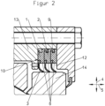
- the snap connection 9 is provided, as in Figure 2 shown.
- FIG 2 A sealing arrangement is shown in which the seal is made of Figure 1 is arranged in an installation space 12 of a housing 13.
- the seal is arranged in a rotationally fixed manner with the holding part 2 of the spiralized profile cord 1 in the installation space 12 of the housing 13 under axial prestress and, with the sealing lip 3, encloses the machine element 14 to be sealed, here in the form of an outer bearing shell of a rolling bearing, sealing under radial prestress.
Landscapes
- Engineering & Computer Science (AREA)
- General Engineering & Computer Science (AREA)
- Mechanical Engineering (AREA)
- Manufacturing & Machinery (AREA)
- Sealing With Elastic Sealing Lips (AREA)
- Gasket Seals (AREA)
- Decoration Of Textiles (AREA)
Abstract
Description
- Die Erfindung betrifft eine Dichtung und ein Verfahren zu deren Herstellung.
- Dichtungen und Verfahren zu deren Herstellung sind allgemein bekannt, zum Beispiel aus der
DE 10 2010 051 403 A1 . - Bei der vorbekannten Dichtung handelt es sich um einen in sich geschlossenen Dichtring.
- Der Dichtring umfasst mehrere in axialer Richtung benachbart zueinander angeordnete Dichtungsprofile mit jeweils zumindest einer Dichtlippe und zumindest einer hakenförmigen Verbindungskralle, die der Dichtlippe, im Querschnitt des jeweiligen Dichtungsprofils betrachtet, benachbart zugeordnet ist.
- Die Aufgabe, die dem vorbekannten Dichtring zugrunde liegt, wird darin gesehen, dass dieser einfach und kostengünstig herstellbar ist. Außerdem soll der Dichtring durch weitere Dichtungsprofile modular erweiterbar sein.
- In Abhängigkeit vom jeweiligen Anwendungsfall können mehrere Dichtungsprofile zu dem Dichtring zusammengefügt werden. Die Dichtungsprofile können zum Beispiel aus mehreren Komponenten gefertigt sein und sind dadurch gut an den jeweiligen Anwendungsfall anpassbar. Jedes Dichtungsprofil besteht aus einem elastisch nachgiebigen Werkstoff, beispielsweise aus einem Polyurethan.
- In einem ersten Verfahrensschritt wird ein bandförmiges Dichtungsprofil hergestellt und in einem zweiten Verfahrensschritt abgelängt. Das abgelängte Dichtungsprofil wird anschließend in einem dritten Verfahrensschritt ringförmig verformt, wobei die beiden freien Enden des ringförmig verformten Dichtungsprofils in einem vierten Verfahrensschritt miteinander verbunden werden.
- Die Dichtungsprofile können beispielsweise durch ein Extrusionsverfahren hergestellt werden.
- Aus der
DE 27 05 067 A1 ist eine Mehrlippendichtung bekannt, die einzelne und in sich geschlossene Dichtringe umfasst, die übereinstimmend ausgebildet und in axialer Richtung durch jeweils eine Schnappverbindung aneinander festgelegt sind. - Oftmals werden die in sich geschlossenen Dichtringe für die Erstmontage im in sich geschlossenen Zustand montiert.
- Für einen Austausch einer Dichtung können konstruktiv anspruchsvolle Dichtungsanordnungen, insbesondere solche mit großen Abmessungen, sinnvollerweise nicht zeit- und kostenaufwendig demontiert werden, nur um eine alte Dichtung durch eine neue zu ersetzen.
- Sollte ein Austausch einer Dichtung erforderlich werden, wird deshalb der vorher durch Zerschneiden aufgetrennte Dichtring aus seinem Einbauraum in der Dichtungsanordnung zunächst entfernt und ein neuer, ebenfalls aufgetrennter Dichtring zum Beispiel um eine Welle der Dichtungsanordnung in seinen Einbauraum montiert. Dieser aufgetrennte neue Dichtring muss im Anschluss an seine Montage in einem Fügeprozess deckungsgleich zusammengefügt werden, um eine Leckage während seiner Verwendung zu vermeiden. Dieser Fügeprozess kann je nach eingesetztem Material des Dichtrings durch Verstiften, Kleben, Verschweißen oder Vulkanisieren erfolgen. Dabei können als Hilfsmittel Formwerkzeuge und/ oder Stifte im Querschnitt des Dichtrings zum Einsatz kommen.
- Sowohl die Demontage eines alten als auch die Montage eines neuen Dichtrings sind dadurch unerwünscht zeit- und kostenaufwendig.
- Der Erfindung liegt die Aufgabe zu Grunde, eine Dichtung und ein Verfahren zu deren Herstellung derart weiterzuentwickeln, dass die Dichtung einfach und kostengünstig herstellbar ist. Außerdem soll die Dichtung in einem Reparaturfall einfach austauschbar sein. Insbesondere sollen eine Demontage der alten Dichtung aus ihrem Einbauraum und eine Montage einer entsprechenden neuen Dichtung in den Einbauraum einfach möglich sein, ohne die alte Dichtung bei der Demontage zerstören zu müssen und ohne dass im Anschluss an die Montage der neuen Dichtung ein Fügeprozess an der Dichtung notwendig ist.
- Diese Aufgabe wird erfindungsgemäß durch eine Dichtung mit den Merkmalen von Anspruch 1 und durch ein Verfahren mit den Merkmalen von Anspruch 9 gelöst. Auf eine vorteilhafte Ausgestaltung der Dichtung und auf eine Weiterbildung des Verfahrens nehmen die darauf jeweils rückbezogenen Ansprüche bezug.
- Zur Lösung der Aufgabe ist eine Dichtung vorgesehen, umfassend eine spiralisierte Profilschnur aus mindestens einem thermoplastischen Elastomerwerkstoff mit einem Halteteil und mit zumindest einer Dichtlippe, wobei das Halteteil und die Dichtlippe einander in radialer Richtung gegenüberliegend angeordnet sind, wobei die Profilschnur in axialer Richtung benachbart zueinander angeordnete und ineinander übergehende Wendel umfasst und stirnseitig beiderseits offene Stirnseiten aufweist. Vorzugsweise ist der thermoplastische Elastomerwerkstoff ein TPU. Hierbei ist von Vorteil, dass die Dichtung nicht als in sich geschlossener Dichtring ausgebildet ist. Die Dichtung ist vielmehr in Form einer Förderspirale ausgebildet, um während der bestimmungsgemäßen Verwendung der Dichtung abzudichtendes Medium kontinuierlich zurück in einen abzudichtenden Raum zu fördern. Abzudichtendes Medium ist beispielsweise ein Schmiermedium wie Schmierfett oder Öl.
- Dabei ist zu beachten, dass die erfindungsgemäße Dichtung drehrichtungsabhängig funktioniert, zum Beispiel abhängig von der Drehrichtung einer relativ zur Dichtung rotierenden abzudichtenden Welle.
- Dadurch, dass es sich bei der erfindungsgemäßen Dichtung nicht um einen in sich geschlossenen Dichtring handelt, ist diese besonders geeignet, um Großlager, zum Beispiel in Windkraftantrieben, abzudichten. Die abzudichtenden Durchmesser betragen in solchen Fällen üblicherweise mehr als 500 mm.
- Die in axialer Richtung aneinander angrenzenden Wendel sind im Wesentlichen übereinstimmend ausgebildet.
- Dabei weisen die Wendel in radialer Richtung einerseits das Halteteil und in radialer Richtung andererseits die Dichtlippe auf, wobei das Halteteil und die Dichtlippe entlang der axialen Richtung zwischen den offenen Stirnseiten jeweils einen im Wesentlichen konstanten Durchmesser aufweisen.
- Die Dichtung gelangt in einem Einbauraum einer Dichtungsanordnung zur Anwendung, in dem das Halteteil zum Beispiel statisch dichtend relativ drehfest in einer Gehäusebohrung festgelegt ist. Die Gehäusebohrung ist von einer abzudichtenden Welle durchdrungen. Abgedichtet wird die abzudichtende Welle durch die Dichtlippe.
- Die Wendel kann auf ihren einander axial zugewandten Seiten durch eine Schnappverbindung in radialer und in axialer Richtung formschlüssig aneinander festgelegt sein. Hierbei ist von Vorteil, dass sich die einzelnen Wendel der spiralisierten Profilschnur nicht relativ zueinander verlagern können; sie sind relativ ortsfest zueinander angeordnet. Dadurch ergeben sich gute Gebrauchseigenschaften während einer langen Gebrauchsdauer, insbesondere ein gutes Abdichtungsergebnis. Die Schnappverbindung hält nach der Montage der spiralisierten Profilschnur in einem Einbauraum einer Dichtungsanordnung die Wendel auf dem notwendigen Durchmesser formschlüssig zusammen. Die Montage der spiralisierten Profilschnur erfolgt in allen Fällen, also bei der Erstmontage und auch bei einem späteren Austausch, durch Einlegen der spiralisierten Profilschnur in den Einbauraum einer Dichtungsanordnung durch eine zunächst elastische Verformung und ein späteres Einschnappen der Schnappverbindung.
- Die spiralisierte Profilschnur ist bevorzugt unter axialer elastischer Vorspannung in ihrem Einbauraum angeordnet.
- Die Wendel können ein Wendelpaket bilden, das einen im Wesentlichen rechteckigen Querschnitt aufweist, bei dem die offenen Stirnseiten jeweils in einer gedachten Radialebene mit den jeweils axial benachbart angrenzenden Wendeln angeordnet sind. Durch eine solche Ausgestaltung ist von Vorteil, dass die Dichtung kompakte Abmessungen in axialer Richtung aufweist und ihren Einbauraum im Wesentlichen vollständig ausfüllt.
- Die axiale Umformung der spiralisierten Profilschnur zum im Wesentlichen rechteckigen Wendelpaket findet an der Stelle der spiralisierten Profilschnur statt, an der die offenen Enden der Spirale sich gegenüberstehen.
- Der Versatz der Umformung in axialer Richtung beträgt eine Profilbreite einer Wendel.
- Nach einer ersten Ausgestaltung kann es vorgesehen sein, dass die Profilschnur aus mindestens einem thermoplastischen Werkstoff besteht und dass das Halteteil und die Dichtlippe einstückig ineinander übergehend und materialeinheitlich ausgebildet sind. Hierbei ist von Vorteil, dass die Dichtung einfach und kostengünstig herstellbar ist. Außerdem ist von Vorteil, dass die Dichtung im Anschluss an ihre bestimmungsgemäße Verwendung sortenrein recyclebar ist.
- Nach einer anderen Ausgestaltung kann es vorgesehen sein, dass die Profilschnur aus zwei voneinander abweichenden Werkstoffen für Halteteil und Dichtlippe besteht. Hierbei ist von Vorteil, dass das Halteteil und die Dichtlippe durch die für den jeweiligen Anwendungsfall jeweils besonders geeigneten Werkstoffe jeweils funktionstechnisch individualisiert sind. Dadurch wird die Profilschnur mittels des Halteteils besonders zuverlässig innerhalb des Einbauraums gehalten, und die Dichtlippe dichtet ein abzudichtendes Maschinenelement besonders zuverlässig ab.
- Zumindest einer der Werkstoffe kann ein Polyurethan sein. Ein solcher Werkstoff hat den Vorteil, dass er gut thermoplastisch verarbeitbar ist. Bevorzugt wird die Profilschnur durch Extrusion hergestellt. Ein solches Verfahren ist rationell und kostengünstig durchführbar. Außerdem hat Polyurethan eine gute Verschleißfestigkeit und eine ausgezeichnete Abriebfestigkeit, eine hohe Festigkeit und eine hohe Bruchdehnung. Der Werkstoff ist innerhalb eines weiten Temperaturbereichs mineralölbeständig und weist eine ausgezeichnete Ozon- und Oxidationsbeständigkeit auf. Er hat ein gutes Dämpfungsverhalten, eine sehr gute Kälteflexibilität und eine hohe Beständigkeit gegen Rissbildung; der Werkstoff weist eine hohe Weiterreißfestigkeit auf.
- Das Verfahren zur Herstellung der Dichtung ist dadurch gekennzeichnet, dass in einem ersten Verfahrensschritt eine spiralisierte Profilschnur hergestellt wird, wobei in einem zweiten Verfahrensschritt die spiralisierte Profilschnur entsprechend einer Einbaulänge eines Einbauraums in einer Dichtungsanordnung, in der die Dichtung zur Anwendung gelangen soll, abgelängt wird. Die Profilschnur wird bevorzugt aus einem thermoplastischen Polyurethangranulat extrudiert und in einem kontinuierlichen Umformungsprozess zu einem Dichtprofil geformt. Das Dichtprofil kann die zuvor beschriebene Schnappverbindung aufweisen.
- Der Herstellungsprozess ist besonders einfach. Separate Werkzeuge wie bei der Vulkanisation oder der Rohrgießerei von Polyurethanen sind nicht notwendig.
- Lediglich erforderlich ist ein Werkzeug für eine bestimmte Geometrie der Profilschnur, die dann für alle erforderlichen unterschiedlichen Durchmesser verwendet werden kann.
- Das Verfahren erfolgt derart, dass ein Granulat über einen Extruder plastifiziert und durch ein erwärmtes Werkzeug kontinuierlich umgeformt wird.
- In einem dritten Verfahrensschritt kann die spiralisierte Profilschnur in axialer Richtung zu dem im Wesentlichen rechteckigen Wendelpaket gestaucht werden, wobei im dritten Verfahrensschritt dabei gleichzeitig mit der axialen Stauchung zum Wendelpakte die Schnappverbindung zwischen den einander benachbarten Wendeln eingeschnappt wird. Dadurch ist die gebrauchsfertige Dichtung hergestellt.
- Ein Ausführungsbeispiel der erfindungsgemäßen Dichtung wird nachfolgend anhand der
Figuren 1 und2 näher erläutert. - Diese zeigen jeweils in schematischer Darstellung:
- Figur 1
- die Dichtung als Einzelteil, wobei die spiralisierte Profilschnur das Wendelpakt bildet,
- Figur 2
- die Dichtung aus
Figur 1 , eingebaut in den Einbauraum einer Dichtungsanordnung. - In
Figur 1 ist ein Ausführungsbeispiel der erfindungsgemäßen Dichtung gezeigt. Die Dichtung ist als Förderspirale ausgebildet und umfasst die spiralisierte Profilschnur 1 mit dem Halteteil 2 und der Dichtlippe 3. Das Halteteil 2 und die Dichtlippe 3 sind einander in radialer Richtung 4 gegenüberliegend angeordnet. Die Profilschnur 1 umfasst in axialer Richtung 5 benachbart zueinander angeordnete und ineinander übergehende Wendel 6 und weist stirnseitig beiderseits die offenen Stirnseiten 7, 8 auf. - Die Wendel 6 bilden das Wendelpaket 10 mit einem im Wesentlichen rechteckigen Querschnitt. Die offenen Stirnseiten 7, 8 sind jeweils in einer gedachten Radialebene 11 mit den jeweils axial benachbart angrenzenden Wendeln 6 angeordnet.
- Um die Wendel 6 der spiralisierten Profilschnur 1 in radialer 4 und axialer Richtung 5 formschlüssig aneinander festzulegen, ist die Schnappverbindung 9 vorgesehen, wie in
Figur 2 gezeigt. - In
Figur 2 ist eine Dichtungsanordnung gezeigt, in der die Dichtung ausFigur 1 in einem Einbauraum 12 eines Gehäuses 13 angeordnet ist. Die Dichtung ist mit dem Halteteil 2 der spiralisierten Profilschnur 1 im Einbauraum 12 des Gehäuses 13 unter axialer Vorspannung drehfest angeordnet und umschließt mit der Dichtlippe 3 das abzudichtende Maschinenelement 14, hier in Form einer äußeren Lagerschale eines Wälzlagers, unter radialer Vorspannung dichtend.
Claims (11)
- Dichtung, umfassend eine spiralisierte Profilschnur (1) aus mindestens einem thermoplastischen Elastomerwerkstoff mit einem Halteteil (2) und mit zumindest einer Dichtlippe (3), die einander in radialer Richtung (4) gegenüberliegend angeordnet sind, wobei die Profilschnur (1) in axialer Richtung (5) benachbart zueinander angeordnete und ineinander übergehende Wendel (6) umfasst und stirnseitig beiderseits offene Stirnseiten (7, 8) aufweist.
- Dichtung nach Anspruch 1, dadurch gekennzeichnet, dass die Wendel (6) im Wesentlichen übereinstimmend ausgebildet sind.
- Dichtung nach einem der Ansprüche 1 oder 2, dadurch gekennzeichnet, dass die Wendel (6) in radialer Richtung (4) einerseits das Halteteil (2) und in radialer (4) Richtung andererseits die Dichtlippe (3) aufweisen und dass das Halteteil (2) und die Dichtlippe (3) entlang der axialen Richtung (5) zwischen den Stirnseiten (7, 8) jeweils einen im Wesentlichen konstanten Durchmesser aufweisen.
- Dichtung nach einem der Ansprüche 1 bis 3, dadurch gekennzeichnet, dass die Wendel (6) auf ihren einander axial zugewandten Seiten durch eine Schnappverbindung (9) in radialer (4) und axialer Richtung (5) formschlüssig aneinander festgelegt sind.
- Dichtung nach einem der Ansprüche 1 bis 4, dadurch gekennzeichnet, dass die Wendel (6) ein Wendelpaket (10) bilden, das einen im Wesentlichen rechteckigen Querschnitt aufweist, bei dem die offenen Stirnseiten (7, 8) jeweils in einer gedachten Radialebene (11) mit den jeweils axial benachbart angrenzenden Wendeln (6) angeordnet sind.
- Dichtung nach einem der Ansprüche 1 bis 5, dadurch gekennzeichnet, dass die Profilschnur (1) aus einem thermoplastischen Werkstoff besteht und dass das Halteteil (2) und die Dichtlippe (3) einstückig ineinander übergehend und materialeinheitlich ausgebildet sind.
- Dichtung nach einem der Ansprüche 1 bis 5, dadurch gekennzeichnet, dass die Profilschnur (1) aus zwei voneinander abweichenden Werkstoffen für Halteteil (2) und Dichtlippe (3) besteht.
- Dichtung nach einem der Ansprüche 6 oder 7, dadurch gekennzeichnet, dass zumindest einer der Werkstoffe ein Polyurethan ist.
- Verfahren zur Herstellung einer Dichtung nach einem der Ansprüche 1 bis 8, dadurch gekennzeichnet, dass in einem ersten Verfahrensschritt eine spiralisierte Profilschnur (1) hergestellt wird, wobei in einem zweiten Verfahrensschritt die spiralisierte Profilschnur (1) entsprechend einer Einbaulänge eines Einbauraums in einer Dichtungsanordnung, in der die Dichtung zur Anwendung gelangen soll, abgelängt wird.
- Verfahren nach Anspruch 9, dadurch gekennzeichnet, dass in einem dritten Verfahrensschritt die spiralisierte Profilschnur (1) in axialer Richtung (5) zum im Wesentlichen rechteckigen Wendelpaket (10) gestaucht wird.
- Verfahren nach Anspruch 10, dadurch gekennzeichnet, dass im dritten Verfahrensschritt, gleichzeitig mit der axialen Stauchung zum Wendelpaket (10), die Schnappverbindung (9) zwischen den Wendeln (6) eingeschnappt wird.
Applications Claiming Priority (1)
| Application Number | Priority Date | Filing Date | Title |
|---|---|---|---|
| DE102022105295.8A DE102022105295B3 (de) | 2022-03-07 | 2022-03-07 | Dichtung und Verfahren zu deren Herstellung |
Publications (3)
| Publication Number | Publication Date |
|---|---|
| EP4242497A1 true EP4242497A1 (de) | 2023-09-13 |
| EP4242497C0 EP4242497C0 (de) | 2024-12-18 |
| EP4242497B1 EP4242497B1 (de) | 2024-12-18 |
Family
ID=85381305
Family Applications (1)
| Application Number | Title | Priority Date | Filing Date |
|---|---|---|---|
| EP23158091.1A Active EP4242497B1 (de) | 2022-03-07 | 2023-02-23 | Dichtung und verfahren zu deren herstellung |
Country Status (7)
| Country | Link |
|---|---|
| US (2) | US20230279948A1 (de) |
| EP (1) | EP4242497B1 (de) |
| CN (1) | CN116717598A (de) |
| AU (1) | AU2023200808B2 (de) |
| CA (1) | CA3192094A1 (de) |
| DE (1) | DE102022105295B3 (de) |
| ES (1) | ES3014047T3 (de) |
Citations (5)
| Publication number | Priority date | Publication date | Assignee | Title |
|---|---|---|---|---|
| DE2705067A1 (de) | 1976-02-23 | 1977-08-25 | Garlock Inc | Dichtelement nach art einer lippendichtung, vorzugsweise fuer eine mehrlippendichtung |
| US6045136A (en) * | 1997-06-16 | 2000-04-04 | Garlock Inc. | Split sealing element |
| EP1701070A1 (de) * | 2005-03-08 | 2006-09-13 | Carl Freudenberg KG | Dichtungsvorrichtung |
| DE102010051403A1 (de) | 2010-11-16 | 2012-05-16 | Carl Freudenberg Kg | Dichtung und Verfahren zur Herstellung eines Dichtrings |
| US20190120385A1 (en) * | 2017-10-19 | 2019-04-25 | System Seals, Inc. | Shaft seal with helical sealing lip |
Family Cites Families (6)
| Publication number | Priority date | Publication date | Assignee | Title |
|---|---|---|---|---|
| DE19904416A1 (de) * | 1999-02-04 | 2000-08-24 | Mtu Friedrichshafen Gmbh | Wellendichtring |
| JP3944361B2 (ja) * | 2001-05-17 | 2007-07-11 | 日本ピラー工業株式会社 | グランドパッキンの構成材 |
| US7419165B2 (en) * | 2004-08-18 | 2008-09-02 | Federal-Mogul World Wide, Inc. | Seal assembly and method of manufacturing the same |
| CN203283374U (zh) * | 2012-05-04 | 2013-11-13 | 昱曦机械高新科技有限公司 | 用于在艉管中密封螺旋桨轴的螺旋桨轴密封装置 |
| DE102013218904B4 (de) | 2013-09-20 | 2015-09-17 | Aktiebolaget Skf | Dichtungselement |
| JP2017075638A (ja) * | 2015-10-14 | 2017-04-20 | 大豊工業株式会社 | シール構造およびシール部材 |
-
2022
- 2022-03-07 DE DE102022105295.8A patent/DE102022105295B3/de active Active
-
2023
- 2023-02-14 AU AU2023200808A patent/AU2023200808B2/en active Active
- 2023-02-23 ES ES23158091T patent/ES3014047T3/es active Active
- 2023-02-23 EP EP23158091.1A patent/EP4242497B1/de active Active
- 2023-03-02 CN CN202310192556.4A patent/CN116717598A/zh active Pending
- 2023-03-03 US US18/177,786 patent/US20230279948A1/en active Pending
- 2023-03-06 CA CA3192094A patent/CA3192094A1/en active Pending
-
2024
- 2024-05-28 US US18/675,306 patent/US20240309950A1/en active Pending
Patent Citations (5)
| Publication number | Priority date | Publication date | Assignee | Title |
|---|---|---|---|---|
| DE2705067A1 (de) | 1976-02-23 | 1977-08-25 | Garlock Inc | Dichtelement nach art einer lippendichtung, vorzugsweise fuer eine mehrlippendichtung |
| US6045136A (en) * | 1997-06-16 | 2000-04-04 | Garlock Inc. | Split sealing element |
| EP1701070A1 (de) * | 2005-03-08 | 2006-09-13 | Carl Freudenberg KG | Dichtungsvorrichtung |
| DE102010051403A1 (de) | 2010-11-16 | 2012-05-16 | Carl Freudenberg Kg | Dichtung und Verfahren zur Herstellung eines Dichtrings |
| US20190120385A1 (en) * | 2017-10-19 | 2019-04-25 | System Seals, Inc. | Shaft seal with helical sealing lip |
Also Published As
| Publication number | Publication date |
|---|---|
| AU2023200808A1 (en) | 2023-09-21 |
| US20240309950A1 (en) | 2024-09-19 |
| CN116717598A (zh) | 2023-09-08 |
| AU2023200808B2 (en) | 2024-05-23 |
| CA3192094A1 (en) | 2023-09-07 |
| EP4242497C0 (de) | 2024-12-18 |
| US20230279948A1 (en) | 2023-09-07 |
| ES3014047T3 (en) | 2025-04-16 |
| EP4242497B1 (de) | 2024-12-18 |
| DE102022105295B3 (de) | 2023-06-15 |
Similar Documents
| Publication | Publication Date | Title |
|---|---|---|
| DE102009014923C5 (de) | Zweireihiges Kegelrollenlager, insbesondere zur Lagerung einer Rotorwelle einer Windkraftanlage | |
| DE69937495T2 (de) | Wellendichtung und verfahren zur herstellung | |
| EP2238315B1 (de) | Vorrichtung mit Dichtsegment | |
| DE10209933B4 (de) | Gegenbahngelenk | |
| EP1270987A2 (de) | Aggregatelager in Buchsenform | |
| DE102010051403A1 (de) | Dichtung und Verfahren zur Herstellung eines Dichtrings | |
| DE69527230T2 (de) | Lager | |
| DE2756403A1 (de) | Dichtung | |
| DE102006021011B4 (de) | Buchsenlager mit axialseitig profiliertem Lagerkörper | |
| EP1731804A1 (de) | Dichtung und Anordnung mit in Reihe geschalteten Dichtlippen | |
| DE112019004733T5 (de) | Kugellagerhalterung und Wälzlager | |
| EP1612066A1 (de) | Ringscheibe für ein Gleitlager | |
| DE102004031559B4 (de) | Elastomeres Buchsenlager mit verbessertem Torsionsverhalten | |
| DE2453645C3 (de) | Elastische Verbindungsvorrichtung für zwei im wesentlichen koaxiale Teile | |
| EP4242497B1 (de) | Dichtung und verfahren zu deren herstellung | |
| EP1077780B1 (de) | Gebaute aufweitlanze | |
| EP3862599A1 (de) | Lamellendichtring mit x-förmiger querschnittsgeometrie | |
| DE10234305A1 (de) | Dichtring zur Abdichtung eines Längenausgleichs einer Gelenkwelle | |
| DE102019208243A1 (de) | Spannungswellengetriebe | |
| DE10240282B4 (de) | Radialwälzlager | |
| DE102017215218A1 (de) | Kreuzgelenk mit einer Dichtung, Dichtung sowie Verfahren zur Montage einer Dichtung | |
| EP1783384B1 (de) | Kreuzgelenkanordnung | |
| DE102020003214A1 (de) | Ventilschaftdichtung für eine Verbrennungskraftmaschine eines Kraftfahrzeugs | |
| DE102022206783B4 (de) | Einführelement zum Einführen und Positionieren eines Wellenelementes, System mit dem Einführelement, ein Verfahren zum Zusammenbau des Systems sowie ein Verfahren zum Austausch eines Bauteils in dem System | |
| EP3786496B1 (de) | Radialwellendichtung |
Legal Events
| Date | Code | Title | Description |
|---|---|---|---|
| PUAI | Public reference made under article 153(3) epc to a published international application that has entered the european phase |
Free format text: ORIGINAL CODE: 0009012 |
|
| STAA | Information on the status of an ep patent application or granted ep patent |
Free format text: STATUS: THE APPLICATION HAS BEEN PUBLISHED |
|
| AK | Designated contracting states |
Kind code of ref document: A1 Designated state(s): AL AT BE BG CH CY CZ DE DK EE ES FI FR GB GR HR HU IE IS IT LI LT LU LV MC ME MK MT NL NO PL PT RO RS SE SI SK SM TR |
|
| STAA | Information on the status of an ep patent application or granted ep patent |
Free format text: STATUS: REQUEST FOR EXAMINATION WAS MADE |
|
| 17P | Request for examination filed |
Effective date: 20230920 |
|
| RBV | Designated contracting states (corrected) |
Designated state(s): AL AT BE BG CH CY CZ DE DK EE ES FI FR GB GR HR HU IE IS IT LI LT LU LV MC ME MK MT NL NO PL PT RO RS SE SI SK SM TR |
|
| GRAP | Despatch of communication of intention to grant a patent |
Free format text: ORIGINAL CODE: EPIDOSNIGR1 |
|
| STAA | Information on the status of an ep patent application or granted ep patent |
Free format text: STATUS: GRANT OF PATENT IS INTENDED |
|
| INTG | Intention to grant announced |
Effective date: 20240711 |
|
| GRAS | Grant fee paid |
Free format text: ORIGINAL CODE: EPIDOSNIGR3 |
|
| GRAA | (expected) grant |
Free format text: ORIGINAL CODE: 0009210 |
|
| STAA | Information on the status of an ep patent application or granted ep patent |
Free format text: STATUS: THE PATENT HAS BEEN GRANTED |
|
| RIN1 | Information on inventor provided before grant (corrected) |
Inventor name: FIETZ, ROLAND Inventor name: STRUEBING, FRANK Inventor name: KUHNERT, JENS Inventor name: FINK, ANDREJ Inventor name: ILINSEER, ALBERT Inventor name: BARILLAS, GONZALO |
|
| AK | Designated contracting states |
Kind code of ref document: B1 Designated state(s): AL AT BE BG CH CY CZ DE DK EE ES FI FR GB GR HR HU IE IS IT LI LT LU LV MC ME MK MT NL NO PL PT RO RS SE SI SK SM TR |
|
| REG | Reference to a national code |
Ref country code: CH Ref legal event code: EP |
|
| REG | Reference to a national code |
Ref country code: DE Ref legal event code: R096 Ref document number: 502023000392 Country of ref document: DE |
|
| REG | Reference to a national code |
Ref country code: IE Ref legal event code: FG4D Free format text: LANGUAGE OF EP DOCUMENT: GERMAN |
|
| U01 | Request for unitary effect filed |
Effective date: 20241219 |
|
| U07 | Unitary effect registered |
Designated state(s): AT BE BG DE DK EE FI FR IT LT LU LV MT NL PT RO SE SI Effective date: 20250110 |
|
| U20 | Renewal fee for the european patent with unitary effect paid |
Year of fee payment: 3 Effective date: 20250224 |
|
| PG25 | Lapsed in a contracting state [announced via postgrant information from national office to epo] |
Ref country code: HR Free format text: LAPSE BECAUSE OF FAILURE TO SUBMIT A TRANSLATION OF THE DESCRIPTION OR TO PAY THE FEE WITHIN THE PRESCRIBED TIME-LIMIT Effective date: 20241218 |
|
| REG | Reference to a national code |
Ref country code: ES Ref legal event code: FG2A Ref document number: 3014047 Country of ref document: ES Kind code of ref document: T3 Effective date: 20250416 |
|
| PG25 | Lapsed in a contracting state [announced via postgrant information from national office to epo] |
Ref country code: NO Free format text: LAPSE BECAUSE OF FAILURE TO SUBMIT A TRANSLATION OF THE DESCRIPTION OR TO PAY THE FEE WITHIN THE PRESCRIBED TIME-LIMIT Effective date: 20250318 |
|
| PG25 | Lapsed in a contracting state [announced via postgrant information from national office to epo] |
Ref country code: GR Free format text: LAPSE BECAUSE OF FAILURE TO SUBMIT A TRANSLATION OF THE DESCRIPTION OR TO PAY THE FEE WITHIN THE PRESCRIBED TIME-LIMIT Effective date: 20250319 |
|
| PG25 | Lapsed in a contracting state [announced via postgrant information from national office to epo] |
Ref country code: RS Free format text: LAPSE BECAUSE OF FAILURE TO SUBMIT A TRANSLATION OF THE DESCRIPTION OR TO PAY THE FEE WITHIN THE PRESCRIBED TIME-LIMIT Effective date: 20250318 |
|
| PG25 | Lapsed in a contracting state [announced via postgrant information from national office to epo] |
Ref country code: SM Free format text: LAPSE BECAUSE OF FAILURE TO SUBMIT A TRANSLATION OF THE DESCRIPTION OR TO PAY THE FEE WITHIN THE PRESCRIBED TIME-LIMIT Effective date: 20241218 |
|
| PG25 | Lapsed in a contracting state [announced via postgrant information from national office to epo] |
Ref country code: PL Free format text: LAPSE BECAUSE OF FAILURE TO SUBMIT A TRANSLATION OF THE DESCRIPTION OR TO PAY THE FEE WITHIN THE PRESCRIBED TIME-LIMIT Effective date: 20241218 |
|
| PG25 | Lapsed in a contracting state [announced via postgrant information from national office to epo] |
Ref country code: IS Free format text: LAPSE BECAUSE OF FAILURE TO SUBMIT A TRANSLATION OF THE DESCRIPTION OR TO PAY THE FEE WITHIN THE PRESCRIBED TIME-LIMIT Effective date: 20250418 |
|
| PG25 | Lapsed in a contracting state [announced via postgrant information from national office to epo] |
Ref country code: SK Free format text: LAPSE BECAUSE OF FAILURE TO SUBMIT A TRANSLATION OF THE DESCRIPTION OR TO PAY THE FEE WITHIN THE PRESCRIBED TIME-LIMIT Effective date: 20241218 |
|
| PG25 | Lapsed in a contracting state [announced via postgrant information from national office to epo] |
Ref country code: CZ Free format text: LAPSE BECAUSE OF FAILURE TO SUBMIT A TRANSLATION OF THE DESCRIPTION OR TO PAY THE FEE WITHIN THE PRESCRIBED TIME-LIMIT Effective date: 20241218 |
|
| PG25 | Lapsed in a contracting state [announced via postgrant information from national office to epo] |
Ref country code: MC Free format text: LAPSE BECAUSE OF FAILURE TO SUBMIT A TRANSLATION OF THE DESCRIPTION OR TO PAY THE FEE WITHIN THE PRESCRIBED TIME-LIMIT Effective date: 20241218 |
|
| PLBE | No opposition filed within time limit |
Free format text: ORIGINAL CODE: 0009261 |
|
| STAA | Information on the status of an ep patent application or granted ep patent |
Free format text: STATUS: NO OPPOSITION FILED WITHIN TIME LIMIT |
|
| 26N | No opposition filed |
Effective date: 20250919 |
|
| PG25 | Lapsed in a contracting state [announced via postgrant information from national office to epo] |
Ref country code: IE Free format text: LAPSE BECAUSE OF NON-PAYMENT OF DUE FEES Effective date: 20250223 |
|
| U20 | Renewal fee for the european patent with unitary effect paid |
Year of fee payment: 4 Effective date: 20260224 |
|
| PGFP | Annual fee paid to national office [announced via postgrant information from national office to epo] |
Ref country code: ES Payment date: 20260317 Year of fee payment: 4 |
|
| PGFP | Annual fee paid to national office [announced via postgrant information from national office to epo] |
Ref country code: TR Payment date: 20260204 Year of fee payment: 4 |