EP4242067A1 - Kamerahalterung zur befestigung an einem fahrzeugaufbau - Google Patents
Kamerahalterung zur befestigung an einem fahrzeugaufbau Download PDFInfo
- Publication number
- EP4242067A1 EP4242067A1 EP23158180.2A EP23158180A EP4242067A1 EP 4242067 A1 EP4242067 A1 EP 4242067A1 EP 23158180 A EP23158180 A EP 23158180A EP 4242067 A1 EP4242067 A1 EP 4242067A1
- Authority
- EP
- European Patent Office
- Prior art keywords
- camera
- casing
- wall
- carrier part
- housing
- Prior art date
- Legal status (The legal status is an assumption and is not a legal conclusion. Google has not performed a legal analysis and makes no representation as to the accuracy of the status listed.)
- Granted
Links
Images





Classifications
-
- B—PERFORMING OPERATIONS; TRANSPORTING
- B60—VEHICLES IN GENERAL
- B60R—VEHICLES, VEHICLE FITTINGS, OR VEHICLE PARTS, NOT OTHERWISE PROVIDED FOR
- B60R11/00—Arrangements for holding or mounting articles, not otherwise provided for
- B60R11/04—Mounting of cameras operative during drive; Arrangement of controls thereof relative to the vehicle
-
- B—PERFORMING OPERATIONS; TRANSPORTING
- B60—VEHICLES IN GENERAL
- B60R—VEHICLES, VEHICLE FITTINGS, OR VEHICLE PARTS, NOT OTHERWISE PROVIDED FOR
- B60R2300/00—Details of viewing arrangements using cameras and displays, specially adapted for use in a vehicle
- B60R2300/10—Details of viewing arrangements using cameras and displays, specially adapted for use in a vehicle characterised by the type of camera system used
- B60R2300/105—Details of viewing arrangements using cameras and displays, specially adapted for use in a vehicle characterised by the type of camera system used using multiple cameras
Definitions
- the present invention relates to a camera holder for attachment to a vehicle body of a motor vehicle according to the preamble of claim 1.
- the invention further relates to a motor vehicle, in particular a bus or a commercial vehicle, and a trailer, in particular a commercial vehicle trailer.
- Camera mounts for attaching to a vehicle body are, for example, from the WO 2004/058542 A1 or the WO 2015/088396 A1 known.
- the video cameras attached to the camera holders provide, in particular, image signals to drivers of commercial vehicles, from which the driver can obtain information about areas that are not immediately visible to the side, behind or directly in front of the commercial vehicle, for example in turning situations in which people or objects are located in an area that is not immediately visible to be able to detect it at an early stage and thus avoid a collision.
- the camera mounts known from the prior art are relatively complex to manufacture or assemble due to their individual components being movable relative to one another. Particularly in the case of camera mounts that can be fixed in position in a variable manner, a calibration of the camera and its position is necessary, which cannot be easily carried out in every workshop.
- Simple retaining plates to which the cameras can be screwed are also known. However, these are not suitable for protecting the camera from external weather influences or damage from branches or the like.
- the object of the present invention is to provide a camera holder for attachment to a vehicle body of a vehicle, in particular a bus or a commercial vehicle, or to a trailer of such a vehicle, which, on the one hand, can be mounted easily and which also protects against damage.
- the camera holder according to the invention has a camera carrier part that can be fixed to the vehicle body and has at least one receiving slot for receiving at least one camera body of a camera.
- a casing can be slipped onto this camera support part.
- the casing has a receiving opening for receiving the camera carrier part and at least one window opening provided in a housing wall area, in or behind which a lens of the camera can be positioned.
- the camera carrier part and the casing each have guide contours for positioning the casing on the camera carrier part, the camera carrier part and the casing being releasably attachable to one another.
- the camera can be easily inserted into the camera carrier part in a predetermined position.
- the casing can be slipped onto the camera carrier part in a simple manner.
- the inversion movement is guided by the guide contours.
- the releasable fastenability of the casing on the camera carrier part enables a simple pre-positioning of the casing on the camera carrier part, especially in a case in which the casing is to be additionally glued to the vehicle body after it has been slipped onto the camera carrier part attached to the vehicle body.
- the adhesive joint also takes on a sealing function.
- the receiving shaft limited by an outer wall and an inner wall of the camera support part aligned parallel thereto, the outer wall and the inner wall each having a blind hole-like recess with sliding edges aligned parallel to one another.
- the lens can be accommodated in the recess in the outer wall and a plug-in connection of the camera protruding from the back of the camera body can be accommodated in the recess in the inner wall.
- the camera body can be accommodated between the outer wall and the inner wall.
- the receiving shaft designed in this way and the recesses in the outer wall and the inner wall make it possible to easily pre-fix the camera.
- the recesses are already shaped in such a way that the camera can be positioned in a position intended for it in the camera carrier part without further position calibration and is fixed in place after the cover housing has been pushed on.
- the receiving shaft has a guide wall, the guide wall having a blind hole-like recess with sliding edges aligned parallel to one another, the sliding edges protruding into lateral grooves of the camera body.
- This design variant also makes it possible to easily pre-fix the camera.
- the camera carrier part has two receiving shafts arranged at an angle to one another for accommodating a camera each, and the casing has two window openings in housing wall areas aligned at an angle to one another for accommodating a lens of a respective camera.
- a camera holder designed in this way enables the recording of two cameras positioned at an angle to one another in a simple manner.
- the two cameras are arranged at an appropriate angle and the camera lenses are preferably designed as so-called fish-eye lenses, this is virtually the case All-round observation around the location where the cameras are fixed on the vehicle body is possible.
- the camera carrier part with more than two receiving shafts for each camera and a corresponding design of the casing with a number of window openings corresponding to the number of receiving shafts.
- the camera carrier part and the casing are secured to one another by several releasable snap connections.
- the camera carrier part has locking tongues which extend from a rear mounting wall in the direction of a front end and have locking lugs formed thereon, which are locked into respective locking receptacles in the inside of a housing wall of the housing when the housing is in the pushed-on state.
- the locking lugs are provided with chamfers for releasing the locking from a predetermined force on the casing against a pushing-on direction.
- the casing can be easily removed from the camera support part if necessary without having to destroy the casing.
- a pin-like guide contour is formed from the inside of the housing wall of the casing in the area of the front end, which, when pushed onto the camera carrier part, projects into a guide contour designed as a recess in a front wall of the camera carrier part.
- the guide contours of the casing and the camera carrier part thus enable an exact positioning of the casing housing on the camera carrier part in a simple manner, in order in particular to precisely align the windows of the casing housing relative to the camera carrier part and thus prevent the lens of the respective camera from being partially obscured.
- the inside is more lateral Areas of the housing wall of the enveloping housing are formed with at least one guide contour designed as a projection or groove, which, when pushed onto the camera carrier part, projects into a guide contour designed as a recess or projection in the mounting wall of the camera carrier part.
- a bottom of the housing wall of the casing has a drain opening through which the water that has entered can drain out of the casing.
- the drain opening is shielded in the direction of the cameras by panels which are arranged, in particular formed, on an outside facing away from the interior of the enveloping housing and/or an inside facing the interior of the enveloping housing.
- the receiving opening of the enveloping housing is framed by a sealing lip for contact with the vehicle body.
- the end face of the sealing lip facing away from the front end of the casing has a groove for receiving an adhesive.
- this enables the groove to be filled with a preferably liquid or viscous adhesive before the casing is slipped onto the camera support part.
- the casing is then bonded to the vehicle body and thus the camera holder is additionally fixed to the vehicle body.
- Gluing the casing to the vehicle body also reduces the load on the snap connections between the camera carrier part and the casing, since once the adhesive has dried out it takes over the majority of the fastening load.
- the at least one window opening provided in the housing wall area is closed by a transparent material.
- the vehicle according to the invention in particular a bus or commercial vehicle, is characterized by a camera holder as described above.
- the trailer according to the invention in particular a commercial vehicle trailer, is characterized by a camera holder as described above.
- top, bottom, left, right, front, back, etc. refer exclusively to the exemplary representation and position of the camera holder, camera carrier part, housing, recording shaft, window opening and the like selected in the respective figures. These terms are not to be understood as restrictive, i.e. these relationships can change due to different working positions or the mirror-symmetrical design or the like.
- the reference number 1 denotes a total embodiment variant of a camera holder according to the invention.
- the camera holder 1 can be attached to a vehicle body of a motor vehicle, preferably a bus or commercial vehicle, or to a trailer of such a motor vehicle or commercial vehicle, in order to visually, depending on the location on the vehicle body, surrounding areas to the side, behind or in front of the vehicle body for the vehicle driver via the signal of a or to make several cameras attached to the camera holder 1, in particular video cameras, visible.
- a motor vehicle preferably a bus or commercial vehicle
- a trailer of such a motor vehicle or commercial vehicle in order to visually, depending on the location on the vehicle body, surrounding areas to the side, behind or in front of the vehicle body for the vehicle driver via the signal of a or to make several cameras attached to the camera holder 1, in particular video cameras, visible.
- the camera holder 1 essentially consists of a camera support part 3 that can be fixed to the vehicle body, as also shown in the Figures 3 - 6 is shown, and a casing 2 that can be pushed onto the camera carrier part 3, which is after the camera carrier part 3 has been fixed to the vehicle body and the insertion of a or in the Figures 3 and 4 In the exemplary embodiment shown, two cameras are placed on the camera carrier part 3.
- the camera carrier part 3 has at least one receiving shaft 32 for receiving at least one camera body 41 of a camera 4.
- the camera carrier part 3 has two such recording shafts 32, with a camera 4 being able to be placed in each of the recording shafts 32.
- the casing 2 has a receiving opening 20 on the rear side that touches the vehicle body in the assembled state, which serves to accommodate the camera carrier part 3.
- the enveloping housing 2 has at least one window opening 25 provided in a housing wall area 24, shown in Figure 7 , in or behind which a lens 42 of the camera 4 can be positioned.
- the front end of the lens 42 of the camera 4 protrudes into the window opening 25.
- the window opening 25 is accordingly designed to be open.
- the camera carrier part 3 has a mounting wall 31, which is attached to the vehicle body, for example by rivets or screws, which can be carried out through holes 311 provided for this purpose in the mounting wall 31.
- each of the receiving shafts 32 of the camera carrier part 3 is delimited by an outer wall 33 and an inner wall 34 of the camera carrier part 3 aligned parallel thereto.
- the outer wall 33 has a blind hole-like recess 331 with sliding edges 332 aligned parallel to one another. Furthermore, the inner wall 34 each has a blind hole-like recess 341 with sliding edges 342 aligned parallel to one another.
- This embodiment enables a respective camera 4 to be easily inserted, with the sliding edges 332 of the outer wall 33 being spaced so far apart that the lens 42 of the camera 4 can be inserted between them with its lateral surface sliding along them.
- the sliding edges 342 of the respective inner wall 34 serve to accommodate the plug-in connection 43 of the camera 4, whereby here too the distance between the sliding edges 342 running parallel to one another corresponds to the diameter of the plug-in connection 43 of the camera 4, so that a lateral surface of the plug-in connection 43 slides along the sliding edges 342 can be inserted.
- a respective part-circular support serves to support the lens 42 or the plug-in connection 43 of the camera 4, so that the camera 4 is fixed in a stationary manner in a horizontal plane.
- the distance between the inner wall 34 and the outer wall 33 preferably corresponds to the depth of the camera body 41 of the camera 4.
- the depth of the camera body 41 is considered to be a direction parallel to the longitudinal direction of the lens 41 of the respective camera 4.
- the camera body 41 is designed with laterally introduced grooves 44, which serve to accommodate the mutually parallel sliding edges 332 of a blind hole-like recess 331 in the outer wall 33 of a camera support part 3 '.
- An inner wall 34 with a blind hole-like recess 341 is not necessary in this embodiment variant, since the holder of the camera body 41 in the outer wall 33 of the camera support part 3 'already already predetermines one Alignment and stationary fixation of the camera 4 in the horizontal plane is guaranteed.
- outer wall 33 or the outer walls 33 with a groove for receiving guide webs protruding laterally from the camera housing for fixing the camera (s) 4 in the horizontal plane on a camera support part 3 'with outer walls 33 as described above.
- the camera carrier part 3 and the casing housing 2 each have guide contours 26, 29A, 29B, 351, 37A, 37B for positioning the casing housing 2 on the camera carrier part 3.
- the camera carrier part 3 and the casing 2 can be detachably attached to one another, preferably locked.
- the casing 2 can also be mounted on the camera support part 3 using other fastening elements, preferably screws. In this case there is no need for a lock.
- the releasable lockability is achieved in the embodiment variant shown here in that the camera carrier part 3 and the casing 2 are secured to one another by several releasable snap connections.
- the camera carrier part 3 has locking tongues 36 with locking lugs 361 formed thereon, extending from a rear mounting wall 31 towards a front end.
- the locking lugs 361 are in the pushed-on state of the casing 2 in respective locking receptacles 27, for example shown in Figure 7 , snapped into the inside of the housing wall 21 of the casing 2.
- the locking lugs 361 are preferably provided with chamfers 362 for releasing the locking from a predetermined force on the casing 2 against a sliding direction A.
- a pin-like guide contour 26 is formed from the inside of the housing wall 21 of the casing 2 in the area of the front end, which, when pushed onto the camera carrier part 3, protrudes into a guide contour 351 designed as a recess in a front wall 35 of the camera carrier part 3.
- At least one guide contour 29A, 29B designed as a projection or groove is formed from the inside of lateral regions of the housing wall 21 of the casing housing 2, which, when the casing housing 2 is pushed onto the camera carrier part 3, turns into a guide contour 37A, 37B designed as a recess or projection protrudes in the mounting wall 31 of the camera support part 3.
- the guide contours 29A designed as projections, are designed as projections extending in the pushing-on direction A, on which a respective recess, here on the mounting wall 31 of the camera carrier part 3, is supported in the pushed-on state.
- the guide contour 29B shown in Figure 8 , is designed here as a groove which receives a projection 37B formed on the mounting wall 31.
- the casing 2 is designed as a closed casing except for the receiving opening 20 and the window openings 25. However, when it rains or when washing the motor vehicle, water can enter the casing 2 through the window openings 25.
- the recording opening 20 is closed by the wall of the vehicle body.
- a bottom 23 of the housing wall 21 of the casing 2 is provided with a drain opening 28.
- the drain opening 28 is designed as a hole or bore in the bottom 23 of the housing wall 21.
- a cover 281, 282 which partially shields the drain opening 28 is arranged to shield the camera 4 or cameras 4 on an outside facing away from the interior of the enveloping housing 2 and on an inside facing the interior of the enveloping housing 2.
- a cover 281, 282 which partially shields the drain opening 28 is arranged to shield the camera 4 or cameras 4 on an outside facing away from the interior of the enveloping housing 2 and on an inside facing the interior of the enveloping housing 2.
- the panels 281, 282 are formed on the casing 2.
- the panel 281 in the interior of the casing 2 is there, as in Figure 10 can be clearly seen, closed towards the cameras 4 and open towards the recording opening 20.
- the cameras 4 themselves are waterproof in this embodiment variant, which enables particularly simple and error-free installation of the camera holder 1 on the vehicle body.
- the releasable snap connections between the camera carrier part 3 and the casing housing 2 essentially serve to pre-fix the casing housing 2 on the camera carrier part 3.
- the casing 2 is preferably glued to the vehicle body after being attached to the camera carrier part 3.
- the receiving opening 20 of the enveloping housing 2 is preferably framed by a sealing lip 22 for contact with the vehicle body.
- the end face of the sealing lip 22 facing away from the front end of the casing 2 preferably has a groove 221 which serves to accommodate an adhesive.
- the casing housing 2 After the casing housing 2 has been completely pushed onto the camera carrier part 3, the casing housing 2 can be glued to the vehicle body with adhesive introduced into the groove 221 of the sealing lip 22, so that after the adhesive has dried out, the casing housing 2 can be fixed essentially by gluing it to the vehicle body he follows.
- the snap connections serve to support the adhesive connection.
Landscapes
- Engineering & Computer Science (AREA)
- Mechanical Engineering (AREA)
- Fittings On The Vehicle Exterior For Carrying Loads, And Devices For Holding Or Mounting Articles (AREA)
Abstract
Description
- Die vorliegende Erfindung betrifft eine Kamerahalterung zur Befestigung an einem Fahrzeugaufbau eines Kraftfahrzeugs gemäß dem Oberbegriff des Anspruchs 1. Die Erfindung betrifft des Weiteren ein Kraftfahrzeug, insbesondere einen Bus oder ein Nutzfahrzeug sowie einen Anhänger, insbesondere einen Nutzfahrzeuganhänger.
- Kamerahalterungen zur Befestigung an einem Fahrzeugaufbau sind beispielsweise aus der
WO 2004/058542 A1 oder derWO 2015/088396 A1 bekannt. - Solche Kamerahalterungen mit darin aufgenommenen Kameras, insbesondere Videokameras, dienen der Verbesserung der Fahrsicherheit. Die in den Kamerahalterungen befestigten Videokameras liefern insbesondere Fahrzeugführern von Nutzfahrzeugen Bildsignale, denen der Fahrzeugführer Informationen über nicht unmittelbar einsehbare Bereiche seitlich, hinter oder auch direkt vor dem Nutzfahrzeug entnehmen kann, um beispielsweise in Abbiegesituationen in einem nicht unmittelbar einsehbaren Bereich sich befindende Personen oder auch Gegenstände frühzeitig erkennen zu können und so eine Kollision zu vermeiden.
- Die aus dem Stand der Technik bekannten Kamerahalterungen sind durch ihre relativ zueinander bewegbaren einzelnen Bauteile relativ aufwändig zu fertigen bzw. zu montieren. Insbesondere bei variierbar in ihrer Position fixierbaren Kamerahalterungen ist eine Kalibrierung der Kamera und deren Position notwendig, die nicht in jeder Werkstatt ohne weiteres durchführbar ist.
- Bekannt sind auch einfache Haltebleche, an denen die Kameras verschraubt werden können. Allerdings sind diese nicht geeignet, die Kamera vor äußeren Witterungseinflüssen oder auch Beschädigung durch Äste oder dergleichen zu schützen.
- Aufgabe der vorliegenden Erfindung ist es, eine Kamerahalterung zur Befestigung an einem Fahrzeugaufbau eines Fahrzeugs, insbesondere eines Busses oder eines Nutzfahrzeugs oder an einem Anhänger eines solchen Fahrzeugs bereitzustellen, die zum einen in einfacher Weise montiert werden kann und die außerdem vor Beschädigungen schützt.
- Diese Aufgabe wird durch eine Kamerahalterung mit den Merkmalen des Anspruchs 1 gelöst.
- Die erfindungsgemäße Kamerahalterung weist ein an dem Fahrzeugaufbau fixierbares Kameraträgerteil mit wenigstens einem Aufnahmeschacht zur Aufnahme zumindest eines Kamerakorpus einer Kamera auf.
- Auf dieses Kameraträgerteil ist ein Hüllgehäuse aufstülpbar.
- Das Hüllgehäuse weist eine Aufnahmeöffnung zur Aufnahme des Kameraträgerteils und wenigstens eine in einem Gehäusewandbereich vorgesehene Fensteröffnung auf, in oder hinter der ein Objektiv der Kamera positionierbar ist.
- Das Kameraträgerteil und das Hüllgehäuse weisen jeweils Führungskonturen zur Positionierung des Hüllgehäuses auf dem Kameraträgerteil auf, wobei das Kameraträgerteil und das Hüllgehäuse lösbar aneinander befestigbar sind.
- Mit einer solchermaßen ausgebildeten Kamerahalterung ist die Kamera in einfacher Weise in das Kameraträgerteil in einer vorbestimmten Position einsetzbar.
- Weiter ist das Hüllgehäuse in einfach durchführbarer Weise auf das Kameraträgerteil aufstülpbar. Die Aufstülpbewegung wird dabei durch die Führungskonturen geführt.
- Die lösbare Befestigbarkeit des Hüllgehäuses am Kameraträgerteil ermöglicht eine einfache Vorpositionierung des Hüllgehäuses am Kameraträgerteil, insbesondere in einem Fall, bei dem das Hüllgehäuse nach Aufstülpen auf das am Fahrzeugaufbau befestigte Kameraträgerteil zusätzlich am Fahrzeugaufbau verklebt werden soll. Die Klebefuge übernimmt dabei zusätzlich eine Dichtfunktion.
- Vorteilhafte Ausführungsvarianten der Erfindung sind Gegenstand der Unteransprüche.
- Gemäß einer vorteilhaften Ausführungsvariante der Erfindung ist der Aufnahmeschacht durch eine Außenwand und eine parallel dazu ausgerichtete Innenwand des Kameraträgerteils begrenzt, wobei die Außenwand und die Innenwand jeweils eine sacklochartige Aussparung mit zueinander parallelen ausgerichteten Gleitkanten aufweisen.
- In der Aussparung der Außenwand ist das Objektiv und in der Aussparung der Innenwand ist ein aus einer Rückseite des Kamerakorpus vorstehender Steckanschluss der Kamera aufnehmbar. Der Kamerakorpus ist zwischen der Außenwand und der Innenwand aufnehmbar.
- Durch den solchermaßen ausgebildeten Aufnahmeschacht und die Aussparungen in der Außenwand und der Innenwand ist eine einfache Vorfixierung der Kamera ermöglicht.
- Die Aussparungen sind dabei bereits so geformt, dass die Kamera ohne weitere Positionskalibrierung in einer für sie vorgesehenen Stellung im Kameraträgerteil positionierbar ist und nach Aufstülpen des Hüllgehäuses ortsfest fixiert ist.
- Nach einer alternativen Ausführungsvariante weist der Aufnahmeschacht eine Führungswand aufweist, wobei die Führungswand eine sacklochartige Aussparung mit zueinander parallel ausgerichteten Gleitkanten aufweisen, wobei die Gleitkanten in seitliche Nuten des Kamerakorpus vorstehen.
- Auch mit dieser Ausführungsvariante ist eine einfache Vorfixierung der Kamera ermöglicht.
- Gemäß einer vorteilhaften Weiterbildung weist das Kameraträgerteil zwei winklig zueinander angeordnete Aufnahmeschächte zur Aufnahme jeweils einer Kamera und das Hüllgehäuse zwei Fensteröffnungen in winklig zueinander ausgerichteten Gehäusewandbereichen zur Aufnahme eines Objektivs einer jeweiligen der Kameras auf.
- Eine solchermaßen ausgebildete Kamerahalterung ermöglicht in einfacher Weise die Aufnahme von zwei winklig zueinander positionierten Kameras.
- Bei entsprechender winkliger Anordnung der beiden Kameras und vorzugsweise Ausbildung der Kameraobjektive als sogenannte fish-eye-Objektive ist eine quasi Rundumbeobachtung um den Fixierungsort der Kameras am Fahrzeugaufbau ermöglicht.
- Denkbar ist auch eine Ausbildung des Kameraträgerteils mit mehr als zwei Aufnahmeschächte zur Aufnahme jeweils einer Kamera und entsprechender Ausbildung des Hüllgehäuses mit einer der Anzahl der Aufnahmeschächte entsprechenden Anzahl von Fensteröffnungen.
- In einer bevorzugten Weiterbildung ist das Kameraträgerteil und das Hüllgehäuse durch mehrere lösbare Schnappverbindungen aneinander festgelegt.
- In einer vorteilhaften Weiterbildung weist das Kameraträgerteil sich von einer rückseitigen Montagewand in Richtung eines frontseitigen Endes erstreckende Rastzungen mit daran angeformten Rastnasen auf, die im aufgeschobenen Zustand des Hüllgehäuses in jeweilige Rastaufnahmen in der Innenseite einer Gehäusewand des Hüllgehäuses eingerastet sind.
- Die Rastnasen sind gemäß einer weiteren vorteilhaften Weiterbildung mit Fasen zum Lösen der Verrastung ab einer vorbestimmten Krafteinwirkung auf das Hüllgehäuse entgegen einer Aufschieberichtung versehen.
- Dadurch ist in einfacher Weise bei Bedarf das Hüllgehäuse von dem Kameraträgerteil ablösbar, ohne das Hüllgehäuse zerstören zu müssen.
- Gemäß einer weiteren vorteilhaften Ausführungsvariante ist aus der Innenseite der Gehäusewand des Hüllgehäuses im Bereich des frontseitigen Endes eine stiftartig ausgebildete Führungskontur angeformt, die im auf das Kameraträgerteil aufgeschobenen Zustand in eine als Ausnehmung ausgebildete Führungskontur in einer frontseitigen Wand des Kameraträgerteils vorsteht.
- Die Führungskonturen des Hüllgehäuses und des Kameraträgerteils ermöglichen so in einfacher Weise eine exakte Positionierung des Hüllgehäuses auf dem Kameraträgerteil, um insbesondere die Fenster des Hüllgehäuses relativ zum Kameraträgerteil exakt auszurichten und so eine teilweise Verdeckung des Objektivs der jeweiligen Kamera zu verhindern.
- In einer weiteren bevorzugten Ausführungsvariante ist aus der Innenseite seitlicher Bereiche der Gehäusewand des Hüllgehäuses wenigstens eine als Vorsprung oder Nut ausgebildete Führungskontur angeformt, die im auf das Kameraträgerteil aufgeschobenen Zustand in eine als Ausnehmung oder Vorsprung ausgebildete Führungskontur in der Montagewand des Kameraträgerteils vorsteht.
- Auch diese Führungskonturen sorgen für eine exakte Positionierung des Hüllgehäuses auf dem Kameraträgerteil.
- Um die in der Kamerahalterung angeordneten Kameras bei durch die Fensteröffnungen des Hüllgehäuses eintretendem Wasser vor Flutung zu schützen, weist gemäß einer weiteren vorteilhaften Ausführungsvariante ein Boden der Gehäusewand des Hüllgehäuses eine Ablauföffnung auf, durch die das eingetretene Wasser aus dem Hüllgehäuse ablaufen kann.
- Die Ablauföffnung ist gemäß einer vorteilhaften Weiterbildung in Richtung der Kameras durch Blenden abgeschirmt, die an einer dem Innenraum des Hüllgehäuses abgewandten Außenseite und/oder einer dem Innenraum des Hüllgehäuses zugewandten Innenseite angeordnet, insbesondere angeformt ist bzw. sind.
- Gemäß einer weiteren vorteilhaften Ausführungsvariante ist die Aufnahmeöffnung des Hüllgehäuses von einer Dichtlippe zur Anlage am Fahrzeugaufbau umrahmt.
- Dies ermöglicht eine zusätzliche Abdichtung des Hüllgehäuses im Anlagebereich zum Fahrzeugaufbau.
- In einer vorteilhaften Weiterbildung weist die dem frontseitigen Ende des Hüllgehäuses abgewandte Stirnfläche der Dichtlippe eine Nut zur Aufnahme eines Adhäsivs auf.
- Dies ermöglicht bei der Befestigung des Hüllgehäuses am Fahrzeugaufbau die Befüllung der Nut mit einem bevorzugt flüssigen oder zähflüssigen Adhäsiv vor dem Aufstülpen des Hüllgehäuses auf das Kameraträgerteil.
- Mithilfe des Adhäsivs erfolgt sodann eine Verklebung des Hüllgehäuses mit dem Fahrzeugaufbau und damit eine zusätzliche Fixierung der Kamerahalterung am Fahrzeugaufbau.
- Mit der Verklebung des Hüllgehäuses am Fahrzeugaufbau geht auch eine Entlastung der Schnappverbindungen zwischen Kameraträgerteil und Hüllgehäuse einher, da nach Austrocknen des Adhäsivs dieses den Hauptanteil der Befestigungslast übernimmt.
- Gemäß einer weiteren Ausführungsvariante ist die wenigstens eine in dem Gehäusewandbereich vorgesehene Fensteröffnung durch ein transparentes Material verschlossen.
- Dies ermöglicht eine wasserdichte Ausführung des Hüllgehäuses.
- Das erfindungsgemäße Fahrzeug, insbesondere Bus oder Nutzfahrzeug zeichnet sich durch eine wie oben beschriebene Kamerahalterung aus.
- Der erfindungsgemäße Anhänger, insbesondere Nutzfahrzeuganhänger zeichnet sich durch eine wie oben beschriebene Kamerahalterung aus.
- Nachfolgend wird ein bevorzugtes Ausführungsbeispiel anhand der beiliegenden Zeichnungen näher erläutert. Es zeigen:
- Figuren 1 und 2
- schematische isometrische Darstellungen einer Ausführungsvariante einer erfindungsgemäßen Kamerahalterung mit über ein Kameraträgerteil überstülptem Hüllgehäuse,
- Figuren 3 und 4
- isometrische Darstellungen eines mit zwei Kameras bestückten Kameraträgerteil aus unterschiedlichen Perspektiven,
- Figuren 5 und 6
- isometrische Darstellungen des Kameraträgerteils ohne eingesetzte Kameras,
- Figur 7
- eine isometrische Darstellung des Hüllgehäuses mit darin angeformter Ablauföffnung,
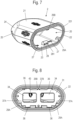
- Figur 8
- eine Draufsicht auf die Kamerahalterung auf die Stirnfläche, die am Fahrzeugaufbau befestigt wird,
- Figur 9
- eine Draufsicht auf die Kamerahalterung von der Frontseite her,
- Figur 10
- eine Schnittdarstellung durch die in
Figur 9 mit X bezeichnete Schnittebene zur Darstellung von Führungskonturen des Hüllgehäuses und des Kameraträgerteils, - Figuren 11 bis 13
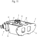
- isometrische Darstellungen einer mit zwei Kameras bestückten alternativen Ausführungsvariante eines Kameraträgerteil aus unterschiedlichen Perspektiven,
- Figur 14
- eine isometrische Darstellung des Kameraträgerteils gemäß
Figuren 11 bis 13 und der Kameras vor deren Einsetzen in das Kameraträgerteil und - Figur 15
- eine Draufsicht auf die in den
Figuren 11 bis 13 gezeigte Anordnung. - In der nachfolgenden Figurenbeschreibung beziehen sich Begriffe wie oben, unten, links, rechts, vorne, hinten usw. ausschließlich auf die in den jeweiligen Figuren gewählte beispielhafte Darstellung und Position der Kamerahalterung, Kameraträgerteil, Hüllgehäuse, Aufnahmeschacht, Fensteröffnung und dergleichen. Diese Begriffe sind nicht einschränkend zu verstehen, d.h., durch verschiedene Arbeitsstellungen oder die spiegelsymmetrische Auslegung oder dergleichen können sich diese Bezüge ändern.
- In den
Figuren 1 und 2 ist mit dem Bezugszeichen 1 insgesamt eine Ausführungsvariante einer erfindungsgemäßen Kamerahalterung bezeichnet. - Die Kamerahalterung 1 ist dabei an einem Fahrzeugaufbau eines Kraftfahrzeugs, bevorzugt eines Busses oder Nutzfahrzeugs oder an einem Anhänger eines solchen Kraftfahrzeugs oder Nutzfahrzeugs befestigbar, um je nach Anbringungsort am Fahrzeugaufbau Umgebungsbereiche seitlich, hinter oder vor dem Fahrzeugaufbau für den Fahrzeugführer visuell über das Signal einer oder mehrerer in der Kamerahalterung 1 befestigter Kameras, insbesondere Videokameras sichtbar zu machen, die sind.
- Die Kamerahalterung 1 besteht im Wesentlichen aus einem an dem Fahrzeugaufbau fixierbaren Kameraträgerteil 3, wie es auch in den
Figuren 3 - 6 gezeigt ist, sowie einem auf das Kameraträgerteil 3 aufstülpbaren Hüllgehäuse 2, das nach der Fixierung des Kameraträgerteils 3 am Fahrzeugaufbau und dem Einsetzen einer oder im in denFiguren 3 und 4 gezeigten Ausführungsbeispiel zwei Kameras auf das Kameraträgerteil 3 aufgestülpt wird. - Wie in den
Figuren 3 - 6 gezeigt ist, weist das Kameraträgerteil 3 wenigstens einen Aufnahmeschacht 32 zur Aufnahme zumindest eines Kamerakorpus 41 einer Kamera 4 auf. - Bei der hier gezeigten Ausführungsvariante weist das Kameraträgerteil 3 zwei solcher Aufnahmeschächte 32 auf, wobei in jedem der Aufnahmeschächte 32 eine Kamera 4 platzierbar ist.
- Das Hüllgehäuse 2 weist in einem im montierten Zustand den Fahrzeugaufbau berührenden rückseitigen Seite eine Aufnahmeöffnung 20 auf, die der Aufnahme des Kameraträgerteils 3 dient.
- In einem von dem Fahrzeugaufbau entfernten Bereich weist das Hüllgehäuse 2 wenigstens eine in einem Gehäusewandbereich 24 vorgesehene Fensteröffnung 25 auf, gezeigt in
Figur 7 , in oder hinter der ein Objektiv 42 der Kamera 4 positionierbar ist. - Bei der in den
Figuren 1 und 2 gezeigten Ausführungsvariante steht das vordere Ende des Objektivs 42 der Kamera 4 in die Fensteröffnung 25 vor. Die Fensteröffnung 25 ist dementsprechend offen ausgebildet. - Denkbar ist auch, die Fensteröffnung 25 durch ein transparentes Material, beispielsweise ein Glas oder ein durchsichtiger Kunststoff zu verschließen, wobei in diesem Fall der Raum zwischen der Fensteröffnung 25 und dem Kameraträgerteil 3 genügend Raum für die Unterbringung des Objektivs 42 der Kamera 4 lässt.
- Wie in den
Figuren 1 ,3 ,5 und8 dargestellt ist, weist das Kameraträgerteil 3 eine Montagewand 31 auf, die am Fahrzeugaufbau befestigt wird, beispielsweise durch Nieten oder Schrauben, die durch dafür vorgesehene Bohrungen 311 in der Montagewand 31 durchgeführt werden können. - Wie weiter in den
Figuren 3-6 dargestellt ist, ist jeder der Aufnahmeschächte 32 des Kameraträgerteils 3 durch eine Außenwand 33 und eine parallel dazu ausgerichtete Innenwand 34 des Kameraträgerteils 3 begrenzt. - Die Außenwand 33 weist eine sacklochartige Aussparung 331 mit zueinander parallel ausgerichteten Gleitkanten 332 auf. Weiter weist die Innenwand 34 jeweils eine sacklochartige Aussparung 341 mit zueinander parallel ausgerichteten Gleitkanten 342 auf.
- Diese Ausführung ermöglicht ein einfaches Einsetzen einer jeweiligen Kamera 4, wobei die Gleitkanten 332 der Außenwand 33 so weit voneinander beabstandet sind, dass zwischen diesen das Objektiv 42 der Kamera 4 mit seiner Mantelfläche an diesen entlanggleitend einschiebbar ist.
- Die Gleitkanten 342 der jeweiligen Innenwand 34 dienen der Aufnahme des Steckanschlusses 43 der Kamera 4, wobei auch hier der Abstand der parallel zueinander laufenden Gleitkanten 342 dem Durchmesser des Steckanschlusses 43 der Kamera 4 entspricht, so dass eine Mantelfläche des Steckanschlusses 43 an den Gleitkanten 342 entlanggleitend einschiebbar ist.
- Zwischen den beiden jeweiligen Gleitkanten 332, 342 dient ein jeweiliges teilkreisförmiges Auflager der Lagerung des Objektivs 42 bzw. des Steckanschlusses 43 der Kamera 4, so dass die Kamera 4 in einer hier horizontalen Ebene ortsfest fixiert ist.
- Der Abstand zwischen der Innenwand 34 und der Außenwand 33 entspricht bevorzugt der Tiefe des Kamerakorpus 41 der Kamera 4. Als Tiefe des Kamerakorpus 41 wird dabei eine Richtung parallel zur Längsrichtung des Objektivs 41 der jeweiligen Kamera 4 betrachtet.
- In einer alternativen Ausführungsvariante, dargestellt in den
Figuren 11 bis 15 , ist der Kamerakorpus 41 mit seitlich eingebrachten Nuten 44 ausgeführt, die der Aufnahme der zueinander parallel ausgerichteten Gleitkanten 332 einer sacklochartigen Aussparung 331 der Außenwand 33 eines Kameraträgerteils 3' dienen. - Eine Innenwand 34 mit sacklochartigen Aussparung 341 ist bei dieser Ausführungsvariante nicht notwendig, da durch die Halterung des Kamerakorpus 41 in der Außenwand 33 des Kameraträgerteils 3' bereits ebenfalls eine vorbestimmte Ausrichtung und ortsfeste Fixierung der Kamera 4 in der horizontalen Ebene gewährleistet ist.
- Denkbar ist auch die Ausbildung der Außenwand 33 bzw. der Außenwände 33 mit einer Nut zur Aufnahme von seitlich aus dem Kameragehäuse vorstehenden Führungsstegen zur Ortsfixierung der Kamera(s) 4 in der horizontalen Ebene an einem Kameraträgerteil 3' mit wie oben beschriebenen Außenwänden 33.
- Zur einfachen und positionsgenauen Positionierung des Hüllgehäuses 2 auf dem Kameraträgerteil 3 weist das Kameraträgerteil 3 und das Hüllgehäuse 2 jeweils Führungskonturen 26, 29A, 29B, 351, 37A, 37B zur Positionierung des Hüllgehäuses 2 auf dem Kameraträgerteil 3 auf.
- Das Kameraträgerteil 3 und das Hüllgehäuse 2 sind dabei lösbar aneinander befestigbar, bevorzugt arretierbar.
- Abweichend davon kann das Hüllgehäuse 2 an dem Kameraträgerteil 3 auch mittels anderer Befestigungselemente, vorzugsweise Schrauben, montiert werden. In diesem Fall kann eine Arretierung entfallen.
- Die lösbare Arretierbarkeit wird bei der hier gezeigten Ausführungsvariante dadurch verwirklicht, dass das Kameraträgerteil 3 und das Hüllgehäuse 2 durch mehrere lösbare Schnappverbindungen aneinander festgelegt ist.
- Wie beispielsweise in den
Figuren 3-6 und 10 gezeigt, weist das Kameraträgerteil 3 sich von einer rückseitigen Montagewand 31 in Richtung eines frontseitigen Endes erstreckende Rastzungen 36 mit daran angeformten Rastnasen 361 auf. - Die Rastnasen 361 sind im aufgeschobenen Zustand des Hüllgehäuses 2 in jeweilige Rastaufnahmen 27, beispielsweise gezeigt in
Figur 7 , in der Innenseite der Gehäusewand 21 des Hüllgehäuses 2 eingerastet. - Um ein beschädigungsfreies Lösen des Hüllgehäuses 2 vom Kameraträgerteil 3 zu ermöglichen, sind die Rastnasen 361 bevorzugt mit Fasen 362 zum Lösen der Verrastung ab einer vorbestimmten Krafteinwirkung auf das Hüllgehäuse 2 entgegen einer Aufschieberichtung A versehen.
- Zur positionsgenauen Ausrichtung des Hüllgehäuses 2 auf dem Kameraträgerteil 3 ist, wie in den
Figuren 4 und10 zu erkennen ist, aus der Innenseite der Gehäusewand 21 des Hüllgehäuses 2 im Bereich des frontseitigen Endes eine stiftartig ausgebildete Führungskontur 26 angeformt, die im auf das Kameraträgerteil 3 aufgeschobenen Zustand in eine als Ausnehmung ausgebildete Führungskontur 351 in einer frontseitigen Wand 35 des Kameraträgerteils 3 vorsteht. - Wie weiter in
Figur 1 ,5 ,7 und 8 dargestellt ist, ist aus der Innenseite seitlicher Bereiche der Gehäusewand 21 des Hüllgehäuses 2 wenigstens eine als Vorsprung oder Nut ausgebildete Führungskontur 29A, 29B angeformt, die im auf das Kameraträgerteil 3 aufgeschobenen Zustand des Hüllgehäuses 2 in eine als Ausnehmung oder Vorsprung ausgebildete Führungskontur 37A, 37B in der Montagewand 31 des Kameraträgerteils 3 vorsteht. - Die als Vorsprünge ausgebildeten Führungskonturen 29A sind als sich in Aufschieberichtung A erstreckender Vorsprünge ausgebildet, an denen eine jeweilige Aussparung, hier an der Montagewand 31 des Kameraträgerteils 3, sich im aufgeschobenen Zustand abstützt.
- Die Führungskontur 29B, gezeigt in
Figur 8 , ist hier als Nut ausgebildet, die einen an der Montagewand 31 ausgebildeten Vorsprung 37B aufnimmt. - Das Hüllgehäuse 2 ist bis auf die Aufnahmeöffnung 20 und die Fensteröffnungen 25 als geschlossene Hülle ausgebildet. Bei Regen oder beim Waschen des Kraftfahrzeugs kann jedoch Wasser durch die Fensteröffnungen 25 in das Hüllgehäuse 2 eintreten. Die Aufnahmeöffnung 20 ist im montierten Zustand der Kamerahalterung 1 am Fahrzeugaufbau durch die Wand des Fahrzeugaufbaus geschlossen.
- Um hier ein Ansteigen von eintretendem Wasser in den Bereich der in der Kamerahalterung 1 aufgenommenen Kameras 4 zu verhindern, ist bei der hier gezeigten bevorzugten Ausführungsvariante, wie in
Figur 7 undFigur 10 gezeigt ist, ein Boden 23 der Gehäusewand 21 des Hüllgehäuses 2 mit einer Ablauföffnung 28 versehen. - Die Ablauföffnung 28 ist dabei als Loch oder Bohrung im Boden 23 der Gehäusewand 21 ausgebildet.
- Im hier gezeigten bevorzugten Ausführungsbeispiel ist zur Abschirmung der Kamera 4 bzw. der Kameras 4 an einer dem Innenraum des Hüllgehäuses 2 abgewandten Außenseite und einer dem Innenraum des Hüllgehäuses 2 zugewandten Innenseite eine die Ablauföffnung 28 teilweise abschirmende Blende 281, 282 angeordnet. Denkbar ist prinzipiell auch die Anordnung einer solchen Blende nur im Innenraum oder nur im Außenraum.
- Bei der hier gezeigten Ausführungsvariante sind die Blenden 281, 282 am Hüllgehäuse 2 angeformt. Die Blende 281 im Innenraum des Hüllgehäuses 2 ist dabei, wie in
Figur 10 gut zu erkennen ist, zu den Kameras 4 hin geschlossen und zur Aufnahmeöffnung 20 hin offen. - Durch diese Blenden 281, 282 wird verhindert, dass insbesondere beim Waschen, insbesondere mit einem Hochdruckreiniger, möglichst wenig Wasser ins Innere des Hüllgehäuses 2 gelangen kann.
- Die Kameras 4 selbst sind bei dieser Ausführungsvariante wasserdicht ausgeführt, was eine besonders einfache und fehlerfreie Montage der Kamerahalterung 1 am Fahrzeugaufbau ermöglicht.
- Die lösbaren Schnappverbindungen zwischen Kameraträgerteil 3 und Hüllgehäuse 2 dienen im Wesentlichen der Vorfixierung des Hüllgehäuses 2 am Kameraträgerteil 3.
- Das Hüllgehäuse 2 wird bevorzugt nach Befestigung am Kameraträgerteil 3 am Fahrzeugaufbau verklebt. Dazu ist die Aufnahmeöffnung 20 des Hüllgehäuses 2 bevorzugt von einer Dichtlippe 22 zur Anlage am Fahrzeugaufbau umrahmt. Die dem frontseitigen Ende des Hüllgehäuses 2 abgewandte Stirnfläche der Dichtlippe 22 weist dabei bevorzugt eine Nut 221 auf, die der Aufnahme eines Adhäsivs dient.
- So kann nach dem vollständigen Aufschieben des Hüllgehäuses 2 auf das Kameraträgerteil 3 mit in der Nut 221 der Dichtlippe 22 eingebrachtem Kleber das Hüllgehäuse 2 am Fahrzeugaufbau verklebt werden, so dass nach dem Austrocknen des Adhäsivs die Fixierung des Hüllgehäuses 2 im Wesentlichen über die Verklebung am Fahrzeugaufbau erfolgt. Die Schnappverbindungen dienen dabei der Unterstützung der Klebeverbindung.
-
- 1
- Kamerahalterung
- 2
- Hüllgehäuse
- 20
- Aufnahmeöffnung
- 21
- Gehäusewand
- 22
- Dichtlippe
- 221
- Nut
- 23
- Boden
- 24
- Gehäusewandbereich
- 25
- Fensteröffnung
- 26
- Führungskontur
- 27
- Rastaufnahme
- 28
- Ablauföffnung
- 281
- Blende
- 282
- Blende
- 29A, B
- Führungskontur
- 3, 3'
- Kameraträgerteil
- 31
- Montagewand
- 32
- Aufnahmeschacht
- 33
- Außenwand
- 331
- Aussparung
- 332
- Gleitkante
- 34
- Innenwand
- 341
- Aussparung
- 342
- Gleitkante
- 35
- Führungskontur
- 36
- Rastzunge
- 361
- Rastnase
- 362
- Fase
- 37A, B
- Führungskontur
- 4
- Kamera
- 41
- Kamerakorpus
- 42
- Objektiv
- 43
- Steckanschluss
- 44
- Nut
- A
- Aufschieberichtung
Claims (16)
- Kamerahalterung (1) zur Befestigung an einem Fahrzeugaufbau eines Kraftfahrzeugs, insbesondere eines Busses oder Nutzfahrzeugs, oder einem Anhänger des Kraftfahrzeugs, aufweisendein an dem Fahrzeugaufbau fixierbares Kameraträgerteil (3, 3`) mit wenigstens einen Aufnahmeschacht (32) zur Aufnahme zumindest eines Kamerakorpus (41) einer Kamera (4),gekennzeichnet durchein auf das Kameraträgerteil (3, 3`) aufstülpbares Hüllgehäuse (2),wobei das Hüllgehäuse (2)
eine Aufnahmeöffnung (20) zur Aufnahme des Kameraträgerteils (3, 3`) und wenigstens eine in einem Gehäusewandbereich (24) vorgesehene Fensteröffnung (25) aufweist, in oder hinter der ein Objektiv (42) der Kamera (4) positionierbar ist,wobei das Kameraträgerteil (3, 3`) und das Hüllgehäuse (2) jeweils Führungskonturen (26, 29A, 29B, 351, 37A, 37B) zur Positionierung des Hüllgehäuses (2) auf dem Kameraträgerteil (3, 3`) aufweisen,wobei das Kameraträgerteil (3, 3`) und das Hüllgehäuse (2) lösbar aneinander befestigbar sind. - Kamerahalterung (1) nach Anspruch 1, dadurch gekennzeichnet, dass der Aufnahmeschacht (32) durch eine Außenwand (33) und eine parallel dazu ausgerichtete Innenwand (34) des Kameraträgerteils (3) begrenzt ist, wobei die Außenwand (33) und die Innenwand (34) jeweils eine sacklochartige Aussparung (331, 341) mit zueinander parallel ausgerichteten Gleitkanten (332, 342) aufweisen, wobei in der Aussparung (331) der Außenwand (33) das Objektiv (42) und in der Aussparung (341) der Innenwand (33) ein aus einer Rückseite des Kamerakorpus (41) vorstehender Steckanschluss (43) der Kamera (4) aufnehmbar ist, wobei der Kamerakorpus (41) zwischen der Außenwand (33) und der Innenwand (34) aufnehmbar ist.
- Kamerahalterung (1) nach Anspruch 1, dadurch gekennzeichnet, dass der Aufnahmeschacht (32) eine Außenwand (33) aufweist, wobei die Außenwand (33) eine sacklochartige Aussparung (331) mit zueinander parallel ausgerichteten Gleitkanten (332) aufweist, wobei die Gleitkanten (332) in seitliche Nuten (44) des Kamerakorpus (41) vorstehen.
- Kamerahalterung (1) nach einem der vorstehenden Ansprüche, dadurch gekennzeichnet, dass das Kameraträgerteil (3, 3`) zwei winklig zueinander angeordnete Aufnahmeschächte (32) zur Aufnahme jeweils einer Kamera (4) und das Hüllgehäuse (2) zwei Fensteröffnungen (25) in winklig zueinander ausgerichteten Gehäusewandbereichen (24) zur Aufnahme eines Objektivs (42) einer jeweiligen der Kameras (4) aufweist.
- Kamerahalterung (1) nach einem der vorstehenden Ansprüche, dadurch gekennzeichnet, dass das Kameraträgerteil (3, 3`) und das Hüllgehäuse (2) durch mehrere lösbare Schnappverbindungen aneinander festgelegt ist.
- Kamerahalterung (1) nach Anspruch 5, dadurch gekennzeichnet, dass das Kameraträgerteil (3, 3`) sich von einer rückseitigen Montagewand (31) in Richtung eines frontseitigen Endes erstreckende Rastzungen (36) mit daran angeformten Rastnasen (361) aufweist, die im aufgeschobenen Zustand des Hüllgehäuses (2) in jeweilige Rastaufnahmen (27) in der Innenseite einer Gehäusewand (21) des Hüllgehäuses (2) eingerastet sind.
- Kamerahalterung (1) nach Anspruch 6, dadurch gekennzeichnet, dass die Rastnasen (361) mit Fasen (362) zum Lösen der Verrastung ab einer vorbestimmten Krafteinwirkung auf das Hüllgehäuse (2) entgegen einer Aufschieberichtung (A) versehen sind.
- Kamerahalterung (1) nach einem der vorstehenden Ansprüche, dadurch gekennzeichnet, dass aus der Innenseite der Gehäusewand (21) des Hüllgehäuses (2) im Bereich des frontseitigen Endes eine stiftartig ausgebildete Führungskontur (26) angeformt ist, die im auf das Kameraträgerteil (3, 3`) aufgeschobenen Zustand in eine als Ausnehmung ausgebildete Führungskontur (351) in einer frontseitigen Wand (35) des Kameraträgerteils (3, 3`) vorsteht.
- Kamerahalterung (1) nach einem der vorstehenden Ansprüche, dadurch gekennzeichnet, dass aus der Innenseite seitlicher Bereiche der Gehäusewand (21) des Hüllgehäuses (2) wenigstens eine als Vorsprung oder Nut ausgebildete Führungskontur (29A, 29B) angeformt ist, die im auf das Kameraträgerteil (3, 3`) aufgeschobenen Zustand in eine als Ausnehmung oder Vorsprung ausgebildete Führungskontur (37A, 37B) in der Montagewand (31) des Kameraträgerteils (3, 3`) vorsteht.
- Kamerahalterung (1) nach einem der vorstehenden Ansprüche, dadurch gekennzeichnet, dass ein Boden (23) der Gehäusewand (21) des Hüllgehäuses (2) eine Ablauföffnung (28) aufweist.
- Kamerahalterung (1) nach Anspruch 10, dadurch gekennzeichnet, dass an einer dem Innenraum des Hüllgehäuses (2) abgewandten Außenseite und/oder einer dem Innenraum des Hüllgehäuses (2) zugewandten Innenseite eine die Ablauföffnung (28) teilweise abschirmende Blende (281, 282) angeordnet, insbesondere angeformt ist.
- Kamerahalterung (1) nach einem der vorstehenden Ansprüche, dadurch gekennzeichnet, dass die Aufnahmeöffnung (20) des Hüllgehäuses (2) von einer Dichtlippe (22) zur Anlage am Fahrzeugaufbau umrahmt ist.
- Kamerahalterung (1) nach Anspruch 12, dadurch gekennzeichnet, dass die dem frontseitigen Ende des Hüllgehäuses (2) abgewandte Stirnfläche der Dichtlippe (22) eine Nut (221) zur Aufnahme eines Adhäsivs aufweist.
- Kamerahalterung (1) nach einem der vorstehenden Ansprüche, dadurch gekennzeichnet, dass die wenigstens eine in dem Gehäusewandbereich (24) vorgesehene Fensteröffnung (25) durch ein transparentes Material verschlossen ist.
- Kraftfahrzeug, insbesondere Bus oder Nutzfahrzeug, dadurch gekennzeichnet, dass das Kraftfahrzeug wenigstens eine Kamerahalterung (1) nach einem der vorstehenden Ansprüche aufweist.
- Anhänger, insbesondere Nutzfahrzeuganhänger, dadurch gekennzeichnet, dass der Anhänger wenigstens eine Kamerahalterung (1) nach einem der vorstehenden Ansprüche 1 bis 14 aufweist.
Applications Claiming Priority (1)
| Application Number | Priority Date | Filing Date | Title |
|---|---|---|---|
| DE102022105242.7A DE102022105242A1 (de) | 2022-03-07 | 2022-03-07 | Kamerahalterung zur Befestigung an einem Fahrzeugaufbau |
Publications (2)
| Publication Number | Publication Date |
|---|---|
| EP4242067A1 true EP4242067A1 (de) | 2023-09-13 |
| EP4242067B1 EP4242067B1 (de) | 2024-09-04 |
Family
ID=85380786
Family Applications (1)
| Application Number | Title | Priority Date | Filing Date |
|---|---|---|---|
| EP23158180.2A Active EP4242067B1 (de) | 2022-03-07 | 2023-02-23 | Kamerahalterung zur befestigung an einem fahrzeugaufbau |
Country Status (4)
| Country | Link |
|---|---|
| EP (1) | EP4242067B1 (de) |
| DE (1) | DE102022105242A1 (de) |
| ES (1) | ES2992003T3 (de) |
| PL (1) | PL4242067T3 (de) |
Citations (10)
| Publication number | Priority date | Publication date | Assignee | Title |
|---|---|---|---|---|
| DE10357781A1 (de) * | 2002-12-11 | 2004-06-24 | AutoNetworks Technologies, Ltd., Nagoya | Vorrichtung zur Überwachung der Umgebung eines Fahrzeuges |
| WO2004058542A1 (en) | 2002-12-20 | 2004-07-15 | Bendix Commercial Vehicle Systems Llc | Universal camera bracket that allows 180 degree of pitch adjustment |
| FR2893891A1 (fr) * | 2005-11-30 | 2007-06-01 | Valeo Systemes Dessuyage | Dispositif d'assistance a la conduite de vehicule |
| KR20110114092A (ko) * | 2010-04-12 | 2011-10-19 | 김준수 | 자동차용 카메라 내장 샤크안테나 |
| DE102012222905A1 (de) * | 2012-12-12 | 2014-06-12 | Robert Bosch Gmbh | Kameraanordnung und Verfahren zu deren Herstellung |
| WO2015088396A1 (en) | 2013-12-11 | 2015-06-18 | Volvo Truck Corporation | Adjustable bracket and method for mounting a detector on a vehicle |
| JP2016116048A (ja) * | 2014-12-13 | 2016-06-23 | 株式会社ヨコオ | アンテナ装置 |
| JP2018186360A (ja) * | 2017-04-25 | 2018-11-22 | 株式会社ヨコオ | アンテナ装置 |
| DE102018117383A1 (de) * | 2017-07-19 | 2019-01-24 | Ford Global Technologies, Llc | Kameras und kameragehäuse für fahrzeuganhänger |
| DE102019102298A1 (de) * | 2018-01-30 | 2019-08-01 | Hirschmann Car Communication Gmbh | Dachantenne eines Fahrzeuges mit einer Rückfahrkamera |
Family Cites Families (2)
| Publication number | Priority date | Publication date | Assignee | Title |
|---|---|---|---|---|
| DE102014214128B4 (de) | 2014-07-21 | 2016-02-04 | Mekra Lang Gmbh & Co. Kg | Trägervorrichtung für die Befestigung einer bildgebenden Einrichtung eines indirekten Sichtsystems an einem Fahrzeug sowie indirektes Sichtsystem hiermit |
| US10798273B2 (en) | 2018-03-22 | 2020-10-06 | Idis Co., Ltd. | Parking guidance camera apparatus and method of installing the same |
-
2022
- 2022-03-07 DE DE102022105242.7A patent/DE102022105242A1/de not_active Ceased
-
2023
- 2023-02-23 ES ES23158180T patent/ES2992003T3/es active Active
- 2023-02-23 PL PL23158180.2T patent/PL4242067T3/pl unknown
- 2023-02-23 EP EP23158180.2A patent/EP4242067B1/de active Active
Patent Citations (10)
| Publication number | Priority date | Publication date | Assignee | Title |
|---|---|---|---|---|
| DE10357781A1 (de) * | 2002-12-11 | 2004-06-24 | AutoNetworks Technologies, Ltd., Nagoya | Vorrichtung zur Überwachung der Umgebung eines Fahrzeuges |
| WO2004058542A1 (en) | 2002-12-20 | 2004-07-15 | Bendix Commercial Vehicle Systems Llc | Universal camera bracket that allows 180 degree of pitch adjustment |
| FR2893891A1 (fr) * | 2005-11-30 | 2007-06-01 | Valeo Systemes Dessuyage | Dispositif d'assistance a la conduite de vehicule |
| KR20110114092A (ko) * | 2010-04-12 | 2011-10-19 | 김준수 | 자동차용 카메라 내장 샤크안테나 |
| DE102012222905A1 (de) * | 2012-12-12 | 2014-06-12 | Robert Bosch Gmbh | Kameraanordnung und Verfahren zu deren Herstellung |
| WO2015088396A1 (en) | 2013-12-11 | 2015-06-18 | Volvo Truck Corporation | Adjustable bracket and method for mounting a detector on a vehicle |
| JP2016116048A (ja) * | 2014-12-13 | 2016-06-23 | 株式会社ヨコオ | アンテナ装置 |
| JP2018186360A (ja) * | 2017-04-25 | 2018-11-22 | 株式会社ヨコオ | アンテナ装置 |
| DE102018117383A1 (de) * | 2017-07-19 | 2019-01-24 | Ford Global Technologies, Llc | Kameras und kameragehäuse für fahrzeuganhänger |
| DE102019102298A1 (de) * | 2018-01-30 | 2019-08-01 | Hirschmann Car Communication Gmbh | Dachantenne eines Fahrzeuges mit einer Rückfahrkamera |
Also Published As
| Publication number | Publication date |
|---|---|
| PL4242067T3 (pl) | 2024-11-04 |
| ES2992003T3 (es) | 2024-12-05 |
| EP4242067B1 (de) | 2024-09-04 |
| DE102022105242A1 (de) | 2023-09-07 |
Similar Documents
| Publication | Publication Date | Title |
|---|---|---|
| EP2674331B1 (de) | Aufnahmevorrichtung | |
| DE10351363A1 (de) | Kameraanordnung für Kraftfahrzeuge | |
| DE102021115338B4 (de) | Dachanordnung, Dachmodul und Kraftfahrzeug mit einer Dichtungsanordnung | |
| DE102008012033A1 (de) | Kraftfahrzeug mit einer Kamera | |
| EP3686062A1 (de) | Vorrichtung für ein kraftfahrzeug | |
| DE102022124290B4 (de) | Dachmodul zur Bildung eines Fahrzeugdachs | |
| DE102019102298A1 (de) | Dachantenne eines Fahrzeuges mit einer Rückfahrkamera | |
| DE202015100385U1 (de) | Sensorhalterung für Fahrzeuge | |
| DE69912049T2 (de) | Montagevorrichtung für den Türgriff einer Fahrzeugtür | |
| DE102019108882A1 (de) | Halterungsbasisteil zur Befestigung wenigstens eines Kameragehäuses an einem Fahrzeugteil eines Fahrzeugs, Kameragehäuse und Kamerasystem | |
| DE112019007621T5 (de) | Kameramodul für Fahrzeuge | |
| DE102022102787A1 (de) | Öffnungs- und Schließvorrichtung für ein Kraftfahrzeug | |
| DE102022127406A1 (de) | Stoßfänger und Stoßfängerbaukasten | |
| DE102021115334B4 (de) | Dachmodul zur Bildung eines Fahrzeugdachs mit einem Sensormodul | |
| EP4242067B1 (de) | Kamerahalterung zur befestigung an einem fahrzeugaufbau | |
| DE102019104251A1 (de) | Halterstruktur für elektronische Bordvorrichtungen | |
| DE102018008105B4 (de) | Kraftfahrzeugemblem mit integrierter Sensor- und Reinigungsvorrichtung | |
| EP3616967B1 (de) | Fahrzeugbedienvorrichtung sowie verfahren zum ändern des anzeigewinkels einer bedien- und anzeigeeinrichtung einer derartigen fahrzeugbedienvorrichtung | |
| EP4242066B1 (de) | Kamerahalterung zur befestigung an einem fahrzeugaufbau | |
| DE102017119230B4 (de) | Befestigungssystem zur Befestigung eines Sensors eines Fahrassistenzsystems | |
| DE102019113081B4 (de) | Fahrzeugkamera und Verfahren zum Zusammenbau einer Fahrzeugkamera | |
| DE8712103U1 (de) | Steckdosenhalter für Kraftfahrzeuge | |
| DE102024107697B3 (de) | Stellvorrichtung | |
| DE102023109818B3 (de) | Sensormodul zur Anordnung an einem Kraftfahrzeug | |
| DE9404411U1 (de) | Anordnung zum Befestigen eines elektronischen Registriergerätes |
Legal Events
| Date | Code | Title | Description |
|---|---|---|---|
| PUAI | Public reference made under article 153(3) epc to a published international application that has entered the european phase |
Free format text: ORIGINAL CODE: 0009012 |
|
| STAA | Information on the status of an ep patent application or granted ep patent |
Free format text: STATUS: THE APPLICATION HAS BEEN PUBLISHED |
|
| AK | Designated contracting states |
Kind code of ref document: A1 Designated state(s): AL AT BE BG CH CY CZ DE DK EE ES FI FR GB GR HR HU IE IS IT LI LT LU LV MC ME MK MT NL NO PL PT RO RS SE SI SK SM TR |
|
| RAP3 | Party data changed (applicant data changed or rights of an application transferred) |
Owner name: KNORR-BREMSE SYSTEME FUER NUTZFAHRZEUGE GMBH |
|
| STAA | Information on the status of an ep patent application or granted ep patent |
Free format text: STATUS: REQUEST FOR EXAMINATION WAS MADE |
|
| 17P | Request for examination filed |
Effective date: 20240313 |
|
| RBV | Designated contracting states (corrected) |
Designated state(s): AL AT BE BG CH CY CZ DE DK EE ES FI FR GB GR HR HU IE IS IT LI LT LU LV MC ME MK MT NL NO PL PT RO RS SE SI SK SM TR |
|
| GRAP | Despatch of communication of intention to grant a patent |
Free format text: ORIGINAL CODE: EPIDOSNIGR1 |
|
| STAA | Information on the status of an ep patent application or granted ep patent |
Free format text: STATUS: GRANT OF PATENT IS INTENDED |
|
| RIC1 | Information provided on ipc code assigned before grant |
Ipc: B60R 11/00 20060101ALN20240405BHEP Ipc: B60R 11/04 20060101AFI20240405BHEP |
|
| INTG | Intention to grant announced |
Effective date: 20240425 |
|
| GRAS | Grant fee paid |
Free format text: ORIGINAL CODE: EPIDOSNIGR3 |
|
| GRAA | (expected) grant |
Free format text: ORIGINAL CODE: 0009210 |
|
| STAA | Information on the status of an ep patent application or granted ep patent |
Free format text: STATUS: THE PATENT HAS BEEN GRANTED |
|
| P01 | Opt-out of the competence of the unified patent court (upc) registered |
Free format text: CASE NUMBER: APP_40226/2024 Effective date: 20240705 |
|
| AK | Designated contracting states |
Kind code of ref document: B1 Designated state(s): AL AT BE BG CH CY CZ DE DK EE ES FI FR GB GR HR HU IE IS IT LI LT LU LV MC ME MK MT NL NO PL PT RO RS SE SI SK SM TR |
|
| REG | Reference to a national code |
Ref country code: GB Ref legal event code: FG4D Free format text: NOT ENGLISH |
|
| REG | Reference to a national code |
Ref country code: CH Ref legal event code: EP |
|
| REG | Reference to a national code |
Ref country code: IE Ref legal event code: FG4D Free format text: LANGUAGE OF EP DOCUMENT: GERMAN |
|
| REG | Reference to a national code |
Ref country code: DE Ref legal event code: R096 Ref document number: 502023000144 Country of ref document: DE |
|
| REG | Reference to a national code |
Ref country code: NL Ref legal event code: FP |
|
| REG | Reference to a national code |
Ref country code: SE Ref legal event code: TRGR |
|
| REG | Reference to a national code |
Ref country code: ES Ref legal event code: FG2A Ref document number: 2992003 Country of ref document: ES Kind code of ref document: T3 Effective date: 20241205 |
|
| REG | Reference to a national code |
Ref country code: LT Ref legal event code: MG9D |
|
| PG25 | Lapsed in a contracting state [announced via postgrant information from national office to epo] |
Ref country code: NO Free format text: LAPSE BECAUSE OF FAILURE TO SUBMIT A TRANSLATION OF THE DESCRIPTION OR TO PAY THE FEE WITHIN THE PRESCRIBED TIME-LIMIT Effective date: 20241204 |
|
| PG25 | Lapsed in a contracting state [announced via postgrant information from national office to epo] |
Ref country code: GR Free format text: LAPSE BECAUSE OF FAILURE TO SUBMIT A TRANSLATION OF THE DESCRIPTION OR TO PAY THE FEE WITHIN THE PRESCRIBED TIME-LIMIT Effective date: 20241205 Ref country code: FI Free format text: LAPSE BECAUSE OF FAILURE TO SUBMIT A TRANSLATION OF THE DESCRIPTION OR TO PAY THE FEE WITHIN THE PRESCRIBED TIME-LIMIT Effective date: 20240904 |
|
| PG25 | Lapsed in a contracting state [announced via postgrant information from national office to epo] |
Ref country code: BG Free format text: LAPSE BECAUSE OF FAILURE TO SUBMIT A TRANSLATION OF THE DESCRIPTION OR TO PAY THE FEE WITHIN THE PRESCRIBED TIME-LIMIT Effective date: 20240904 |
|
| PG25 | Lapsed in a contracting state [announced via postgrant information from national office to epo] |
Ref country code: LV Free format text: LAPSE BECAUSE OF FAILURE TO SUBMIT A TRANSLATION OF THE DESCRIPTION OR TO PAY THE FEE WITHIN THE PRESCRIBED TIME-LIMIT Effective date: 20240904 |
|
| PG25 | Lapsed in a contracting state [announced via postgrant information from national office to epo] |
Ref country code: HR Free format text: LAPSE BECAUSE OF FAILURE TO SUBMIT A TRANSLATION OF THE DESCRIPTION OR TO PAY THE FEE WITHIN THE PRESCRIBED TIME-LIMIT Effective date: 20240904 |
|
| PG25 | Lapsed in a contracting state [announced via postgrant information from national office to epo] |
Ref country code: RS Free format text: LAPSE BECAUSE OF FAILURE TO SUBMIT A TRANSLATION OF THE DESCRIPTION OR TO PAY THE FEE WITHIN THE PRESCRIBED TIME-LIMIT Effective date: 20241204 |
|
| PG25 | Lapsed in a contracting state [announced via postgrant information from national office to epo] |
Ref country code: RS Free format text: LAPSE BECAUSE OF FAILURE TO SUBMIT A TRANSLATION OF THE DESCRIPTION OR TO PAY THE FEE WITHIN THE PRESCRIBED TIME-LIMIT Effective date: 20241204 Ref country code: NO Free format text: LAPSE BECAUSE OF FAILURE TO SUBMIT A TRANSLATION OF THE DESCRIPTION OR TO PAY THE FEE WITHIN THE PRESCRIBED TIME-LIMIT Effective date: 20241204 Ref country code: LV Free format text: LAPSE BECAUSE OF FAILURE TO SUBMIT A TRANSLATION OF THE DESCRIPTION OR TO PAY THE FEE WITHIN THE PRESCRIBED TIME-LIMIT Effective date: 20240904 Ref country code: HR Free format text: LAPSE BECAUSE OF FAILURE TO SUBMIT A TRANSLATION OF THE DESCRIPTION OR TO PAY THE FEE WITHIN THE PRESCRIBED TIME-LIMIT Effective date: 20240904 Ref country code: GR Free format text: LAPSE BECAUSE OF FAILURE TO SUBMIT A TRANSLATION OF THE DESCRIPTION OR TO PAY THE FEE WITHIN THE PRESCRIBED TIME-LIMIT Effective date: 20241205 Ref country code: FI Free format text: LAPSE BECAUSE OF FAILURE TO SUBMIT A TRANSLATION OF THE DESCRIPTION OR TO PAY THE FEE WITHIN THE PRESCRIBED TIME-LIMIT Effective date: 20240904 Ref country code: BG Free format text: LAPSE BECAUSE OF FAILURE TO SUBMIT A TRANSLATION OF THE DESCRIPTION OR TO PAY THE FEE WITHIN THE PRESCRIBED TIME-LIMIT Effective date: 20240904 |
|
| PG25 | Lapsed in a contracting state [announced via postgrant information from national office to epo] |
Ref country code: IS Free format text: LAPSE BECAUSE OF FAILURE TO SUBMIT A TRANSLATION OF THE DESCRIPTION OR TO PAY THE FEE WITHIN THE PRESCRIBED TIME-LIMIT Effective date: 20250104 Ref country code: PT Free format text: LAPSE BECAUSE OF FAILURE TO SUBMIT A TRANSLATION OF THE DESCRIPTION OR TO PAY THE FEE WITHIN THE PRESCRIBED TIME-LIMIT Effective date: 20250106 |
|
| PGFP | Annual fee paid to national office [announced via postgrant information from national office to epo] |
Ref country code: DE Payment date: 20250226 Year of fee payment: 3 |
|
| PG25 | Lapsed in a contracting state [announced via postgrant information from national office to epo] |
Ref country code: SM Free format text: LAPSE BECAUSE OF FAILURE TO SUBMIT A TRANSLATION OF THE DESCRIPTION OR TO PAY THE FEE WITHIN THE PRESCRIBED TIME-LIMIT Effective date: 20240904 Ref country code: RO Free format text: LAPSE BECAUSE OF FAILURE TO SUBMIT A TRANSLATION OF THE DESCRIPTION OR TO PAY THE FEE WITHIN THE PRESCRIBED TIME-LIMIT Effective date: 20240904 |
|
| PGFP | Annual fee paid to national office [announced via postgrant information from national office to epo] |
Ref country code: ES Payment date: 20250314 Year of fee payment: 3 |
|
| PGFP | Annual fee paid to national office [announced via postgrant information from national office to epo] |
Ref country code: SE Payment date: 20250224 Year of fee payment: 3 |
|
| PG25 | Lapsed in a contracting state [announced via postgrant information from national office to epo] |
Ref country code: EE Free format text: LAPSE BECAUSE OF FAILURE TO SUBMIT A TRANSLATION OF THE DESCRIPTION OR TO PAY THE FEE WITHIN THE PRESCRIBED TIME-LIMIT Effective date: 20240904 |
|
| PG25 | Lapsed in a contracting state [announced via postgrant information from national office to epo] |
Ref country code: CZ Free format text: LAPSE BECAUSE OF FAILURE TO SUBMIT A TRANSLATION OF THE DESCRIPTION OR TO PAY THE FEE WITHIN THE PRESCRIBED TIME-LIMIT Effective date: 20240904 |
|
| PGFP | Annual fee paid to national office [announced via postgrant information from national office to epo] |
Ref country code: FR Payment date: 20250224 Year of fee payment: 3 Ref country code: PL Payment date: 20250205 Year of fee payment: 3 |
|
| PG25 | Lapsed in a contracting state [announced via postgrant information from national office to epo] |
Ref country code: SK Free format text: LAPSE BECAUSE OF FAILURE TO SUBMIT A TRANSLATION OF THE DESCRIPTION OR TO PAY THE FEE WITHIN THE PRESCRIBED TIME-LIMIT Effective date: 20240904 |
|
| REG | Reference to a national code |
Ref country code: DE Ref legal event code: R097 Ref document number: 502023000144 Country of ref document: DE |
|
| PG25 | Lapsed in a contracting state [announced via postgrant information from national office to epo] |
Ref country code: DK Free format text: LAPSE BECAUSE OF FAILURE TO SUBMIT A TRANSLATION OF THE DESCRIPTION OR TO PAY THE FEE WITHIN THE PRESCRIBED TIME-LIMIT Effective date: 20240904 |
|
| PLBE | No opposition filed within time limit |
Free format text: ORIGINAL CODE: 0009261 |
|
| STAA | Information on the status of an ep patent application or granted ep patent |
Free format text: STATUS: NO OPPOSITION FILED WITHIN TIME LIMIT |
|
| 26N | No opposition filed |
Effective date: 20250605 |
|
| PG25 | Lapsed in a contracting state [announced via postgrant information from national office to epo] |
Ref country code: MC Free format text: LAPSE BECAUSE OF FAILURE TO SUBMIT A TRANSLATION OF THE DESCRIPTION OR TO PAY THE FEE WITHIN THE PRESCRIBED TIME-LIMIT Effective date: 20240904 |
|
| PG25 | Lapsed in a contracting state [announced via postgrant information from national office to epo] |
Ref country code: LU Free format text: LAPSE BECAUSE OF NON-PAYMENT OF DUE FEES Effective date: 20250223 |
|
| REG | Reference to a national code |
Ref country code: BE Ref legal event code: MM Effective date: 20250228 |
|
| PG25 | Lapsed in a contracting state [announced via postgrant information from national office to epo] |
Ref country code: BE Free format text: LAPSE BECAUSE OF NON-PAYMENT OF DUE FEES Effective date: 20250228 |
|
| PG25 | Lapsed in a contracting state [announced via postgrant information from national office to epo] |
Ref country code: IE Free format text: LAPSE BECAUSE OF NON-PAYMENT OF DUE FEES Effective date: 20250223 |
|
| PGFP | Annual fee paid to national office [announced via postgrant information from national office to epo] |
Ref country code: AT Payment date: 20260301 Year of fee payment: 4 |
|
| PGFP | Annual fee paid to national office [announced via postgrant information from national office to epo] |
Ref country code: IT Payment date: 20260228 Year of fee payment: 4 |