EP4241889B1 - Vorrichtung zum zerkleinern von glas - Google Patents
Vorrichtung zum zerkleinern von glas Download PDFInfo
- Publication number
- EP4241889B1 EP4241889B1 EP23160555.1A EP23160555A EP4241889B1 EP 4241889 B1 EP4241889 B1 EP 4241889B1 EP 23160555 A EP23160555 A EP 23160555A EP 4241889 B1 EP4241889 B1 EP 4241889B1
- Authority
- EP
- European Patent Office
- Prior art keywords
- crushing
- bottle
- glass
- opening
- crushing device
- Prior art date
- Legal status (The legal status is an assumption and is not a legal conclusion. Google has not performed a legal analysis and makes no representation as to the accuracy of the status listed.)
- Active
Links
Images


Classifications
-
- B—PERFORMING OPERATIONS; TRANSPORTING
- B02—CRUSHING, PULVERISING, OR DISINTEGRATING; PREPARATORY TREATMENT OF GRAIN FOR MILLING
- B02C—CRUSHING, PULVERISING, OR DISINTEGRATING IN GENERAL; MILLING GRAIN
- B02C19/00—Other disintegrating devices or methods
- B02C19/0056—Other disintegrating devices or methods specially adapted for specific materials not otherwise provided for
- B02C19/0081—Other disintegrating devices or methods specially adapted for specific materials not otherwise provided for specially adapted for breaking-up bottles
- B02C19/0087—Other disintegrating devices or methods specially adapted for specific materials not otherwise provided for specially adapted for breaking-up bottles for glass bottles
-
- B—PERFORMING OPERATIONS; TRANSPORTING
- B02—CRUSHING, PULVERISING, OR DISINTEGRATING; PREPARATORY TREATMENT OF GRAIN FOR MILLING
- B02C—CRUSHING, PULVERISING, OR DISINTEGRATING IN GENERAL; MILLING GRAIN
- B02C1/00—Crushing or disintegrating by reciprocating members
- B02C1/02—Jaw crushers or pulverisers
- B02C1/04—Jaw crushers or pulverisers with single-acting jaws
Definitions
- the present invention relates to the field of domestic management of used glass containers, and more particularly to domestic glass crushing equipment.
- Used glass bottles and jars represent significant volumes of household waste, which must be transported in dedicated containers and which in the meantime clutter up living space.
- the aim is to reduce the volume of this waste and to facilitate its disposal and transfer to containers for glass items.
- the orderly individual provides a box at home to store them in bulk while waiting for grouped transport. This box fills up quickly because the empty bottles of different sizes and not stored take up volume. Once the box is full, the individual will be confronted with the weight, the absence of carrying handles and the bulk of the box, when leaving the house, and when arriving at the dumpster to load and unload it from the car trunk. The individual must then do the opposite to insert bottle by bottle into the inspection chamber of the glass recycling bin.
- the patent DE6934677 proposes a bottle crushing system comprising a control device for actuating the clamping and triggering device of the striker and the low tilting grid is designed as a lever linkage, which consists of two articulated control rods connected to each other, at the articulation point of which another control rod acts, the lower free end of which is fixed to a pivoting lever on the articulated pivoting grid and which is connected to the pivoting lever and to one of the first two control rods in such a way that the pivoting grid has a closed position when the pivoting hood is open, and one of the two aforementioned control rods comprises a control rod with its free end at the linkage
- the patent DE9106481 relates to another example of a glass crusher, characterized in that glass bottles or other glass containers are crushed in a mechanically or electromechanically operated device.
- the invention relates, in its most general sense, to a glass crushing device having the characteristics set out in claim 1.
- It consists of a grinding head having an opening on the upper surface, for the introduction of bottles, characterized in that said grinding head has a lower opening opening into a removable cartridge collector.
- said crushing head comprises a hollow tilting box having a cutout for the passage of a bottle and having on its lower surface a keel for the bursting of a bottle.
- said grinding head comprises a hollow tilting box having a square section, open at the front frontal end.
- the upper face of said hollow box has in its front part a cutout which is positioned at rest under the opening for the introduction of the bottle and, at the rear of this cutout a deflector standing vertically, to direct the bottle passing through the opening in the box.
- said opening for the introduction of bottles has rubber lips ensuring closure and preventing the projection of splinters.
- said grinding head has an arched rear face with a slot for the passage of the lever for actuating the grinding box.
- said grinding head comprises a container having a base on which the bottle to be ground will rest, and opening with a cutout for the passage of the ground material towards a neck directing the ground material towards the cartridge collector.
- said grinding head is mounted on a support provided with a base.
- said grinding head comprises a fixing lug for wall mounting.
- the device further comprises a sensor capable of detecting the crushing of a bottle as well as a means of recording on a physical or digital medium the outcome of a crushing.
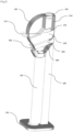
- THE figures 1 And 2 represent an overview of an example of a glass crushing device according to the invention.
- the generic term "glass” is included in the definition in the recycling instructions, designating the various glass waste: standard-sized bottles of beer, wine, cider, champagne, etc., but also canned food glass, sauce in standard sizes that can be broken and recycled, excluding crockery glasses, dishes, plates and light bulb glasses as well as all metal and plastic container closure elements not provided for recycling in the bin provided in town for this purpose.
- It consists of a support (100), for example a metal profile, having at its lower part a base (101) ensuring stability. It comprises a crushing head (200) having an opening (201) at the upper surface, for the introduction of the bottles to be treated. It can be closed by a cap outside periods of use.
- the foot size and the cartridge collector size can be adapted to a disabled person to adjust the height of the opening to the reach of a person in a wheelchair for example.
- This opening advantageously has rubber lips ensuring a watertight closure and preventing the projection of splinters and preventing the introduction of the hand. It also has a handle for operating the grinding system, operated manually and not by an electric motor.
- the crushed material is collected in a cartridge collector (150) in the form of a hollow column, resting on the base (101) and housed under the grinding head (200).
- cartridge collector Once the cartridge collector is full, it is separated from the support (100) to be capped. A new empty cartridge collector can be inserted so that the equipment can continue to operate, while the first one is emptied.
- Full cartridge collectors can be stored or transported to the city's glass recycling bin. The user simply unscrews or removes the cartridge cap to insert it into the circular opening of the bin.
- a handle that makes it easier to tilt the cartridge collector and prevents it from accidentally falling into the glass bin provides valuable assistance to the user.
- the cap will be replaced once this operation is complete.
- FIG 3 shows a detailed view of the grinding head (200). It is made of a material, for example stainless steel, in the form of a box (251) of square section for example, open at one of the front ends and closed at the other.
- a material for example stainless steel
- the upper face has in its front part a cutout (253) which is positioned under the opening (201) for the introduction of the bottle. At the rear of this cutout (253), there is a deflector (254) standing vertically, and which cuts the bottle when the control handle is lifted. The partially crushed bottle passes through the opening (210) and goes into the box (251).
- the grinding head has on the lower surface (255) of the box (251) a rigid keel (260), made of steel for example, having an inclined front face (261) and an arched rear face (262) having a radius of curvature corresponding to that of the rear edge (205) of the shell of the grinding head (200).
- the box (250) is crossed by a pivot axis (270) located above the upper face (256) of the hollow box (250).
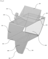
- FIG 4 represents a view of the inside of the grinding head (200). It has an arched rear face (205) with a slot (206) for the passage of the lever for actuating the grinding box (250). It comprises a deflector (207) extending vertically to orient the bottles introduced into the opening (201). A pivot (208) ensures the pivoting of the box (250) by crossing its pivot axis (270).
- the lower part has a solid steel tray (220) having a bottom (221) on which the bottle to be crushed will rest, and opening by a cutout (222) for the passage of the crushed material towards a neck (230) directing the crushed material towards the cartridge collector (150).
- This neck (230) has a defined length to allow the installation and removal of the cartridge collector (150) which is wedged between a cavity formed in the base (101) and the neck (230) which is engaged in its opening.
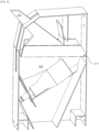
- the crushing box (250) is positioned horizontally, the handle (201) being at the bottom of the slide (206).
- the bottle (1) is introduced by passing through the orifice (201) and enters the hollow box (250) in which it is placed (position of the small bottle shown in dotted lines on the figure 5 ). This is particularly the case for small fragile bottles (beer bottles for example).
- the handle (201) is then moved upwards, and the box (250) tilts into a vertical position, which allows the bottle (1) to slide onto the tray (220), formed of two triangular rails, so that the bottle is naturally placed in the axis of the edge of the keel (260).
- the box (250) tilts in the other direction (box hatched on the figure 5 ), and the keel (260) exerts pressure on the bottle (1) held in the tank (220), which causes it to burst.
- the dimensions of the keel (260) are determined so that its lower surface is sufficient to pass through the slot (222) formed in the tank (220) during its rotation, in order to sweep the slot (222) and prevent the formation of glass plugs that would block it during the next use.
- the shards pass through the cutout (222) and fall into the cartridge collector (250).
- the bottle cannot pass through the tilting box (250) due to their size (position of the large bottle shown in dotted lines on the figure 5 ).
- the blade (254) when lifting the control handle, breaks the "large bottle” for the first time and then enters the box (250) and then follows the same treatment as a "small bottle”. This phase is important because it allows the "large bottles" to be broken at their weak point.
- the gauge (301) is a sliding rod held raised by a spring and entering the upper opening of the cartridge collector (150).
- the gauge (301) is not blocked in its descent. The user can thus check the filling level by pressing the gauge (301) whenever he wishes. If the rod retracts completely, the cartridge collector (150) can still be filled. If on the contrary the rod, during a pushing action by the user, is stopped during its travel by the glass level of the cartridge collector (150), it is then time to plug the full cartridge collector (screw cap type) and replace it with an empty one.
- the cartridge collector once capped by the device, is then completely waterproof and easy to transport (back strap/handle for handling).
- the connecting plate (215) between the foot (150) and the grinder (200) can also be fixed to the wall with a "triangle wedge".
- the grinder can be hung without the foot, which is not necessary for this application.
- FIG 7 illustrates an alternative embodiment of a device that is not mounted on a stand, but hung on a wall.
- the grinding head (200) has an extension (215) allowing screwing onto a wall.
- the cartridge collector (150) is held under the grinding head by hooking or screwing, or by a bayonet engagement system.
- the device comprises a sensor for detecting the completion of a crushing operation and a means for recording on a physical or digital medium information justifying the completion of a crushing operation.
- a sensor for detecting the completion of a crushing operation and a means for recording on a physical or digital medium information justifying the completion of a crushing operation.
- Such a device can be installed in a public space or at a retailer's to encourage the public to return glass bottles by providing a commercial advantage, in the form of a discount coupon for example or recording a bonus on a loyalty card.
- the sensor is for example a force sensor placed under the cradle (220), which triggers a signal when the pressure exerted by the bottle on the cradle (220) due to the force exerted by the keel (260) exceeds a threshold value.
- the recording means may be a print head associated with a ticket feeder, or a mini-printer delivering a printed coupon, or a memory card interface, allowing the user to use a loyalty card for example.
- the device can be equipped with an electric, pneumatic or hydraulic motor providing assistance in tilting the grinding head (200).
- the Figures 8 And 9 represent another embodiment variant respectively in the waiting position and in the casing position.
- the handle (210) and the keel (260) form a single metal part articulated relative to a transverse pivot (211) on the side opposite the handle to form a lever arm amplifying the force exerted for crushing.
- the edge of the keel (260) can be grooved or coated with tungsten or other solid metal shot or points to prevent the bottle from slipping.
- the front part of the bottle receiving cradle may have an opening to allow the passage of the neck of large bottles, for example champagne bottles.
Landscapes
- Engineering & Computer Science (AREA)
- Food Science & Technology (AREA)
- Mechanical Engineering (AREA)
- Disintegrating Or Milling (AREA)
Claims (9)
- Einrichtung zum Zerkleinern von Glas, bestehend aus einem Träger (100) und einem Zerkleinerungskopf (200), der eine Öffnung (201) an der oberen Oberfläche für die Einführung von Flaschen aufweist,
dadurch gekennzeichnet, dass der Zerkleinerungskopf (200) eine untere Öffnung aufweist, die in einen abnehmbaren Kartuschensammler (150) mündet, und dadurch, dass der Zerkleinerungskopf (200) einen hohlen Kippkasten (250) umfasst, der einen Ausschnitt (253) für den Durchgang einer Flasche (1) aufweist, und an seiner unteren Oberfläche einen Kiel (260) für das Zersplittern einer Flasche (1) aufweist. - Einrichtung zum Zerkleinern von Glas nach dem vorstehenden Anspruch, dadurch gekennzeichnet, dass der Zerkleinerungskopf (200) einen hohlen Kippkasten (250), der einen quadratischen Querschnitt aufweist, der an dem vorderen Stirnende offen ist, umfasst.
- Einrichtung zum Zerkleinern von Glas nach dem vorstehenden Anspruch, dadurch gekennzeichnet, dass die obere Fläche des hohlen Kastens (250) in ihrem vorderen Teil einen Ausschnitt (253) aufweist, und im Ruhezustand unter der Öffnung (201) für die Einführung der Flasche und an der Rückseite dieses Ausschnitts (253) ein vertikal stehender Ablenker (254) positioniert ist, um die durch die Öffnung (210) hindurchtretende Flasche in den Kasten (250) zu leiten.
- Einrichtung zum Zerkleinern von Glas nach Anspruch 1,
dadurch gekennzeichnet, dass die Öffnung (201) für die Einführung der Flaschen (1) Gummilippen aufweist, die den Verschluss gewährleisten und das Herausschleudern von Splittern verhindern. - Einrichtung zum Zerkleinern von Glas nach Anspruch 1,
dadurch gekennzeichnet, dass der Zerkleinerungskopf (200) eine bogenförmige rückseitige Fläche (205) mit einem Schlitz (206) für den Durchgang des Betätigungshebels eines Zerkleinerungskastens (250) aufweist. - Einrichtung zum Zerkleinern von Glas nach Anspruch 1,
dadurch gekennzeichnet, dass der Zerkleinerungskopf (200) einen Behälter (220), der einen Boden (221) aufweist, auf dem die zu zerkleinernde Flasche ruht, und der sich durch einen Ausschnitt (222) für den Durchgang der Zerkleinerungsstücke zu einem Hals (230) hin öffnet, der die Zerkleinerungsstücke zu dem Kartuschensammler (150) hin leitet. - Einrichtung zum Zerkleinern von Glas nach Anspruch 1,
dadurch gekennzeichnet, dass der Zerkleinerungskopf (200) auf einem Träger (100) montiert ist, der mit einem Sockel (101) versehen ist. - Einrichtung zum Zerkleinern von Glas nach Anspruch 1,
dadurch gekennzeichnet, dass der Zerkleinerungskopf (200) eine Befestigungslasche (215) für eine Wandaufhängung aufweist. - Einrichtung zum Zerkleinern von Glas nach Anspruch 1,
dadurch gekennzeichnet, dass sie einen Sensor, der geeignet ist, das Zerkleinern einer Flasche zu erfassen, sowie ein Mittel zum Aufzeichnen des Ergebnisses einer Zerkleinerung auf einem physischen oder digitalen Träger umfasst.
Applications Claiming Priority (1)
| Application Number | Priority Date | Filing Date | Title |
|---|---|---|---|
| FR2201947A FR3133145A1 (fr) | 2022-03-07 | 2022-03-07 | Dispositif de broyage de verre |
Publications (3)
| Publication Number | Publication Date |
|---|---|
| EP4241889A1 EP4241889A1 (de) | 2023-09-13 |
| EP4241889C0 EP4241889C0 (de) | 2024-10-30 |
| EP4241889B1 true EP4241889B1 (de) | 2024-10-30 |
Family
ID=82319870
Family Applications (1)
| Application Number | Title | Priority Date | Filing Date |
|---|---|---|---|
| EP23160555.1A Active EP4241889B1 (de) | 2022-03-07 | 2023-03-07 | Vorrichtung zum zerkleinern von glas |
Country Status (2)
| Country | Link |
|---|---|
| EP (1) | EP4241889B1 (de) |
| FR (1) | FR3133145A1 (de) |
Family Cites Families (8)
| Publication number | Priority date | Publication date | Assignee | Title |
|---|---|---|---|---|
| DE1871845U (de) * | 1963-03-06 | 1963-05-09 | Karl Schwarze & Sohn K G | Vorrichtung zur zertruemmerung von flaschen. |
| DE6934677U (de) * | 1969-09-02 | 1970-01-02 | Helga Duhnkrack | Vorrichtung zum zerkleinern von gegenstaenden aus glas, insbesondere flaschen |
| US4573641A (en) | 1983-11-17 | 1986-03-04 | Environmental Products Corporation | Glass bottle collection and crushing apparatus |
| DE9106481U1 (de) * | 1991-05-27 | 1991-08-01 | Grafenhorst, Heinrich, Dipl.-Ing., 2800 Bremen | Glaszerkleinerer |
| CH682887A5 (de) | 1991-06-13 | 1993-12-15 | Josef Wild | Vorrichtung zum Zertrümmern von Glasbehältern. |
| DE9211232U1 (de) * | 1992-08-21 | 1992-11-12 | Nord, Klaus Jürgen, 6800 Mannheim | Vorrichtung zum Senken der Geräusche und zum gleichmäßigen Zerkleinern von Altglas in entsprechenden Containern |
| US5350120A (en) | 1993-08-10 | 1994-09-27 | New England Redemption Of Connecticut, Inc. | Method of crushing a bottle and a glass crushing apparatus |
| WO2007031086A1 (en) | 2005-09-13 | 2007-03-22 | Anker Andersen A/S | A glass crusher and use thereof |
-
2022
- 2022-03-07 FR FR2201947A patent/FR3133145A1/fr not_active Withdrawn
-
2023
- 2023-03-07 EP EP23160555.1A patent/EP4241889B1/de active Active
Also Published As
| Publication number | Publication date |
|---|---|
| EP4241889A1 (de) | 2023-09-13 |
| FR3133145A1 (fr) | 2023-09-08 |
| EP4241889C0 (de) | 2024-10-30 |
Similar Documents
| Publication | Publication Date | Title |
|---|---|---|
| FR2479783A1 (fr) | Dispositif pour le basculement de bacs a dechets dans une benne de collecte | |
| FR2687654A1 (fr) | Structure pour permettre de charger ou decharger des marchandises a transporter avec un dispositif de manutention a bras de levage hydraulique. | |
| EP4241889B1 (de) | Vorrichtung zum zerkleinern von glas | |
| FR3013022A1 (fr) | Chariot de transport ameliore | |
| FR3053819B1 (fr) | Distributeur automatique a dispositif de recuperation mobile | |
| FR2683511A1 (fr) | Poubelle compartimentee pour le stockage et le ramassage selectifs de dechets. | |
| WO2013068440A1 (fr) | Poubelle à boissons | |
| FR2664802A1 (fr) | Appareil de distribution automatique de produits en bidons ou autres. | |
| BE1009279A3 (fr) | Dispositif de reception et de tri d'objets divers, notamment de recipients a mettre au rebut. | |
| EP1012090B1 (de) | Präsentations- und orientierungsvorrichtung für einen behälter zur lagerung und entnahme von artikeln | |
| FR2722486A1 (fr) | Conteneur perfectionne | |
| FR2467800A1 (fr) | Dispositif pour limiter la hauteur de remplissage d'un receptacle a charger | |
| EP0082129A1 (de) | Einrichtung zum Speichern, Transportieren und Fördern zylindrischer Gegenstände | |
| EP0194218B1 (de) | Vorrichtung zur automatischen Ausgabe von Gegenständen | |
| FR3010988A1 (fr) | Conteneur de collecte des dechets dote d’un systeme perfectionne de commande d'ouverture/fermeture automatique de trappe de vidage | |
| EP1028073A1 (de) | Lagergestell für Flüssigkeitsballons, insbesondere Wasserballons | |
| FR3020351A1 (fr) | Dispositif de chargement en dechets d'une benne de dechetterie depuis une plateforme | |
| FR2577202A1 (fr) | Casier pour le conditionnement d'un lot d'objets, notamment d'objets lourds et volumineux tels que des bouteilles de gaz liquefie | |
| FR2687131A1 (fr) | Conteneur perfectionne. | |
| EP0754096A1 (de) | Verfahren und vorrichtung zur selektiven sammlung von gegenständen aus glas und zum zeitweiligen lagern ihres stoffes | |
| FR3131285A1 (fr) | Installation de distribution de boissons dans des recipients notamment de type canette | |
| FR2741330A1 (fr) | Mecanisme de basculement de benne | |
| FR3135714A1 (fr) | Appareil distributeur de produit liquide | |
| FR3081852A1 (fr) | Dispositif basculeur pour receptacle a grand angle de basculement | |
| FR2934135A1 (fr) | Casier pour l'emmagasinage et la distribution d'articles et appareil de chargement en articles associe |
Legal Events
| Date | Code | Title | Description |
|---|---|---|---|
| PUAI | Public reference made under article 153(3) epc to a published international application that has entered the european phase |
Free format text: ORIGINAL CODE: 0009012 |
|
| STAA | Information on the status of an ep patent application or granted ep patent |
Free format text: STATUS: REQUEST FOR EXAMINATION WAS MADE |
|
| 17P | Request for examination filed |
Effective date: 20230307 |
|
| AK | Designated contracting states |
Kind code of ref document: A1 Designated state(s): AL AT BE BG CH CY CZ DE DK EE ES FI FR GB GR HR HU IE IS IT LI LT LU LV MC ME MK MT NL NO PL PT RO RS SE SI SK SM TR |
|
| GRAP | Despatch of communication of intention to grant a patent |
Free format text: ORIGINAL CODE: EPIDOSNIGR1 |
|
| STAA | Information on the status of an ep patent application or granted ep patent |
Free format text: STATUS: GRANT OF PATENT IS INTENDED |
|
| RIC1 | Information provided on ipc code assigned before grant |
Ipc: B02C 19/00 20060101ALI20240521BHEP Ipc: B02C 1/04 20060101AFI20240521BHEP |
|
| INTG | Intention to grant announced |
Effective date: 20240607 |
|
| GRAS | Grant fee paid |
Free format text: ORIGINAL CODE: EPIDOSNIGR3 |
|
| GRAA | (expected) grant |
Free format text: ORIGINAL CODE: 0009210 |
|
| STAA | Information on the status of an ep patent application or granted ep patent |
Free format text: STATUS: THE PATENT HAS BEEN GRANTED |
|
| AK | Designated contracting states |
Kind code of ref document: B1 Designated state(s): AL AT BE BG CH CY CZ DE DK EE ES FI FR GB GR HR HU IE IS IT LI LT LU LV MC ME MK MT NL NO PL PT RO RS SE SI SK SM TR |
|
| REG | Reference to a national code |
Ref country code: GB Ref legal event code: FG4D Free format text: NOT ENGLISH |
|
| REG | Reference to a national code |
Ref country code: CH Ref legal event code: EP |
|
| REG | Reference to a national code |
Ref country code: IE Ref legal event code: FG4D Free format text: LANGUAGE OF EP DOCUMENT: FRENCH |
|
| REG | Reference to a national code |
Ref country code: DE Ref legal event code: R096 Ref document number: 602023000847 Country of ref document: DE |
|
| U01 | Request for unitary effect filed |
Effective date: 20241128 |
|
| U07 | Unitary effect registered |
Designated state(s): AT BE BG DE DK EE FI FR IT LT LU LV MT NL PT RO SE SI Effective date: 20241210 |
|
| PG25 | Lapsed in a contracting state [announced via postgrant information from national office to epo] |
Ref country code: IS Free format text: LAPSE BECAUSE OF FAILURE TO SUBMIT A TRANSLATION OF THE DESCRIPTION OR TO PAY THE FEE WITHIN THE PRESCRIBED TIME-LIMIT Effective date: 20250228 Ref country code: HR Free format text: LAPSE BECAUSE OF FAILURE TO SUBMIT A TRANSLATION OF THE DESCRIPTION OR TO PAY THE FEE WITHIN THE PRESCRIBED TIME-LIMIT Effective date: 20241030 |
|
| PG25 | Lapsed in a contracting state [announced via postgrant information from national office to epo] |
Ref country code: ES Free format text: LAPSE BECAUSE OF FAILURE TO SUBMIT A TRANSLATION OF THE DESCRIPTION OR TO PAY THE FEE WITHIN THE PRESCRIBED TIME-LIMIT Effective date: 20241030 |
|
| PG25 | Lapsed in a contracting state [announced via postgrant information from national office to epo] |
Ref country code: NO Free format text: LAPSE BECAUSE OF FAILURE TO SUBMIT A TRANSLATION OF THE DESCRIPTION OR TO PAY THE FEE WITHIN THE PRESCRIBED TIME-LIMIT Effective date: 20250130 |
|
| PG25 | Lapsed in a contracting state [announced via postgrant information from national office to epo] |
Ref country code: GR Free format text: LAPSE BECAUSE OF FAILURE TO SUBMIT A TRANSLATION OF THE DESCRIPTION OR TO PAY THE FEE WITHIN THE PRESCRIBED TIME-LIMIT Effective date: 20250131 |
|
| PG25 | Lapsed in a contracting state [announced via postgrant information from national office to epo] |
Ref country code: PL Free format text: LAPSE BECAUSE OF FAILURE TO SUBMIT A TRANSLATION OF THE DESCRIPTION OR TO PAY THE FEE WITHIN THE PRESCRIBED TIME-LIMIT Effective date: 20241030 |
|
| PG25 | Lapsed in a contracting state [announced via postgrant information from national office to epo] |
Ref country code: RS Free format text: LAPSE BECAUSE OF FAILURE TO SUBMIT A TRANSLATION OF THE DESCRIPTION OR TO PAY THE FEE WITHIN THE PRESCRIBED TIME-LIMIT Effective date: 20250130 |
|
| U20 | Renewal fee for the european patent with unitary effect paid |
Year of fee payment: 3 Effective date: 20250325 |
|
| PG25 | Lapsed in a contracting state [announced via postgrant information from national office to epo] |
Ref country code: SM Free format text: LAPSE BECAUSE OF FAILURE TO SUBMIT A TRANSLATION OF THE DESCRIPTION OR TO PAY THE FEE WITHIN THE PRESCRIBED TIME-LIMIT Effective date: 20241030 |
|
| PG25 | Lapsed in a contracting state [announced via postgrant information from national office to epo] |
Ref country code: SK Free format text: LAPSE BECAUSE OF FAILURE TO SUBMIT A TRANSLATION OF THE DESCRIPTION OR TO PAY THE FEE WITHIN THE PRESCRIBED TIME-LIMIT Effective date: 20241030 |
|
| PG25 | Lapsed in a contracting state [announced via postgrant information from national office to epo] |
Ref country code: CZ Free format text: LAPSE BECAUSE OF FAILURE TO SUBMIT A TRANSLATION OF THE DESCRIPTION OR TO PAY THE FEE WITHIN THE PRESCRIBED TIME-LIMIT Effective date: 20241030 |
|
| PLBE | No opposition filed within time limit |
Free format text: ORIGINAL CODE: 0009261 |
|
| STAA | Information on the status of an ep patent application or granted ep patent |
Free format text: STATUS: NO OPPOSITION FILED WITHIN TIME LIMIT |
|
| 26N | No opposition filed |
Effective date: 20250731 |
|
| PG25 | Lapsed in a contracting state [announced via postgrant information from national office to epo] |
Ref country code: MC Free format text: LAPSE BECAUSE OF FAILURE TO SUBMIT A TRANSLATION OF THE DESCRIPTION OR TO PAY THE FEE WITHIN THE PRESCRIBED TIME-LIMIT Effective date: 20241030 |
|
| PG25 | Lapsed in a contracting state [announced via postgrant information from national office to epo] |
Ref country code: IE Free format text: LAPSE BECAUSE OF NON-PAYMENT OF DUE FEES Effective date: 20250307 |