EP4240948B1 - Montageeinheit für eine turboladeranordnung eines hubkolbenverbrennungsmotors, turboladeranordnung und hubkolbenverbrennungsmotor - Google Patents
Montageeinheit für eine turboladeranordnung eines hubkolbenverbrennungsmotors, turboladeranordnung und hubkolbenverbrennungsmotor Download PDFInfo
- Publication number
- EP4240948B1 EP4240948B1 EP20807820.4A EP20807820A EP4240948B1 EP 4240948 B1 EP4240948 B1 EP 4240948B1 EP 20807820 A EP20807820 A EP 20807820A EP 4240948 B1 EP4240948 B1 EP 4240948B1
- Authority
- EP
- European Patent Office
- Prior art keywords
- pressure
- low
- mounting unit
- heat exchanger
- air channel
- Prior art date
- Legal status (The legal status is an assumption and is not a legal conclusion. Google has not performed a legal analysis and makes no representation as to the accuracy of the status listed.)
- Active
Links
Images

Classifications
-
- F—MECHANICAL ENGINEERING; LIGHTING; HEATING; WEAPONS; BLASTING
- F02—COMBUSTION ENGINES; HOT-GAS OR COMBUSTION-PRODUCT ENGINE PLANTS
- F02B—INTERNAL-COMBUSTION PISTON ENGINES; COMBUSTION ENGINES IN GENERAL
- F02B29/00—Engines characterised by provision for charging or scavenging not provided for in groups F02B25/00, F02B27/00 or F02B33/00 - F02B39/00; Details thereof
- F02B29/04—Cooling of air intake supply
- F02B29/0406—Layout of the intake air cooling or coolant circuit
- F02B29/0412—Multiple heat exchangers arranged in parallel or in series
-
- F—MECHANICAL ENGINEERING; LIGHTING; HEATING; WEAPONS; BLASTING
- F02—COMBUSTION ENGINES; HOT-GAS OR COMBUSTION-PRODUCT ENGINE PLANTS
- F02B—INTERNAL-COMBUSTION PISTON ENGINES; COMBUSTION ENGINES IN GENERAL
- F02B37/00—Engines characterised by provision of pumps driven at least for part of the time by exhaust
- F02B37/013—Engines characterised by provision of pumps driven at least for part of the time by exhaust with exhaust-driven pumps arranged in series
-
- F—MECHANICAL ENGINEERING; LIGHTING; HEATING; WEAPONS; BLASTING
- F02—COMBUSTION ENGINES; HOT-GAS OR COMBUSTION-PRODUCT ENGINE PLANTS
- F02M—SUPPLYING COMBUSTION ENGINES IN GENERAL WITH COMBUSTIBLE MIXTURES OR CONSTITUENTS THEREOF
- F02M35/00—Combustion-air cleaners, air intakes, intake silencers, or induction systems specially adapted for, or arranged on, internal-combustion engines
- F02M35/10—Air intakes; Induction systems
- F02M35/10091—Air intakes; Induction systems characterised by details of intake ducts: shapes; connections; arrangements
- F02M35/10144—Connections of intake ducts to each other or to another device
-
- F—MECHANICAL ENGINEERING; LIGHTING; HEATING; WEAPONS; BLASTING
- F02—COMBUSTION ENGINES; HOT-GAS OR COMBUSTION-PRODUCT ENGINE PLANTS
- F02M—SUPPLYING COMBUSTION ENGINES IN GENERAL WITH COMBUSTIBLE MIXTURES OR CONSTITUENTS THEREOF
- F02M35/00—Combustion-air cleaners, air intakes, intake silencers, or induction systems specially adapted for, or arranged on, internal-combustion engines
- F02M35/10—Air intakes; Induction systems
- F02M35/1015—Air intakes; Induction systems characterised by the engine type
- F02M35/10157—Supercharged engines
-
- F—MECHANICAL ENGINEERING; LIGHTING; HEATING; WEAPONS; BLASTING
- F02—COMBUSTION ENGINES; HOT-GAS OR COMBUSTION-PRODUCT ENGINE PLANTS
- F02M—SUPPLYING COMBUSTION ENGINES IN GENERAL WITH COMBUSTIBLE MIXTURES OR CONSTITUENTS THEREOF
- F02M35/00—Combustion-air cleaners, air intakes, intake silencers, or induction systems specially adapted for, or arranged on, internal-combustion engines
- F02M35/10—Air intakes; Induction systems
- F02M35/1034—Manufacturing and assembling intake systems
- F02M35/10354—Joining multiple sections together
-
- Y—GENERAL TAGGING OF NEW TECHNOLOGICAL DEVELOPMENTS; GENERAL TAGGING OF CROSS-SECTIONAL TECHNOLOGIES SPANNING OVER SEVERAL SECTIONS OF THE IPC; TECHNICAL SUBJECTS COVERED BY FORMER USPC CROSS-REFERENCE ART COLLECTIONS [XRACs] AND DIGESTS
- Y02—TECHNOLOGIES OR APPLICATIONS FOR MITIGATION OR ADAPTATION AGAINST CLIMATE CHANGE
- Y02T—CLIMATE CHANGE MITIGATION TECHNOLOGIES RELATED TO TRANSPORTATION
- Y02T10/00—Road transport of goods or passengers
- Y02T10/10—Internal combustion engine [ICE] based vehicles
- Y02T10/12—Improving ICE efficiencies
Definitions
- the present disclosure relates to turbochargers in connection with reciprocating internal combustion piston engines, and more particularly to a mounting unit for such turbochargers.
- the present disclosure further concerns a turbocharger arrangement and a reciprocating internal combustion piston engine utilizing such a mounting unit.
- Turbochargers are commonly used in connection with reciprocating internal combustion piston engines so as to increase the amount of intake air usable for combustion in a combustion cylinder.
- a turbocharger comprises a turbine rotationally coupled to a compressor such that the turbine, driven by exhaust gasses, drives the compressor so as to charges the intake air flow.
- turbocharges coupled on after another (i.e., in series), are known to have been used for further increasing the pressure to which the intake air is charged. It is also known to use more than one turbocharger coupled in parallel to increase the flow rate of the charged intake air, as it can be seen for instance in documents EP 1717421A2 and WO 2009/147287A1 .
- turbochargers increase the amount of required ducting, which has conventionally resulted in a more complex structure making both assembly and maintenance more difficult for the both the turbochargers and their associated ducting.
- access to any component in the vicinity of the turbochargers and their associated ducting also becomes more limited, further hindering the assembly and maintenance of the associated engine.
- An object of the present disclosure is to provide a mounting unit, a turbocharger arrangement equipped with such a mounting unit and a reciprocating internal combustion piston engine equipped with such a turbocharger arrangement so as to alleviate the above disadvantages.
- the object of the disclosure is achieved by a mounting unit, a turbocharger arrangement and a reciprocating internal combustion piston engine, which are characterized by what is stated in the independent claims.
- the preferred embodiments of the disclosure are disclosed in the dependent claims.
- the disclosure is based on the idea of providing the mounting unit as a single, rigid structure formed at least by a mounting base, a hot low-pressure air channel, a cool low-pressure air channel, a hot high-pressure air channel and a cool high-pressure air channel. Furthermore, at least the low-pressure turbocharger compressor outlet port and the high-pressure turbocharger compressor outlet port are arranged at the mounting base such that a low-pressure turbocharger compressor outlet and a high-pressure turbocharger compressor outlet can be directly coupled thereto, respectively, thereby mounting the low-pressure turbocharger and the high-pressure turbocharger to the mounting unit.
- mounting unit enables rigidly attaching the low-pressure turbocharger and the high-pressure turbocharger to the mounting unit, while simultaneously achieving fluid communication between the hot low-pressure air channel and the low-pressure turbocharger compressor outlet, and the hot high-pressure air channel and the high-pressure turbocharger compressor outlet.
- a mounting unit for a turbocharger arrangement of a reciprocating internal combustion engine is provided
- low-pressure and high-pressure are used relative to each other. That is, a low-pressure entity is intended to be associated with a lower pressure than a corresponding high-pressure entity.
- hot and cool are also used relative to each other That is, a cool entity is intended to be associated with a lower temperature than a corresponding hot entity.
- a hot low-pressure air channel is intended to be associated to an airflow at a relatively higher temperature and a lower pressure than a cool high-pressure air channel
- the mounting unit comprises a longitudinally extending hot low-pressure air channel.
- the hot low-pressure air channel comprises a low-pressure turbocharger compressor outlet port for providing fluid communication between a low-pressure turbocharger compressor outlet and the hot low-pressure air channel.
- the hot low-pressure air channel further comprises a low-pressure heat exchanger inlet port for providing fluid communication between the hot low-pressure air channel and a low-pressure heat exchanger inlet.
- the low-pressure turbocharger compressor outlet port and the low-pressure heat exchanger inlet port may be provided as respective flanges in connection with the associated air channel.
- the mounting unit further comprises a longitudinally extending cool low-pressure air channel.
- the cool low-pressure air channel in turn, comprises a low-pressure heat exchanger outlet port for providing fluid communication between a low-pressure heat exchanger outlet and the cool low-pressure air channel.
- the cool low-pressure air channel further comprises a high-pressure turbocharger compressor inlet port for providing fluid communication between the cool low-pressure air channel and a high-pressure turbocharger compressor inlet.
- the low-pressure heat exchanger outlet port and the high-pressure turbocharger compressor inlet port may be provided as flanges in connection with the associated air channel.
- the mounting unit further comprises a longitudinally extending hot high-pressure air channel.
- the hot high-pressure air channel comprises a high-pressure turbocharger compressor outlet port for providing fluid communication between a high-pressure turbocharger compressor outlet and the hot high-pressure air channel.
- the hot high-pressure air channel further comprises a high-pressure heat exchanger inlet port for providing fluid communication between the hot high-pressure air channel and a high-pressure heat exchanger inlet.
- the high-pressure turbocharger compressor outlet port and the high-pressure heat exchanger inlet port may be provided as flanges in connection with the associated air channel.
- the mounting unit further comprises a longitudinally extending cool high-pressure air channel.
- the cool high-pressure air channel in turn, comprises a high-pressure heat exchanger outlet port for providing fluid communication between a high-pressure heat exchanger outlet and the cool high-pressure air channel.
- the cool high-pressure air channel further comprises a charge air feed port for providing fluid communication between the cool high-pressure air channel and a charge air inlet port of an associated engine.
- the high-pressure heat exchanger outlet port and the charge air feed port for port may be provided as flanges in connection with the associated air channel.
- the mounting unit further comprises a mounting base for attaching at least a low-pressure turbocharger and a high-pressure turbocharger to the mounting unit, most suitably in a rigid manner.
- the mounting base, the hot low-pressure air channel, cool low-pressure air channel, hot high-pressure air channel and the cool high-pressure air channel are provided as a single, rigid structure.
- the mounting unit could be cast as a single piece, which is then subsequently machined so as to obtain planar surfaces where necessary (e.g., the mounting base and ports).
- said air channels are arranged parallel with respect to each other and one next to another in a first lateral direction, transverse to the longitudinal.
- the mounting base is arranged on a side of the mounting unit in a second lateral direction, transverse to the longitudinal and the first lateral directions.
- the mounting base is arranged on a top side of the mounting unit, when in use.
- At least the low-pressure turbocharger compressor outlet port and the high-pressure turbocharger compressor outlet port are arranged at the mounting base.
- the mounting unit is directly couplable with an identical, second mounting unit such that fluid communication between corresponding air channels of the mounting unit and the second mounting unit is achieved, when coupled. That is, fluid communication is achieved between respective hot low-pressure air channels, cool low-pressure air channels, hot high-pressure air channels and cool high-pressure air channels of a first mounting unit and a second mounting unit, when coupled to each other.
- the hot low-pressure air channel, the cool low-pressure air channel, the hot high-pressure and the cool high-pressure air channel are arranged parallel with respect to each other, such that at least one, preferably both, longitudinal ends of said air channels are configured to be directly couplable with a longitudinal end of a corresponding air channel of an identical second mounting unit.
- corresponding air channels of the mounting unit and the second mounting unit form continuous longitudinal air channels, when coupled.
- At least the low-pressure turbocharger compressor outlet port, the high-pressure turbocharger compressor inlet port and the high-pressure turbocharger compressor outlet port are arranged on a same side of the mounting unit with respect to said air channels.
- one or more, preferably all, of the low-pressure heat exchanger inlet port the low-pressure heat exchanger outlet port the high-pressure heat exchanger inlet port and the high-pressure heat exchanger outlet port are arranged at an longitudinal end of their associated air channel. This ensures, that an input or an output of a low-pressure or high-pressure heat exchanger can be coupled to its associated air channel at a longitudinal end of the mounting unit. This is particularly advantageous, because even an assembly of multiple mounting unit will always have a free end at which a heat exchanger can be coupled.
- an additional low-pressure heat exchanger inlet port for providing fluid communication between the hot low-pressure air channel and a low-pressure heat exchanger inlet may be arranged at a side of the mounting unit opposite to the mounting base, with respect to said air channels in the second lateral direction.
- an additional port may be provided at a bottom of the mounting unit, when in use.
- an additional low-pressure heat exchanger outlet port for providing fluid communication between a low-pressure heat exchanger outlet and the cool low-pressure air channel may be arranged at a side of the mounting unit opposite to the mounting base, with respect to said air channels in the second lateral direction.
- an additional port may be provided at a bottom of the mounting unit, when in use.
- an additional high-pressure heat exchanger inlet port for providing fluid communication between the hot high-pressure air channel and a high-pressure heat exchanger inlet may be arranged at a side of the mounting unit opposite to the mounting base, with respect to said air channels in the second lateral direction.
- an additional port may be provided at a bottom of the mounting unit, when in use.
- an additional high-pressure heat exchanger outlet port for providing fluid communication between a high-pressure heat exchanger outlet and the cool high-pressure air channel may be arranged at a side of the mounting unit opposite to the mounting base, with respect to said air channels in the second lateral direction.
- an additional port may be provided at a bottom of the mounting unit, when in use.
- the low-pressure hot air channel and the low-pressure cool air channel are arranged immediately adjacent to each other, whereas the high-pressure hot air channel and the high-pressure cool air channel are arranged immediately adjacent to each other.
- the low-pressure hot air channel and the high-pressure hot air channel are arranged immediately adjacent to each other.
- the high-pressure cool air channel is arranged laterally outermost with respect to the remaining air channels.
- a turbocharger arrangement of a reciprocating internal combustion engine comprises a first mounting unit being a mounting unit according to any the first aspect of the present disclosure, as discussed above.
- the turbocharger arrangement further comprises a first low-pressure turbocharger.
- the first low-pressure turbocharger in turn, comprises a compressor inlet couplable to an air supply.
- the firs low pressure turbocharger further comprises a compressor outlet directly coupled to the low-pressure turbocharger compressor outlet port of the first mounting unit.
- the first low-pressure turbocharger is mounted onto the first mounting unit at the mounting base thereof.
- the turbocharger arrangement further comprises a first low-pressure heat exchanger.
- the first low-pressure heat exchanger in turn, comprises an inlet coupled to the low-pressure heat exchanger inlet port of the first mounting unit.
- the first low-pressure heat exchanger further comprises an outlet coupled to the low-pressure heat exchanger outlet port of the first mounting unit.
- the first low-pressure heat exchanger is configured to cool a low-pressure airflow between the inlet and outlet thereof.
- the first low-pressure heat exchanger inlet and outlet could be directly coupled to the low-pressure heat exchanger inlet port and the low-pressure heat exchanger outlet port of the first mounting unit, respectively.
- either or both of the low-pressure heat exchanger inlet and outlet ports could be provided at a longitudinal end of the first mounting unit. Additional low-pressure heat exchangers may naturally be provided, if necessary.
- the turbocharger arrangement further comprises a first high-pressure turbocharger.
- the first high-pressure turbocharger in turn, comprises a compressor inlet coupled to the high-pressure turbocharger compressor inlet port of the first mounting unit.
- the first high-pressure turbocharger further comprises a compressor outlet directly coupled to the high-pressure turbocharger compressor outlet port of the first mounting unit.
- the first high-pressure turbocharger is mounted onto the first mounting unit at the mounting base thereof.
- the turbocharger arrangement further comprises a first high-pressure heat exchanger.
- the first high-pressure heat exchanger in turn, comprises an inlet coupled to the high-pressure heat exchanger inlet port of the first mounting unit.
- the first high-pressure heat exchanger further comprises an outlet coupled to the high-pressure heat exchanger outlet port of the first mounting unit.
- the first high-pressure heat exchanger is configured to cool a high-pressure airflow between the inlet and outlet thereof.
- the first high-pressure heat exchange could be directly coupled to either or both of the high-pressure heat exchanger inlet and outlet ports of the first mounting unit.
- either or both of the high-pressure heat exchanger inlet and outlet ports could be provided at a longitudinal end of the first mounting unit. Additional high-pressure heat exchanger may naturally be provided, if necessary.
- the first mounting unit is provided as a mounting unit according to an embodiment of the first aspect of the present disclosure, or any variant thereof, in which the air channels of a first mounting unit form continuous longitudinal air channels together with corresponding air channels of a second mounting unit, when the first and second mounting units are coupled, as discussed in more detail above.
- the turbocharger arrangement may further comprise second mounting unit, also provided as a mounting unit according to an embodiment of the first aspect of the present disclosure, or any variant thereof, in which the air channels of a first mounting unit form continuous longitudinal air channels together with corresponding air channels of a second mounting unit, when the first and second mounting units are coupled, as discussed in more detail above.
- second mounting unit also provided as a mounting unit according to an embodiment of the first aspect of the present disclosure, or any variant thereof, in which the air channels of a first mounting unit form continuous longitudinal air channels together with corresponding air channels of a second mounting unit, when the first and second mounting units are coupled, as discussed in more detail above.
- the second mounting unit is coupled to the first mounting unit by the longitudinal ends of the corresponding air channels of the first mounting unit and the second mounting unit, respectively, such that corresponding air channels of the first mounting unit and the second mounting unit form continuous longitudinal air channels.
- the turbocharger arrangement may further comprise a second low-pressure turbocharger.
- the second low-pressure turbocharger in turn comprises a compressor inlet couplable to an air supply.
- the second low-pressure turbocharger further comprises a compressor outlet directly coupled to the low-pressure turbocharger compressor outlet port of the second mounting unit.
- the second low-pressure turbocharger is mounted onto the second mounting unit at the mounting base thereof.
- the turbocharger arrangement may further comprise a second high-pressure turbocharger.
- the second high-pressure turbocharger in turn, comprises a compressor inlet coupled to the high-pressure turbocharger compressor inlet port of the second mounting unit.
- the second high-pressure turbocharger further comprises a compressor outlet directly coupled to the high-pressure turbocharger compressor outlet port of the second mounting unit.
- the second high-pressure turbocharger is mounted onto the second mounting unit at the mounting base thereof.
- the turbocharger arrangement may suitably, but not necessarily, further comprise a second low-pressure heat exchanger.
- the second low-pressure heat exchanger comprises an inlet coupled to the low-pressure heat exchanger inlet port of the second mounting unit.
- the second low-pressure heat exchanger further comprises an outlet coupled to the low-pressure heat exchanger outlet port of the second mounting unit.
- the second low-pressure heat exchanger is configured to cool a low-pressure airflow between the inlet and outlet thereof.
- the second low-pressure heat exchanger could be directly coupled to either or both of the low-pressure heat exchanger inlet and outlet ports of the second mounting unit.
- either or both of the low-pressure heat exchanger inlet and outlet ports could be provided at a longitudinal end of the second mounting unit.
- the turbocharger arrangement may suitably, but not necessarily further comprise a second high-pressure heat exchanger.
- the second high-pressure heat exchanger comprises an inlet coupled to the high-pressure heat exchanger inlet port of the second mounting unit.
- the second high-pressure heat exchanger further comprises an outlet coupled to the high-pressure heat exchanger outlet port of the second mounting unit.
- said second high-pressure heat exchanger is configured to cool a high-pressure airflow between the inlet and outlet thereof.
- the second high-pressure heat exchanger could be directly coupled to either or both of the high-pressure heat exchanger inlet and outlet ports of the second mounting unit.
- either or both of the high-pressure heat exchanger inlet and outlet ports could be provided at a longitudinal end of the second mounting unit.
- a reciprocating internal combustion engine comprises a turbocharger arrangement according to the second aspect of the present disclosure.
- a charge air feed port of either or both of the first mounting unit and the second mounting unit is coupled to a charge air inlet of the engine.
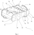
- the mounting unit 1 illustrated in Fig. 1 comprises a hot low-pressure air channel 2, a cool low-pressure air channel 3, a hot high-pressure air channel 4, and a cool high-pressure air channel 5, all of which have a tubular cross-sectional shape, and extend longitudinally and parallel with each other.
- the air channels 2, 3, 4, 5 are arranged parallel with respect to each other and one next another in a first lateral direction, transverse to the longitudinal.
- the mounting unit further comprises a mounting base 6 for attaching at least a low-pressure turbocharger and a high-pressure turbocharger to the mounting unit.
- the mounting base 6 is arranged on a side of the mounting unit 1 in a second lateral direction, transverse to the longitudinal and the first lateral directions.
- the mounting base 6, the hot low-pressure air channel 2, cool low-pressure air channel 3, hot high-pressure air channel 4 and the cool high-pressure air channel 5 are provided as a single, rigid structure.
- the air channels 2, 3, 4, 5 are arranged parallel with respect to each other and one next to another in a first lateral direction, transverse to the longitudinal.
- the mounting base 6 is arranged on a side of the mounting unit 1 in a second lateral direction, transverse to the longitudinal and the first lateral directions.
- the hot low-pressure air channel 2 has a low-pressure turbocharger compressor outlet port 2a provided at the mounting base 6.
- the hot low-pressure air channel 2 also has two opposing longitudinal ends 2c, 2d each with a flanged annular end surface, either of which may serve as a low-pressure heat exchanger inlet port 2b.
- the cool low-pressure air channel 3 has two opposing longitudinal ends 3c, 3d each with a flanged annular end surface, either or which may serve as a low-pressure heat-exchanger outlet port 3a.
- the cool low-pressure air channel 3 also has a high-pressure turbocharger compressor inlet port 3b provided on the same side of the mounting unit 1 as the mounting base 6, separate therefrom.
- the hot high-pressure air channel 4 has a high-pressure turbocharger compressor outlet port 4a provided at the mounting base 6.
- the hot high-pressure air channel 4 also has two opposing longitudinal ends 4c, 4d, each with a flanged annular end surface, either of which may serve as a high-pressure heat exchanger inlet port 4b
- the cool high-pressure air channel 5 has two opposing longitudinal ends 5c, 5d, each with a flanged annular end surface, either or which may serve as a high-pressure heat-exchanger outlet port 5a.
- the cool high-pressure air channel 5 also has a charge air feed port 5b, extending in the first lateral direction from the associated air channel 5 at an inclination with respect to said first lateral direction.
- the high-pressure cool air channel 5 is arranged laterally outermost (i.e. in the first lateral direction) with respect to the remaining air channels 2, 3, 4, whereas the low-pressure hot air channel 2 and the high-pressure hot air channel 4 are arranged immediately adjacent to each other.
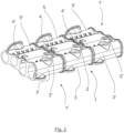
- Fig. 2 illustrates a schematic representation of multiple mounting units of Fig. 1 coupled to each other, as seen as a perspective view from a side of having a mounting base, showing the charge air feed port 5b.
- the arrangement has a mounting unit 1, coupled to identical mounting units 1' at each longitudinal end thereof.
- the hot low-pressure air channel 2 is coupled at both of its longitudinal ends 2c, 2d to corresponding longitudinal ends 2c', 2d' of corresponding low-pressure air channels 2', so as to form a continuous longitudinal hot low-pressure air channel 2', 2, 2'.
- the cool low-pressure air channel 3 is coupled at both of its longitudinal ends 3c, 3d to corresponding longitudinal ends 3c', 3d' of corresponding cool low-pressure air channels 3', so as to form a continuous longitudinal hot low-pressure air channel 3', 3, 3'.
- the hot high-pressure air channel 4 is coupled at both of its longitudinal ends 4c, 4d to corresponding longitudinal ends 4c', 4d' of corresponding hot high-pressure air channels 4', so as to form a continuous longitudinal hot high-pressure air channel 4', 4, 4'.
- the cool high-pressure air channel 5 is coupled at both of its longitudinal ends 5c, 5d to corresponding longitudinal ends 5c', 5d' of corresponding cool high-pressure air channels 5', so as to form a continuous longitudinal cool high-pressure air channel 5', 5, 5'.
- Fig. 3 shows the arrangement of Fig. 2 as seen from a side of the mounting units 1', 1, 1' opposite to the mounting bases 6', 6, 6.
- Fig. 3 illustrates the cool low-pressure air channels 3', 3, 3' also being equipped with additional an low-pressure heat exchanger outlet ports 3e', 3e, 3e' provided on a side of the respective mounting units 1', 1, 1' opposite to the mounting bases 6', 6, 6'.
- the cool high-pressure air channels 5', 5, 5' are equipped additional high-pressure heat exchanger outlet ports 5e', 5e, 5e'. It should be noted that such additional ports may also be provided on single mounting units 1, even without being attached to each other.
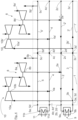
- Fig. 4 illustrates a schematic diagram of a turbocharger arrangement according to an embodiment of the present disclosure. Particularly, it shows how the hot low-pressure air channels 2, 2' of the first mounting unit 1 and the second mounting unit 1' are coupled to each other at their corresponding longitudinal ends 2c, 2d' to form a uniform air channel.
- the cool low-pressure air channels 3, 3' are coupled at their corresponding longitudinal ends 3c, 3d'
- the hot high-pressure channels 4 4' are coupled by their corresponding longitudinal lends 4c, 4d'
- the cool low-pressure channels 5, 5' are coupled to each other at their corresponding longitudinal lends 5c, 5d'.
- the compressor outlet 8b of the first low-pressure turbocharger 8 and the compressor outlet 8b' of the second low-pressure turbocharger 8' are both coupled to the uniform hot low-pressure air channel 2, 2' by the low-pressure turbocharger compressor outlet port 2a of the first mounting unit 1 and the low-pressure turbocharger compressor outlet port 2a' of the first mounting unit 1'. That is, both the first and second low-pressure turbochargers feed the uniform hot low-pressure air channel 2, 2', which is then coupled to the low-pressure heat exchanger inlet 9a of a common low-pressure heat exchanger 9 at the low-pressure heat exchanger inlet port 2b, provided at an longitudinal end 2d (being opposite to the longitudinal end 2c, at which the second mounting unit 1' is coupled).
- the low-pressure heat exchanger outlet 9b of the common low-pressure heat exchanger 9 is coupled to the uniform cool low-pressure air channel 3, 3', formed by the respective air channels 3, 3' of the first and second mounting units 1, 1', at the low-pressure heat exchanger outlet port 3as, formed at a longitudinal end 3d (being opposite to the longitudinal end 3c, at which the second mounting unit 1' is coupled).
- the uniform cool low-pressure air channel 3, 3' is coupled to the compressor inlets 10a, 10a' of both the first high-pressure turbocharger 10 and the second high pressure turbocharger 10' at the high-pressure turbocharger inlet ports 3b, 3b' of the first and second mounting units 1, 1', respectively.
- the compressor outlets 10b and 10b' of the high-pressure turbocharger are coupled to the uniform hot high-pressure air channel 4, 4' at the high-pressure turbocharger outlet ports 4a, 4a', thereof. Furthermore, the inlet 11a of the common high-pressure heat exchanger 11 is couple to the uniform hot high-pressure air channel 4, 4' at the high-pressure heat exchanger inlet port 4b formed at a longitudinal end 4d (being opposite to the longitudinal end 4c, at which the second mounting unit 1' is coupled).
- the high-pressure heat exchanger outlet 11b of the common high-pressure heat exchanger 11 is coupled to the uniform cool high-pressure air channel 5, 5' at the high-pressure heat exchanger outlet port 5a, formed at a longitudinal end 5d (being opposite to the longitudinal end 5c, at which the second mounting unit 1' is coupled).
- the charge air feed port 5b of the high-pressure air channel 5, 5' may then be further coupled to a charge air inlet of an associated engine.
Landscapes
- Engineering & Computer Science (AREA)
- Chemical & Material Sciences (AREA)
- Combustion & Propulsion (AREA)
- Mechanical Engineering (AREA)
- General Engineering & Computer Science (AREA)
- Manufacturing & Machinery (AREA)
- Physics & Mathematics (AREA)
- Thermal Sciences (AREA)
- Supercharger (AREA)
Claims (11)
- Montageeinheit (1) für eine Turbolader-Anordnung einer Hubkolben-Brennkraftmaschine, umfassendeinen längs verlaufenden Niederdruck-Heißluftkanal (2) mit:- einer Niederdruckturboladerverdichter-Auslassöffnung (2a) zum Bereitstellen einer Fluidverbindung zwischen einem Niederdruckturboladerverdichter-Auslass und dem Niederdruck-Heißluftkanal (2), und- einer Niederdruckwärmetauscher-Einlassöffnung (2b) zum Bereitstellen einer Fluidverbindung zwischen dem Niederdruck-Heißluftkanal (2) und einem Niederdruckwärmetauscher-Einlass;einen längs verlaufenden Niederdruck-Kaltluftkanal (3) mit:- einer Niederdruckwärmetauscher-Auslassöffnung (3a) zum Bereitstellen einer Fluidverbindung zwischen einem Niederdruckwärmetauscher-Auslass und dem Niederdruck-Kaltluftkanal (3), und- einer Hochdruckturboladerverdichter-Einlassöffnung (3b) zum Bereitstellen einer Fluidverbindung zwischen dem Niederdruck-Kaltluftkanal (3) und einem Hochdruckturboladerverdichter-Einlass;einen längs verlaufenden Hochdruck-Heißluftkanal (4) mit:- einer Hochdruckturboladerverdichter-Auslassöffnung (4a) zum Bereitstellen einer Fluidverbindung zwischen einem Hochdruckturboladerverdichter-Auslass und dem Hochdruck-Heißluftkanal (4), und- einer Hochdruckwärmetauscher-Einlassöffnung (4b) zum Bereitstellen einer Fluidverbindung zwischen dem Hochdruck-Heißluftkanal (4) und einem Hochdruckwärmetauscher-Einlass; undeinen längs verlaufenden Hochdruck-Kaltluftkanal (5) mit:- einer Hochdruckwärmetauscher-Auslassöffnung (5a) zum Bereitstellen einer Fluidverbindung zwischen einem Hochdruckwärmetauscher-Auslass und dem Hochdruck-Kaltluftkanal (5), und- einer Ladeluftzufuhröffnung (5b) zum Bereitstellen einer Fluidverbindung zwischen dem Hochdruck-Kaltluftkanal (5) und einem Ladelufteinlass einer zugehörigen Brennkraftmaschine,wobei die Montageeinheit (1) ferner einen Montagesockel (6) umfasst, um mindestens einen Niederdruckturbolader und einen Hochdruckturbolader an der Montageeinheit (1) zu befestigen,wobei der Montagesockel (6), der Niederdruck-Heißluftkanal (2), der Niederdruck-Kaltluftkanal (3), der Hochdruck-Heißluftkanal (4) und der Hochdruck-Kaltluftkanal (5) als eine einzige, starre Struktur vorgesehen sind,wobei die Luftkanäle (2, 3, 4, 5) parallel zueinander und nebeneinander in einer ersten Seitenrichtung, quer zur Längsrichtung, angeordnet sind,wobei der Montagesockel (6) auf einer Seite der Montageeinheit (1) in einer zweiten Seitenrichtung, quer zur Längs- und ersten Seitenrichtung, angeordnet ist, undwobei mindestens die Niederdruckturboladerverdichter-Auslassöffnung (2a) und die Hochdruckturboladerverdichter-Auslassöffnung (4a) am Montagesockel (6) angeordnet sind,gekennzeichnet dadurch, dass die Montageeinheit (1) mit einer identischen, zweiten Montageeinheit (1') direkt koppelbar ist, so dass, wenn gekoppelt, eine Fluidverbindung zwischen entsprechenden Luftkanälen (2, 2'; 3, 3'; 4,4'; 5, 5') der Montageeinheit (1) und der zweiten Montageeinheit (1') erzielt wird, wobei die Luftkanäle (2, 3, 4, 5) parallel zueinander angeordnet sind, undwobei mindestens ein, bevorzugt beide Längsenden (2c, 2d, 3c, 3d, 4c, 4d, 5c, 5d) der Luftkanäle (2, 3, 4, 5) so ausgelegt sind, dass sie mit einem Längsende (2c' 2d', 3c' 3d', 4c' 4d', 5c' 5d') eines entsprechenden Luftkanals (2', 3', 4', 5') einer identischen zweiten Montageeinheit (1') direkt koppelbar sind, so dass die entsprechenden Luftkanäle (2; 2', 3; 3', 4; 4', 5; 5') der Montageeinheit (1) und der zweiten Montageeinheit (1'), wenn gekoppelt, durchgehende längsverlaufende Luftkanäle bilden.
- Montageeinheit nach Anspruch 1, gekennzeichnet dadurch, dass mindestens die Niederdruckturboladerverdichter-Auslassöffnung (2a), die Hochdruckturboladerverdichter-Einlassöffnung (3b) und die Hochdruckturboladerverdichter-Auslassöffnung (4a) in Bezug auf die Luftkanäle (2, 3, 4, 5) auf einer gleichen Seite der Montageeinheit angeordnet sind.
- Montageeinheit (1) nach Anspruch 1 oder 2, gekennzeichnet dadurch, dass eine oder mehrere, bevorzugt sämtliche, der Niederdruckwärmetauscher-Einlassöffnung (2b), Niederdruckwärmetauscher-Auslassöffnung (3a), Hochdruckwärmetauscher-Einlassöffnung (4b) und Hochdruckwärmetauscher-Auslassöffnung (5a) an einem Längsende (2c, 2d, 3c, 3d, 4c, 4d, 5c, 5d) ihres zugehörigen Luftkanals (2, 3, 4, 5) angeordnet sind.
- Montageeinheit (1) nach Anspruch 3, gekennzeichnet dadurch, dass, eine oder mehrere, bevorzugt sämtliche:- eine zusätzliche Niederdruckwärmetauscher-Einlassöffnung zum Bereitstellen einer Fluidverbindung zwischen dem Niederdruck-Heißluftkanal (2) und einem Niederdruckwärmetauscher-Einlass;- eine zusätzliche Niederdruckwärmetauscher-Auslassöffnung (3e) zum Bereitstellen einer Fluidverbindung zwischen einem Niederdruckwärmetauscher-Auslass und dem Niederdruck-Kaltluftkanal (3);- eine zusätzliche Hochdruckwärmetauscher-Einlassöffnung (4e) zum Bereitstellen einer Fluidverbindung zwischen dem Hochdruck-Heißluftkanal (4) und einem Hochdruckwärmetauscher-Einlass, und- eine zusätzliche Hochdruckwärmetauscher-Auslassöffnung (5e) zum Bereitstellen einer Fluidverbindung zwischen einem Hochdruckwärmetauscher-Auslass und dem Hochdruck-Kaltluftkanal (5),in Bezug auf die Luftkanäle in der zweiten Seitenrichtung an einer dem Montagesockel (6) entgegengesetzten Seite der Montageeinheit angeordnet sind.
- Montageeinheit nach einem der vorhergehenden Ansprüche 1 bis 4, gekennzeichnet dadurch, dass der Niederdruck-Heißluftkanal (2) und der Niederdruck-Kaltluftkanal (3) unmittelbar angrenzend zueinander angeordnet sind, während der Hochdruck-Heißluftkanal (4) und der Hochdruck-Kaltluftkanal (5) unmittelbar angrenzend zueinander angeordnet sind.
- Montageeinheit nach einem der vorhergehenden Ansprüche 1 bis 5, gekennzeichnet dadurch, dass der Niederdruck-Heißluftkanal (2) und der Hochdruck-Heißluftkanal (4) unmittelbar angrenzend zueinander angeordnet sind.
- Montageeinheit (1) nach einem der vorhergehenden Ansprüche 1 bis 6, gekennzeichnet dadurch, dass der Hochdruck-Kaltluftkanal (5) in Bezug auf die übrigen Luftkanäle (2, 3, 4) seitlich ganz außen angeordnet ist.
- Turbolader-Anordnung (7) einer Hubkolben-Brennkraftmaschine, gekennzeichnet dadurch, dass sie umfassteine erste Montageeinheit (1) nach einem der vorhergehenden Ansprüche 1 bis 7;einen ersten Niederdruckturbolader (8) mit:- einem Verdichtereinlass (8a), der mit einer Luftversorgung koppelbar ist, und- einem Verdichterauslass (8b), der mit der Niederdruckturboladerverdichter-Auslassöffnung (2a) der ersten Montageeinheit (1) direkt gekoppelt ist, wobei der erste Niederdruckturbolader (8) auf die erste Montageeinheit (1) an deren Montagesockel (6) montiert wird;einen ersten Niederdruckwärmetauscher (9) mit:- einem Einlass (9a), der mit der Niederdruckwärmetauscher-Einlassöffnung (2b) der ersten Montageeinheit (1) gekoppelt ist, und- einem Auslass (9b), der mit der Niederdruckwärmetauscher-Auslassöffnung (3a) der ersten Montageeinheit gekoppelt ist, wobei der erste Niederdruckwärmetauscher (9) dazu ausgelegt ist, einen Niederdruckluftstrom zwischen seinem Einlass (9a) und Auslass (9b) zu kühlen;einen ersten Hochdruckturbolader (10) mit:- einem Verdichtereinlass (10a), der mit der Hochdruckturboladerverdichter-Einlassöffnung (3b) der ersten Montageeinheit (1) gekoppelt ist, und- einem Verdichterauslass (10b), der mit der Hochdruckturboladerverdichter-Auslassöffnung (4a) der ersten Montageeinheit (1) direkt gekoppelt ist, wobei der erste Hochdruckturbolader (10) auf die erste Montageeinheit (1) an deren Montagesockel (6) montiert wird, undeinen ersten Hochdruckwärmetauscher (11) mit:- einem Einlass (11a), der mit der Hochdruckwärmetauscher-Einlassöffnung (4b) der ersten Montageeinheit (1) gekoppelt ist, und- einem Auslass (11b), der mit der Hochdruckwärmetauscher-Auslassöffnung (5a) der ersten Montageeinheit (1) gekoppelt ist, wobei der erste Hochdruckwärmetauscher (11) dazu ausgelegt ist, einen Hochdruckluftstrom zwischen seinem Einlass (11a) und Auslass (11b) zu kühlen.
- Turbolader-Anordnung nach Anspruch 8, gekennzeichnet dadurch, dass die erste Montageeinheit (1) eine Montageeinheit nach einem der vorhergehenden Ansprüche 3 bis 7 ist,
wobei die Turbolader-Anordnung ferner umfasst:eine zweite Montageeinheit (1'), bei der es sich auch um eine Montageeinheit nach einem der vorhergehenden Ansprüche 3 bis 7 handelt, die mit der ersten Montageeinheit (1) über die Längsenden (2c; 2c', 2d; 2d', 3c; 3c', 3d; 3d', 4c; 4c', 4d; 4d', 5c; 5c', 5d; 4d') der entsprechenden Luftkanäle (2; 2', 3, 3'; 4,4'; 5, 5') der ersten Montageeinheit beziehungsweise zweiten Montageeinheit (1') gekoppelt ist, so dass die entsprechenden Luftkanäle (2; 2', 3, 3'; 4,4'; 5, 5') der ersten Montageeinheit (1) und der zweiten Montageeinheit (1') durchgehende längsverlaufende Luftkanäle bilden;einen zweiten Niederdruckturbolader (8') mit:- einem Verdichtereinlass (8a'), der mit einer Luftversorgung koppelbar ist, und- einem Verdichterauslass (8b'), der mit der Niederdruckturboladerverdichter-Auslassöffnung (2a') der zweiten Montageeinheit (1') direkt gekoppelt ist, wobei der zweite Niederdruckturbolader (8') auf die zweite Montageeinheit (1') an deren Montagesockel (6') montiert wird; undeinen zweiten Hochdruckturbolader (10') mit:- einem Verdichtereinlass (10a'), der mit der Hochdruckturboladerverdichter-Einlassöffnung (3b') der zweiten Montageeinheit (1') gekoppelt ist, und- einem Verdichterauslass (10b'), der mit der Hochdruckturboladerverdichter-Auslassöffnung (4a') der zweiten Montageeinheit (1') direkt gekoppelt ist, wobei der zweite Hochdruckturbolader (10') auf die zweite Montageeinheit (1') an deren Montagesockel (6') montiert wird. - Turbolader-Anordnung nach Anspruch 9, gekennzeichnet dadurch, dass die Turbolader-Anordnung ferner umfasst:einen zweiten Niederdruckwärmetauscher (9') mit:- einem Einlass (9a'), der mit der Niederdruckwärmetauscher-Einlassöffnung (2b') der zweiten Montageeinheit (1') gekoppelt ist, und- einem Auslass (9b'), der mit der Niederdruckwärmetauscher-Auslassöffnung (3a') der zweiten Montageeinheit (1') gekoppelt ist, wobei der zweite Niederdruckwärmetauscher (9') dazu ausgelegt ist, einen Niederdruckluftstrom zwischen seinem Einlass (9a') und Auslass (9b') zu kühlen, undeinen zweiten Hochdruckwärmetauscher (11) mit:- einem Einlass (11a'), der mit der Hochdruckwärmetauscher-Einlassöffnung (4b') der zweiten Montageeinheit (1') gekoppelt ist, und- einem Auslass (11b'), der mit der Hochdruckwärmetauscher-Auslassöffnung (5b') der zweiten Montageeinheit (1') gekoppelt ist, wobei der zweite Hochdruckwärmetauscher (11') dazu ausgelegt ist, einen Hochdruckluftstrom zwischen seinem Einlass (11a') und Auslass (11b') zu kühlen.
- Hubkolben-Brennkraftmaschine, gekennzeichnet dadurch, dass sie die Turbolader-Anordnung nach einem der vorhergehenden Ansprüche 8 bis 10 umfasst,
wobei eine Ladeluftzufuhröffnung (5b, 5b') der ersten Montageeinheit (1) und/oder der zweiten Montageeinheit (1') mit einem Ladelufteinlass der Brennkraftmaschine gekoppelt ist.
Applications Claiming Priority (1)
| Application Number | Priority Date | Filing Date | Title |
|---|---|---|---|
| PCT/FI2020/050734 WO2022096770A1 (en) | 2020-11-06 | 2020-11-06 | A mounting unit for a turbocharger arrangement of a reciprocating internal combustion engine, a turbocharger arrangement and reciprocating internal combustion engine |
Publications (2)
| Publication Number | Publication Date |
|---|---|
| EP4240948A1 EP4240948A1 (de) | 2023-09-13 |
| EP4240948B1 true EP4240948B1 (de) | 2024-10-09 |
Family
ID=73452229
Family Applications (1)
| Application Number | Title | Priority Date | Filing Date |
|---|---|---|---|
| EP20807820.4A Active EP4240948B1 (de) | 2020-11-06 | 2020-11-06 | Montageeinheit für eine turboladeranordnung eines hubkolbenverbrennungsmotors, turboladeranordnung und hubkolbenverbrennungsmotor |
Country Status (5)
| Country | Link |
|---|---|
| EP (1) | EP4240948B1 (de) |
| JP (1) | JP7697171B2 (de) |
| KR (1) | KR102781631B1 (de) |
| CN (1) | CN116490680B (de) |
| WO (1) | WO2022096770A1 (de) |
Family Cites Families (9)
| Publication number | Priority date | Publication date | Assignee | Title |
|---|---|---|---|---|
| JPH0610776A (ja) * | 1992-06-26 | 1994-01-18 | Honda Motor Co Ltd | 排ガス再循環装置およびその製造法 |
| AT501798B1 (de) * | 2005-04-25 | 2006-11-15 | Man Nutzfahrzeuge Oesterreich | Aufgeladene brennkraftmaschine |
| FR2886340B1 (fr) * | 2005-05-31 | 2010-11-12 | Valeo Systemes Thermiques | Refroidisseur d'air d'admission pour un moteur thermique turbocompresse a deux etages de suralimentation et circuit d'air correspondant |
| FI122963B (fi) * | 2008-06-03 | 2012-09-14 | Waertsilae Finland Oy | Mäntämoottorin alusta |
| FI122882B (fi) | 2008-06-03 | 2012-08-15 | Waertsilae Finland Oy | Mäntämoottori |
| JP2010281308A (ja) | 2009-06-08 | 2010-12-16 | Toyota Motor Corp | 過給装置及びこれを備える内燃機関 |
| DE102010041066B4 (de) * | 2010-09-20 | 2012-09-27 | Mtu Friedrichshafen Gmbh | Trägergehäuse und Brennkraftmaschine |
| DE102012203701B4 (de) | 2012-03-08 | 2024-09-05 | Man Energy Solutions Se | Abgasturboladermodul und damit ausgerüstete Brennkraftmaschine |
| GB2576882B (en) * | 2018-09-04 | 2021-06-16 | Caterpillar Motoren Gmbh & Co | Two-staged turbocharger |
-
2020
- 2020-11-06 KR KR1020237018952A patent/KR102781631B1/ko active Active
- 2020-11-06 JP JP2023526857A patent/JP7697171B2/ja active Active
- 2020-11-06 EP EP20807820.4A patent/EP4240948B1/de active Active
- 2020-11-06 CN CN202080106803.9A patent/CN116490680B/zh active Active
- 2020-11-06 WO PCT/FI2020/050734 patent/WO2022096770A1/en not_active Ceased
Also Published As
| Publication number | Publication date |
|---|---|
| CN116490680B (zh) | 2025-08-15 |
| JP2023548521A (ja) | 2023-11-17 |
| KR20230097182A (ko) | 2023-06-30 |
| KR102781631B1 (ko) | 2025-03-13 |
| EP4240948A1 (de) | 2023-09-13 |
| CN116490680A (zh) | 2023-07-25 |
| WO2022096770A1 (en) | 2022-05-12 |
| JP7697171B2 (ja) | 2025-06-30 |
Similar Documents
| Publication | Publication Date | Title |
|---|---|---|
| US5810071A (en) | Heat exchanger | |
| US20090084364A1 (en) | Intake Air Cooler For Dual-State Turbocharging Turbocompressed Heat Engine And Corresponding Air Circuit | |
| US4702079A (en) | Air-cooled type intercooler for a supercharged internal combustion engine | |
| US20100083920A1 (en) | Cylinder head for an internal combustion engine | |
| US20100071639A1 (en) | Charge-air cooling device, system for turbocharging and/or charge-air cooling, method for charge-air cooling | |
| EP1429101A3 (de) | Wärmetauscher mit keilförmigen Rohren mit gleichmässiger Kühlmediumströmung | |
| US6966173B2 (en) | Heat transfer apparatus | |
| EP0167807B1 (de) | Verdichtungsanlage für Wärmekraftmaschinen | |
| EP1211463A3 (de) | Rippenplatte und Brennkammer mit der Rippenplatte | |
| US11384990B2 (en) | Prime surface heat exchanger with contoured separator members | |
| EP1788333A1 (de) | Luftkühler | |
| US6422020B1 (en) | Cast heat exchanger system for gas turbine | |
| EP4240948B1 (de) | Montageeinheit für eine turboladeranordnung eines hubkolbenverbrennungsmotors, turboladeranordnung und hubkolbenverbrennungsmotor | |
| EP2370680B1 (de) | Systemluftkühler zum kühlen von in einen suprageladenen verbrennungsmotor geleiteter luft | |
| US20100044022A1 (en) | Air-to-air cooling assembly | |
| EP0789808B1 (de) | Anordnung am einlasskrümmer einer brennkraftmaschine | |
| US20020002820A1 (en) | Gas turbine apparatus with heat exchanger | |
| EP1849989A1 (de) | Kanal zur Verbindung eines Verdichters und eines Zwischenkühlers | |
| CN110886627B (zh) | 一种组合发动机用一体化机匣 | |
| GB2451113A (en) | Corrugations of a heat exchanger matrix having first and second different amplitudes | |
| US20040079346A1 (en) | Engine air charge system with branch conduits | |
| WO2024089220A1 (en) | An integrated forced-induction and heat exchanger apparatus | |
| EP3847357B1 (de) | Ladeluftkühleinheit für zweistufiger turbolader | |
| US10934911B2 (en) | Heat shield system and method | |
| EP3671092B1 (de) | Ladeluftkühler |
Legal Events
| Date | Code | Title | Description |
|---|---|---|---|
| STAA | Information on the status of an ep patent application or granted ep patent |
Free format text: STATUS: UNKNOWN |
|
| STAA | Information on the status of an ep patent application or granted ep patent |
Free format text: STATUS: THE INTERNATIONAL PUBLICATION HAS BEEN MADE |
|
| PUAI | Public reference made under article 153(3) epc to a published international application that has entered the european phase |
Free format text: ORIGINAL CODE: 0009012 |
|
| STAA | Information on the status of an ep patent application or granted ep patent |
Free format text: STATUS: REQUEST FOR EXAMINATION WAS MADE |
|
| 17P | Request for examination filed |
Effective date: 20230523 |
|
| AK | Designated contracting states |
Kind code of ref document: A1 Designated state(s): AL AT BE BG CH CY CZ DE DK EE ES FI FR GB GR HR HU IE IS IT LI LT LU LV MC MK MT NL NO PL PT RO RS SE SI SK SM TR |
|
| DAV | Request for validation of the european patent (deleted) | ||
| DAX | Request for extension of the european patent (deleted) | ||
| GRAP | Despatch of communication of intention to grant a patent |
Free format text: ORIGINAL CODE: EPIDOSNIGR1 |
|
| STAA | Information on the status of an ep patent application or granted ep patent |
Free format text: STATUS: GRANT OF PATENT IS INTENDED |
|
| INTG | Intention to grant announced |
Effective date: 20240502 |
|
| GRAS | Grant fee paid |
Free format text: ORIGINAL CODE: EPIDOSNIGR3 |
|
| GRAA | (expected) grant |
Free format text: ORIGINAL CODE: 0009210 |
|
| STAA | Information on the status of an ep patent application or granted ep patent |
Free format text: STATUS: THE PATENT HAS BEEN GRANTED |
|
| RAP3 | Party data changed (applicant data changed or rights of an application transferred) |
Owner name: WAERTSILAE FINLAND OY |
|
| RIN1 | Information on inventor provided before grant (corrected) |
Inventor name: SANDBERG, JUHO Inventor name: RAIKIO, TERO |
|
| AK | Designated contracting states |
Kind code of ref document: B1 Designated state(s): AL AT BE BG CH CY CZ DE DK EE ES FI FR GB GR HR HU IE IS IT LI LT LU LV MC MK MT NL NO PL PT RO RS SE SI SK SM TR |
|
| REG | Reference to a national code |
Ref country code: CH Ref legal event code: EP |
|
| REG | Reference to a national code |
Ref country code: DE Ref legal event code: R096 Ref document number: 602020039215 Country of ref document: DE |
|
| REG | Reference to a national code |
Ref country code: IE Ref legal event code: FG4D |
|
| U01 | Request for unitary effect filed |
Effective date: 20241024 |
|
| U12 | Request for unitary effect withdrawn |
Effective date: 20241024 |
|
| REG | Reference to a national code |
Ref country code: LT Ref legal event code: MG9D |
|
| REG | Reference to a national code |
Ref country code: NL Ref legal event code: MP Effective date: 20241009 |
|
| REG | Reference to a national code |
Ref country code: AT Ref legal event code: MK05 Ref document number: 1730812 Country of ref document: AT Kind code of ref document: T Effective date: 20241009 |
|
| PG25 | Lapsed in a contracting state [announced via postgrant information from national office to epo] |
Ref country code: NL Free format text: LAPSE BECAUSE OF FAILURE TO SUBMIT A TRANSLATION OF THE DESCRIPTION OR TO PAY THE FEE WITHIN THE PRESCRIBED TIME-LIMIT Effective date: 20241009 |
|
| PG25 | Lapsed in a contracting state [announced via postgrant information from national office to epo] |
Ref country code: NL Free format text: LAPSE BECAUSE OF FAILURE TO SUBMIT A TRANSLATION OF THE DESCRIPTION OR TO PAY THE FEE WITHIN THE PRESCRIBED TIME-LIMIT Effective date: 20241009 |
|
| PG25 | Lapsed in a contracting state [announced via postgrant information from national office to epo] |
Ref country code: IS Free format text: LAPSE BECAUSE OF FAILURE TO SUBMIT A TRANSLATION OF THE DESCRIPTION OR TO PAY THE FEE WITHIN THE PRESCRIBED TIME-LIMIT Effective date: 20250209 Ref country code: HR Free format text: LAPSE BECAUSE OF FAILURE TO SUBMIT A TRANSLATION OF THE DESCRIPTION OR TO PAY THE FEE WITHIN THE PRESCRIBED TIME-LIMIT Effective date: 20241009 |
|
| PG25 | Lapsed in a contracting state [announced via postgrant information from national office to epo] |
Ref country code: FI Free format text: LAPSE BECAUSE OF FAILURE TO SUBMIT A TRANSLATION OF THE DESCRIPTION OR TO PAY THE FEE WITHIN THE PRESCRIBED TIME-LIMIT Effective date: 20241009 |
|
| PG25 | Lapsed in a contracting state [announced via postgrant information from national office to epo] |
Ref country code: BG Free format text: LAPSE BECAUSE OF FAILURE TO SUBMIT A TRANSLATION OF THE DESCRIPTION OR TO PAY THE FEE WITHIN THE PRESCRIBED TIME-LIMIT Effective date: 20241009 |
|
| PG25 | Lapsed in a contracting state [announced via postgrant information from national office to epo] |
Ref country code: ES Free format text: LAPSE BECAUSE OF FAILURE TO SUBMIT A TRANSLATION OF THE DESCRIPTION OR TO PAY THE FEE WITHIN THE PRESCRIBED TIME-LIMIT Effective date: 20241009 |
|
| PG25 | Lapsed in a contracting state [announced via postgrant information from national office to epo] |
Ref country code: NO Free format text: LAPSE BECAUSE OF FAILURE TO SUBMIT A TRANSLATION OF THE DESCRIPTION OR TO PAY THE FEE WITHIN THE PRESCRIBED TIME-LIMIT Effective date: 20250109 |
|
| PG25 | Lapsed in a contracting state [announced via postgrant information from national office to epo] |
Ref country code: GR Free format text: LAPSE BECAUSE OF FAILURE TO SUBMIT A TRANSLATION OF THE DESCRIPTION OR TO PAY THE FEE WITHIN THE PRESCRIBED TIME-LIMIT Effective date: 20250110 Ref country code: AT Free format text: LAPSE BECAUSE OF FAILURE TO SUBMIT A TRANSLATION OF THE DESCRIPTION OR TO PAY THE FEE WITHIN THE PRESCRIBED TIME-LIMIT Effective date: 20241009 |
|
| PG25 | Lapsed in a contracting state [announced via postgrant information from national office to epo] |
Ref country code: PL Free format text: LAPSE BECAUSE OF FAILURE TO SUBMIT A TRANSLATION OF THE DESCRIPTION OR TO PAY THE FEE WITHIN THE PRESCRIBED TIME-LIMIT Effective date: 20241009 |
|
| PG25 | Lapsed in a contracting state [announced via postgrant information from national office to epo] |
Ref country code: RS Free format text: LAPSE BECAUSE OF FAILURE TO SUBMIT A TRANSLATION OF THE DESCRIPTION OR TO PAY THE FEE WITHIN THE PRESCRIBED TIME-LIMIT Effective date: 20250109 |
|
| REG | Reference to a national code |
Ref country code: CH Ref legal event code: PL |
|
| PG25 | Lapsed in a contracting state [announced via postgrant information from national office to epo] |
Ref country code: SM Free format text: LAPSE BECAUSE OF FAILURE TO SUBMIT A TRANSLATION OF THE DESCRIPTION OR TO PAY THE FEE WITHIN THE PRESCRIBED TIME-LIMIT Effective date: 20241009 |
|
| PG25 | Lapsed in a contracting state [announced via postgrant information from national office to epo] |
Ref country code: MC Free format text: LAPSE BECAUSE OF FAILURE TO SUBMIT A TRANSLATION OF THE DESCRIPTION OR TO PAY THE FEE WITHIN THE PRESCRIBED TIME-LIMIT Effective date: 20241009 |
|
| PG25 | Lapsed in a contracting state [announced via postgrant information from national office to epo] |
Ref country code: DK Free format text: LAPSE BECAUSE OF FAILURE TO SUBMIT A TRANSLATION OF THE DESCRIPTION OR TO PAY THE FEE WITHIN THE PRESCRIBED TIME-LIMIT Effective date: 20241009 |
|
| REG | Reference to a national code |
Ref country code: DE Ref legal event code: R097 Ref document number: 602020039215 Country of ref document: DE |
|
| PG25 | Lapsed in a contracting state [announced via postgrant information from national office to epo] |
Ref country code: LU Free format text: LAPSE BECAUSE OF NON-PAYMENT OF DUE FEES Effective date: 20241106 |
|
| REG | Reference to a national code |
Ref country code: CH Ref legal event code: PL |
|
| PG25 | Lapsed in a contracting state [announced via postgrant information from national office to epo] |
Ref country code: PT Free format text: LAPSE BECAUSE OF FAILURE TO SUBMIT A TRANSLATION OF THE DESCRIPTION OR TO PAY THE FEE WITHIN THE PRESCRIBED TIME-LIMIT Effective date: 20250404 |
|
| PG25 | Lapsed in a contracting state [announced via postgrant information from national office to epo] |
Ref country code: EE Free format text: LAPSE BECAUSE OF FAILURE TO SUBMIT A TRANSLATION OF THE DESCRIPTION OR TO PAY THE FEE WITHIN THE PRESCRIBED TIME-LIMIT Effective date: 20241009 |
|
| PG25 | Lapsed in a contracting state [announced via postgrant information from national office to epo] |
Ref country code: CH Free format text: LAPSE BECAUSE OF NON-PAYMENT OF DUE FEES Effective date: 20241130 |
|
| PG25 | Lapsed in a contracting state [announced via postgrant information from national office to epo] |
Ref country code: RO Free format text: LAPSE BECAUSE OF FAILURE TO SUBMIT A TRANSLATION OF THE DESCRIPTION OR TO PAY THE FEE WITHIN THE PRESCRIBED TIME-LIMIT Effective date: 20241009 |
|
| PG25 | Lapsed in a contracting state [announced via postgrant information from national office to epo] |
Ref country code: SK Free format text: LAPSE BECAUSE OF FAILURE TO SUBMIT A TRANSLATION OF THE DESCRIPTION OR TO PAY THE FEE WITHIN THE PRESCRIBED TIME-LIMIT Effective date: 20241009 |
|
| PG25 | Lapsed in a contracting state [announced via postgrant information from national office to epo] |
Ref country code: CZ Free format text: LAPSE BECAUSE OF FAILURE TO SUBMIT A TRANSLATION OF THE DESCRIPTION OR TO PAY THE FEE WITHIN THE PRESCRIBED TIME-LIMIT Effective date: 20241009 |
|
| PG25 | Lapsed in a contracting state [announced via postgrant information from national office to epo] |
Ref country code: IT Free format text: LAPSE BECAUSE OF FAILURE TO SUBMIT A TRANSLATION OF THE DESCRIPTION OR TO PAY THE FEE WITHIN THE PRESCRIBED TIME-LIMIT Effective date: 20241009 |
|
| PLBE | No opposition filed within time limit |
Free format text: ORIGINAL CODE: 0009261 |
|
| STAA | Information on the status of an ep patent application or granted ep patent |
Free format text: STATUS: NO OPPOSITION FILED WITHIN TIME LIMIT |
|
| PG25 | Lapsed in a contracting state [announced via postgrant information from national office to epo] |
Ref country code: LV Free format text: LAPSE BECAUSE OF FAILURE TO SUBMIT A TRANSLATION OF THE DESCRIPTION OR TO PAY THE FEE WITHIN THE PRESCRIBED TIME-LIMIT Effective date: 20241009 |
|
| REG | Reference to a national code |
Ref country code: BE Ref legal event code: MM Effective date: 20241130 |
|
| PG25 | Lapsed in a contracting state [announced via postgrant information from national office to epo] |
Ref country code: SE Free format text: LAPSE BECAUSE OF FAILURE TO SUBMIT A TRANSLATION OF THE DESCRIPTION OR TO PAY THE FEE WITHIN THE PRESCRIBED TIME-LIMIT Effective date: 20241009 |
|
| 26N | No opposition filed |
Effective date: 20250710 |
|
| GBPC | Gb: european patent ceased through non-payment of renewal fee |
Effective date: 20250109 |
|
| PG25 | Lapsed in a contracting state [announced via postgrant information from national office to epo] |
Ref country code: BE Free format text: LAPSE BECAUSE OF NON-PAYMENT OF DUE FEES Effective date: 20241130 Ref country code: GB Free format text: LAPSE BECAUSE OF NON-PAYMENT OF DUE FEES Effective date: 20250109 |
|
| PG25 | Lapsed in a contracting state [announced via postgrant information from national office to epo] |
Ref country code: FR Free format text: LAPSE BECAUSE OF NON-PAYMENT OF DUE FEES Effective date: 20241209 |
|
| PG25 | Lapsed in a contracting state [announced via postgrant information from national office to epo] |
Ref country code: IE Free format text: LAPSE BECAUSE OF NON-PAYMENT OF DUE FEES Effective date: 20241106 |
|
| PGFP | Annual fee paid to national office [announced via postgrant information from national office to epo] |
Ref country code: DE Payment date: 20251119 Year of fee payment: 6 |
|
| PG25 | Lapsed in a contracting state [announced via postgrant information from national office to epo] |
Ref country code: HU Free format text: LAPSE BECAUSE OF FAILURE TO SUBMIT A TRANSLATION OF THE DESCRIPTION OR TO PAY THE FEE WITHIN THE PRESCRIBED TIME-LIMIT; INVALID AB INITIO Effective date: 20201106 |