EP4240502B1 - Schneefahrzeug - Google Patents
Schneefahrzeug Download PDFInfo
- Publication number
- EP4240502B1 EP4240502B1 EP21794397.6A EP21794397A EP4240502B1 EP 4240502 B1 EP4240502 B1 EP 4240502B1 EP 21794397 A EP21794397 A EP 21794397A EP 4240502 B1 EP4240502 B1 EP 4240502B1
- Authority
- EP
- European Patent Office
- Prior art keywords
- snow
- snow vehicle
- vehicle
- traction wheel
- runners
- Prior art date
- Legal status (The legal status is an assumption and is not a legal conclusion. Google has not performed a legal analysis and makes no representation as to the accuracy of the status listed.)
- Active
Links
Images


Classifications
-
- B—PERFORMING OPERATIONS; TRANSPORTING
- B62—LAND VEHICLES FOR TRAVELLING OTHERWISE THAN ON RAILS
- B62M—RIDER PROPULSION OF WHEELED VEHICLES OR SLEDGES; POWERED PROPULSION OF SLEDGES OR SINGLE-TRACK CYCLES; TRANSMISSIONS SPECIALLY ADAPTED FOR SUCH VEHICLES
- B62M27/00—Propulsion devices for sledges or the like
-
- A—HUMAN NECESSITIES
- A63—SPORTS; GAMES; AMUSEMENTS
- A63C—SKATES; SKIS; ROLLER SKATES; DESIGN OR LAYOUT OF COURTS, RINKS OR THE LIKE
- A63C5/00—Skis or snowboards
- A63C5/08—Skis or snowboards motor-driven
-
- B—PERFORMING OPERATIONS; TRANSPORTING
- B62—LAND VEHICLES FOR TRAVELLING OTHERWISE THAN ON RAILS
- B62B—HAND-PROPELLED VEHICLES, e.g. HAND CARTS OR PERAMBULATORS; SLEDGES
- B62B13/00—Sledges with runners
- B62B13/02—Sledges with runners characterised by arrangement of runners
- B62B13/06—Sledges with runners characterised by arrangement of runners arranged in two or more parallel lines
- B62B13/08—Sledges with runners characterised by arrangement of runners arranged in two or more parallel lines with steering devices
-
- B—PERFORMING OPERATIONS; TRANSPORTING
- B62—LAND VEHICLES FOR TRAVELLING OTHERWISE THAN ON RAILS
- B62B—HAND-PROPELLED VEHICLES, e.g. HAND CARTS OR PERAMBULATORS; SLEDGES
- B62B15/00—Other sledges; Ice boats or sailing sledges
- B62B15/008—Wheeled sledges
-
- B—PERFORMING OPERATIONS; TRANSPORTING
- B62—LAND VEHICLES FOR TRAVELLING OTHERWISE THAN ON RAILS
- B62B—HAND-PROPELLED VEHICLES, e.g. HAND CARTS OR PERAMBULATORS; SLEDGES
- B62B17/00—Accessories or details of sledges
-
- B—PERFORMING OPERATIONS; TRANSPORTING
- B62—LAND VEHICLES FOR TRAVELLING OTHERWISE THAN ON RAILS
- B62B—HAND-PROPELLED VEHICLES, e.g. HAND CARTS OR PERAMBULATORS; SLEDGES
- B62B17/00—Accessories or details of sledges
- B62B17/06—Superstructures; Attachments therefor
- B62B17/063—Seats or other supports specially adapted for the user
- B62B17/065—Seats or other supports specially adapted for the user the user being standing up
-
- B—PERFORMING OPERATIONS; TRANSPORTING
- B62—LAND VEHICLES FOR TRAVELLING OTHERWISE THAN ON RAILS
- B62J—CYCLE SADDLES OR SEATS; AUXILIARY DEVICES OR ACCESSORIES SPECIALLY ADAPTED TO CYCLES AND NOT OTHERWISE PROVIDED FOR, e.g. ARTICLE CARRIERS OR CYCLE PROTECTORS
- B62J1/00—Saddles or other seats for cycles; Arrangement thereof; Component parts
- B62J1/12—Box-shaped seats; Bench-type seats, e.g. dual or twin seats
-
- B—PERFORMING OPERATIONS; TRANSPORTING
- B62—LAND VEHICLES FOR TRAVELLING OTHERWISE THAN ON RAILS
- B62J—CYCLE SADDLES OR SEATS; AUXILIARY DEVICES OR ACCESSORIES SPECIALLY ADAPTED TO CYCLES AND NOT OTHERWISE PROVIDED FOR, e.g. ARTICLE CARRIERS OR CYCLE PROTECTORS
- B62J1/00—Saddles or other seats for cycles; Arrangement thereof; Component parts
- B62J1/14—Separate pillions
-
- B—PERFORMING OPERATIONS; TRANSPORTING
- B62—LAND VEHICLES FOR TRAVELLING OTHERWISE THAN ON RAILS
- B62J—CYCLE SADDLES OR SEATS; AUXILIARY DEVICES OR ACCESSORIES SPECIALLY ADAPTED TO CYCLES AND NOT OTHERWISE PROVIDED FOR, e.g. ARTICLE CARRIERS OR CYCLE PROTECTORS
- B62J7/00—Luggage carriers
- B62J7/02—Luggage carriers characterised by the arrangement thereof on cycles
- B62J7/06—Luggage carriers characterised by the arrangement thereof on cycles arranged above the front wheel, e.g. on the handlebars
-
- B—PERFORMING OPERATIONS; TRANSPORTING
- B62—LAND VEHICLES FOR TRAVELLING OTHERWISE THAN ON RAILS
- B62J—CYCLE SADDLES OR SEATS; AUXILIARY DEVICES OR ACCESSORIES SPECIALLY ADAPTED TO CYCLES AND NOT OTHERWISE PROVIDED FOR, e.g. ARTICLE CARRIERS OR CYCLE PROTECTORS
- B62J9/00—Containers specially adapted for cycles, e.g. panniers or saddle bags
- B62J9/20—Containers specially adapted for cycles, e.g. panniers or saddle bags attached to the cycle as accessories
- B62J9/21—Containers specially adapted for cycles, e.g. panniers or saddle bags attached to the cycle as accessories above or alongside the front wheel, e.g. on the handlebars
-
- B—PERFORMING OPERATIONS; TRANSPORTING
- B62—LAND VEHICLES FOR TRAVELLING OTHERWISE THAN ON RAILS
- B62J—CYCLE SADDLES OR SEATS; AUXILIARY DEVICES OR ACCESSORIES SPECIALLY ADAPTED TO CYCLES AND NOT OTHERWISE PROVIDED FOR, e.g. ARTICLE CARRIERS OR CYCLE PROTECTORS
- B62J9/00—Containers specially adapted for cycles, e.g. panniers or saddle bags
- B62J9/20—Containers specially adapted for cycles, e.g. panniers or saddle bags attached to the cycle as accessories
- B62J9/22—Containers specially adapted for cycles, e.g. panniers or saddle bags attached to the cycle as accessories between the main frame tubes, e.g. suspended from the top tube
-
- B—PERFORMING OPERATIONS; TRANSPORTING
- B62—LAND VEHICLES FOR TRAVELLING OTHERWISE THAN ON RAILS
- B62K—CYCLES; CYCLE FRAMES; CYCLE STEERING DEVICES; RIDER-OPERATED TERMINAL CONTROLS SPECIALLY ADAPTED FOR CYCLES; CYCLE AXLE SUSPENSIONS; CYCLE SIDE-CARS, FORECARS, OR THE LIKE
- B62K13/00—Cycles convertible to, or transformable into, other types of cycles or land vehicle
- B62K13/08—Frames
-
- B—PERFORMING OPERATIONS; TRANSPORTING
- B62—LAND VEHICLES FOR TRAVELLING OTHERWISE THAN ON RAILS
- B62K—CYCLES; CYCLE FRAMES; CYCLE STEERING DEVICES; RIDER-OPERATED TERMINAL CONTROLS SPECIALLY ADAPTED FOR CYCLES; CYCLE AXLE SUSPENSIONS; CYCLE SIDE-CARS, FORECARS, OR THE LIKE
- B62K15/00—Collapsible or foldable cycles
- B62K15/006—Collapsible or foldable cycles the frame being foldable
- B62K15/008—Collapsible or foldable cycles the frame being foldable foldable about 2 or more axes
-
- B—PERFORMING OPERATIONS; TRANSPORTING
- B62—LAND VEHICLES FOR TRAVELLING OTHERWISE THAN ON RAILS
- B62K—CYCLES; CYCLE FRAMES; CYCLE STEERING DEVICES; RIDER-OPERATED TERMINAL CONTROLS SPECIALLY ADAPTED FOR CYCLES; CYCLE AXLE SUSPENSIONS; CYCLE SIDE-CARS, FORECARS, OR THE LIKE
- B62K3/00—Bicycles
- B62K3/002—Bicycles without a seat, i.e. the rider operating the vehicle in a standing position, e.g. non-motorized scooters; non-motorized scooters with skis or runners
-
- B—PERFORMING OPERATIONS; TRANSPORTING
- B62—LAND VEHICLES FOR TRAVELLING OTHERWISE THAN ON RAILS
- B62K—CYCLES; CYCLE FRAMES; CYCLE STEERING DEVICES; RIDER-OPERATED TERMINAL CONTROLS SPECIALLY ADAPTED FOR CYCLES; CYCLE AXLE SUSPENSIONS; CYCLE SIDE-CARS, FORECARS, OR THE LIKE
- B62K5/00—Cycles with handlebars, equipped with three or more main road wheels
- B62K5/02—Tricycles
- B62K5/023—Tricycles specially adapted for disabled riders, e.g. personal mobility type vehicles with three wheels
- B62K5/025—Tricycles specially adapted for disabled riders, e.g. personal mobility type vehicles with three wheels power-driven
-
- B—PERFORMING OPERATIONS; TRANSPORTING
- B62—LAND VEHICLES FOR TRAVELLING OTHERWISE THAN ON RAILS
- B62K—CYCLES; CYCLE FRAMES; CYCLE STEERING DEVICES; RIDER-OPERATED TERMINAL CONTROLS SPECIALLY ADAPTED FOR CYCLES; CYCLE AXLE SUSPENSIONS; CYCLE SIDE-CARS, FORECARS, OR THE LIKE
- B62K5/00—Cycles with handlebars, equipped with three or more main road wheels
- B62K5/02—Tricycles
- B62K5/027—Motorcycles with three wheels
-
- B—PERFORMING OPERATIONS; TRANSPORTING
- B62—LAND VEHICLES FOR TRAVELLING OTHERWISE THAN ON RAILS
- B62M—RIDER PROPULSION OF WHEELED VEHICLES OR SLEDGES; POWERED PROPULSION OF SLEDGES OR SINGLE-TRACK CYCLES; TRANSMISSIONS SPECIALLY ADAPTED FOR SUCH VEHICLES
- B62M27/00—Propulsion devices for sledges or the like
- B62M27/02—Propulsion devices for sledges or the like power driven
-
- A—HUMAN NECESSITIES
- A63—SPORTS; GAMES; AMUSEMENTS
- A63C—SKATES; SKIS; ROLLER SKATES; DESIGN OR LAYOUT OF COURTS, RINKS OR THE LIKE
- A63C2203/00—Special features of skates, skis, roller-skates, snowboards and courts
- A63C2203/12—Electrically powered or heated
-
- B—PERFORMING OPERATIONS; TRANSPORTING
- B62—LAND VEHICLES FOR TRAVELLING OTHERWISE THAN ON RAILS
- B62K—CYCLES; CYCLE FRAMES; CYCLE STEERING DEVICES; RIDER-OPERATED TERMINAL CONTROLS SPECIALLY ADAPTED FOR CYCLES; CYCLE AXLE SUSPENSIONS; CYCLE SIDE-CARS, FORECARS, OR THE LIKE
- B62K2204/00—Adaptations for driving cycles by electric motor
-
- B—PERFORMING OPERATIONS; TRANSPORTING
- B62—LAND VEHICLES FOR TRAVELLING OTHERWISE THAN ON RAILS
- B62M—RIDER PROPULSION OF WHEELED VEHICLES OR SLEDGES; POWERED PROPULSION OF SLEDGES OR SINGLE-TRACK CYCLES; TRANSMISSIONS SPECIALLY ADAPTED FOR SUCH VEHICLES
- B62M27/00—Propulsion devices for sledges or the like
- B62M27/02—Propulsion devices for sledges or the like power driven
- B62M2027/022—Snow drive conversions for cycles with wheels
-
- B—PERFORMING OPERATIONS; TRANSPORTING
- B62—LAND VEHICLES FOR TRAVELLING OTHERWISE THAN ON RAILS
- B62M—RIDER PROPULSION OF WHEELED VEHICLES OR SLEDGES; POWERED PROPULSION OF SLEDGES OR SINGLE-TRACK CYCLES; TRANSMISSIONS SPECIALLY ADAPTED FOR SUCH VEHICLES
- B62M27/00—Propulsion devices for sledges or the like
- B62M27/02—Propulsion devices for sledges or the like power driven
- B62M2027/025—Snow mobiles characterised by the skis
Definitions
- Various embodiments relate to a snow vehicle.
- GB 2195298 B discloses a vehicle resembling a kicksled and employing a motor.
- US 4,087,106 discloses a three-point contact cambering vehicle with wheels, or alternatively with ice skates or snow skis.
- WO 2016/170364 A1 discloses a reconfigurable wheeled personal mobility device.
- various hobbyists also provide motorized kicksleds, but they are rather designed for motorsports and high speeds.
- US 4087106 discloses a snow vehicle according to the preamble of claim 1. A more sophisticated and safe snow vehicle is clearly desirable.
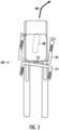
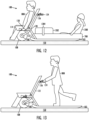
- FIG. 1 providing a side view
- FIG. 2 providing a top view.
- the snow vehicle 100 comprises a pair of runners 102, 104 configured to support the snow vehicle 100 travelling over snow and/or ice 150. As shown in FIG. 2 , the pair of runners 102, 104 are placed side by side, so that a driver of the snow vehicle 100 may stand on the pair of runners 102, 104, one foot on each.
- the pair of runners 102, 104 are implemented as a pair of skis dimensioned to glide the snow vehicle 100 over a compressed trail covered by the snow and/or the ice 150, and over a cared road covered by the snow and/or the ice 150.
- the compressed trail may be a snowmobile track or route, for example.
- the cared road includes pavements and is typically in public use and snow is ploughed as needed.
- the snow vehicle 100 may not be designed to operate in deep unbroken snow. Depending on the design and use case, the typical maximum snow depth may be 10-20 centimetres, for example.
- the pair of skis may be implemented with synthetic material, possibly augmented by suitable metallic structures.
- the pair of runners 102, 104 simultaneously combine the pair of skis with a pair of flexible metal runners placed at bottoms of the skis, which results in that the snow vehicle is mainly supported by the pair of skis while travelling over snow, and by the pair of flexible runners while travelling over ice.
- Each relatively low flexible metal runner may be embedded in the bottom of the ski so that it extends along the longitudinal axis of the ski.
- the bottom of the ski may be provided with a groove, which accommodates the low metal runner so that it protrudes partly to contact the ice, but also to protect the bottom of the ski (from debris, rocks, and cobblestones, for example) while driving in the summer with optional rear tyres 602 (described later).
- the low metal runners may be made of aluminium, for example, and they may be replaceable when beaten-up from use.
- the snow vehicle comprises an electric motor 106 and a traction wheel 108, powered by the electric motor 106, and configured to cause a propulsion (or traction) for the snow vehicle 100 while rolling in contact with the snow and/or the ice 150.
- the electric motor 106 is powered by one or more rechargeable batteries (not illustrated in FIG. 1 ).
- the one or more rechargeable batteries may be of a similar type as used in e-bikes.
- the one or more rechargeable batteries may be placed on a suitable place within a frame such as under a seat 114 or behind a backrest 116, for example.
- the frame of the snow vehicle is similar to a metallic frame used in a kicksled (or spark), but also other kind of structures employing also synthetic material may be designed depending on the use case.
- the frame comprises two supports 118, 120 for the pair of runners 102, 104.
- the supports 118, 120 may also be implemented as a single integrated structure, possibly also carrying the one or more batteries.
- the one or more supports 118, 120 are provided with one or more shock absorbers, such as with a telescopic suspension employing a spring (implemented with a steel or titanium spring, compressed air, or an elastomer) and a damper.
- the electric motor 106 may be a wheel hub motor incorporated into a hub of the traction wheel 108.
- the wheel hub motor 106 may be of a similar type and configuration as those used in e-bikes.
- the wheel hub motor 106 may contain the one or more batteries.
- the electric motor 106 may be a direct drive system, wherein the motor 106 directly drives the wheel 108, or the electric motor 106 may be a geared system, wherein the motor 106 drives the wheel 108 via a set of gears.
- the wheel hub motor 106 improves the stability of the snow vehicle 100 as the centre of gravity is relatively low (when compared to a separate motor placed above the traction wheel 108, for example).
- the frame of the snow vehicle 100 comprises one or more joints 138 configured so that the snow vehicle 100 is collapsible for storage and transport. Possible directions of folding are illustrated in FIG. 1 with arrows 140 and 142.
- the traction wheel 108 may be implemented as a pneumatic tyre (with a rim, and either a tubed or tubeless tyre), with a tyre size of 16, 18, 19, 20, 21 or 22 inches, for example.
- the traction wheel 108 is of the low pressure -type (possibly designed for low ground pressure such as in an ATV or fat-bike), and/or the traction wheel 108 is of the snow tyre -type, and/or the traction wheel 108 comprises studs.
- Snow tyres (or winter tyres) usually have a tread design with larger gaps than in traditional (summer) tyres. Some snow tyre have protruding metal or ceramic studs to increase traction on hard-packed snow or ice.
- the traction wheel 108 may be similar to that used in an all-terrain vehicle (ATV, also known as quad).
- ATV all-terrain vehicle
- the snow vehicle 100 may comprise a seat 114 positioned above the traction wheel 108 and configured to accommodate a person.
- the seat 114 may also include a backrest 116. Both may be manufactured from wood or synthetic material, for example.
- the advantage of positioning the seat 114 over the traction wheel 108 is that ground grip is improved if there is a person or goods on the seat 114.
- the snow vehicle 100 may comprise a steering arrangement comprising a steering axle 122 coupled with the traction wheel 108.
- the steering axle 122 may comprise structures similar to those of a bicycle comprising a steerer tube mounted within a frame tube and a fork configured to hold the traction wheel 108.
- the fork may contain a set of shock absorbers.
- the steering arrangement may comprise a handlebar-level steering bar 124 coupled with the steering axle 122 and configured and positioned to enable steering of the traction wheel 108 while a driver is standing on the pair or runners 102, 104.
- the steering arrangement may comprise a seat-level steering bar 128 coupled with the steering axle 122 and configured and positioned to enable steering of the traction wheel 108 while a driver is sitting on the seat 114.
- both steering bars 124, 128 may be similar to those used in a bicycle, wherein the handlebar is coupled to a stem coupled with the steerer tube.
- the handlebar-level steering bar 124 resembles a handlebar having a straight central section attached to the steering axle 122, with each end curving back towards the driver.
- the seat-level steering bar 128 resembles an under-seat handlebar of a recumbent.
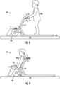
- FIG. 8 illustrates the driver 800 standing on the pair or runners 102, 104 and hanging onto the handlebar-level steering bar 124 to steer the traction wheel 108 via the steering axle 122.
- the pair of runners 102, 104 may extend behind the traction wheel 108, thereby enabling the driver 800 to select a best spot to stand on the pair of runners 102, 104.
- the pair of runners 102, 104 may thus each be configured to extend from a vicinity of the traction wheel 108 to a rear of the snow vehicle 100 to offer a continuous footrest platform for the driver 800. Even though the bottom of each ski 102, 104 may be horizontal, the top of each ski 102, 104 may be slant inwards to provide a more secure footrest platform for the driver 800.
- FIG. 9 illustrates the driver 800 sitting on the seat 114 and grabbing the seat-level steering bar 128 to steer the traction wheel 108 via the steering axle 122.
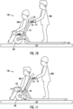
- FIG. 10 illustrates the driver 800 standing on the pair or runners 102, 104 and hanging onto the handlebar-level steering bar 124, while a passenger 1000 is sitting on the seat 114.
- the driver 800 sits on the seat 114 and grabs the seat-level steering bar 128, whereas the passenger 1000 is standing on the pair of runners 102, 104.
- both the driver 800 and the passenger 1000 may both grab the steering bar 124, 128 and also actually steer. This necessitates some co-ordination and communication, but may also help in a tight spot requiring careful steering.
- the traction wheel 108 is positioned in front of the pair of runners 102, 104.
- the wheel may be positioned between the front part of the pair of runners (like in a normal type of a kicksled), but the traction and steering effect may be improved by the in front -placing.
- the traction and steering is still improved (when compared to the situation wherein the traction wheel is positioned wholly between the runners).
- the steering arrangement comprises a first accelerator lever 126 coupled with the handlebar-level steering bar 124 and a second accelerator lever 130 coupled with the seat-level steering bar 128.
- the steering arrangement comprises a power switch 136 configured to enable the first accelerator lever 126 in a first switch position and the second accelerator lever 130 in a second switch position.
- the power switch 136 may operate with an ignition key or some other access control means to prohibit unauthorized use.
- the accelerator lever 126, 130 may be implemented as a thumb throttle.
- the driver 800 may choose which accelerator lever 126/130 to use: in the use case of FIG. 10 , the driver 800 enables the first accelerator lever 126, whereas in FIG. 11 , the driver 800 enables the second accelerator lever 130. In this way, the passenger 1000 cannot accelerate as his/her accelerator lever is not functional.
- the power switch 136 may additionally, or alternatively, be configured to operate in at least two power positions, wherein the first power position provides only a limited power from the electric motor 106 (or a limited maximum speed for the snow vehicle 100), and the second power position provides a full power from the electric motor 106 (or an unlimited maximum speed for the snow vehicle 100).
- an optional mechanical limiter may be provided for the power switch 136: when in use, the mechanical limiter only allows the first power position for the power switch 136, whereby an elderly person or a young person may safely drive the snow vehicle 100.
- forward-facing ends of the seat-level steering bar 128 comprise headlights 132, 134 configured to turn in unison with the steering axle 122.
- FIG. 3 also illustrates the principle of steering by turning the traction wheel 108, whereby the snow vehicle 100 advances into the direction of arrow 300.
- a clamp-mounted headlight (not illustrated) may be fixed to a frame tube, a steering bar 124, or to another suitable location in the front end of the snow vehicle 100.
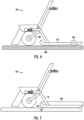
- FIG. 4 illustrates an embodiment, wherein the snow vehicle 100 comprises a footrest 112 configured and positioned so that it acts as a front ski in contact with an upper surface 500 of the snow 150 while the traction wheel 108 is partly buried deeper in the snow 150.
- the footrest 112 is coupled by a joint with a frame of the snow vehicle 100 so that the footrest 112 is configured to follow a topography of the upper surface 500 of the snow 150.
- FIG. 5 illustrates an embodiment, wherein the footrest 112 is configured to swivel into a position accommodating goods placed on the seat 114.
- the backrest 116 may be configured so that it may swivel to cover as a lid the extended compartment formed by the seat 114 and the footrest 112.
- the footrest 112 may be configured to swivel so that it covers as a lid the compartment formed by the seat 114.
- the snow vehicle 100 comprises at least two tyres 602 couplable with the pair of runners 102.
- the at least two tyres 602 are configured to, in a drive position, support the snow vehicle 100 travelling over a surface 600 having no snow and/or ice or having the snow and/or the ice covered with gravel.
- each tyre may be 602 attachable to the back end of each runner 102, 104.
- the tyres 602 may be of the solid type used in rollerblades, but they may also be pneumatic.
- Additional tyres may be placed in front of the runners 102, 104, although as shown in FIG 6 , the runners 102, 104 may be lifted off the ground surface 600 even with a pair of tyres 602.
- the at least two tyres 602 may be removably attachable. Another option is that the at least two tyres 602 are attached to the runners 102, 104 so that that may be positioned between the drive position and a storage position (wherein the at least two tyres 602 do not contact the ground beneath).
- the electric motor 106 comprises a disconnect mechanism 110 to disconnect the electric motor 106 from the traction wheel 108 enabling the traction wheel 108 to freewheel while the snow vehicle 100 is powered by the driver kicking the snow and/or the ice 150 by foot. Note that the freewheeling may also take placing while riding down a hill to save the one or more batteries.
- the electric motor 106 is configured to implement a braking functionality by hindering or stopping the rolling of the traction wheel 108. Such braking may also be regenerative, i.e., during the braking, the one or more batteries are recharged.
- the electric motor 106 is configured to rotate the traction wheel 108 in reverse to back up the snow vehicle 100.
- the pair of runners 102, 104 is configured to accommodate a toboggan 700 configured to transport one or more persons 1200 and/or goods 1202 (while the driver is sitting on the seat 114, or even standing on the pair of runners 102, 104).
- the toboggan 700 may be provided with fastening means 1204 to secure the goods 1202 during the ride.
- the toboggan 700 may be provided with seating arrangements for the passengers 1200.
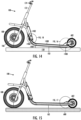
- FIG. 14 Let us next study FIG. 14, FIG. 15 , FIG. 16, FIG. 17 , FIG. 18 , FIG. 19, FIG. 20, and FIG. 21 , which illustrate various structural embodiments of the snow vehicle 100.
- the snow vehicle 100 is provided with the earlier explained steering arrangement comprising the steering axle 122 coupled with the traction wheel 108 and the handlebar-level steering bar 124 coupled with the steering axle 122 and configured and positioned to enable steering of the traction wheel 108 while the driver 800 is standing on the pair or runners 102, 104.
- the traction wheel 108 is positioned in front of the pair of runners 102, 104. Furthermore, the pair of runners 102, 104 are each configured to incline so that a front 1406 of the runner 102, 104 is higher than a rear 1408 of the runner 102, 104. The inclination is clearly seen in FIG. 14 : an angle 1404 is shown between a runner 102 and a straight surface of the snow and/or ice 150. As shown in the drawings, the pair of skis 102, 104 each have a ski tip in the front, but each may also have a ski tip in the rear (to enable easier backing up).
- the pair of skis 102, 104 may be implemented with synthetic material, possibly augmented by suitable metallic structures such as a part 1400 of the frame of the snow vehicle 100.
- the driver 800 is standing between the front 1406 of the runners 102, 104 and the rear 1408 of the runners 102, 104.
- the snow vehicle 100 touches the ground 150 with the traction wheel 108 and the rears 1408 of the runners 102, 104.
- This increases the stability of the snow vehicle 100, and also also minimizes the friction between the runners 102, 104 and the ground 150.
- the fronts 1406 of the runners 102, 104 glide over the snow 150, and the friction between the runners 102, 104 and the snow is again minimized (as the fronts 1406 of the runners 102, 104 glide over the snow instead of ploughing the snow).
- the snow vehicle 100 of FIG. 14 is also provided with the earlier explained at least two tyres 602 coupled with the pair of runners 102, 104.
- the tyres 602 may be switched between two positions.
- FIG. 15 illustrates the tyres 602 in a drive position, wherein the tyres 602 support the snow vehicle 100 travelling over a surface 600 having no snow and/or ice or having the snow and/or the ice covered with gravel.
- the tyres 602 may be height adjustable in the drive position.
- FIG. 14 illustrates the tyres 602 in a storage position, wherein the tyres 602 let the pair of runners 102, 104 to support the snow vehicle 100 travelling over the snow and/or ice 150.
- the tyres 602 may be swivelled or folded so that they do not support the weight of the snow vehicle 100 on the snow and/or ice 150 beneath (a slight contact with the snow and/or ice 150 may remain).
- FIG. 16 and FIG. 17 illustrate a detail of a mechanism enabling the tyres 602 to move between the storage position and the drive position, and also enabling the tyres 602 to be height adjustable in the drive position.
- the mechanism comprises an arm 1600 coupled with the frame 1400 at one end and to a hub of the tyre 602 at the other end with a fixing 1602.
- the arm 1600 may swivel from the storage position of FIG. 16 to the drive position of FIG. 17 .
- the arm 1600 may be provided with holes 1604, 1606.
- a support 1608 is fixedly coupled with the frame 1400 and provided with a protruding spring-loaded pin 2100 as shown in FIG. 21 .
- the driver may then adjust the height of each tyre 602 by guiding the spring-loaded pin 2100 to the hole 1604 or the hole 1606.
- the number of holes 1604, 1606 in our example is two, but more holes 1604, 1606 may be used to provide more precise height adjustment.
- FIG. 19 illustrates a collapsed snow vehicle 100, enabled by the earlier explained embodiment, wherein the frame of the snow vehicle 100 comprises one or more joints 138 configured so that the snow vehicle 100 is collapsible for storage and transport.
- FIG. 18 illustrates a detail of the drive ready snow vehicle 100
- FIG. 20 illustrates a collapsed snow vehicle 100, both enabled by the joint 138 connecting two parts 1400A, 1400B of the frame.
- FIG. 21 illustrates a detail of the mechanism 1600, 1608 enabling the tyres 602 to move between the storage position and the drive position. As shown, the arm 1600 is moved so that the collapsed snow vehicle 100 is as compact as possible.
- FIG. 22, FIG. 23 , FIG. 24, and FIG. 25 which illustrate various accessory embodiments for the snow vehicle 100.
- the snow vehicle 100 is of the type with the steering arrangement comprising the steering axle 122 coupled with the traction wheel 108, and the handlebar-level steering bar 124 coupled with the steering axle 122 and configured and positioned to enable steering of the traction wheel 108 while the driver 800 is standing on the pair or runners 102, 104.
- the snow vehicle 100 comprises an attachment mechanism 2200 configured to accommodate in front of the steering axle 122 an accessory.
- the accessory is a passenger seat 2300 accommodating a passenger 1000 (such as a child, a juvenile, or an adult, or even a pet such as a dog or a cat).
- the passenger seat may also be a multi-use bench (possibly containing a storage space).
- the accessory is a storage box 2400 (or a basket, for example).
- the accessory is a cool box 2500 or heat box 2500.
- the accessory may also be another type of usable extension to the functionalities of the snow vehicle 100 including, but not being limited to: a music player, a snow plough, a snowblower, one or more extra rechargeable batteries.
- the snow vehicle 100 comprises one or more rechargeable batteries 1402 configured to provide electric power to the electric motor 106, and a power output 2202 configured to provide electric power 2302, 2502 for the accessory 2300, 2500 from the one or or more rechargeable batteries 1402. Consequently, the power output 2202 may provide electric power 2302, 2502 to warm the seat 2300, to cool the cool box 2500, to heat the heat box 2500, to power the music player, to power the snowblower, etc.
- the accessory may include one or more extra rechargeable batteries
- the snow vehicle 100 may be provided with a power input to power the electric motor 106.
- the accessory requiring the electric power may also include one or more rechargeable batteries to provide extra or sole electric power for the accessory.
- the accessory may comprise additional parts, such as a lid 2504, a lock, fixing points for carrying load, hooks, a USB (Universal Serial Bus) interface, etc.
- the snow vehicle comprises a seat 2600 positioned between the pair of runners 102, 104 and configured to seat at least the driver 800.
- the seat 2600 may be long enough to seat the passenger 1200 (or even two passengers 1200, depending on the length of the seat 200 and the physical dimensions of the passengers 1200).
- the seat 2600 is dimensioned so that the driver 800, while seated, steers the snow vehicle 100 by turning the handlebar-level steering bar 124.
- the steering axle 122 may comprise a telescopic structure, which enables the driver 800 to adjust the height of the steering bar 124.
- the driver 800 and the passenger 1200 may keep their feet on the pair of runners 102, 104, or on the part 1400 of the frame.
- the seat 2600 may be fixedly placed on the snow vehicle 100, or alternatively, the seat 2600 may be removably attachable to the snow vehicle 100, enabling the driver 800 to switch between driving seated or standing.
- FIG. 27 illustrates that the seat 2600 may comprise a cover 2602, which may swivel to an open position, enabling loading of goods 2700 inside the seat 2602 for transportation.
- the seat 2600 may comprise a door on the side wall, and the door may be opened to load the goods 2700 into the seat 2600.
- the seat 2600 may be placed low so that the floor of the luggage space is at a slightly higher level then the pair of the runners 102, 104 (in order that the bottom of the seat 2600 does not abrade against the snow and/or ice 150).
- the luggage space within the seat 2600 may also be open at one or both ends (or even open at all four sides), thereby enabling loading and transportation of long objects (such as skis, etc.).
- the seat 2600 may also be a bench supported by legs (by four legs rising from the pair of runners 102, 104, for example), and, optionally, provided with a floor between the pair of runners 102, 104, thereby providing a flexible cargo space under the seat 2600.
- the snow vehicle 100 is capable of transporting the driver 800 in a wheelchair 2800.
- the wheelchair 2800 may be a manual self-propelled wheelchair or a powered wheelchair, but also another kind of mobility aid vehicle such as a mobility scooter.
- the structures of the snow vehicle 100 need to be designed to support and haul the extra weight of the mobility aid vehicle 2800.
- the snow vehicle 100 is configured to accommodate the mobility aid vehicle 2800.
- the mobility aid vehicle 2800 may be on top of the pair of runners 102, 104, or on the part 1400 of the frame.
- the snow vehicle 100 may be configured to dock the mobility aid vehicle 2800 to the snow vehicle 100.
- a mechanical connection (not illustrated) may be provided to fix the mobility aid vehicle 2800 immovably to the snow vehicle 100.
- a suitably formed ramp may be provided to enable the driver 800 on the mobility aid vehicle 2800 to board the snow vehicle 100. While riding the snow vehicle 100, the driver 800 may be seated on the mobility aid vehicle 2800 (on the wheelchair or the mobility scooter, for example).
- the steering axle 122 may comprise a telescopic structure, which enables the driver 800 to adjust the height of the steering bar 124.
- the steering axle 122 may also comprise a swivelling structure, which enables the driver 800 to adjust a distance to the steering bar 124.
- the described embodiments provide a safe and easy to use snow vehicle 100 for everyday use by ordinary people. As such, it may resemble an e-bike, possibly meeting some legislation requirements such as a top speed of 15 km/h, 25 km/h, or some other nationally mandated limit. Also, legal requirements set for the dimensions of a street-legal vehicle may be taken into account in the design. Naturally, as the described snow vehicle 100 defines a new type of vehicle, the legislation is still emerging.
Landscapes
- Engineering & Computer Science (AREA)
- Mechanical Engineering (AREA)
- Chemical & Material Sciences (AREA)
- Combustion & Propulsion (AREA)
- Transportation (AREA)
- Automatic Cycles, And Cycles In General (AREA)
- Motorcycle And Bicycle Frame (AREA)
- Cleaning Of Streets, Tracks, Or Beaches (AREA)
Claims (20)
- Schneefahrzeug (100), das Folgendes umfasst:ein Paar von Kufen (102, 104), die dazu ausgelegt sind, das Schneefahrzeug (100), das über Schnee und/oder Eis (150) fährt, zu stützen;einen Elektromotor (106); undein Traktionsrad (108), das vom Elektromotor (106) mit Energie versorgt wird und dazu ausgelegt ist, einen Antrieb für das Schneefahrzeug (100) zu bewirken, während es in Kontakt mit dem Schnee und/oder dem Eis (150) rollt,wobei das Traktionsrad (108) vor dem Paar von Kufen (102, 104) positioniert und dadurch gekennzeichnet ist, dass das Schneefahrzeug (100) vom Typ eines Tretschlittens ist.
- Schneefahrzeug nach Anspruch 1, wobei das Paar von Kufen (102, 104) jeweils dazu ausgelegt sind, sich derart zu neigen, dass eine Vorderseite (1406) der Kufe (102, 104) höher ist als eine Rückseite (1408) der Kufe (102, 104).
- Schneefahrzeug nach einem der vorhergehenden Ansprüche, wobei das Paar von Kufen (102, 104) ein Paar von Skiern umfassen, die dimensioniert sind, um das Schneefahrzeug (100) über eine komprimierte Spur, die von dem Schnee und/oder dem Eis (150) bedeckt ist, und über eine gepflegte Straße, die von dem Schnee und/oder dem Eis (150) bedeckt ist, zu gleiten.
- Schneefahrzeug nach einem der vorhergehenden Ansprüche, wobei das Schneefahrzeug (100) Folgendes umfasst:einen Sitz (114), der über dem Traktionsrad (108) positioniert und dazu ausgelegt ist, eine Person aufzunehmen; undeine Lenkanordnung, die eine Lenkachse (122), die an das Traktionsrad (108) gekoppelt ist, einen Lenkholm (124) auf Höhe einer Lenkstange, der an die Lenkachse (122) gekoppelt und dazu ausgelegt und positioniert ist, eine Lenkung des Traktionsrads (108) zu ermöglichen, während ein Fahrer auf dem Paar von Kufen (102, 104) steht, und einen Lenkholm (128) auf Sitzhöhe, der an die Lenkachse (122) gekoppelt und dazu ausgelegt und positioniert ist, eine Lenkung des Traktionsrads (108) zu ermöglichen, während ein Fahrer auf dem Sitz (114) sitzt.
- Schneefahrzeug nach Anspruch 4, wobei die Lenkanordnung einen ersten Gashebel (126), der an den Lenkholm (124) auf Höhe der Lenkstange gekoppelt ist, einen zweiten Gashebel (130), der an den Lenkholm (128) auf Sitzhöhe gekoppelt ist, und einen Energieschalter (136) umfasst, der dazu ausgelegt ist, den ersten Gashebel (126) in einer ersten Schaltposition und den zweiten Gashebel (130) in einer zweiten Schaltposition zu aktivieren.
- Schneefahrzeug nach Anspruch 4 oder 5, wobei die nach vorn weisenden Enden des Lenkholms (128) auf Sitzhöhe Scheinwerfer (132, 134) umfassen, die dazu ausgelegt sind, sich zusammen mit einer Lenkachse (122) zu drehen.
- Schneefahrzeug nach einem der vorhergehenden Ansprüche, wobei das Schneefahrzeug (100) eine Fußstütze (112) umfasst, die derart ausgelegt und positioniert ist, dass sie als ein vorderer Ski fungiert, der mit einer Oberfläche (500) des Schnees (150) in Kontakt ist, während das Traktionsrad (108) teilweise tiefer in den Schnee (150) eingegraben ist.
- Schneefahrzeug nach Anspruch 7, wobei die Fußstütze (112) über ein Gelenk an einen Rahmen des Schneefahrzeugs (100) derart gekoppelt ist, dass die Fußstütze (112) dazu ausgelegt ist, einer Topographie der Oberfläche (500) des Schnees (150) zu folgen.
- Schneefahrzeug nach Anspruch 8, wobei die Fußstütze (112) dazu ausgelegt ist, in eine Position zu schwenken, in die Waren aufgenommen sind, die auf dem Sitz (114) platziert sind.
- Schneefahrzeug nach einem der vorhergehenden Ansprüche, wobei das Schneefahrzeug (100) mindestens zwei Reifen (602) umfasst, die an das Paar von Kufen (102, 104) gekoppelt und dazu ausgelegt sind, in einer Fahrposition höhenverstellbar zu sein und das Schneefahrzeug (100) zu stützen, das über eine Fläche (600) fährt, die keinen Schnee und/oder kein Eis aufweist oder den Schnee und/oder das Eis aufweist, der bzw. das mit Schotter bedeckt ist, und in einer verstauten Position das Paar von Kufen (102, 104) das Schneefahrzeug (100) stützen zu lassen, das über den Schnee und/oder das Eis (150) fährt.
- Schneefahrzeug nach einem der vorhergehenden Ansprüche, wobei das Traktionsrad (108) der Niederdrucktyp ist und/oder das Traktionsrad (108) der Schneereifentyp ist und/oder das Traktionsrad (108) Bolzen umfasst.
- Schneefahrzeug nach einem der vorhergehenden Ansprüche, wobei der Elektromotor (106) einen Trennmechanismus (110) umfasst, um den Elektromotor (106) vom Traktionsrad (108) zu trennen, um es dem Traktionsrad (108) zu ermöglichen, frei zu laufen, während das Schneefahrzeug (100) vom Fahrer, der mit dem Fuß in den Schnee und/oder das Eis (150) tritt, mit Energie versorgt wird.
- Schneefahrzeug nach einem der vorhergehenden Ansprüche, wobei der Elektromotor (106) dazu ausgelegt ist, das Traktionsrad (108) rückwärts zu rotieren, um das Schneefahrzeug (100) zurückzusetzen.
- Schneefahrzeug nach einem der vorhergehenden Ansprüche, wobei das Paar von Kufen (102, 104) dazu ausgelegt ist, einen Rodelschlitten (700) aufzunehmen, der dazu ausgelegt ist, eine oder mehrere Personen (1200) und/oder Waren (1202) zu transportieren.
- Schneefahrzeug nach einem der vorhergehenden Ansprüche, wobei ein Rahmen des Schneefahrzeugs (100) ein oder mehrere Gelenke (138) umfasst, die derart ausgelegt sind, dass das Schneefahrzeug (100) zur Lagerung und zum Transport zusammenklappbar ist.
- Schneefahrzeug nach einem der vorhergehenden Ansprüche, wobei das Schneefahrzeug (100) Folgendes umfasst:eine Lenkanordnung, die eine Lenkachse (122), die an das Traktionsrad (108) gekoppelt ist, einen Lenkholm (124) auf Höhe einer Lenkstange, der an die Lenkachse (122) gekoppelt und dazu ausgelegt und positioniert ist, eine Lenkung des Traktionsrads (108) zu ermöglichen, während ein Fahrer auf dem Paar von Kufen (102, 104) steht; undeinen Befestigungsmechanismus (2200), der dazu ausgelegt ist, vor der Lenkachse (122) ein Zubehör aufzunehmen, wobei das Zubehör eines oder mehreres von Folgendem umfasst: einen Beifahrersitz (2300), eine Lagerbox (2400), eine Kühlbox (2500), eine Heizbox (2500), einen Musikplayer, einen Schneepflug, ein Schneegebläse, eine oder mehrere zusätzliche ladbare Batterien.
- Schneefahrzeug nach Anspruch 16, wobei das Schneefahrzeug (100) Folgendes umfasst:eine oder mehrere ladbare Batterien (1402), die dazu ausgelegt sind, dem Elektromotor (106) elektrische Energie bereitzustellen; undeinen Energieausgang (2202), der dazu ausgelegt ist, dem Zubehör (2300, 2500) von der einen oder den mehreren ladbaren Batterien (1402) elektrische Energie (2302, 2502) bereitzustellen.
- Schneefahrzeug nach einem der vorhergehenden Ansprüche, wobei das Schneefahrzeug (100) Folgendes umfasst:
einen Sitz (2600), der zwischen dem Paar von Kufen (102, 104) positioniert und dazu ausgelegt ist, mindestens einem Fahrer (800) einen Sitz zu bieten. - Schneefahrzeug nach einem der vorhergehenden Ansprüche, wobei das Schneefahrzeug (100) dazu ausgelegt ist, ein Mobilitätshilfefahrzeug (2800) aufzunehmen.
- Schneefahrzeug nach einem der vorhergehenden Ansprüche, wobei das Paar von Kufen (102, 104) jeweils dazu ausgelegt sind, sich von einer Nähe des Traktionsrads (108) zu einer Rückseite des Schneefahrzeugs (100) zu erstrecken, um dem Fahrer (800) eine durchgehende Fußstützenplattform zu bieten.
Applications Claiming Priority (4)
| Application Number | Priority Date | Filing Date | Title |
|---|---|---|---|
| FI20206119A FI128980B (en) | 2020-11-06 | 2020-11-06 | Snowmobiles |
| FIU20214034U FI12925Y1 (fi) | 2020-11-06 | 2021-03-15 | Lumiajoneuvo |
| FIU20214058U FI12977Y1 (fi) | 2020-11-06 | 2021-05-25 | Lumiajoneuvo |
| PCT/FI2021/050633 WO2022096775A1 (en) | 2020-11-06 | 2021-09-27 | Snow vehicle |
Publications (3)
| Publication Number | Publication Date |
|---|---|
| EP4240502A1 EP4240502A1 (de) | 2023-09-13 |
| EP4240502B1 true EP4240502B1 (de) | 2025-04-02 |
| EP4240502C0 EP4240502C0 (de) | 2025-04-02 |
Family
ID=75436676
Family Applications (1)
| Application Number | Title | Priority Date | Filing Date |
|---|---|---|---|
| EP21794397.6A Active EP4240502B1 (de) | 2020-11-06 | 2021-09-27 | Schneefahrzeug |
Country Status (5)
| Country | Link |
|---|---|
| US (1) | US20230406451A1 (de) |
| EP (1) | EP4240502B1 (de) |
| CA (1) | CA3200854A1 (de) |
| FI (3) | FI128980B (de) |
| WO (1) | WO2022096775A1 (de) |
Families Citing this family (1)
| Publication number | Priority date | Publication date | Assignee | Title |
|---|---|---|---|---|
| US20230406450A1 (en) * | 2022-06-21 | 2023-12-21 | Polaris Industries Inc. | Temperature-controlled storage for a vehicle |
Family Cites Families (10)
| Publication number | Priority date | Publication date | Assignee | Title |
|---|---|---|---|---|
| US2400132A (en) * | 1943-10-02 | 1946-05-14 | Alvin W Larson | Amphibian vehicle |
| US4087106A (en) | 1975-05-19 | 1978-05-02 | General Motors Corporation | Cambering vehicle |
| GB2195298B (en) | 1986-08-26 | 1991-03-27 | Neill Peter Damien O | Vehicle assisting the transportation of one or more persons and or goods |
| DE20015490U1 (de) * | 2000-09-07 | 2000-11-30 | Lutzenberger, Helmut, 87534 Oberstaufen | Roller-Ski-Bob-Tandem-Schlitten mit ein + zwei Kufen-Räder-Walzen einklappbar |
| US20020170763A1 (en) * | 2001-05-16 | 2002-11-21 | Townsend Arthur R. | Electric scooter with selectable speed ranges |
| US20030127266A1 (en) * | 2002-01-08 | 2003-07-10 | Broco International Llc | Pedal-operated auxilary drive system and method |
| GB2539627A (en) | 2015-04-22 | 2016-12-28 | I-Glider Ltd | A reconfigurable wheeled personal mobility device |
| US10059360B2 (en) * | 2015-11-13 | 2018-08-28 | Ken Rott | Ski-attachable upright conveyance |
| US10059362B1 (en) * | 2016-04-26 | 2018-08-28 | Bombardier Recreational Products Inc. | Snowmobile ski assembly |
| DE102018000114B4 (de) * | 2018-01-10 | 2021-01-28 | Andreas ten Haaft | Fahrzeug mehrspurig und neigbar, mit Schiebe- und Mitfahr-Eigenschaften |
-
2020
- 2020-11-06 FI FI20206119A patent/FI128980B/en active IP Right Grant
-
2021
- 2021-03-15 FI FIU20214034U patent/FI12925Y1/fi active IP Right Grant
- 2021-05-25 FI FIU20214058U patent/FI12977Y1/fi active IP Right Grant
- 2021-09-27 WO PCT/FI2021/050633 patent/WO2022096775A1/en not_active Ceased
- 2021-09-27 EP EP21794397.6A patent/EP4240502B1/de active Active
- 2021-09-27 US US18/251,968 patent/US20230406451A1/en active Pending
- 2021-09-27 CA CA3200854A patent/CA3200854A1/en active Pending
Also Published As
| Publication number | Publication date |
|---|---|
| FI128980B (en) | 2021-04-30 |
| CA3200854A1 (en) | 2022-05-12 |
| FI20206119A1 (en) | 2021-04-30 |
| EP4240502C0 (de) | 2025-04-02 |
| US20230406451A1 (en) | 2023-12-21 |
| FI12925Y1 (fi) | 2021-03-31 |
| FI12977Y1 (fi) | 2021-06-18 |
| WO2022096775A1 (en) | 2022-05-12 |
| EP4240502A1 (de) | 2023-09-13 |
Similar Documents
| Publication | Publication Date | Title |
|---|---|---|
| US6739606B2 (en) | Dual-footboard scooter | |
| US4094374A (en) | Two wheeled electrically powered vehicle | |
| CN103153773B (zh) | 雪地机动车及用于前悬架组件的上臂 | |
| AU2018401993B2 (en) | Pushable and ridable inclinable, multitrack vehicle | |
| CA2519333A1 (en) | Winter recreational vehicle | |
| US3934669A (en) | Powered vehicle | |
| CA2238468C (en) | Gravity driven steerable wheeled vehicle | |
| CN103261014B (zh) | 可通过重量转移控制的具有两件式行驶踏板的交通工具 | |
| US12351270B2 (en) | Riding bag transport cart/cycle | |
| US6378879B2 (en) | Dual footboard off-road scooter | |
| US5868413A (en) | Unicycle having rearwardly mounted handle structure for training riders | |
| US6517092B2 (en) | Four-wheeled push vehicle | |
| US11072273B2 (en) | All terrain vehicle accessory | |
| EP4240502B1 (de) | Schneefahrzeug | |
| US20030214113A1 (en) | Vehicle having independently articulating rear frame members | |
| CA2655481C (en) | Motorised snow vehicle | |
| CN1964880A (zh) | 雪橇 | |
| US20040238251A1 (en) | Small and lightweight snow vehicle | |
| GB2406315A (en) | Light personal vehicle | |
| KR101946335B1 (ko) | 도로용 루지 | |
| GB2195298A (en) | A transport cart for one or two persons and or goods | |
| CA2343465A1 (en) | All-season-motor-scooter | |
| JP3142736U (ja) | 電動3人乗り3輪自転車 | |
| GB2487708A (en) | A powered off road mobility device | |
| CZ300290B6 (cs) | Motorové vozítko pro invalidy |
Legal Events
| Date | Code | Title | Description |
|---|---|---|---|
| STAA | Information on the status of an ep patent application or granted ep patent |
Free format text: STATUS: UNKNOWN |
|
| STAA | Information on the status of an ep patent application or granted ep patent |
Free format text: STATUS: THE INTERNATIONAL PUBLICATION HAS BEEN MADE |
|
| PUAI | Public reference made under article 153(3) epc to a published international application that has entered the european phase |
Free format text: ORIGINAL CODE: 0009012 |
|
| STAA | Information on the status of an ep patent application or granted ep patent |
Free format text: STATUS: REQUEST FOR EXAMINATION WAS MADE |
|
| 17P | Request for examination filed |
Effective date: 20230605 |
|
| AK | Designated contracting states |
Kind code of ref document: A1 Designated state(s): AL AT BE BG CH CY CZ DE DK EE ES FI FR GB GR HR HU IE IS IT LI LT LU LV MC MK MT NL NO PL PT RO RS SE SI SK SM TR |
|
| DAV | Request for validation of the european patent (deleted) | ||
| DAX | Request for extension of the european patent (deleted) | ||
| REG | Reference to a national code |
Ref country code: DE Ref legal event code: R079 Free format text: PREVIOUS MAIN CLASS: A63C0005080000 Ipc: B62B0013000000 Ref document number: 602021028614 Country of ref document: DE |
|
| GRAP | Despatch of communication of intention to grant a patent |
Free format text: ORIGINAL CODE: EPIDOSNIGR1 |
|
| STAA | Information on the status of an ep patent application or granted ep patent |
Free format text: STATUS: GRANT OF PATENT IS INTENDED |
|
| RIC1 | Information provided on ipc code assigned before grant |
Ipc: B62K 15/00 20060101ALI20241016BHEP Ipc: B62K 13/00 20060101ALI20241016BHEP Ipc: B62K 13/08 20060101ALI20241016BHEP Ipc: B62K 5/027 20130101ALI20241016BHEP Ipc: B62K 5/025 20130101ALI20241016BHEP Ipc: B62K 3/00 20060101ALI20241016BHEP Ipc: B62J 9/22 20200101ALI20241016BHEP Ipc: B62J 9/21 20200101ALI20241016BHEP Ipc: B62J 7/06 20060101ALI20241016BHEP Ipc: B62J 1/14 20060101ALI20241016BHEP Ipc: B62J 1/12 20060101ALI20241016BHEP Ipc: B62B 17/06 20060101ALI20241016BHEP Ipc: B62B 17/00 20060101ALI20241016BHEP Ipc: B62B 15/00 20200101ALI20241016BHEP Ipc: B62B 13/08 20060101ALI20241016BHEP Ipc: B62M 27/02 20060101ALI20241016BHEP Ipc: A63C 5/08 20060101ALI20241016BHEP Ipc: B62B 13/00 20060101AFI20241016BHEP |
|
| INTG | Intention to grant announced |
Effective date: 20241119 |
|
| GRAS | Grant fee paid |
Free format text: ORIGINAL CODE: EPIDOSNIGR3 |
|
| GRAA | (expected) grant |
Free format text: ORIGINAL CODE: 0009210 |
|
| STAA | Information on the status of an ep patent application or granted ep patent |
Free format text: STATUS: THE PATENT HAS BEEN GRANTED |
|
| RAP3 | Party data changed (applicant data changed or rights of an application transferred) |
Owner name: ARCTIC RIDES OY |
|
| RIN1 | Information on inventor provided before grant (corrected) |
Inventor name: LAATIKAINEN, MARKKU |
|
| AK | Designated contracting states |
Kind code of ref document: B1 Designated state(s): AL AT BE BG CH CY CZ DE DK EE ES FI FR GB GR HR HU IE IS IT LI LT LU LV MC MK MT NL NO PL PT RO RS SE SI SK SM TR |
|
| REG | Reference to a national code |
Ref country code: GB Ref legal event code: FG4D |
|
| REG | Reference to a national code |
Ref country code: CH Ref legal event code: EP |
|
| REG | Reference to a national code |
Ref country code: IE Ref legal event code: FG4D |
|
| U01 | Request for unitary effect filed |
Effective date: 20250404 |
|
| U07 | Unitary effect registered |
Designated state(s): AT BE BG DE DK EE FI FR IT LT LU LV MT NL PT RO SE SI Effective date: 20250411 |
|
| PG25 | Lapsed in a contracting state [announced via postgrant information from national office to epo] |
Ref country code: ES Free format text: LAPSE BECAUSE OF FAILURE TO SUBMIT A TRANSLATION OF THE DESCRIPTION OR TO PAY THE FEE WITHIN THE PRESCRIBED TIME-LIMIT Effective date: 20250402 |
|
| PG25 | Lapsed in a contracting state [announced via postgrant information from national office to epo] |
Ref country code: NO Free format text: LAPSE BECAUSE OF FAILURE TO SUBMIT A TRANSLATION OF THE DESCRIPTION OR TO PAY THE FEE WITHIN THE PRESCRIBED TIME-LIMIT Effective date: 20250702 Ref country code: GR Free format text: LAPSE BECAUSE OF FAILURE TO SUBMIT A TRANSLATION OF THE DESCRIPTION OR TO PAY THE FEE WITHIN THE PRESCRIBED TIME-LIMIT Effective date: 20250703 |
|
| PG25 | Lapsed in a contracting state [announced via postgrant information from national office to epo] |
Ref country code: PL Free format text: LAPSE BECAUSE OF FAILURE TO SUBMIT A TRANSLATION OF THE DESCRIPTION OR TO PAY THE FEE WITHIN THE PRESCRIBED TIME-LIMIT Effective date: 20250402 |
|
| PG25 | Lapsed in a contracting state [announced via postgrant information from national office to epo] |
Ref country code: HR Free format text: LAPSE BECAUSE OF FAILURE TO SUBMIT A TRANSLATION OF THE DESCRIPTION OR TO PAY THE FEE WITHIN THE PRESCRIBED TIME-LIMIT Effective date: 20250402 |
|
| PG25 | Lapsed in a contracting state [announced via postgrant information from national office to epo] |
Ref country code: RS Free format text: LAPSE BECAUSE OF FAILURE TO SUBMIT A TRANSLATION OF THE DESCRIPTION OR TO PAY THE FEE WITHIN THE PRESCRIBED TIME-LIMIT Effective date: 20250702 |
|
| PG25 | Lapsed in a contracting state [announced via postgrant information from national office to epo] |
Ref country code: IS Free format text: LAPSE BECAUSE OF FAILURE TO SUBMIT A TRANSLATION OF THE DESCRIPTION OR TO PAY THE FEE WITHIN THE PRESCRIBED TIME-LIMIT Effective date: 20250802 |
|
| U20 | Renewal fee for the european patent with unitary effect paid |
Year of fee payment: 5 Effective date: 20250924 |
|
| PG25 | Lapsed in a contracting state [announced via postgrant information from national office to epo] |
Ref country code: SM Free format text: LAPSE BECAUSE OF FAILURE TO SUBMIT A TRANSLATION OF THE DESCRIPTION OR TO PAY THE FEE WITHIN THE PRESCRIBED TIME-LIMIT Effective date: 20250402 |
|
| PG25 | Lapsed in a contracting state [announced via postgrant information from national office to epo] |
Ref country code: CZ Free format text: LAPSE BECAUSE OF FAILURE TO SUBMIT A TRANSLATION OF THE DESCRIPTION OR TO PAY THE FEE WITHIN THE PRESCRIBED TIME-LIMIT Effective date: 20250402 |
|
| PG25 | Lapsed in a contracting state [announced via postgrant information from national office to epo] |
Ref country code: SK Free format text: LAPSE BECAUSE OF FAILURE TO SUBMIT A TRANSLATION OF THE DESCRIPTION OR TO PAY THE FEE WITHIN THE PRESCRIBED TIME-LIMIT Effective date: 20250402 |
|
| PLBE | No opposition filed within time limit |
Free format text: ORIGINAL CODE: 0009261 |
|
| STAA | Information on the status of an ep patent application or granted ep patent |
Free format text: STATUS: NO OPPOSITION FILED WITHIN TIME LIMIT |
|
| REG | Reference to a national code |
Ref country code: CH Ref legal event code: L10 Free format text: ST27 STATUS EVENT CODE: U-0-0-L10-L00 (AS PROVIDED BY THE NATIONAL OFFICE) Effective date: 20260211 |
|
| 26N | No opposition filed |
Effective date: 20260105 |