EP4239788B1 - Antennenvorrichtung - Google Patents
Antennenvorrichtung Download PDFInfo
- Publication number
- EP4239788B1 EP4239788B1 EP21886337.1A EP21886337A EP4239788B1 EP 4239788 B1 EP4239788 B1 EP 4239788B1 EP 21886337 A EP21886337 A EP 21886337A EP 4239788 B1 EP4239788 B1 EP 4239788B1
- Authority
- EP
- European Patent Office
- Prior art keywords
- support
- antenna device
- antenna
- heat dissipation
- shape
- Prior art date
- Legal status (The legal status is an assumption and is not a legal conclusion. Google has not performed a legal analysis and makes no representation as to the accuracy of the status listed.)
- Active
Links
Images


Classifications
-
- H—ELECTRICITY
- H01—ELECTRIC ELEMENTS
- H01Q—ANTENNAS, i.e. RADIO AERIALS
- H01Q1/00—Details of, or arrangements associated with, antennas
- H01Q1/02—Arrangements for de-icing; Arrangements for drying-out ; Arrangements for cooling; Arrangements for preventing corrosion
-
- H—ELECTRICITY
- H01—ELECTRIC ELEMENTS
- H01Q—ANTENNAS, i.e. RADIO AERIALS
- H01Q1/00—Details of, or arrangements associated with, antennas
- H01Q1/12—Supports; Mounting means
-
- H—ELECTRICITY
- H01—ELECTRIC ELEMENTS
- H01Q—ANTENNAS, i.e. RADIO AERIALS
- H01Q1/00—Details of, or arrangements associated with, antennas
- H01Q1/12—Supports; Mounting means
- H01Q1/1207—Supports; Mounting means for fastening a rigid aerial element
- H01Q1/1221—Supports; Mounting means for fastening a rigid aerial element onto a wall
-
- H—ELECTRICITY
- H01—ELECTRIC ELEMENTS
- H01Q—ANTENNAS, i.e. RADIO AERIALS
- H01Q23/00—Antennas with active circuits or circuit elements integrated within them or attached to them
-
- H—ELECTRICITY
- H01—ELECTRIC ELEMENTS
- H01Q—ANTENNAS, i.e. RADIO AERIALS
- H01Q1/00—Details of, or arrangements associated with, antennas
- H01Q1/42—Housings not intimately mechanically associated with radiating elements, e.g. radome
Definitions
- An embodiment of the disclosure relates to an antenna device.
- Patent Document 4 discloses an antenna device according to the preamble of claim 1.
- Patent Document 5 discloses a mast arrangement comprising: a mast arranged for carrying a first module of a radio network node, a holding structure adapted to receive a lower portion of the mast, and a housing for a second module of the radio network node.
- An air inlet channel in the mast is connected to the housing via an inlet passage
- an air outlet channel in the mast is connected to the housing via an outlet passage.
- An interior of the housing is arranged to direct an airflow from the inlet passage along, and/or through, the second module to the outlet passage.
- Patent Document 6 discloses a modular monopole for wireless communications including: an antenna module having a floor, a ceiling and a side wall that form an antenna compartment, wherein at least one antenna resides within the antenna compartment; a radio module having a floor, a ceiling and a side wall that form a radio compartment, wherein at least one remote radio unit resides within the radio compartment; and a base.
- the base, the radio module, and the antenna module are arranged in vertically stacked relationship, with the base below the radio module and the antenna module above the radio module.
- An antenna device includes an antenna portion, a connecting portion, and a support.
- the connecting portion connects the antenna portion and the support.
- the support is located above the antenna portion and includes a channel extending from an inflow opening located opposite to the antenna portion to an outflow opening located farther from the antenna portion than the inflow opening.
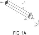
- FIG. 1A is a perspective view schematically illustrating the antenna device according to the embodiment.
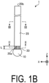
- FIG. 1B is a side view schematically illustrating the antenna device according to the embodiment.
- FIG. 1B is a view of one side of a support as viewed in plan view in a perpendicular direction of the one side.
- an antenna device 1 includes an antenna portion 10, a support 20, and connecting portions 30.
- FIGs. 1A and 1B illustrate a three-dimensional orthogonal coordinate system including a Z axis in which a vertically upward direction is a positive direction. Such an orthogonal coordinate system may also be presented in other drawings used in the description below. In the following description, the Z axis positive direction side may be referred to as "above" for convenience.
- the same and/or similar components as those of the antenna device 1 illustrated in FIGs. 1A and 1B are denoted by the same reference numerals, and descriptions thereof will be omitted or simplified.
- the antenna portion 10 includes, for example, an antenna element mounted on a wiring board.
- the antenna element includes, for example, an insulation substrate, a patch, and a circuitry.
- the insulation substrate includes, for example, a dielectric material or other insulation materials.
- the patch is, for example, an electrical conductor film made of an electrical conductive material such as copper.
- the circuitry includes, for example, an integrated circuit such as a Radio Frequency Integrated Circuit (RFIC).
- RFIC Radio Frequency Integrated Circuit
- the antenna portion 10 may further include, for example, a support member that supports an antenna element and a heat dissipation member.
- the heat dissipation member includes, for example, Thermal Interface Material (TIM), and dissipates heat generated by the antenna element.
- TIM Thermal Interface Material
- Such an antenna portion 10 is housed in a housing having a substantially spherical shape.
- the antenna portion 10 has an outer appearance having a substantially spherical shape as illustrated in FIGs. 1A and 1B .
- the support 20 is located above the antenna portion 10.
- the support 20 supports the antenna portion 10 via the connecting portions 30.
- the support 20 has a quadrangular prism shape elongated in the Z axis direction.
- the support 20 is fixed such that a first end 20a side closer to the antenna portion 10 is the lower side and a second end 20b side away from the antenna portion 10 is the upper side.
- the connecting portions 30 are located between the antenna portion 10 and the support 20, and connect the antenna portion 10 and the support 20.
- FIG. 2 is a cross-sectional view taken along II-II in FIG. 1B .
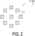
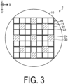
- FIG. 3 is a cross-sectional view taken along III-III in FIG. 1B . Note that in FIG. 3 , to facilitate understanding of a relationship between an outer shape of the support 20 and an outer shape of the antenna portion 10, a circle having a shape corresponding to the outer shape of the antenna portion 10 is given.
- the support 20 includes a plurality of channels 22.
- Each of the plurality of channels 22 is a through hole that penetrates the inside of the support 20 from the first end 20a to the second end 20b.
- the plurality of channels 22 are located side by side in the X axis direction and the Y axis direction, and a partition 23 defining adjacent ones of the plurality of channels 22 is located between the adjacent ones of the plurality of channels 22.
- the support 20 is located above the antenna portion 10.
- the support 20 includes the channels 22 extending from an inflow opening located opposite to the antenna portion 10 to an outflow opening located farther from the antenna portion 10 than the inflow opening.
- the inflow opening is located at the first end 20a.
- the outflow opening is located at the second end 20b.
- the support 20 includes heat dissipation portions 24.
- the heat dissipation portions 24 extend from the first end 20a to the second end 20b of the support 20 in parallel with the plurality of channels 22. In other words, the heat dissipation portions 24 are disposed to extend along the channels 22.
- Each of the heat dissipation portions 24 includes, for example, the plurality of channels 22 arranged in a lattice shape.
- the heat dissipation portions 24 extend in a height direction (Z axis direction) of the support 20 in a manner that some of the channels 22 among the plurality of channels 22 are blocked, and each of the plurality of channels 22 adjacent to the heat dissipation portion 24 is located in a manner that the periphery of the heat dissipation portion 24 is surrounded.
- the heat dissipation portions 24 may be located on the outer edge of the support 20, and may serve as a part of a peripheral wall 21 of the support 20.
- the support 20 supports the antenna portion 10 via the connecting portions 30, and has a heat dissipation function that contributes to the heat dissipation of the antenna portion 10.
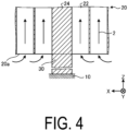
- connecting portions 30 As illustrated in FIG. 2 , in a cross-sectional view of the connecting portions 30, for example, members constituting the connecting portions 30 are present in an isolated state. That is, the connecting portions 30 are partially connected to both members of the antenna portion 10 and the support 20. This point will be described with reference to FIG. 4 .
- FIG. 4 is a cross-sectional view for explaining heat dissipation by the support.
- FIG. 4 only one connecting portion 30 is illustrated, but other connecting portions 30 also have the same and/or similar configuration.
- the temperature in the channels 22 located around the heat dissipation portion 24 rises.
- the air in the channels 22 moves from the lower side to the upper side in the height direction (Z axis direction) of the support 20 in the channels 22 as indicated by arrows 2, and the outside air is continuously taken in from the first end 20a of the channels 22 located at the lower end of the support 20.
- the antenna device 1 According to the antenna device 1 according to the embodiment, such a chimney effect is generated, and thus the radiation characteristics of the antenna portion 10 can be enhanced.
- the peripheral wall 21 (member located on the outermost side) constituting the support 20 may include a part where the thickness changes in the longitudinal direction of the support 20.
- a thinner part and a thicker part of the peripheral wall 21 may be alternately formed in the longitudinal direction of the support 20.
- the peripheral wall 21 constituting the support 20 may be thinner than the partition 23 of the inside.
- the peripheral wall 21 constituting the support 20 may include many thinner parts than the partition 23 of the inside.
- the support 20 may be, for example, a member made of a metal such as an aluminum alloy or the like.
- the support 20 may be integrally formed by, for example, extrusion molding or other methods, or may be formed by appropriately processing the support 20 that is individually formed for each portion.
- Each of the connecting portions 30 is a solid rod shape body located between a respective one of the heat dissipation portions 24 of the support 20 and the antenna portion 10. That is, the connecting portions 30 partially connect the antenna portion 10 and the support 20. In this case, each of the connecting portions 30 may be connected to the heat dissipation portions 24 in the support 20.
- An area of a horizontal cross-section of the connecting portions 30 is smaller than an area of a horizontal cross-section of the support 20.
- the outside air easily enters the channel 22 from the first end 20a side of the support 20, and the radiation characteristics is further enhanced.
- An increase in the total weight of the antenna device 1 due to the connecting portions 30 can be suppressed.
- the horizontal cross-section of the connecting portions 30 is a plane indicated by the line II-II in FIG. 1B .
- the connecting portions 30 may be, for example, members made of a metal such as an aluminum alloy or the like.
- the connecting portions 30 may be integrally formed with the support 20 by, for example, extrusion molding or other methods, or may be formed by bonding an individually formed rod shape bodies to the support 20 and/or the antenna portion 10 by welding, adhesion, or the like.
- a length L (see FIG. 1B ) of the connecting portions 30 that define a distance between the antenna portion 10 and the support 20 can be, for example, from 1 cm to 10 cm, particularly from 1 cm to 5 cm, further from 1.5 cm to 3 cm. By defining the length L in this manner, the radiation characteristics of the antenna device 1 can be enhanced.
- the length L is not limited to the range described above, and can be appropriately set according to, for example, the number, positions, and sizes of the connecting portions 30.
- an outer shape of the support 20 as viewed in the Z axis direction is located to be inscribed in an outer shape of the antenna portion 10.
- the outer shape of the support 20 may be larger than or smaller than the outer shape of the antenna portion 10.
- the outer shape of the support 20 is rectangular, and the outer shape of the antenna portion 10 is circular, and for example, the outer shape of the antenna portion 10 is small enough to fit into the outer shape of the support 20, the outside air easily flows into the channels 22 of the support 20 from the antenna portion 10 side in the Z axis.
- the radiation characteristics of the antenna portion 10 is further enhanced.
- FIG. 5 is a cross-sectional view schematically illustrating the antenna device according to a first variation of the embodiment.
- FIG. 5 illustrates a cross-section at the same position as in FIG. 3 .
- the circle having the shape corresponding to the outer shape of the antenna portion 10 is given.
- the antenna device 1 illustrated in FIG. 5 differs from the antenna device 1 according to the embodiment in that the antenna device 1 includes heat dissipation portions 40 instead of the heat dissipation portions 24 of the support 20.
- the heat dissipation portions 40 have a higher coefficient of thermal conductivity than other portions such as the peripheral wall 21 and the partition 23 of the support 20.
- the radiation characteristics of the antenna portion 10 can be further enhanced.
- a material of the heat dissipation portions 40 for example, a metal material such as copper having a higher coefficient of thermal conductivity than the material of the support 20 can be used.
- a material of the connecting portions 30 may be the same as the material of the heat dissipation portions 40. By making the connecting portions 30 from the same material as the material of the heat dissipation portions 40, the radiation characteristics are further enhanced.
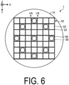
- FIG. 6 is a cross-sectional view schematically illustrating the antenna device according to a second variation of the embodiment.
- FIG. 6 illustrates a cross-section at the same position as in FIG. 3 .
- a circle having a shape corresponding to the outer shape of the antenna portion 10 is given.
- the antenna device 1 illustrated in FIG. 6 differs from the antenna device 1 according to the first variation in that the antenna device 1 includes heat pipes 50 instead of the heat dissipation portions 40.
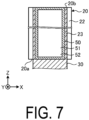
- FIG. 7 is a cross-sectional view taken along VII-VII in FIG. 6 .
- the heat pipe 50 includes a hollow portion 51 at an inner portion thereof.
- the hollow portion 51 is sealed with a cooling medium 52.
- the cooling medium 52 is vaporized when the heat pipe 50 is heated, and is condensed when the heat pipe 50 is cooled.
- a material of the heat pipe 50 may be, for example, copper.
- the cooling medium 52 may be, for example, water or a substitute for CFCs (e.g., HFC-134a).
- the heat pipe 50 illustrated in FIG. 7 is located from the first end 20a to the second end 20b of the support 20, and is not located in the connecting portion 30.
- the heat pipe 50 may be located, for example, from an inner portion of the connecting portion 30 to the second end 20b of the support 20.
- the heat pipe 50 need not be located, for example, up to the second end 20b of the support 20.
- the heat dissipation portion 24 or the heat dissipation portion 40 may be located up to the second end 20b of the support 20.
- the heat pipe 50 is disposed along the channel 22 at an inner portion of at least one of the support 20 or the heat dissipation portion 24.
- the antenna device 1 according to the above-described embodiment and each of the variations is described as including any one of the heat dissipation portions 24 and 40 and the heat pipes 50, but may include two or more types of heat dissipation mechanisms, such as, for example, the heat dissipation portions 24 and heat pipes 50.
- the connecting portions 30 are described as the solid rod shape bodies, but may be, for example, hollow tubular bodies. Making the inner portion of each of the connecting portions 30 hollow makes it possible to contribute to weight reduction of the antenna device 1. As the same as and/or similar to the heat pipes 50 described above, the hollow may be sealed with the cooling medium 52, and thus the radiation characteristics in the connecting portions 30 can be further enhanced.
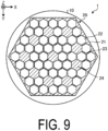
- FIGs. 8 and 9 are cross-sectional views each schematically illustrating the antenna device according to a third and a fourth variations of the embodiment.
- FIG. 8 and FIG. 9 also illustrate cross-sections at the same position as in FIG. 3 .
- the circle having a shape corresponding to the outer shape of the antenna portion 10 is given.
- the antenna device 1 according to the third variation differs from each antenna device 1 described above in that the shape of the cross-section (outer shape) of the support 20 is circular.
- the support 20 constituting the antenna device 1 according to the third variation has an outer appearance having a cylindrical shape.
- the antenna device 1 according to the fourth variation illustrated in FIG. 9 differs from each antenna device 1 described above in that the shape of the cross-section (outer shape) of the support 20 is a hexagon.
- the support 20 constituting the antenna device 1 according to the fourth variation has an outer appearance having a hexagonal prism shape. In this way, the support 20 may have a pillar shape elongated in the Z axis direction, and the shape of the support 20 is not particularly limited.
- the antenna device 1 illustrated in FIG. 8 includes the plurality of channels 22 that are through holes each having a cylindrical shape.
- the antenna device 1 illustrated in FIG. 9 includes the plurality of channels 22 that are through holes each having a cross-section of a hexagonal shape.
- the channels 22 formed in the support 20 may include the plurality of channels 22 extending in the Z axis direction.
- a shape of each of the channels 22 and a shape of each of the heat dissipation portions 24 associated with an array of the channels 22 are not particularly limited.
- the shapes may be deformed by a shape of the wall surface of the construction in which the support 20 is installed. When the wall surface of the construction is, for example, curved, the support 20 may also be deformed to conform the wall surface of the construction.
- the support 20 When the support 20 has a shape to conform the wall surface of a building, a portion of the support 20 protruding from the wall surface is reduced, and thus, a probability that the support 20 is damaged or deformed due to collision of an object or the like is reduced. Harmony with an outer appearance of the building is maintained.
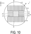
- FIG. 10 is a cross-sectional view schematically illustrating the antenna device according to a fifth variation of the embodiment.
- FIG. 10 also illustrates a cross-section at the same position as in FIG. 3 .
- a circle having a shape corresponding to the outer shape of the antenna portion 10 is given.
- the support 20 constituting the antenna device 1 illustrated in FIG. 10 includes a heat dissipation portion 24, a plurality of first fin members 25, and a plurality of second fin members 26.
- the heat dissipation portion 24 is located at a center of the support 20.
- a shape of the cross-section of the heat dissipation portion 24 is rectangular (square in the case of FIG. 10 ).
- the plurality of first fin members 25 and the plurality of second fin members 26 are fixed to side surfaces of the heat dissipation portion 24 at approximately equal intervals.
- the plurality of first fin members 25 are disposed on the side surface of the heat dissipation portion 24 in the Y direction.
- the plurality of second fin members 26 are disposed on the side surface of the heat dissipation portion 24 in the X direction.
- the plurality of first fin members 25 are fixed to the side surface of the heat dissipation portion 24 perpendicular to the X direction.
- the plurality of second fin members 26 are fixed to the side surface of the heat dissipation portion 24 perpendicular to the Y direction.
- each of the plurality of the first fin members 25 opposite to the heat dissipation portion 24 is oriented away from the side surface of the heat dissipation portion 24.
- An end portion of each of the plurality of the second fin members 26 opposite to the heat dissipation portion 24 is oriented away from the side surface of the heat dissipation portion 24.
- a length of each of the plurality of first fin members 25 from the side surface of the heat dissipation portion 24 to the end portion is the same, but the length may be changed along with the outer shape of the antenna portion 10. For example, a space between two first fin members 25 is the channel 22. A space between two second fin members 26 is the channel 22. That is, the antenna device 1 illustrated in FIG.
- the 10 includes the support 20 including the plurality of first fin members 25 whose adjacent ones sandwich the channel 22 and the plurality of second fin members 26 whose adjacent ones sandwich the channel 22.
- the plurality of first fin members 25 are located at intervals in the Y axis direction.
- Each of the first fin members 25 extends along a ZX plane from the heat dissipation portion 24, and the channel 22 is located between adjacent ones of the first fin members 25.
- the plurality of second fin members 26 are located at intervals in the X axis direction.
- Each of the second fin members 26 extends along a YZ plane from the heat dissipation portion 24 and the first fin members 25, and the channel 22 is located between adjacent ones of the second fin members 26.
- the antenna device 1 according to the present variation differs from each antenna device 1 according to the embodiment and the variations described above in that a plurality of the channels 22 are located outside the support 20. In this way, even when the plurality of channels 22 are located outside the support 20, the antenna device 1 can be properly dissipated.
- FIG. 11 is a diagram for comparing radiation characteristics of antenna devices.
- experimental examples 1 to 3 the influence of differences in shape of the support 20 on the heat dissipation performance was evaluated.
- experimental examples 1 and 4 to 9 the influence of differences in the length L of the connecting portions 30 illustrated in FIG. 1B on the heat dissipation performance was evaluated.
- experimental examples 5 and 10 differences of the heat dissipation performance due to the presence of the heat pipes 50 (see FIGs. 6 and 7 ) were compared.
- the support 20 having a quadrangular prism shape, in which lengths in the X axis direction, the Y axis direction, and the Z axis direction are 105 mm, 105 mm, and 1000 mm, respectively, was used.
- An aluminum alloy having a coefficient of thermal conductivity 222 W/(m•K) was used as a material of the support 20 and the connecting portions 30.
- the antenna device 1 having the same dimensions as in the experimental example 1 was prepared except that the length L of the connecting portions 30 was changed.
- the support 20 having a cylindrical shape in which the first end 20a and the second end 20b along the XY plane were circular with a diameter of 120 mm and a length in the Z axis direction was 1000 mm.
- the support 20 having a hexagonal prism shape was used.
- the first end 20a and the second end 20b along the XY plane were equilateral hexagons having substantially the same cross-sectional area as that of the support 20 according to the experimental example 2, and the length in the Z axis direction was 1000 mm.
- maximum temperature refers to a temperature at a site where a surface temperature is highest in the antenna element housed in the antenna portion 10.
- the maximum temperature of the antenna portion 10 was reduced as compared with the antenna device 1 according to the experimental examples 2 and 3. It is conceivable that this is because the areas of the first end 20a and the second end 20b are different, and the surface area of the partition wall 23 in contact with the channel 22 is different. Note that it was confirmed that the antenna device 1 according to the experimental examples 2 and 3 also had the radiation characteristics suitable for actual use.
- the experimental example 10 to which the heat pipes 50 were applied further reduced the maximum temperature of the antenna portion 10 as compared with the experimental example 5. It was confirmed that the antenna device 1 to which the heat pipes 50 were applied had higher radiation characteristics as compared with the antenna device 1 to which the heat pipes 50 were not applied.
Landscapes
- Support Of Aerials (AREA)
- Cooling Or The Like Of Electrical Apparatus (AREA)
- Non-Reversible Transmitting Devices (AREA)
Claims (9)
- Antennenvorrichtung (1), aufweisend:einen Antennenabschnitt (10),einen Verbindungsabschnitt (30) undeinen Träger (20), wobeider Verbindungsabschnitt (30) den Antennenabschnitt (10) und den Träger (20) verbindet,dadurch gekennzeichnet, dass der Träger (20) über dem Antennenabschnitt (10) angeordnet ist und einen Kanal (22) aufweist, der sich von einer Einströmöffnung, die gegenüber dem Antennenabschnitt (10) angeordnet ist, zu einer Ausströmöffnung erstreckt, die weiter von dem Antennenabschnitt (10) entfernt als die Einströmöffnung angeordnet ist.
- Antennenvorrichtung (1) gemäß Anspruch 1, wobei
der Kanal (22) ein Durchgangsloch aufweist, das durch den Träger (20) in einer Höhenrichtung hindurchtritt. - Antennenvorrichtung (1) gemäß Anspruch 1 oder 2, wobei
der Träger (20) einen Wärmeabfuhrabschnitt (24, 40) aufweist, der sich entlang des Kanals (22) erstreckt. - Antennenvorrichtung (1) gemäß Anspruch 3, wobei
der Wärmeabfuhrabschnitt (24, 40) einen höheren Wärmeleitfähigkeitskoeffizienten als ein Wärmeleitfähigkeitskoeffizient eines anderen Teils des Trägers (20) mit Ausnahme des Wärmeabfuhrabschnitts (24) aufweist. - Antennenvorrichtung (1) gemäß Anspruch 3 oder 4, wobei
der Träger (20) und/oder der Wärmeabfuhrabschnitt (24, 40) ein Wärmerohr (50) entlang des Kanals (22) an einem inneren Abschnitt des Trägers (20) und/oder des Wärmeabfuhrabschnitts (24, 40) aufweist. - Antennenvorrichtung (1) gemäß irgendeinem der Ansprüche 3 bis 5, wobei
der Verbindungsabschnitt (30) mit dem Wärmeabfuhrabschnitt (24, 40) in dem Träger (20) verbunden ist. - Antennenvorrichtung (1) gemäß Anspruch 6, wobei
eine Fläche eines horizontalen Querschnitts des Verbindungsabschnitts (30) kleiner als eine Fläche eines horizontalen Querschnitts des Trägers (20) ist. - Antennenvorrichtung (1) gemäß irgendeinem der Ansprüche 1 bis 7, wobei
der Verbindungsabschnitt (30) eine Mehrzahl stabförmiger Körper ist, die sich in der gleichen Richtung wie der Kanal (22) erstrecken. - Antennenvorrichtung (1) gemäß Anspruch 8, wobei
jeder aus der Mehrzahl stabförmiger Körper ein hohler röhrenförmiger Körper ist.
Applications Claiming Priority (2)
| Application Number | Priority Date | Filing Date | Title |
|---|---|---|---|
| JP2020181911 | 2020-10-29 | ||
| PCT/JP2021/039864 WO2022092220A1 (ja) | 2020-10-29 | 2021-10-28 | アンテナ装置 |
Publications (3)
| Publication Number | Publication Date |
|---|---|
| EP4239788A1 EP4239788A1 (de) | 2023-09-06 |
| EP4239788A4 EP4239788A4 (de) | 2024-10-09 |
| EP4239788B1 true EP4239788B1 (de) | 2025-04-09 |
Family
ID=81383360
Family Applications (1)
| Application Number | Title | Priority Date | Filing Date |
|---|---|---|---|
| EP21886337.1A Active EP4239788B1 (de) | 2020-10-29 | 2021-10-28 | Antennenvorrichtung |
Country Status (5)
| Country | Link |
|---|---|
| US (1) | US12294134B2 (de) |
| EP (1) | EP4239788B1 (de) |
| JP (1) | JP7504218B2 (de) |
| CN (1) | CN116349417A (de) |
| WO (1) | WO2022092220A1 (de) |
Families Citing this family (1)
| Publication number | Priority date | Publication date | Assignee | Title |
|---|---|---|---|---|
| WO2022145205A1 (ja) * | 2020-12-28 | 2022-07-07 | 京セラ株式会社 | アンテナ装置 |
Family Cites Families (12)
| Publication number | Priority date | Publication date | Assignee | Title |
|---|---|---|---|---|
| JPS60114701A (ja) * | 1983-11-28 | 1985-06-21 | Nippon Steel Corp | 容器内壁測距装置 |
| JPH04131054U (ja) * | 1991-05-27 | 1992-12-01 | 日本電信電話株式会社 | 送受信機 |
| JP3518876B2 (ja) * | 1992-09-29 | 2004-04-12 | オリンパス株式会社 | 温熱治療装置 |
| JP3205663B2 (ja) | 1994-06-29 | 2001-09-04 | 日本電子株式会社 | 荷電粒子ビーム装置 |
| JPH08316672A (ja) * | 1995-05-22 | 1996-11-29 | Kikukawa Kogyo Kk | 筒状構造物の内部放熱構造 |
| CN101217858B (zh) * | 2008-01-09 | 2010-06-23 | 华为技术有限公司 | 通信设备的散热方法和系统 |
| DE202009001821U1 (de) * | 2009-02-12 | 2009-04-16 | Kathrein-Werke Kg | Antenne, insbesondere Mobilfunkantenne |
| JP5913765B2 (ja) | 2012-02-05 | 2016-04-27 | 株式会社関電工 | 電柱装着用架台及びこの電柱装着用架台を用いた吊荷の電柱装着工法 |
| WO2014065721A1 (en) * | 2012-10-22 | 2014-05-01 | Telefonaktiebolaget L M Ericsson (Publ) | Mast arrangement radio network node and related method |
| JP3205663U (ja) | 2016-05-27 | 2016-08-04 | 町田市 | Wi−Fi街路灯 |
| JP2018048461A (ja) | 2016-09-21 | 2018-03-29 | 住友商事株式会社 | 多機能構造体 |
| US12003016B2 (en) * | 2018-10-29 | 2024-06-04 | Commscope Technologies Llc | Perforated door for monopole module and method of mounting same |
-
2021
- 2021-10-28 CN CN202180070234.1A patent/CN116349417A/zh active Pending
- 2021-10-28 EP EP21886337.1A patent/EP4239788B1/de active Active
- 2021-10-28 WO PCT/JP2021/039864 patent/WO2022092220A1/ja not_active Ceased
- 2021-10-28 JP JP2022559235A patent/JP7504218B2/ja active Active
- 2021-10-28 US US18/031,842 patent/US12294134B2/en active Active
Also Published As
| Publication number | Publication date |
|---|---|
| EP4239788A4 (de) | 2024-10-09 |
| CN116349417A (zh) | 2023-06-27 |
| US12294134B2 (en) | 2025-05-06 |
| JPWO2022092220A1 (de) | 2022-05-05 |
| WO2022092220A1 (ja) | 2022-05-05 |
| US20230387565A1 (en) | 2023-11-30 |
| JP7504218B2 (ja) | 2024-06-21 |
| EP4239788A1 (de) | 2023-09-06 |
Similar Documents
| Publication | Publication Date | Title |
|---|---|---|
| US7092255B2 (en) | Thermal management system and method for electronic equipment mounted on coldplates | |
| US9496589B2 (en) | System for packaging and thermal management of battery cells | |
| US8797226B2 (en) | Antenna heat fins | |
| US20190221939A1 (en) | Dielectric resonator antenna having first and second dielectric portions | |
| US20200021005A1 (en) | Heat-dissipation mechanism and wireless communication device | |
| US10476150B2 (en) | Wireless communication device | |
| US20050094375A1 (en) | Integrated heat dissipating device with curved fins | |
| US20100266886A1 (en) | Round cell battery | |
| EP4239788B1 (de) | Antennenvorrichtung | |
| CN115380637A (zh) | 具有改进的热负荷管理的电信壳体 | |
| JP2009540708A (ja) | 平面多層アンテナ | |
| CN1736000A (zh) | 低价位天线阵列 | |
| KR101648831B1 (ko) | 경량화한 중계기 함체 | |
| CA2223974C (en) | Antenna having double-sided printed circuit board with colinear, alternating and opposing radiating elements and microstrip transmission lines | |
| JP2005303063A (ja) | ヒートシンク | |
| JP6837932B2 (ja) | アンテナ | |
| CN101087505A (zh) | 散热装置 | |
| US11268772B2 (en) | Heat transfer device | |
| US11476556B1 (en) | Remote active cooling heat exchanger and antenna system with the same | |
| JP7164019B2 (ja) | 冷却構造体 | |
| JP2008311253A (ja) | フィルムコンデンサ及びフィルムコンデンサユニット | |
| CN112201921B (zh) | 一种路灯天线 | |
| CN221151704U (zh) | 一种汽车域控制器 | |
| CN222546071U (zh) | 一种易散热ac电感盒 | |
| JP2000283670A (ja) | ヒートシンク |
Legal Events
| Date | Code | Title | Description |
|---|---|---|---|
| STAA | Information on the status of an ep patent application or granted ep patent |
Free format text: STATUS: THE INTERNATIONAL PUBLICATION HAS BEEN MADE |
|
| PUAI | Public reference made under article 153(3) epc to a published international application that has entered the european phase |
Free format text: ORIGINAL CODE: 0009012 |
|
| STAA | Information on the status of an ep patent application or granted ep patent |
Free format text: STATUS: REQUEST FOR EXAMINATION WAS MADE |
|
| 17P | Request for examination filed |
Effective date: 20230418 |
|
| AK | Designated contracting states |
Kind code of ref document: A1 Designated state(s): AL AT BE BG CH CY CZ DE DK EE ES FI FR GB GR HR HU IE IS IT LI LT LU LV MC MK MT NL NO PL PT RO RS SE SI SK SM TR |
|
| DAV | Request for validation of the european patent (deleted) | ||
| DAX | Request for extension of the european patent (deleted) | ||
| REG | Reference to a national code |
Ref legal event code: R079 Ipc: H01Q0001020000 Ref country code: DE Ref legal event code: R079 Ref document number: 602021029063 Country of ref document: DE Free format text: PREVIOUS MAIN CLASS: H01Q0001120000 Ipc: H01Q0001020000 |
|
| A4 | Supplementary search report drawn up and despatched |
Effective date: 20240910 |
|
| RIC1 | Information provided on ipc code assigned before grant |
Ipc: H01Q 1/12 20060101ALI20240904BHEP Ipc: H01Q 1/02 20060101AFI20240904BHEP |
|
| RIC1 | Information provided on ipc code assigned before grant |
Ipc: H01Q 1/12 20060101ALI20241112BHEP Ipc: H01Q 1/02 20060101AFI20241112BHEP |
|
| GRAP | Despatch of communication of intention to grant a patent |
Free format text: ORIGINAL CODE: EPIDOSNIGR1 |
|
| STAA | Information on the status of an ep patent application or granted ep patent |
Free format text: STATUS: GRANT OF PATENT IS INTENDED |
|
| INTG | Intention to grant announced |
Effective date: 20250107 |
|
| GRAS | Grant fee paid |
Free format text: ORIGINAL CODE: EPIDOSNIGR3 |
|
| GRAA | (expected) grant |
Free format text: ORIGINAL CODE: 0009210 |
|
| STAA | Information on the status of an ep patent application or granted ep patent |
Free format text: STATUS: THE PATENT HAS BEEN GRANTED |
|
| AK | Designated contracting states |
Kind code of ref document: B1 Designated state(s): AL AT BE BG CH CY CZ DE DK EE ES FI FR GB GR HR HU IE IS IT LI LT LU LV MC MK MT NL NO PL PT RO RS SE SI SK SM TR |
|
| REG | Reference to a national code |
Ref country code: GB Ref legal event code: FG4D |
|
| REG | Reference to a national code |
Ref country code: CH Ref legal event code: EP |
|
| REG | Reference to a national code |
Ref country code: DE Ref legal event code: R096 Ref document number: 602021029063 Country of ref document: DE |
|
| REG | Reference to a national code |
Ref country code: IE Ref legal event code: FG4D |
|
| REG | Reference to a national code |
Ref country code: NL Ref legal event code: MP Effective date: 20250409 |
|
| PG25 | Lapsed in a contracting state [announced via postgrant information from national office to epo] |
Ref country code: NL Free format text: LAPSE BECAUSE OF FAILURE TO SUBMIT A TRANSLATION OF THE DESCRIPTION OR TO PAY THE FEE WITHIN THE PRESCRIBED TIME-LIMIT Effective date: 20250409 |
|
| REG | Reference to a national code |
Ref country code: AT Ref legal event code: MK05 Ref document number: 1784422 Country of ref document: AT Kind code of ref document: T Effective date: 20250409 |
|
| PG25 | Lapsed in a contracting state [announced via postgrant information from national office to epo] |
Ref country code: FI Free format text: LAPSE BECAUSE OF FAILURE TO SUBMIT A TRANSLATION OF THE DESCRIPTION OR TO PAY THE FEE WITHIN THE PRESCRIBED TIME-LIMIT Effective date: 20250409 Ref country code: ES Free format text: LAPSE BECAUSE OF FAILURE TO SUBMIT A TRANSLATION OF THE DESCRIPTION OR TO PAY THE FEE WITHIN THE PRESCRIBED TIME-LIMIT Effective date: 20250409 Ref country code: PT Free format text: LAPSE BECAUSE OF FAILURE TO SUBMIT A TRANSLATION OF THE DESCRIPTION OR TO PAY THE FEE WITHIN THE PRESCRIBED TIME-LIMIT Effective date: 20250811 |
|
| REG | Reference to a national code |
Ref country code: LT Ref legal event code: MG9D |
|
| PG25 | Lapsed in a contracting state [announced via postgrant information from national office to epo] |
Ref country code: GR Free format text: LAPSE BECAUSE OF FAILURE TO SUBMIT A TRANSLATION OF THE DESCRIPTION OR TO PAY THE FEE WITHIN THE PRESCRIBED TIME-LIMIT Effective date: 20250710 Ref country code: NO Free format text: LAPSE BECAUSE OF FAILURE TO SUBMIT A TRANSLATION OF THE DESCRIPTION OR TO PAY THE FEE WITHIN THE PRESCRIBED TIME-LIMIT Effective date: 20250709 |
|
| PG25 | Lapsed in a contracting state [announced via postgrant information from national office to epo] |
Ref country code: PL Free format text: LAPSE BECAUSE OF FAILURE TO SUBMIT A TRANSLATION OF THE DESCRIPTION OR TO PAY THE FEE WITHIN THE PRESCRIBED TIME-LIMIT Effective date: 20250409 |
|
| PGFP | Annual fee paid to national office [announced via postgrant information from national office to epo] |
Ref country code: IT Payment date: 20250922 Year of fee payment: 5 |
|
| PG25 | Lapsed in a contracting state [announced via postgrant information from national office to epo] |
Ref country code: BG Free format text: LAPSE BECAUSE OF FAILURE TO SUBMIT A TRANSLATION OF THE DESCRIPTION OR TO PAY THE FEE WITHIN THE PRESCRIBED TIME-LIMIT Effective date: 20250409 |
|
| PGFP | Annual fee paid to national office [announced via postgrant information from national office to epo] |
Ref country code: GB Payment date: 20250904 Year of fee payment: 5 |
|
| PG25 | Lapsed in a contracting state [announced via postgrant information from national office to epo] |
Ref country code: HR Free format text: LAPSE BECAUSE OF FAILURE TO SUBMIT A TRANSLATION OF THE DESCRIPTION OR TO PAY THE FEE WITHIN THE PRESCRIBED TIME-LIMIT Effective date: 20250409 |
|
| PG25 | Lapsed in a contracting state [announced via postgrant information from national office to epo] |
Ref country code: AT Free format text: LAPSE BECAUSE OF FAILURE TO SUBMIT A TRANSLATION OF THE DESCRIPTION OR TO PAY THE FEE WITHIN THE PRESCRIBED TIME-LIMIT Effective date: 20250409 |
|
| PGFP | Annual fee paid to national office [announced via postgrant information from national office to epo] |
Ref country code: FR Payment date: 20250908 Year of fee payment: 5 |
|
| PG25 | Lapsed in a contracting state [announced via postgrant information from national office to epo] |
Ref country code: RS Free format text: LAPSE BECAUSE OF FAILURE TO SUBMIT A TRANSLATION OF THE DESCRIPTION OR TO PAY THE FEE WITHIN THE PRESCRIBED TIME-LIMIT Effective date: 20250709 |
|
| PG25 | Lapsed in a contracting state [announced via postgrant information from national office to epo] |
Ref country code: IS Free format text: LAPSE BECAUSE OF FAILURE TO SUBMIT A TRANSLATION OF THE DESCRIPTION OR TO PAY THE FEE WITHIN THE PRESCRIBED TIME-LIMIT Effective date: 20250809 |
|
| PG25 | Lapsed in a contracting state [announced via postgrant information from national office to epo] |
Ref country code: LV Free format text: LAPSE BECAUSE OF FAILURE TO SUBMIT A TRANSLATION OF THE DESCRIPTION OR TO PAY THE FEE WITHIN THE PRESCRIBED TIME-LIMIT Effective date: 20250409 |
|
| PGFP | Annual fee paid to national office [announced via postgrant information from national office to epo] |
Ref country code: DE Payment date: 20250902 Year of fee payment: 5 |
|
| REG | Reference to a national code |
Ref country code: DE Ref legal event code: R097 Ref document number: 602021029063 Country of ref document: DE |
|
| PG25 | Lapsed in a contracting state [announced via postgrant information from national office to epo] |
Ref country code: DK Free format text: LAPSE BECAUSE OF FAILURE TO SUBMIT A TRANSLATION OF THE DESCRIPTION OR TO PAY THE FEE WITHIN THE PRESCRIBED TIME-LIMIT Effective date: 20250409 Ref country code: SM Free format text: LAPSE BECAUSE OF FAILURE TO SUBMIT A TRANSLATION OF THE DESCRIPTION OR TO PAY THE FEE WITHIN THE PRESCRIBED TIME-LIMIT Effective date: 20250409 |
|
| PG25 | Lapsed in a contracting state [announced via postgrant information from national office to epo] |
Ref country code: CZ Free format text: LAPSE BECAUSE OF FAILURE TO SUBMIT A TRANSLATION OF THE DESCRIPTION OR TO PAY THE FEE WITHIN THE PRESCRIBED TIME-LIMIT Effective date: 20250409 |
|
| PG25 | Lapsed in a contracting state [announced via postgrant information from national office to epo] |
Ref country code: EE Free format text: LAPSE BECAUSE OF FAILURE TO SUBMIT A TRANSLATION OF THE DESCRIPTION OR TO PAY THE FEE WITHIN THE PRESCRIBED TIME-LIMIT Effective date: 20250409 |
|
| PG25 | Lapsed in a contracting state [announced via postgrant information from national office to epo] |
Ref country code: SK Free format text: LAPSE BECAUSE OF FAILURE TO SUBMIT A TRANSLATION OF THE DESCRIPTION OR TO PAY THE FEE WITHIN THE PRESCRIBED TIME-LIMIT Effective date: 20250409 |
|
| PLBE | No opposition filed within time limit |
Free format text: ORIGINAL CODE: 0009261 |
|
| STAA | Information on the status of an ep patent application or granted ep patent |
Free format text: STATUS: NO OPPOSITION FILED WITHIN TIME LIMIT |
|
| REG | Reference to a national code |
Ref country code: CH Ref legal event code: L10 Free format text: ST27 STATUS EVENT CODE: U-0-0-L10-L00 (AS PROVIDED BY THE NATIONAL OFFICE) Effective date: 20260218 |
|
| PG25 | Lapsed in a contracting state [announced via postgrant information from national office to epo] |
Ref country code: RO Free format text: LAPSE BECAUSE OF FAILURE TO SUBMIT A TRANSLATION OF THE DESCRIPTION OR TO PAY THE FEE WITHIN THE PRESCRIBED TIME-LIMIT Effective date: 20250409 |
|
| 26N | No opposition filed |
Effective date: 20260112 |